
73083–01
–
THEFT DETERRENT & DOOR LOCK
POWER DOOR LOCK CONTROL SYSTEM
73–1
2634
Author:
Date:
2002 CAMRY REPAIR MANUAL (RM881U)
POWER DOOR LOCK CONTROL SYSTEM
ON–VEHICLE INSPECTION
1.
DOOR LOCK FAIL–SAFE
(a)
When a malfunction in the door control switch (manual switch, interlocked operation with key) has been
detected, door LOCK/UNLOCK operations become unable.
2.
CHECK FOR ELECTRICAL DOOR LOCK OPERATION
(a)
Check the basic function.
(1)
Check all doors will lock when the door control switch (for manual operation) is turned to the lock
side and all doors will unlock when turned to the unlock side.
(2)
Check all doors will lock when the driver’s door is operated to be lock and all doors will unlock
when operated to be unlock, by the key operation outside the vehicle.
(b)
Check the key confinement prevention function.
NOTICE:
In order to prevent the key from confined, the inspection should be made with the driver’s door glass
open.
(1)
Insert the ignition key into the ignition switch lock cylinder.
(2)
With the driver’s door open, check all doors will immediately unlock when the door lock knob for
the driver’s door is turned to the lock side.
(3)
With the driver’s door open, check all doors will immediately unlock when the door control switch
(for manual operation) is turned to the lock side.
(4)
With the driver’s door open, lock the driver’s door lock by holding the driver’s door lock knob in
the lock side for 2 seconds or more and then close the driver’s door. Then, check that all doors
will unlock.
(c)
Check the security function.
(1)
Close all doors with the driver’s door glass open so that the door control switch can be operated
outside the vehicle.
(2)
Pull out the ignition key, open the driver’s door, and close and lock the door without a key opera-
tion. Under this condition, check that all doors will not unlock when the door control switch (for
manual operation) is turned to the unlock side outside the vehicle.
(3)
Pull out the ignition key, close and lock the driver’s door by the key operation. Under this condi-
tion, check that all doors will not unlock when the door control switch (for manual operation) is
turned to the unlock side outside the vehicle.
(4)
Pull out the ignition key, close the driver’s door and lock the door by the wireless door lock opera-
tion. Under this condition, check that all doors will not unlock when the door control switch (for
manual operation) is turned to the unlock side outside the vehicle.
HINT:
Under the conditions below, check that the security function will cancel.
Ignition switch turned ON.
Driver’s door unlocked by the key operation.
Door control switch (for manual operation) turned to the unlock side after unlocking the door control
knob manually.
Doors are unlocked by the wireless operation.

73–2
–
THEFT DETERRENT & DOOR LOCK
POWER DOOR LOCK CONTROL SYSTEM
2635
Author:
Date:
2002 CAMRY REPAIR MANUAL (RM881U)
(d)
Check the illumination function.
(1)
Move the map light switch in the DOOR position.
(2)
Check that the map light will be on simultaneously with all doors’ unlocking operation when the
driver’s door of all the closing doors is turned unlock by the key operation.
(3)
Map light will be off in approximately 15 seconds if a door has not been opened for a while.
73082–01
B56102
Unlock
Lock
B56797
Unlock
Lock
–
THEFT DETERRENT & DOOR LOCK
POWER DOOR LOCK CONTROL SYSTEM
73–3
2636
Author:
Date:
2002 CAMRY REPAIR MANUAL (RM881U)
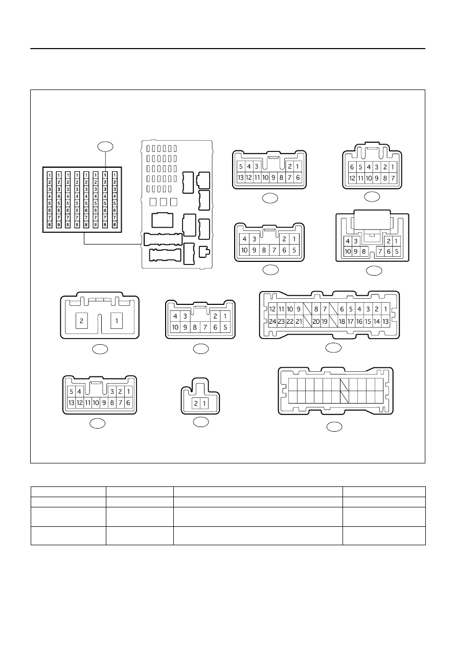
INSPECTION
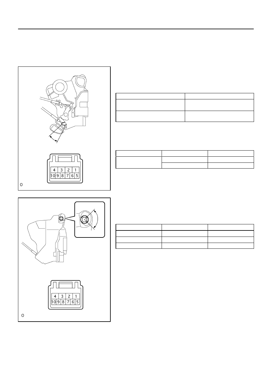
1.
INSPECT FRONT DOOR W/MOTOR LOCK ASSY RH
(a)
Inspect the door lock motor operation.
Standard:
Measuring condition
Operation
Battery positive – Terminal 4
Battery negative – Terminal 1
Lock
Battery positive – Terminal 1
Battery negative – Terminal 4
Unlock
If the operation is not as specified, replace the door lock assem-
bly.
(b)
Inspect the position switch continuity.
Standard:
Terminal No.
Door lock position
Specification
7
⇔
8
Lock
No continuity
7
⇔
8
Unlock
Continuity
If the continuity is not as specified, replace the door lock assem-
bly.
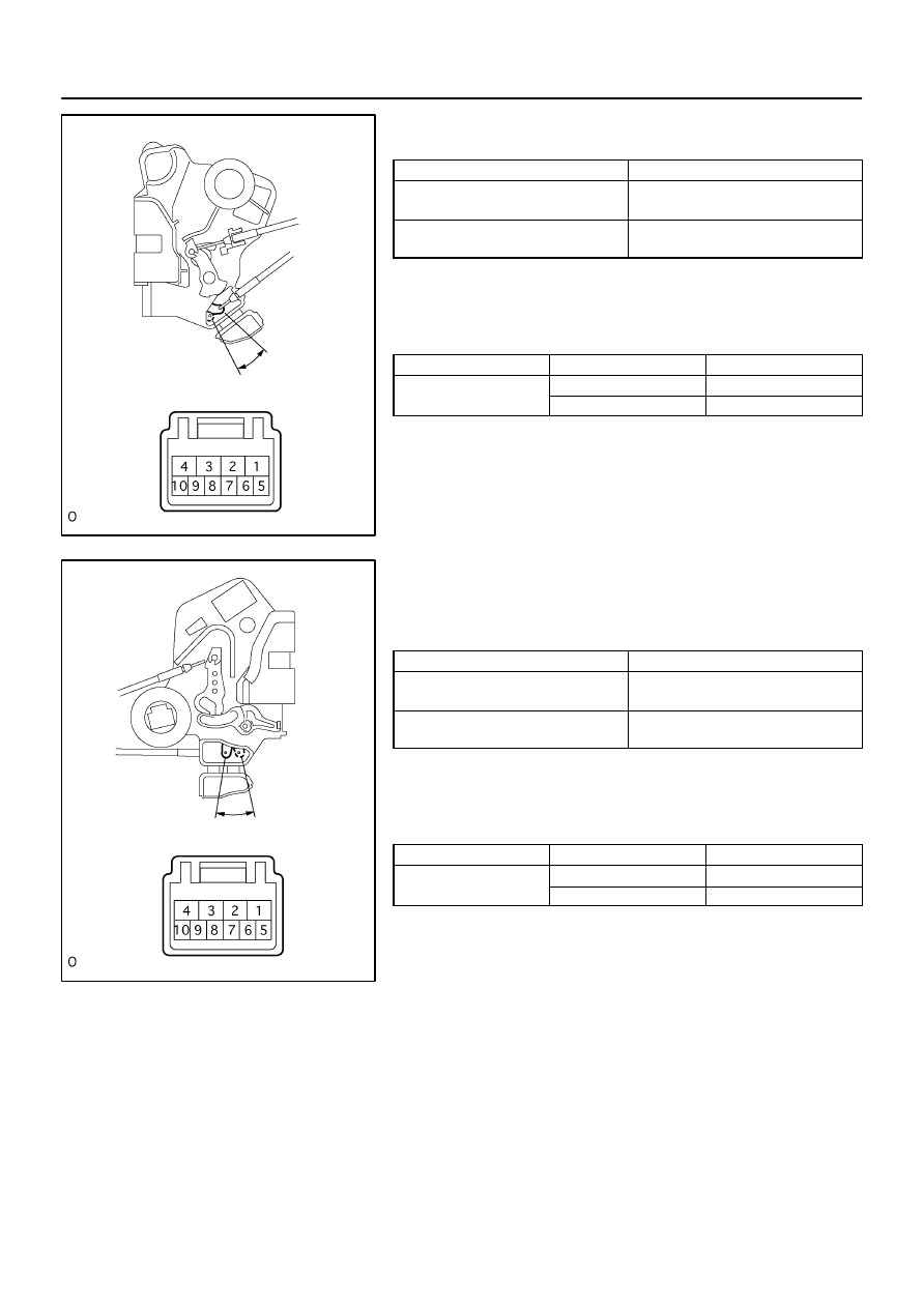
2.
INSPECT FRONT DOOR W/MOTOR LOCK ASSY LH
(a)
Inspect the door lock assembly continuity.
Standard:
Terminal No.
Switch position
Specified condition
9 – 7
Lock
Continuity
–
OFF
No continuity
10 – 7
Unlock
Continuity
If the operation is not as specified, replace the door lock assem-
bly.
B56798
Unlock
Lock
B56799
Unlock
Lock
73–4
–
THEFT DETERRENT & DOOR LOCK
POWER DOOR LOCK CONTROL SYSTEM
2637
Author:
Date:
2002 CAMRY REPAIR MANUAL (RM881U)
(b)
Inspect the door lock motor operation.
Standard:
Measuring condition
Operation
Battery positive – Terminal 4
Battery negative – Terminal 1
Lock
Battery positive – Terminal 1
Battery negative – Terminal 4
Unlock
If the operation is not as specified, replace the door lock assem-
bly.
(c)
Inspect the position switch continuity.
Standard:
Terminal No.
Door lock position
Specification
7
⇔
8
Lock
No continuity
7
⇔
8
Unlock
Continuity
If the continuity is not as specified, replace the door lock assem-
bly.
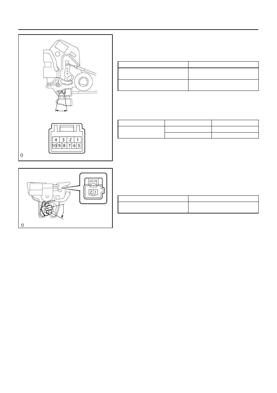
3.
INSPECT REAR DOOR W/MOTOR LOCK ASSY RH
(a)
Inspect the door lock motor operation.
Standard:
Measuring condition
Operation
Battery positive – Terminal 4
Battery negative – Terminal 1
Lock
Battery positive – Terminal 1
Battery negative – Terminal 4
Unlock
If the operation is not as specified, replace the door lock assem-
bly.
(b)
Inspect the position switch continuity.
Standard:
Terminal No.
Door lock position
Specification
6
⇔
9
Lock
No continuity
6
⇔
9
Unlock
Continuity
If the continuity is not as specified, replace the door lock assem-
bly.
B56800
Unlock
Lock
B56801
Open
–
THEFT DETERRENT & DOOR LOCK
POWER DOOR LOCK CONTROL SYSTEM
73–5
2638
Author:
Date:
2002 CAMRY REPAIR MANUAL (RM881U)
4.
INSPECT REAR DOOR W/MOTOR LOCK ASSY LH
(a)
Inspect the door lock motor operation.
Standard:
Measuring condition
Operation
Battery positive – Terminal 4
Battery negative – Terminal 1
Lock
Battery positive – Terminal 1
Battery negative – Terminal 4
Unlock
If the operation is not as specified, replace the door lock assem-
bly.
(b)
Inspect the position switch continuity.
Standard:
Terminal No.
Door lock position
Specification
6
⇔
9
Lock
No continuity
6
⇔
9
Unlock
Continuity
If the continuity is not as specified, replace the door lock assem-
bly.
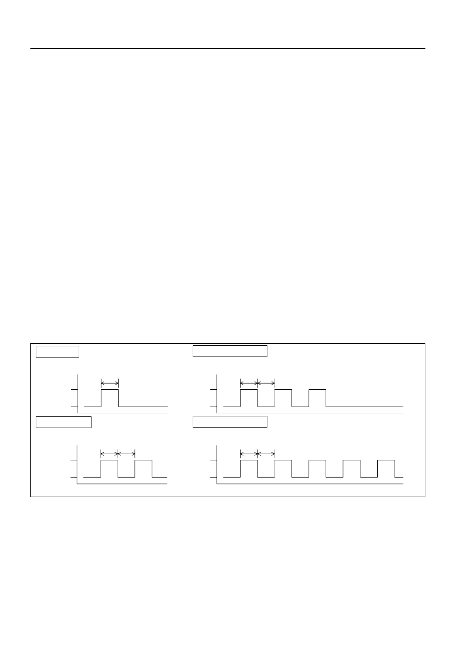
5.
LUGGAGE COMPARTMENT DOOR LOCK ASSY
(a)
Inspect the door lock motor operation.
Standard:
Measuring condition
Operation
Battery positive – Terminal 1
Battery negative – Lock body
Open
If the operation is not as specified, replace the door lock assem-
bly.

73085–01
73–6
–
THEFT DETERRENT & DOOR LOCK
WIRELESS DOOR LOCK CONTROL SYSTEM
2639
Author:
Date:
2002 CAMRY REPAIR MANUAL (RM881U)
WIRELESS DOOR LOCK CONTROL SYSTEM
ON–VEHICLE INSPECTION
1.
CHECK WIRELESS DOOR LOCK CONTROL FUNCTION
HINT:
The switch described in this text is a switch for transmitting (LOCK switch and UNLOCK switch), built in the
door control transmitter.
(a)
Vehicle’s initial condition (condition of wireless control possible)
No key in the ignition key cylinder
All doors closed (door open indicator off)
All doors locked
(b)
Check the basic function.
(1)
Check whether the LED lights up 3 times when each switch is pressed 3 times.
HINT:
In case that the LED does not light up when the switch has been pressed 3 times or more, it may be caused
by the dead battery.
(2)
In the remote control operational area, check that all the doors will lock or unlock when the switch
has been pressed for approximately 1 second. It is, however, not the case where the key is in
the ignition key cylinder or any of the doors is open.
HINT:
The UNLOCK operation is possible even when any of the doors is open.
(3)
Check that the luggage compartment door opens when the trunk switch has been pressed for
1 second (the operation is possible even when a door is open).
(c)
Check the automatic locking function.
(1)
Check that all doors will automatically lock as long as any of the doors has not been opened or
all doors have not been locked within approximately 30 seconds after all doors are unlocked by
pressing the switch.
(2)
Under the above condition, the automatic locking function will not work if any of the doors has
been opened or all doors have been locked within approximately 30 seconds.
(d)
Check the switch operation fail–safe function.
(1)
Check that doors are not locked or unlocked by the switch while the key is in the ignition key cylin-
der. However, the time of the discrimination code registration mode is excepted.
(e)
Check the chattering prevention function.
(1)
Check that the corresponding operation will be done only once but not repeat continuously when
the switch has been kept pressing. However, if the operations are carried out by approximately
1 second interval, from the time to release the switch till the time to press it again, check that a
corresponding operation to the switch that will be pressed next will be carried out.
(f)
Check the repeat function.
(1)
Check that all doors will automatically lock once again in 1 second after the lock switch has been
pressed while the move of the driver’s door control knob, which is in unlocking state, is being
blocked forcibly.
(g)
Check the operation stop function when a door is open or not completely close.
(1)
Check that doors are not locked or unlocked by the switch while any of the doors is open or not
completely close. However, tunk lock doors and to open the tunk are possible.

B58961
B59140
D13
–
THEFT DETERRENT & DOOR LOCK
WIRELESS DOOR LOCK CONTROL SYSTEM
73–7
2640
Author:
Date:
2002 CAMRY REPAIR MANUAL (RM881U)
(h)
Check the hazard flashing and buzzer sounding function (answer back).
(1)
Check that the hazard lights will flash and also the buzzer will sound once (when locked) or twice
(when unlocked) simultaneously with all doors’ locking or unlocking operation, when the switch
is pressed.
2.
CHECK WIRELESS CONTROL RECEIVER
(a)
Disconnect the D3 receiver connector and check that the
connector on the wire harness side.
(b)
Check the voltage and continuity of each terminal of the
wire harness side connector.
Standard :
Symbols (Terminal No.)
Wiring color
Condition
Specification
GND (D13–1)
⇔
Body ground
W–B
Constant
Continuity
+B (D13–5)
⇔
Body ground
R
Constant
10 – 14 V
HINT:
If the value is not as specified, the wire harness side may be de-
fective.
(c)
Using an oscilloscope, connect the receiver connector
and check the voltage.
Standard :
Symbols (Terminal No.)
Wiring color
Condition
Specification
RDA (D13–2)
⇔
Body ground
L–W
All door is closed
→
Door control transmitter ON
Below 1 V
→
6 – 7 V
→
Below 1 V
HINT:
If the value is not as specified, the wire harness side may be de-
fective.
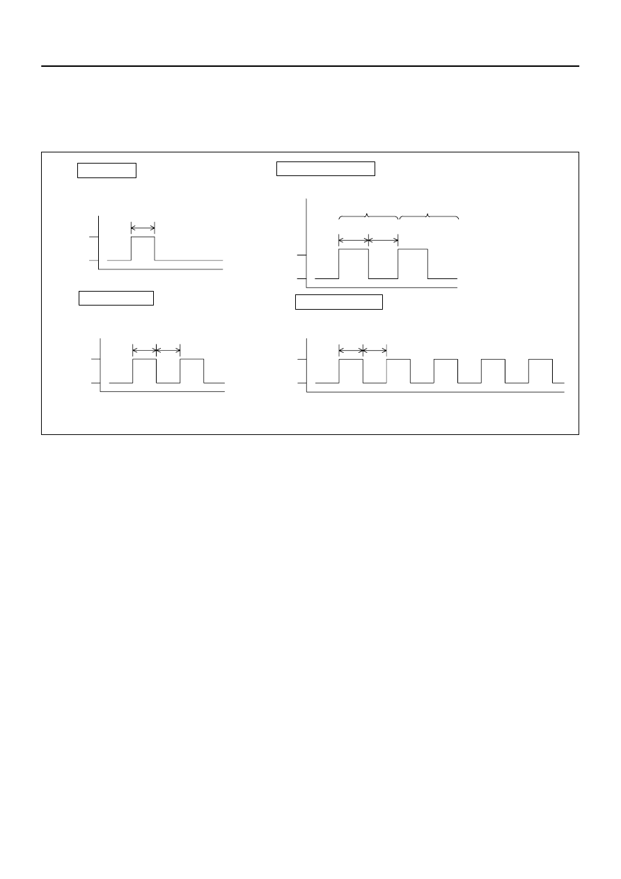
73084–01
B50826
ON–LOCK operation: 1 time
Add Mode
Rewrite Mode
ON–LOCK operation: 2 times
Confirmation Mode
ON–LOCK operation: 3 times
Prohibition Mode
ON–LOCK operation: 5 times
Approx. 1 sec.
Approx.
1 sec.
Approx.
1 sec.
Approx.
1 sec.
Approx.
1 sec.
Approx.
1 sec.
Approx.
1 sec.
ON
LOCK
ON
LOCK
ON
LOCK
ON
LOCK
73–8
–
THEFT DETERRENT & DOOR LOCK
DOOR CONTROL TRANSMITTER
2641
Author:
Date:
2002 CAMRY REPAIR MANUAL (RM881U) Corrected 8/05/02 – MH
DOOR CONTROL TRANSMITTER
REPLACEMENT
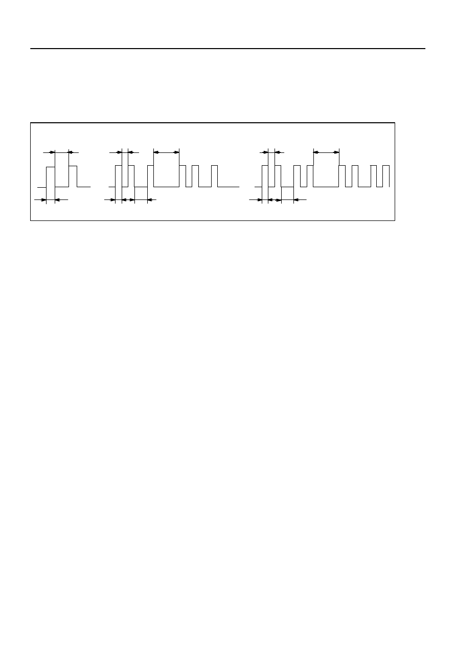
1.
REGISTRATION OF RECOGINITION CODE
HINT:
The add mode is used to retain already registered codes while registering new recognition codes. This
mode is used when adding a transmitter. If the number of registered codes exceeds 4, previously regis-
tered codes will be correspondingly erased in order, starting from the first registered code.
The rewrite mode is used to erase all the previously registered codes and register only new recognition
codes. This mode is used when exchanging the transmitter or the door control receiver with new one.
The prohibition mode is used to erase all the registered codes and cancels the wireless door lock func-
tion. Use this mode when the transmitter is lost.
The confirmation mode is for confirming how many recognition codes have already been registered
before an additional registration of a recognition code.
(a)
The vehicle should be in the following conditions.
(1)
The key is not inserted in the ignition key cylinder.
(2)
Driver’s door is OPENED. (The other doors are CLOSED)
(3)
Driver’s door is UNLOCKED.
(b)
Perform the followings after the above operations.
(1)
Insert and remove the key from the ignition key cylinder twice within 5 seconds.
(2)
After the above operations, close and open the driver door twice within 40 seconds. Then insert
the key into the ignition key cylinder and remove it.
(3)
After the above operations, close and open the driver door twice within 40 seconds. Then insert
the key into the ignition key cylinder and close the door.
(4)
Turn the ignition switch from LOCK to ON and back to LOCK at approximately. 1 second interval
1 to 5 times to select the mode. Then remove the key from the ignition key cylinder.
NOTICE:
If the number of the ON–LOCK operation of the ignition switch is 0, 4 or 6 or more, the operation will
finish without any signs.
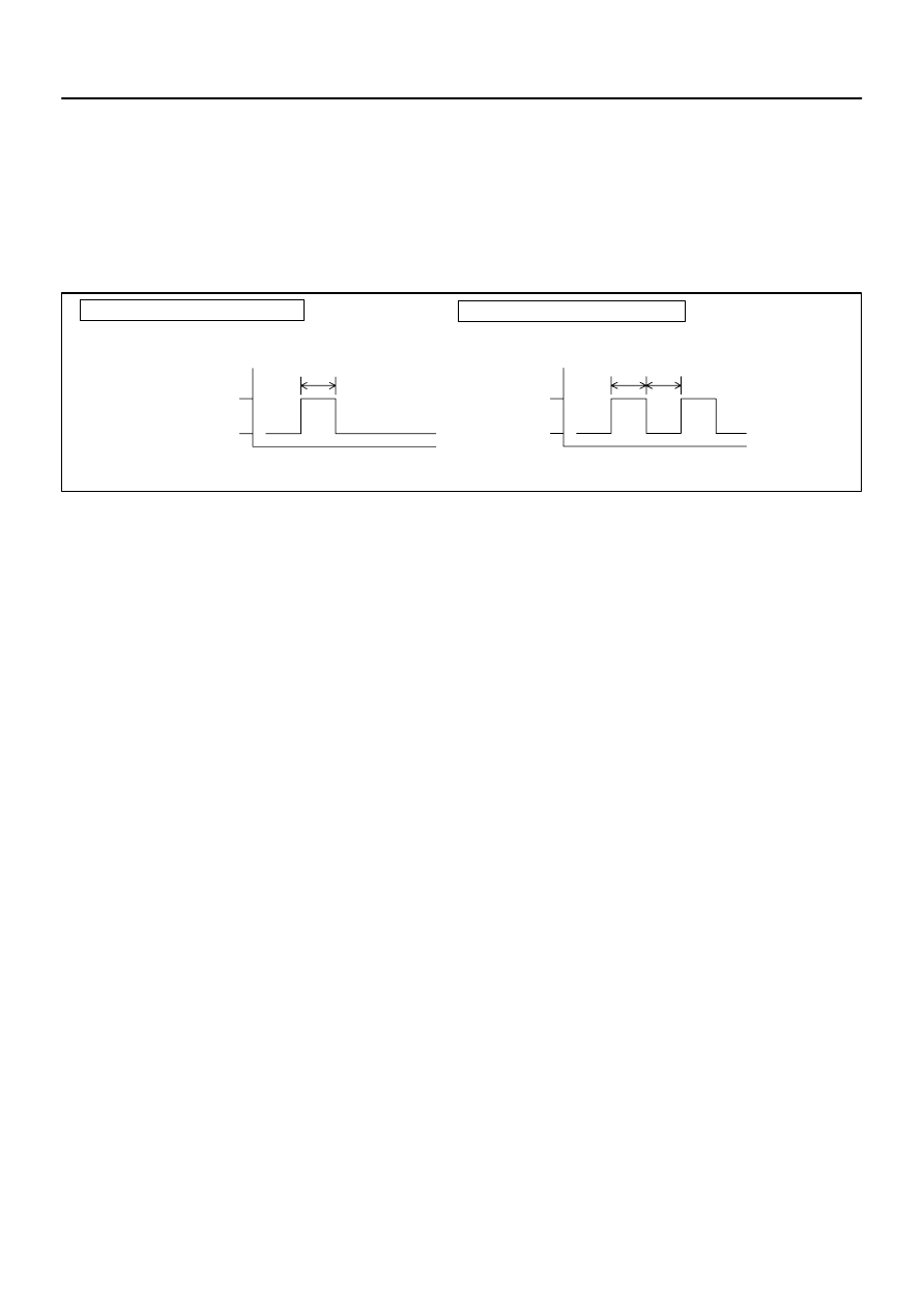
B50827
Confirmation Mode
Add Mode
Prohibition Mode
Rewrite Mode
LOCK
LOCK
LOCK
LOCK
UNLOCK
UNLOCK
UNLOCK
UNLOCK
Approx.
Approx.
1 sec.
1 sec.
1 sec.
1 sec.
1st time
2nd time
2 sec.
2sec.
Approx. Approx.
Approx.
Approx.
Approx.
1 sec.
–
THEFT DETERRENT & DOOR LOCK
DOOR CONTROL TRANSMITTER
73–9
2642
Author:
Date:
2002 CAMRY REPAIR MANUAL (RM881U) Corrected 8/05/02 – MH
(5)
Check that the MPX body ECU automatically performs the LOCK–UNLOCK operation within 3
seconds to inform the operator of a selected mode.
HINT:
In the confirmation mode as shown in the illustration, when the LOCK–UNLOCK operation is performed
twice, it means that 2 types of recognition codes are registered.
NOTICE:
In the confirmation mode, if the number of the registration code is 0, the ON–LOCK operation is auto-
matically performed 5 times.
HINT:
If the prohibition mode and confirmation mode are selected, the registration of the recognition code is com-
pleted at this time.
B50828
LOCK–UNLOCK Occurs Once
LOCK–UNLOCK Occurs Twice
Registration of recognition code has been completed.
Registration of recognition code has failed.
Approx.
1 sec.
LOCK
UNLOCK
1 sec.
1 sec.
LOCK
UNLOCK
Approx.
Approx.
73–10
–
THEFT DETERRENT & DOOR LOCK
DOOR CONTROL TRANSMITTER
2643
Author:
Date:
2002 CAMRY REPAIR MANUAL (RM881U) Corrected 8/05/02 – MH
(c)
Register a transmitter.
(1)
Within 40 seconds after the add mode or the rewrite mode has been selected, press the LOCK
and UNLOCK switches on the transmitter simultaneously for 1.0 – 1.5 seconds.
(2)
Within 3 seconds, press either one of the switches for more than 1.0 second.
(3)
Within 3 seconds, the LOCK–UNLOCK operation will be automatically performed once if the reg-
istration of the recognition code of the transmitter has been completed correctly. If the LOCK–
UNLOCK operation is performed twice, the registration of the recognition code has failed. Per-
form the registration procedure from the beginning once again.
(4)
When continuing the registration, register the next transmitter within 40 seconds after the pre-
vious registration.
HINT:
4 types of recognition codes can be registered at once.
(d)
If even one of the following conditions is satisfied, the registration of the recognition code is completed.
(1)
40 seconds have elapsed since the response of the door control relay.
(2)
The driver’s door is opened.
(3)
The key plate is inserted in the ignition key cylinder.
(4)
4 types of recognition codes are registered at one time.
7307U–02
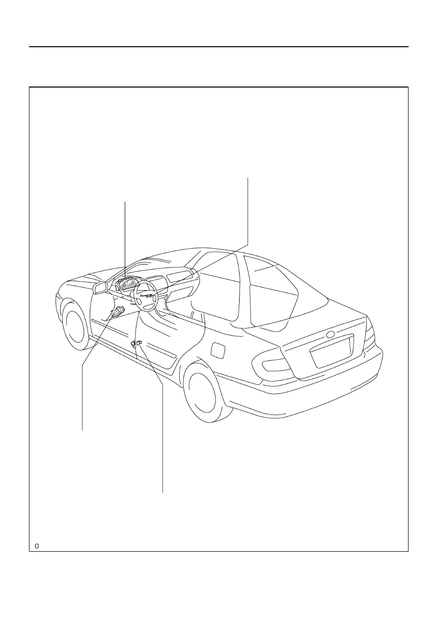
B56177
Unlock Warning Swicth Assy
Combination Meter (Warning Buzzer)
Front Door Courtesy Lamp Switch
Instrument Panel J/B (Body ECU)
–
THEFT DETERRENT & DOOR LOCK
KEY UNLOCK WARNING SYSTEM
73–11
2644
Author:
Date:
2002 CAMRY REPAIR MANUAL (RM881U)
KEY UNLOCK WARNING SYSTEM
LOCATION
7307V–02
B56678
B58627
B6
B7
B8
B6
B7
B8
73–12
–
THEFT DETERRENT & DOOR LOCK
KEY UNLOCK WARNING SYSTEM
2645
Author:
Date:
2002 CAMRY REPAIR MANUAL (RM881U)
ON–VEHICLE INSPECTION
1.
FUNCTION CHECK
(a)
Check that the key reminder warning buzzer will sound.
(1)
With the driver’s door close, insert the key into the ignition switch lock cylinder, and then turn the
key to the LOCK or ACC.
(2)
Then, check that the buzzer will sound intermittently if the driver’s door is opened.
(b)
Check that the key reminder warning buzzer will stop.
(1)
Check that the buzzer will stop if any of the following operations is done while the buzzer is sound-
ing.
(2)
Close the driver’s door (front door courtesy lamp switch assembly is off).
(3)
Turn the ignition switch ON.
(4)
Pull out the key from the ignition switch lock cylinder.
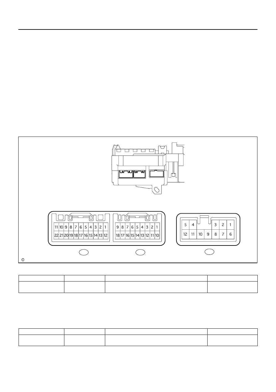
2.
CHECK INSTRUMENT PANEL JUNCTION BLOCK ASSY (BODY ECU) (LEFT SIDE)
(a)
Disconnect the B6 body ECU connector.
(b)
Check the connector terminal continuity.
Standard:
Symbols (Terminal No.)
Wiring color
Condition
Specified condition
KSW (B6–19)
⇔
Body ground
L
⇔
Body ground
No key in ignition switch lock cylinder
→
Key inserted
No continuity
→
Continuity
HINT:
If the value is not as specified, check and replace the wire harness side.
(c)
Reconnect the connector.
(d)
Check the connector terminal voltage.
Standard:
Symbols (Terminal No.)
Wiring color
Condition
Specified condition
DCTY (B8–1)
⇔
Body ground
R–G
⇔
Body ground
Driver’s door fully closed
→
Opened
10 – 14 V
→
0 V
HINT:
If the value is not as specified, check the instrument panel J/B side.
B58626
2G
2D
2H
2A
2K
2R
2B
2C
2K
2A
2D
2F
2J
2H
2G
2E
2E
2B
2F
2J
2C
11 12 13 14 15 16
17 18 19 20
1
2 3 4
5
6
7
8 9 10
From Instrument Panel Wire
–
THEFT DETERRENT & DOOR LOCK
KEY UNLOCK WARNING SYSTEM
73–13
2646
Author:
Date:
2002 CAMRY REPAIR MANUAL (RM881U)
3.
CHECK INSTRUMENT PANEL JUNCTION BLOCK ASSY (BODY ECU) (REAR SIDE)
(a)
Disconnect the 2F and 2G connectors.
(b)
Check the voltage and continuity between the connector terminals.
Standard:
Symbols (Terminal No.)
Wiring color
Condition
Specified condition
B (2F–7)
⇔
Body ground
R
⇔
Body ground
Constant
10 – 14 V
BDR1 (2G–14)
⇔
Body ground
L–W
⇔
Body ground
Constant
10 – 14 V
GND (2R–8)
⇔
Body ground
W–B
⇔
Body ground
Constant
Continuity
HINT:
If the value is not as specified, check and replace the wire harness side.

7307W–02
73–14
–
THEFT DETERRENT & DOOR LOCK
KEY UNLOCK WARNING SYSTEM
2647
Author:
Date:
2002 CAMRY REPAIR MANUAL (RM881U)
PROBLEM SYMPTOMS TABLE
Symptom
Suspected Area
See page
Key unlock warning buzzer does not sound
1. Unlock warning switch
2. Front door courtesy lamp switch
3. Instrument panel J/B (Body ECU)
4. Combination meter
5. Wire harness
73–15
73–15
73–12
–
–
7307X–02
B51903
ON
OFF
B32309
–
THEFT DETERRENT & DOOR LOCK
KEY UNLOCK WARNING SYSTEM
73–15
2648
Author:
Date:
2002 CAMRY REPAIR MANUAL (RM881U)
INSPECTION
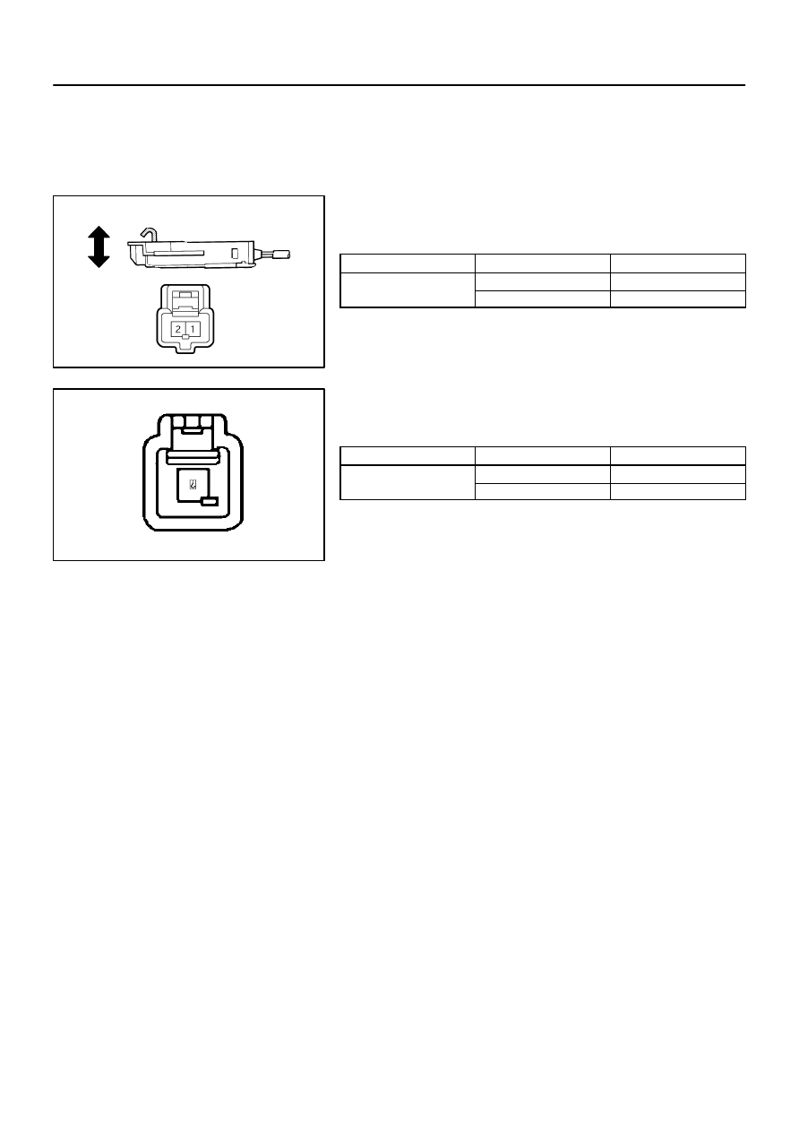
1.
INSPECT UN–LOCK WARNING SWITCH ASSY
(a)
Check the switch continuity.
Standard:
Terminal No.
Condition
Specification
1
⇔
2
Switch pressed in
Continuity
1
⇔
2
Switch not pressed in
No continuity
If the continuity is not as specified, replace the switch.
2.
INSPECT COURTESY LAMP SWITCH
(a)
Check the switch continuity.
Standard:
Terminal No.
Condition
Specification
1
⇔
Switch body
FREE
Continuity
1
⇔
Switch body
PUSH
No continuity
If the continuity is not as specified, replace the switch.

7307L–01
73–16
–
THEFT DETERRENT & DOOR LOCK
THEFT DETERRENT SYSTEM
2649
Author:
Date:
2002 CAMRY REPAIR MANUAL (RM881U)
THEFT DETERRENT SYSTEM
ON–VEHICLE INSPECTION
1.
DESCRIPTION OF AUTOMATIC ALARMING CONDITION
Condition
Description
Disarming condition
Alarm system is not set. (Theft detection is not performed)
Arming preparation condition (30 sec.)
Preparing for the alarm system being set after the system setting conditions
are satisfied. (Theft detection is not performed)
Arming condition
Alarm system is set.
(Theft detection is performed)
Alarming condition
Alarming with hazard warning lights and horns by detecting a theft.
(Alarming is kept for 60 sec.)
2.
INSPECT AUTOMATIC ALARM OPERATION
HINT:
Wireless operation written in this text shows the operation of the ”LOCK/UNLOCK” and the door control
transmitter switch operation and each operation as well.
All doors written in this text shows ”4–door”.
(a)
Disarming condition
→
arming preparation condition (with no key in the ignition switch lock cylinder).
(1)
Lock all doors via the wireless operation when all doors, hood and back door are closed.
(b)
Arming preparation condition
→
Arming condition (30 seconds have elapsed since the disarming prep-
aration condition)
(c)
Arming condition
→
Alarming condition (alarming functions when any of the following conditions is sa-
tisfied)
(1)
Any of the doors or hood is open.
(2)
Any of the doors is unlocked by any ways except the wireless operation.
(3)
The hood is open.
(4)
The battery is reconnected.
(5)
The ignition terminal is short–circuited.
(6)
The self power siren sounds at the same time when the battery is disconnected.
(d)
Alarming (arming) condition
→
Disarming condition (if step (1) is satisfied during the arming condition,
it enters into the disarming condition. Also, if step (1) is satisfied during the alarming condition, it stops
alarming and enters into the disarming condition.)
(1)
All doors are unlocked by the wireless operation.
(e)
Alarming condition (after the condition (c) has been satisfied, it starts the alarming condition, such as
the hazard light’s flashing, dome in lamp’s flashing, horn’s sounding and security siren’s sounding for
60 seconds, and the doors are locked forcibly (If any of the doors is unlocked).
HINT:
It transfers into the arming condition 60 seconds after the alarming.
(f)
Arming preparation condition
→
Disarming condition (if any of the following conditions is satisfied dur-
ing the arming preparation condition, it enters into the disarming condition.
(1)
Any of all doors is unlocked.
(2)
Any of all doors and the back door is open.
(3)
The hood is open.
(4)
The key is inserted into the ignition switch lock cylinder.
(5)
The battery is reconnected.
(6)
The ignition switch is turned ON.

–
THEFT DETERRENT & DOOR LOCK
THEFT DETERRENT SYSTEM
73–17
2650
Author:
Date:
2002 CAMRY REPAIR MANUAL (RM881U)
3.
CHECK OUTPUTS OF INDICATOR
(a)
Check that the indicator light comes on in the following condition.
Condition
Indicator light
Disarming condition (Immobilizer unset)
OFF
Disarming condition
(Immobilizer set)
Blink
Arming preparation condition
ON
Arming condition
Blink
Alarming condition
ON
4.
THEFT DETERRENT SYSTEM
When the system is set to the theft deterrent mode and any of the following conditions are met, the system
sounds the horns and flashes the headlights and the taillights for approximately 1 minute. At the same time
the system locks all doors (If all doors are not locked at once, the system repeats door locking operation
every 0.38 seconds during the one minute alarming time).
There are 2 modes in this system; one is active mode and another is passive mode.
All initial settings are performed in the active mode. It can be switched to the passive mode by a specified
operation.
Any of the doors (including the engine hood and luggage compartment door) is unlocked or opened
without the key. *1
The battery terminal is disconnected and reconnected.
The system receives a panic signal from remote keyless entry. *2
*1: Only active arming mode.
*2: When the ignition key is not inserted in the key cylinder.
There are 4 conditions in this system which are disarming condition, disarming preparation condition, arming
condition and alarming condition.
(a)
Disarming condition:
(1)
When a user is near the vehicle.
(2)
When the alarming function does not operate.
(3)
When the theft deterrent function does not operate.
(b)
Disarming preparation condition:
(1)
Time from a user locks a door to be leaves the vehicle.
(2)
Time until transferring to the disarming condition.
(3)
When the theft deterrent function does not operate.
(c)
Arming condition:
(1)
When a user leaves the vehicle completely.
(2)
When the theft deterrent function operates.
(d)
Alarming condition:
(1)
In this condition, once a theft is detected, lights will flash and horns will sound to let people around
the vehicle know about the theft.
Refer to the table for alarming method or time.
Horn
Al
i
th d
Security horn
Alarming method
Headlight
Taillight
Alarming time
60 seconds
Alarming output
Continuous 0.40 sec. (ON)
0.40 sec. (OFF)
In the arming condition, when either of doors is unlocked and no key is in the key cylinder, force lock signal
is output.
Disarming condition
Any of the following conditions is met
When all doors and engine hood are closed, lock all the doors using a key.
When all doors and engine hood are closed, lock all the doors using wireless remote function.
When all doors and engine hood are closed, open and close either of doors and engine hood
then close and lock all doors and engine hood.
Disarming preparation condition
The following condition is met
After 30 seconds have elapsed when the en-
gine hood
is closed and all doors are locked.
Any of the following conditions is met
Close and open one of doors and
engine hood.
Lock and unlock either of doors.
Insert a key into the ignition key cylinder.
Reconnect the battery.
Arming condition
Any of the following conditions is met
Unlock the locked doors using the wireless
remote function.
Unlock the locked doors using the key.
Insert the key into the ignition key cylinder
and turn the ignition key ON.
Any of the following conditions is met
Either of closed doors opens.
Either of locked doors is unlocked by any
way other than key or wireless remote
function.
The closed engine hood is opened.
The battery is reconnected.
Ignition switch is turned to ON.
Alarming condition
Any of the following conditions is met
Unlock the locked doors using the wireless
remote function.
Unlock the locked doors using the key.
Insert the key into the ignition key cylinder
and turn the ignition key ON.
In this mode, once a theft is detected, lights
will flash and horns will sound to let people
around the vehicle know about it.
The above specified alarming time passes.
(No key inserted in ignition cylinder.)
73–18
–
THEFT DETERRENT & DOOR LOCK
THEFT DETERRENT SYSTEM
2651
Author:
Date:
2002 CAMRY REPAIR MANUAL (RM881U)
5.
ACTIVE ARMING MODE

–
THEFT DETERRENT & DOOR LOCK
THEFT DETERRENT SYSTEM
73–19
2652
Author:
Date:
2002 CAMRY REPAIR MANUAL (RM881U)
INDICATOR LIGHT OUTPUT:
Condition
Indicator light
Disarming condition
OFF
Disarming preparation condition
ON
Arming condition
OFF
Alarming condition
ON
HINT:
Even in the disarming condition, the indicator light flashes (due to a signal output from immobilizer system).
The indicator always flashes by receiving a signal from the immobilizer system at any time in the arming
condition.
Flashing frequency:
0.2 seconds (ON)
1.8 seconds (OFF)
6.
PASSIVE ARMING MODE
This mode can be switched by the specified operation.
All initially set modes (when shipped from factory) are active mode. (No passive mode)
Perform any of the following and the system will go to Disarmed state (B):
Remove the key from the ignition, close the driver’s door, then the ignition be OFF.
Disarmed state (A)
Perform any of the followings and the system
will return to Disarmed state (A):
Push the unlock switch on the wireless
remote.
Put the key in the lock on the driver’s or the
passenger door and turn it towards the unlock.
Put the key in the ignition.
Reconnect the battery.
Turn the ignition from OFF to ON.
Disarmed state (B)
Perform any of the following and the system
will go to Arming preparation:
Close all the doors.
Perform any of the following
and the system will return to
Disarmed state (B):
Open any of the doors, the
hood.
Arming preparation
Perform the following and the
system will go to Armed state:
Allow 30 seconds to elapse
with all the doors, and hood
closed.
Perform any of the followings
and the system will return to
Disarmed state (A):
Push the unlock switch on
the wireless remote.
Put the key in the lock on
the driver’s or the passenger
door or the luggage door and
turn it towards the unlock.
Put the key in the
ignition and turn it ON.
Armed state
Perform any of the followings
and the system will go on to
Alarm sounding:
Open any of the doors and
allow the entry delay time
to pass.
Open the hood.
Open the luggage door with
something other than the
key or wireless remote.
Reconnect the battery.
Perform any of the following and
the system will return to Dis-
armed state (A):
Push the unlock switch on the
wireless remote.
Put the key in the lock on the
driver’s or the passenger door or
the luggage door and turn it to-
wards the unlock.
Put the key in the ignition.
Reconnect the battery.
Turn the ignition from OFF to
ON.
73–20
–
THEFT DETERRENT & DOOR LOCK
THEFT DETERRENT SYSTEM
2653
Author:
Date:
2002 CAMRY REPAIR MANUAL (RM881U)
Perform any of the following
and the system will return to
Armed state:
The alarm sounding period
passes.
Alarm sounding
Perform any of the followings
and the system will return to
Disarmed state (A):
Push the unlock switch on
the wireless remote.
Put the key in the lock on
the driver’s or the passenger
door or the luggage door and
turn it towards the unlock.
Put the key in the ignition
and turn it ON.
–
THEFT DETERRENT & DOOR LOCK
THEFT DETERRENT SYSTEM
73–21
2654
Author:
Date:
2002 CAMRY REPAIR MANUAL (RM881U)
Door
Indicator
Alarming output
System condition
Arming condition
Alarming
condition
Entry delay time
Close
Open
ON
OFF
ON
OFF
73–22
–
THEFT DETERRENT & DOOR LOCK
THEFT DETERRENT SYSTEM
2655
Author:
Date:
2002 CAMRY REPAIR MANUAL (RM881U)
HINT:
When either closed door is opened in the arming condition, entry delay occurs. (14 seconds)
During this time, the mode transfers to the disarming condition when the condition described above is met.
When the condition is not met, the system judges a theft and the mode transfers to the alarming condition.
INDICATOR LIGHT OUTPUT:
Condition
Indicator light
Disarming condition
OFF
Disarming preparation condition
ON
Arming condition
(Entry delay time)
OFF
(ON)
Alarming condition
ON
HINT:
Even in the disarming condition, the indicator light flashes (due to the signal output from immobilizer system).
The indicator always flashes by receiving the signal from the immobilizer system at any time in the arming
condition.
Flashing frequency:
0.2 seconds (ON)
1.8 seconds (OFF)
Transfer to active mode: In each passive mode, when ”disarming condition of active mode
→
disarming
preparation transfer condition” is met, the active mode transfers to each condition. In this case, active
mode continues until the disarming condition.
Passive mode when transfer condition is
met.
Active mode transfer condition
Disarming condition
Disarming preparation condition
Disarming preparation condition
Disarming preparation condition
Arming condition
(During entry delay time)
Arming condition
(After alarming time has elapsed, arming
condition)
Alarming condition
After alarming time has elapsed, arming
condition
Remove the ignition key from key cylinder.
All the doors and luggage compartment door
except engine hood
are closed and
unlocked.
Any of doors is locked and unlocked by turns
3 times by the key or remote control.
Driver’s side knob for door lock is locked and
unlocked 3 times.
Driver’s side door is opened.
The system starts force lock at once after 2
sec.
Driver’s side knob for door lock is unlocked.
Driver’s side door is closed and opened 2
times
Driver’s side knob for door lock is locked and
unlocked.
The system starts force lock at once after 2
secs.
PASSIVE MODE OFF
Driver’s side door is closed and opened 3
to 5 times
Driver’s side knob for door lock is locked and
unlocked.
The system starts force lock at once after 2
sec.
PASSIVE MODE ON
Within
30 sec.
Within
20 sec.
HINT:
Initial mode is PASSIVE MODE OFF.
If there is a different signal in the middle of changing. It is invalid.
*: Entry delay time
Input to the vehicle
Output from the vehicle
* 0 sec.
4 times
5 times
3 times
* 14 sec.
* 30 sec.
Within
2 sec.
Within
2 sec.
–
THEFT DETERRENT & DOOR LOCK
THEFT DETERRENT SYSTEM
73–23
2656
Author:
Date:
2002 CAMRY REPAIR MANUAL (RM881U)
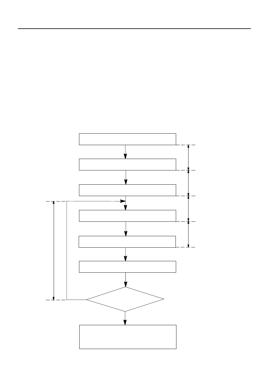
7.
CHANGING METHOD OF PASSIVE MODE
(ON or OFF)
73086–01
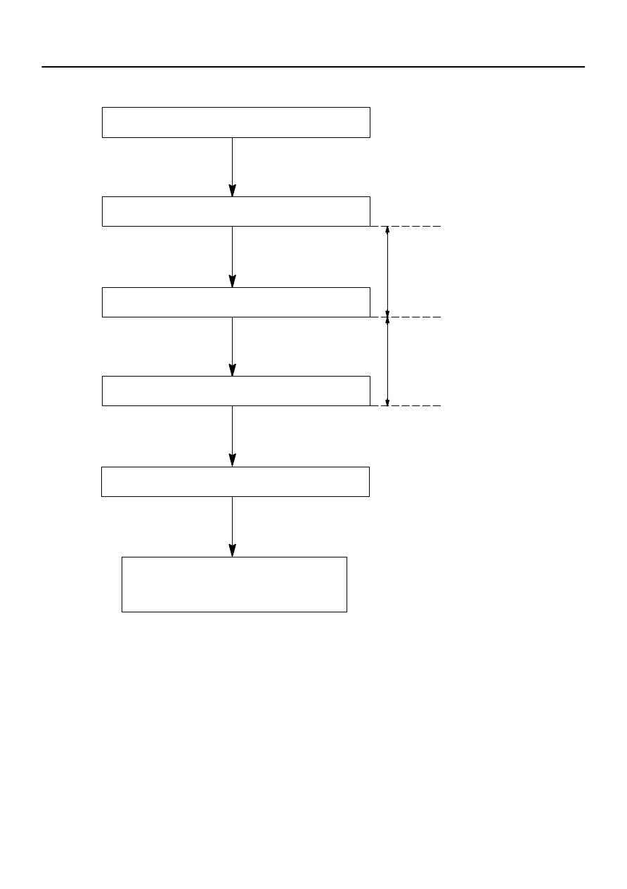
START
Insert the key in the key cylinder.
Under registration
Registration completion
Remove the key.
Will you register the
next key?
No
Security indicator continues blinking
until the first key is inserted. The indi-
cator lights up after the key registra-
tion.
Security indicator ON
Security indicator OFF
END
Yes
Security indicator light is ON
(After the last key (sub–key) has
been registered, the indicator
remains OFF until removing the
key. And after removing the key,
the indicator blinks.)
73–24
–
THEFT DETERRENT & DOOR LOCK
ENGINE IMMOBILISER SYSTEM
2657
Author:
Date:
2002 CAMRY REPAIR MANUAL (RM881U)
ENGINE IMMOBILISER SYSTEM
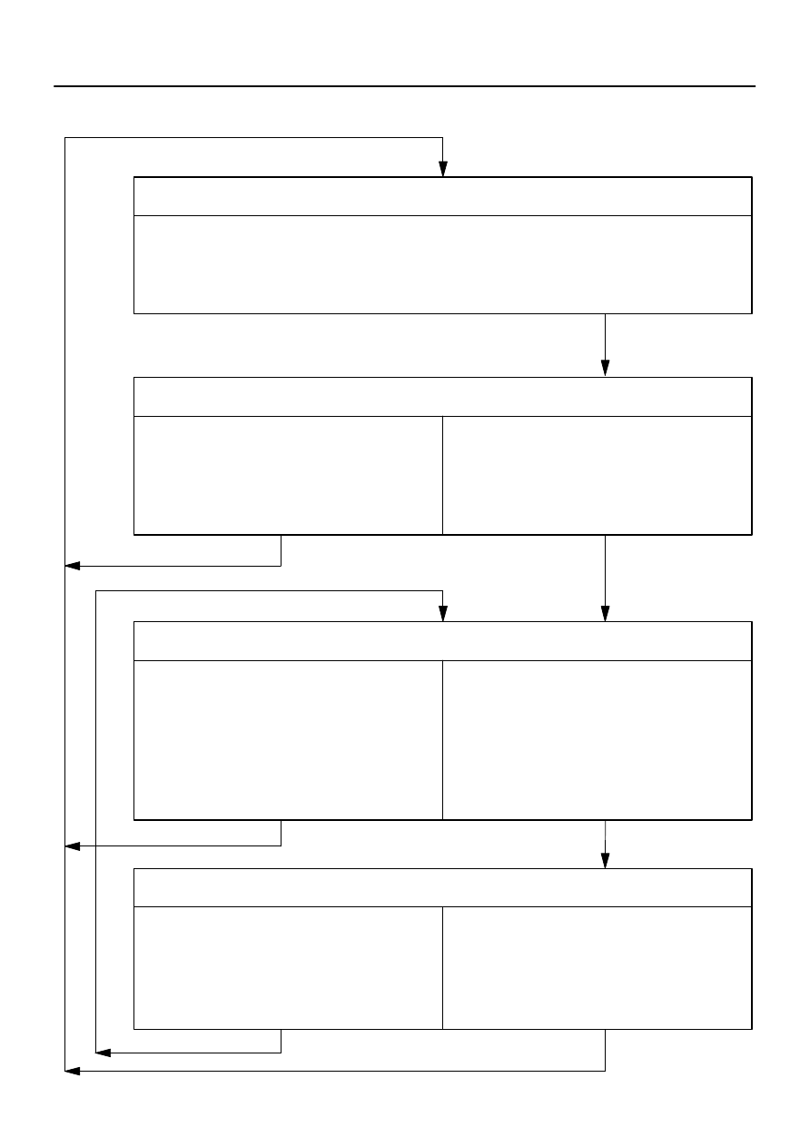
REGISTRATION
1.
KEY REGISTRATION IN AUTOMATIC REGISTRATION
(a)
Registration of a new transponder key.
This must be done when you install a new ECM.
The new ECM is in the automatic key code registration mode. The number of key codes for this
ECM is already fixed, and so it can be registedered.
On this type of vehicle, up to 3 key codes can be registered.
In the automatic registration mode, the key registered last becomes the sub–key.
1.2 Sec.
0.8 Sec.
0.25 Sec. 0.5 Sec.
0.25 Sec.
1 Sec.
Blinks
Code 2–1
Code 2–2
0.25 Sec.
0.25 Sec.0.5 Sec.
1 Sec.
–
THEFT DETERRENT & DOOR LOCK
ENGINE IMMOBILISER SYSTEM
73–25
2658
Author:
Date:
2002 CAMRY REPAIR MANUAL (RM881U)
HINT:
When no key is inserted in the key cylinder in the automatic registration mode, the security indicator
always lights on.
When the immobiliser system operates normally and the key is pull out, the security indicator blinks.
When key code registration could not be performed in the automatic registration mode, code 2–1 is
output from the security indicator. And when inserting the already registered key, code 2–2 is output.
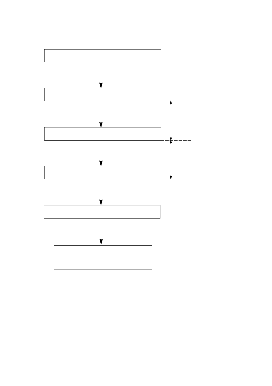
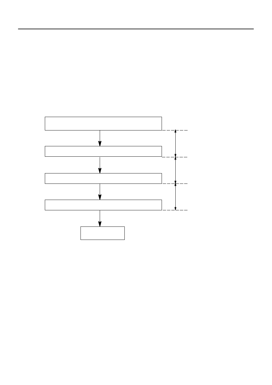
(b)
Automatic registration mode completion
If finishing the mode forcibly after registering more than 1 key codes in the automatic registration mode,
perform the following procedures.
After 1 more key code has been registered with the master key, perform step (1) or (2) without pulling
the key out or inserting the already registered key.
(1)
Depress and release the brake pedal 5 times or more within 15 seconds.
(2)
With the hand–held tester, require the automatic registration mode completion.
Will you register the
next key?
No
Yes
Insert the already registered master key in the
key cylinder
Depress and release the acceleration pedal 5
times.
Depress and release the brake pedal 6 times,
and remove the master key.
Insert a key to be registered in key cylinder.
Depress and release the acceleration pedal 1
time. (Security indicator blinks)
The registration mode is complete when pulling
out the key and depressing and releasing the
brake pedal once or more within 10 secs. after
indicator has been off or 10 sec. have passed.
Within 10 sec.
Within 15 sec.
Within 20 sec.
Within 10 sec.
Within 10 sec.
After 60 sec. additional master key is registration
is complete. (Security indicator is OFF)
73–26
–
THEFT DETERRENT & DOOR LOCK
ENGINE IMMOBILISER SYSTEM
2659
Author:
Date:
2002 CAMRY REPAIR MANUAL (RM881U)
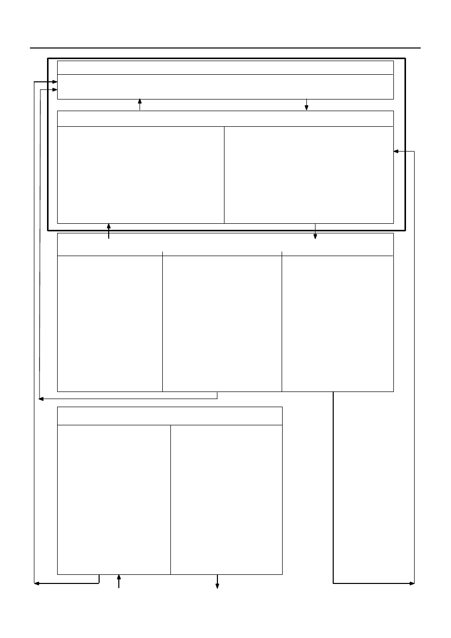
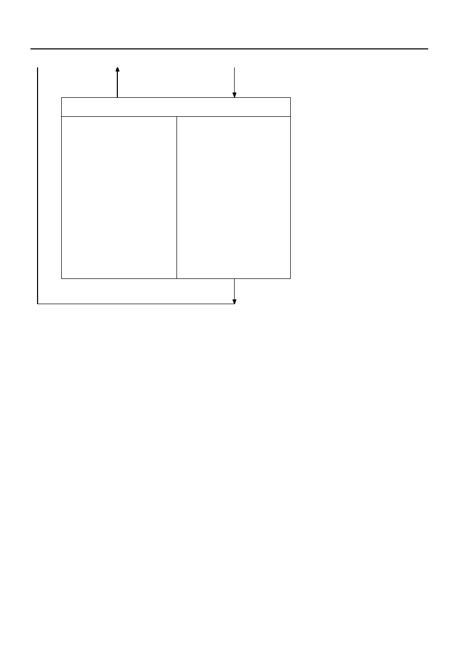
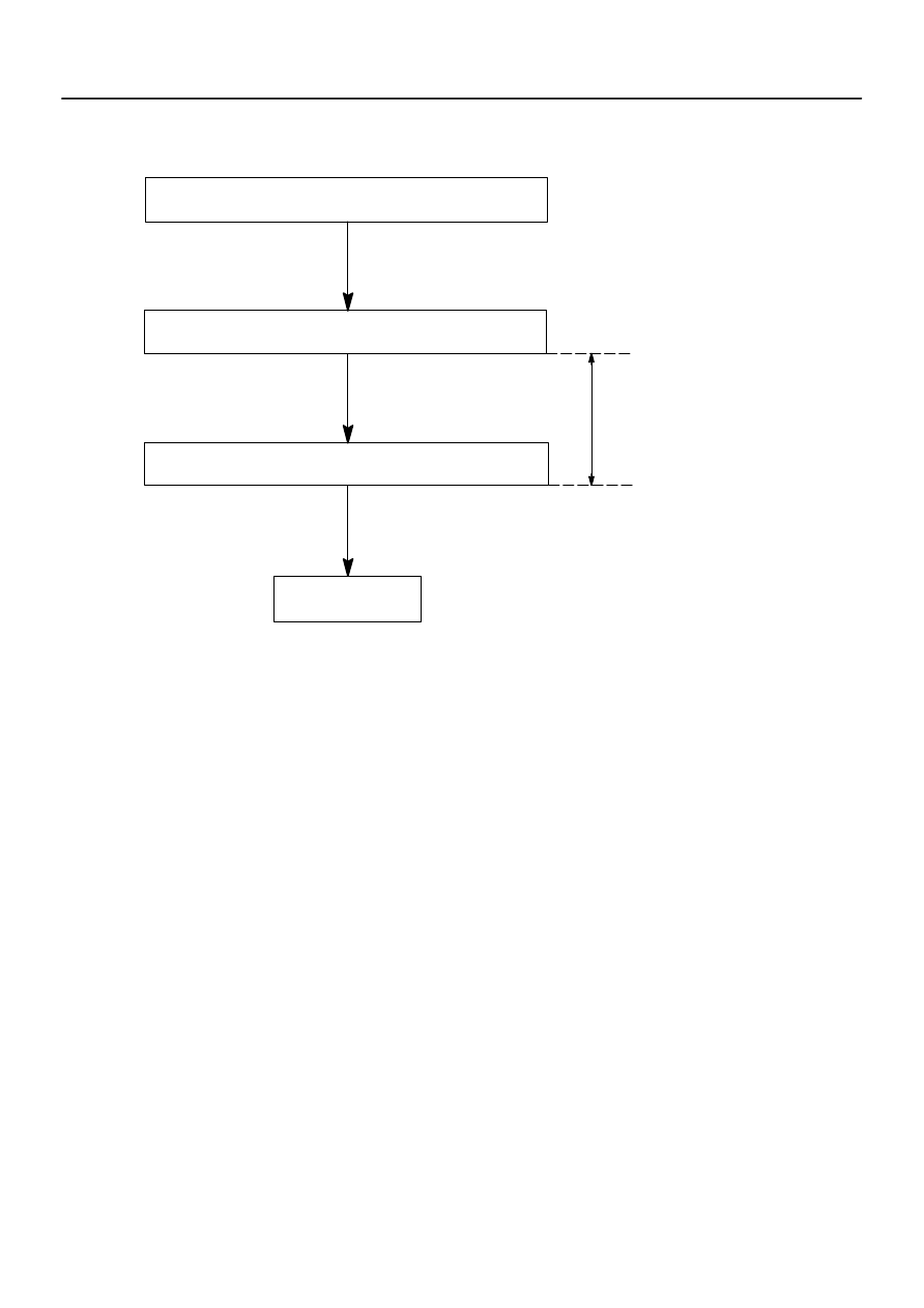
2.
REGISTRATION OF ADDITIONAL KEY
There are 2 ways for registration of additional master key; one way is depressing the brake pedal and accel-
eration pedal and the other way is using the hand–held tester.
HINT:
It is possible to register up to 7 master key codes including the already registered key code.
When any operation time described below is over, registration mode will be stopped forcibly.
When the next procedure is started while the timer is working, the timer stops working, then the next
timer starts.
When replacing ”Ignition Cylinder Key Set” or ”Lock Cylinder Set” and register according to the follow-
ing procedure using the original master key. However, after the registration of the additional master
key, the original master key and the original sub–key are not necessary any more, and there fore regis-
tration of those key codes should be deleted.
(1)
Depressing the brake pedal and acceleration pedal:
Insert the already registered master key in the key cylin-
der and turn the ignition switch ON.
Using the hand–held tester, select the master key
registration.
Remove the master key.
Insert a key to be registered in the key cylinder.
(Security indicator blinks)
After 60 sec., additional master key registration is
complete. (Security indicator OFF)
Within 20 sec.
Within 10 sec.
The registration mode is complete when pulling
out the key and depressing and releasing the
brake pedal once or more within 10 sec. after in-
dicator has been off or 10 sec. have passed.
HINT:
Follow the screen of the hand–held tester for more detailed procedure.
–
THEFT DETERRENT & DOOR LOCK
ENGINE IMMOBILISER SYSTEM
73–27
2660
Author:
Date:
2002 CAMRY REPAIR MANUAL (RM881U)
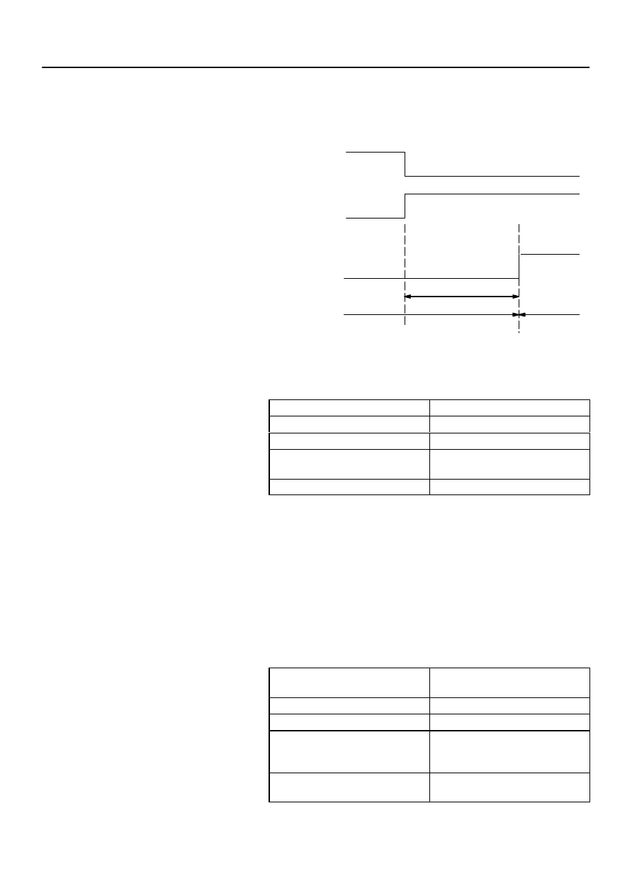
(2)
Using the hand–held tester:
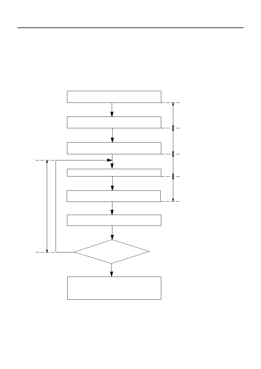
Will you register the
next key?
No
Yes
Insert the already registered master key in the
key cylinder
Depress and release the acceleration pedal 4
times.
Depress and release the brake pedal 5 times,
and remove the master key.
Insert key to be registered in key cylinder.
Depress and release the acceleration pedal 1
time. (Security indicator blinks)
Within 10 sec.
Within 15 sec.
Within 20 sec.
Within 10 sec.
Within 10 sec.
After 60 sec. additional sub–key is registered.
(Security indicator is OFF)
The registration mode completes when pulling
out the key and depressing and releasing the
brake pedal once or more within 10 sec. after in-
dicator has been off or 10 sec. have passed.
73–28
–
THEFT DETERRENT & DOOR LOCK
ENGINE IMMOBILISER SYSTEM
2661
Author:
Date:
2002 CAMRY REPAIR MANUAL (RM881U)
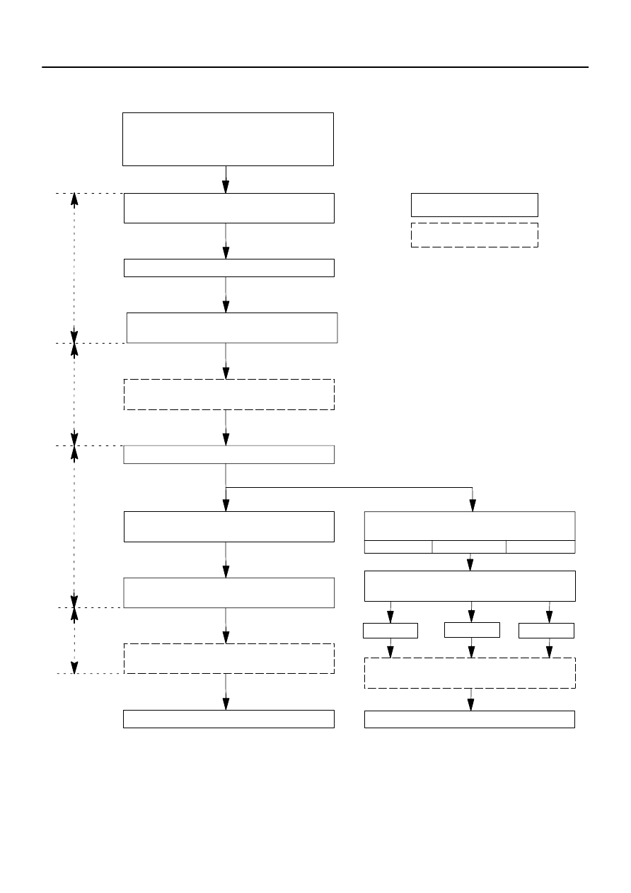
3.
REGISTRATION OF KEY NUMBER
There are 2 ways for registration of additional sub–key; one way is depressing the brake pedal and accelera-
tion pedal and the other way is using hand–held tester.
HINT:
It is possible to register up to 3 sub–key codes including the already registered key code.
When any operation time described below is over, registration mode will be stopped forcibly.
When the next procedure is started while the timer is working, the timer stops working, then the next
timer starts.
(1)
Depressing the brake pedal and acceleration pedal:
Insert the already registered master key in the key cylin-
der and turn the ignition switch ON.
Using the hand–held tester, select the sub–key
registration.
Remove the master key.
Insert a key to be registered in the key cylinder.
(Security indicator blinks)
After 60 sec., additional sub–key registration is
complete. (Security indicator OFF)
Within 20 sec.
Within 10 sec.
The registration mode is complete when pulling
out the key and depressing and releasing the
brake pedal once or more within 10 sec. after in-
dicator has been off or 10 sec. have passed.
HINT:
Follow the screen of the hand–held tester for more detailed procedure.
–
THEFT DETERRENT & DOOR LOCK
ENGINE IMMOBILISER SYSTEM
73–29
2662
Author:
Date:
2002 CAMRY REPAIR MANUAL (RM881U)
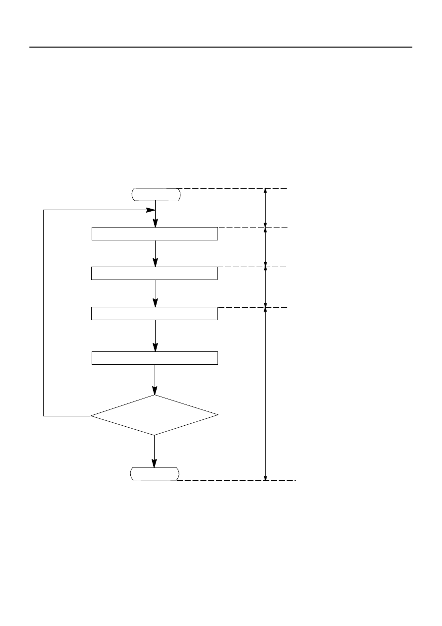
(2)
Using the hand–held tester:
1. Insert the already registered master key in the key
cylinder.
2. Depress and release the acceleration pedal 6 times.
3. Depress and release the brake pedal 7 times.
4. Remove the master key.
END
(Key code erased)
Within 15 sec.
Within 20 sec.
Within 10 sec.
HINT:
When the key cannot be pulled out in step 4, key code deletion is canceled.
73–30
–
THEFT DETERRENT & DOOR LOCK
ENGINE IMMOBILISER SYSTEM
2663
Author:
Date:
2002 CAMRY REPAIR MANUAL (RM881U)
4.
ERASURE OF KEY CODE
There are 2 ways for erasure of transponder key codes; one way is depressing the brake pedal and accelera-
tion pedal and the other way is using hand–held tester.
HINT:
Delete all the other master and sub–key codes than a master key code to use the erasing operation.
When using the key which was used for deletion, it is necessary to register the code again.
When any operation time described below is over, registration mode will be stopped forcibly.
When the next procedure is started while the timer is working, the timer stops working, then the next
timer starts.
(1)
Depressing the brake pedal and acceleration pedal:
1. Insert the already registered master key in the key
cylinder and turn the ignition switch ON.
2. Require the key code deletion on the hand–held tester.
(Security indicator blinks)
3. Remove the master key.
HINT:
When the key cannot be pulled out in step 3, key code deletion is canceled.
(Security indicator is OFF.)
Follow the screen of the hand–held tester for more detailed procedure.
END
(Key code erased)
Within 10 sec.
–
THEFT DETERRENT & DOOR LOCK
ENGINE IMMOBILISER SYSTEM
73–31
2664
Author:
Date:
2002 CAMRY REPAIR MANUAL (RM881U)
(2)
Using the hand–held tester:
Wyszukiwarka
Podobne podstrony:
73 Theft Deterrent and Door Lock
73 Anti Theft and Door Locks
73 Anti Theft and Door Locks
10010 HIGHLANDER TOYOTA and LEXUS door lock interface
Door lock repair
American Woodworker Drawer And Door Pulls (2)
75 Engine Hood and Door
VW Passat B5 Door Lock Mechanism Repair
14301 AURORA AURORA DOOR LOCK DIAGRAM
Theft Deterrent
6 SALINE LOCK AND INTRAVENOUS INFUSION POL
M39t1 Remote Keyless Entry and Anti theft System
M39t2 Remote Keyless Entry and Anti theft System
Grand Theft Auto IV The Lost and Damned
Paul D Numrich The Faith Next Door, American Christians and Their New Religious Neighbors (2009)
więcej podobnych podstron