
Troubleshooting and repair instructions
25 2081 95 12 57 11.1998 Modifications reserved Printed in Germany © Copyright J. Eberspächer GmbH & Co. C41
Eberspächer
®
Water heater
10
These troubleshooting and repair instructions are valid for the following heater versions
HYDRONIC 10
25 2081 05 00 00 - 12 V
25 2044 05 00 00 - 24 V
Contents
Page
First check the following if faults occur .....................................
2
Fuel quantity measurement .......................................................
2
Function and fault test ...............................................................
3 – 6
Functional sequence .................................................................
7
Wiring diagram
HYDRONIC 10 – 25 2081 / 25 2044 .................
8, 9
Wiring diagram
HYDRONIC 10-TRS 003 – 25 2081 / 25 2044 ..
10, 11
Repair instructions .....................................................................
12 – 14
J. Eberspächer
GmbH & Co.
Eberspächerstr. 24
D -73730 Esslingen
Telefon (zentral)
(07 11) 9 39 - 00
Telefax
(07 11) 9 39 - 05 00
http://www.
eberspaecher.de

2
Performance and malfunction test
Possible faults may be read-out by connecting a
diagnostic device (order No. 221512890000) to link
B2 (see wiring diagram page 9). Operation see
operating instructions for the diagnostic device. List
of faults below.
- When using the new module dial gauge, it is not
necessary to use a diagnostic device.
- When using the mini dial gauge displayed, the
adapter cable (order No. 221000300500) has to be
used together with the diagnostic device (order
No. 221512890000).
Alternatively, a LED can be used instead of the
operating device to display the flashing code (h in
wiring diagram). Fault signals can be found on the
next page.
Fuel quantity measurement
Caution: Only measure the fuel when the battery is
sufficiently charged. At least 11/22 V and max. 13/26 V as
appropriate must be applied to the control unit during the
measurement.
1. Preparation
Detach the fuel line from the heater and place it in a
measuring glass (size: 50 cm
3
).
Switch on the heater. When fuel is fed smoothly (about
63 seconds after switch-on), the fuel line is filled and bled.
Switch off the heater and empty the measuring glass.
2. Measurement
Switch on the heater.
Fuel pumping starts about 63 seconds after switch-
on. After another 105 seconds of pumping it is
switched off automatically.
Wait for restart. If fuel pumping is switched off
automatically after another 75 seconds, switch off
the heater. Measure the fuel quantity in the
measuring glass.
Nominal value: 19 ml +/– 10 %
If the quantity of fuel is outside the tolerance,
replace the metering pump.
First check the following if faults occur
Fuel in tank?
Heater lever (water valve) is „Hot” setting?
Fuses OK?
Electrical leads and connections OK?
Combustion air pipe or exhaust pipe clogged?
3
Fault signal / flashing code
Function and fault test
Fault code
Remedy
Fault description
000
No fault
–––––––––––––––––––––––––––––––––––––––––
001
Advance war
ning – over
voltage
Check to see if voltage between 13 and 14 of contr
ol unit
(exter
nal plug) is gr
eater than 15 V or 30 V
002
Advance war
ning – undervoltage
Check to see if voltage between 13 and 14 of contr
ol unit
(exter
nal plug) is less than 10 V or 20 V
009
TRS 003 cutout
Switch heater of
f and on again
(TRS case due to D
+
or HA/NA must be cancelled)
010
Overvoltage cutout
Check to see if voltage between 13 and 14 of contr
ol unit
(exter
nal plug) is gr
eater than 15 V or 30 V
011
Undervoltage cutout
Check to see if voltage between 13 and 14 of contr
ol unit
(exter
nal plug) is less than 10 V or 20 V
012
Overheat
Over
temperatur
e sensor signals temperatur
e of gr
eater than
115
°
C. Impedance at over
temperatur
e sensor < 400 ohms.
V
entilate heater (water level too low). Open the heater slide
valve. Check water thr
oughflow and sensor
. Check the im-
pedance at the contr
ol unit (inter
nal plug). For this purpose,
dismantle the contr
ol unit, disconnect the inter
nal plug fr
om
the contr
ol unit and measur
e the impedance between 5 and 8.
Over
temperatur
e sensor values:150 kohms at – 25
°
C
10 kohms
at +
25
°
C
013
Excess temperatur
e at flame sensor
Flame sensor signals temperatur
e of gr
eater than 700
°
C.
Impedance at flame sensor > 3400 ohms. Check the impe-
dance at the contr
ol unit (inter
nal plug). For this purpose,
dismantle the contr
ol unit, disconnect the inter
nal plug fr
om
the contr
ol unit and measur
e the impedance between 10
and 12. Flame sensor values: 900 ohms at – 25
°
C
1100 ohms at + 25
°
C
014
Dif
fer
ence between overheat and
Temperatur
e dif
fer
ence between measur
ements of over
-
water temperatue too large
temperatur
e sensors is gr
eater than 70 K. V
entilate heater
(water level too low). Open the heater slide valve and check
water thr
oughflow
. Check the over
temperatur
e sensor
.
Check the impedance between 5 and 8 at the contr
ol unit
(inter
nal plug). Over
temperatur
e sensor values:
150 kohms at – 25
°
C / 10 kohms at + 25
°
C
015
Too many overheats
The contr
ol unit is interlocked after thr
ee successive
overheats (er
ror codes 012, 013 and 014). Eliminate the
case of the overheat. Unlocking by deleting the er
ror
memor
y with diagnosis unit/PC or plus signal for 0.5 to 5
sec. on connection 7 (0.5 v) on the contr
ol unit (ext. plug)
with heater switched on.
2
4
6
8
Sec.
0
▼
4
Function and fault test
Fault code
Remedy
Fault description
020
Glow plug interruption
Check glow plug (nominal value: appr
ox. 2 ohms), r
eplace it
if necessar
y.
Check ter
minal 4 (1.5 white) on the contr
ol unit
021
Shor
t-cir
cuit at glow plug
(internal plug) leading to glow plug to ter
minal 3 (1.5 br
own)
for continuity/short-cir
cuit. If O.K.
→
r
eplace contr
ol unit.
033
Bur
ner motor or
Speed deviation for longer than 60 seconds.
speed contr
oller defective,
Nominal values: 7300 rpm (POWER), 5700 rpm (HIGH),
speed deviation
Nominal values:
3600 rpm (MEDIUM), 2000 rpm (LOW).
• Check bur
ner motor: apply supply voltage to motor
.
Connect + to 1.5 black and – to 1.5 orange. Motor does
not tur
n
→
r
eplace bur
ner motor with integrated sensor
.
• Check sensor supply
. Switch on heater and measur
e
voltage between output 13 (0.25 r
ed) and 14 (0.25 gr
een)
at the contr
ol unit (inter
nal plug). Nominal value: 8 V
. If
deviation
→
r
eplace contr
ol unit.
• Check sensor: Measur
e voltage between ter
minal 15 (0.25
violet) and 14 (0.25 gr
een) with an analog voltmeter when
the blower is running. Nominal value: 4 V (+/– 0.3 V) aver
-
age value (8 V squar
e-wave signal). If deviation
→
replace
motor with integrated sensor
. If sensor signal is O.K., then
the speed contr
oller is defective.
→
Change contr
ol unit.
037
W
ater pump is not working
Check water pump (driven exter
nally
042
Shor
t-cir
cuit at water pump output
Test connection 6 (0.5 swr
t) on the contr
ol unit (int. plug) for
short cir
cuit. T
est water pumps and cables
043
Shor
t-cir
cuit at exter
nal components
Check ter
minal 2 (1 gr
een) of contr
ol unit (exter
nal plug) for
short-cir
cuit. Check connected components (max. cur
rent
6 A), r
eplace them if necessar
y.
047
Shor
t-cir
cuit of metering pump
Check ter
minal 1 (1 blue) of contr
ol unit (exter
nal plug) and
leads up to metering pump for short-cir
cuit/interruption.
048
Metering pump interruption
Check the metering pump. Nominal value: appr
ox. 20 ohms.
Replace if necessary
.
050
Too many failed star
ts
The contr
ol unit is interlocked after it has been switched on
10 times in succession (= 20 failed starts) without flame
detection (fault code 052). Check the fuel supply
, glow plug,
exhaust piping, combustion air piping and flame sensor
.
Unlocking by deleting the er
ror memor
y with diagnosis unit/
PC or plus signal for 0.5 to 5 sec. on connection 7 (0.5 v) on
the contr
ol unit (ext. plug) with heater switched on.
051
Flame message is displayed
Flame sensor signals a temperatur
e of gr
eater than 80
°
C
when heater is switched on
despite 4 minutes of cooling with cold air
. Impedance at
flame sensor >1300 ohm. If no combustion takes place
→
check the flame sensor
, r
eplace it if necessar
y.
Flame sensor values: 900 ohms at – 25
°
C
1100 ohms at + 25
°
C
Fault signal / flashing code
2
6
Sec.
0
4
8
▼
5
Fault signal / flashing code
Function and fault test
Fault code
Remedy
Fault description
052
Safety time exceeded –
No flame was detected during the star
t-up phase. Flame
heater does not star
t
sensor value of less than 80
°
C (1310 ohms). Check the fuel
supply
, glow plug, exhaust piping, combustion air piping
and flame sensor
.
Flame sensor values: 900 ohms at – 25
°
C
Flame sensor values:
1100 ohms at + 25
°
C
053
Flame loss in „Power” setting
Heater has star
ted (flame detected) and indicates flame
loss in a power setting. Check fuel flow rate, blower speed,
054
Flame loss in „High” setting
fuel supply
, exhaust pipe and combustion air piping.
If combustion is O.K., check flame sensor
, replace if
055
Flame loss in „Medium” setting
necessar
y.
Flame sensor values: 900 ohms at – 25
°
C
056
Flame loss in „Low” setting
Flame sensor values:
1100 ohms at + 25
°
C
059
W
ater temperatur rises too quickly
Check water cir
culation (012) and temperatur
e contr
ol
sensor (060/061)
060
Temperatur
e contr
ol sensor inter
ruption
Contr
ol sensor signals temperatur
e value outside measure-
ment range. Check the connecting leads (0.35 yellow). For
061
Shor
t cir
cuit in temperatur
e contr
ol sensor
this purpose, dismantle the contr
ol unit, disconnect the internal
plug fr
om the contr
ol unit and measur
e the impedance
between 9 and 11. Impedance between ter
minals 9 and 11 of the
contr
ol unit (inter
nal plug): gr
eater than 10 kohms (in the event of
interruption) less than 100 ohms (in the event of shor
t-cir
cuit)
Temperatur
e sensor values: 650 ohms at – 25
°
C
1000 ohms at + 25
°
C
064
Flame sensor interruption
Flame sensor signals temperatur
e value outside
measur
ement range. Check the connecting leads (0.35
065
Shor
t cir
cuit in flame sensor
gr
een). Impedance
between ter
minals 10 and 12 of the
contr
ol unit (inter
nal plug):
gr
eater than 50 kohms (in the event of interruption)
less than 100 ohms (in the event of shor
t-cir
cuit)
Flame sensor values:
900 ohms at – 25
°
C
1100 ohms at + 25
°
C
071
Overheat sensor interruption
Over
heat sensor signals temperatur
e value outside measu-
rement range. Check the connecting leads (0.35 blue). Im-
072
Shor
t cir
cuit in overheat sensor
pedance between ter
minals 5 and 8 of the contr
ol unit
(inter
nal plug): gr
eater than 700 kohms (in the event of
interruption) less than 100 ohms (in the event of short-cir
cuit)
Overheat sensor values:
150 kohms at – 25
°
C
10 kohms at + 25
°
C
090
Contr
ol unit defective (inter
nal r
eset)
Inter
nal contr
ol unit err
or in micr
opr
ocessor/memor
y
detected.
093
Contr
ol unit defective (RAM fault)
Replace contr
ol unit
094
Contr
ol unit defective (EPROM fault)
097
Contr
ol unit defective (general fault)
2
4
6
8
Sec.
0
▼

6
Faults which are not displayed:
Faults
Cause
Remedy
Combustion generates soot
Combustion air pipe/
Clear obstruction
exhaust pipe clogged
Metering pump conveying too much
Measur
e fuel quantity
Combustion air blower speed too low
Measur
e CO
2
content. If
≥
13% in
„High” setting, r
eplace blower
.
Deposits inside heat exchanger
Remove heat exchanger and clean
No hot air in interior
Heater lever closed
Open heater lever
V
ehicle blower not switched on
Switch on vehicle blower
V
ehicle blower r
elay defective
Replace r
elay
V
ehicle blower fuse blown
Renew fuse

7
Mode of operation
Switch-on
The pilot light in the switch or heating timer comes on when
the heater is switched on. The combustion air blower and
water pump start and the preheating phase of the glow
plug begins.
After the preheating phase, which takes approx. 60
seconds, the metering pump starts and fuel into the
combustion chamber. The fuel/air mixture ignites. Then the
speed of the combustion air fan increases together with the
pulse frequency for the dosing pump continuously to the
stage „MEDIUM”, then to „HIGH”, then if necessary to
„POWER with 9500 watt”, to bring the combustion chamber
up to temperature.
Glow plug cutout is time-controlled. If no flame is detected
by the flame sensor, the heater is restarted.
If no flame is detected when the heater is started for a
second time, the heater cuts out and a fault is displayed.
The blower continues to run cool down the heater.
Heating operation
When the heater is first started up after switch-on, it works
in the „Power” setting 9500 W until
• either the water temperature exceeds the changeover
limit „POWER”/„HIGH” (e.g. 72
°
C),
• or the max. operating time in this setting (2 hours) is
exceeded.
The heater then switches to the „HIGH-MEDIUM-LOW-OFF”
settings depending on heat demand. If the cooling water
reaches 55
°
C (for example), the temperature sensor
switches on the vehicle blower. The max. cooling water
temperature in the individual control steps is 85
°
C.
• If heat demand is 7500 Watts or higher, the heater
operates in the „HIGH”setting. If the water temperature
drops to 60
°
C in the process, the heater switches back
to the „POWER” setting.
• If heat demand is between 7500 Watts and 3200 Watts,
the heater switches between „HIGH and MEDIUM”.
• If heat demand is 1500 Watts or less, the heater operates
in the „LOW” setting.
If heat demand in the „LOW” setting is so low that the
cooling water temperature reaches 85
°
C, the heater
switches from „LOW” to „OFF”. The blower continues to
run for 210 seconds.
The coolant pump continues to run until re-start of the
heating device and vehicle fan.
Once the temperature of the cooling water drops to 70
°
C
(for example), the heater restarts in the „MEDIUM”
setting.
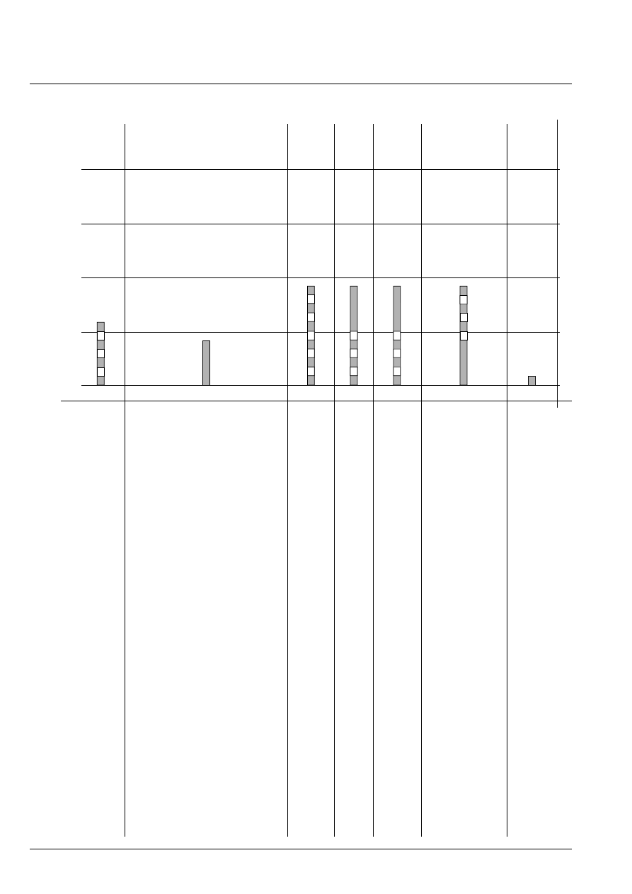
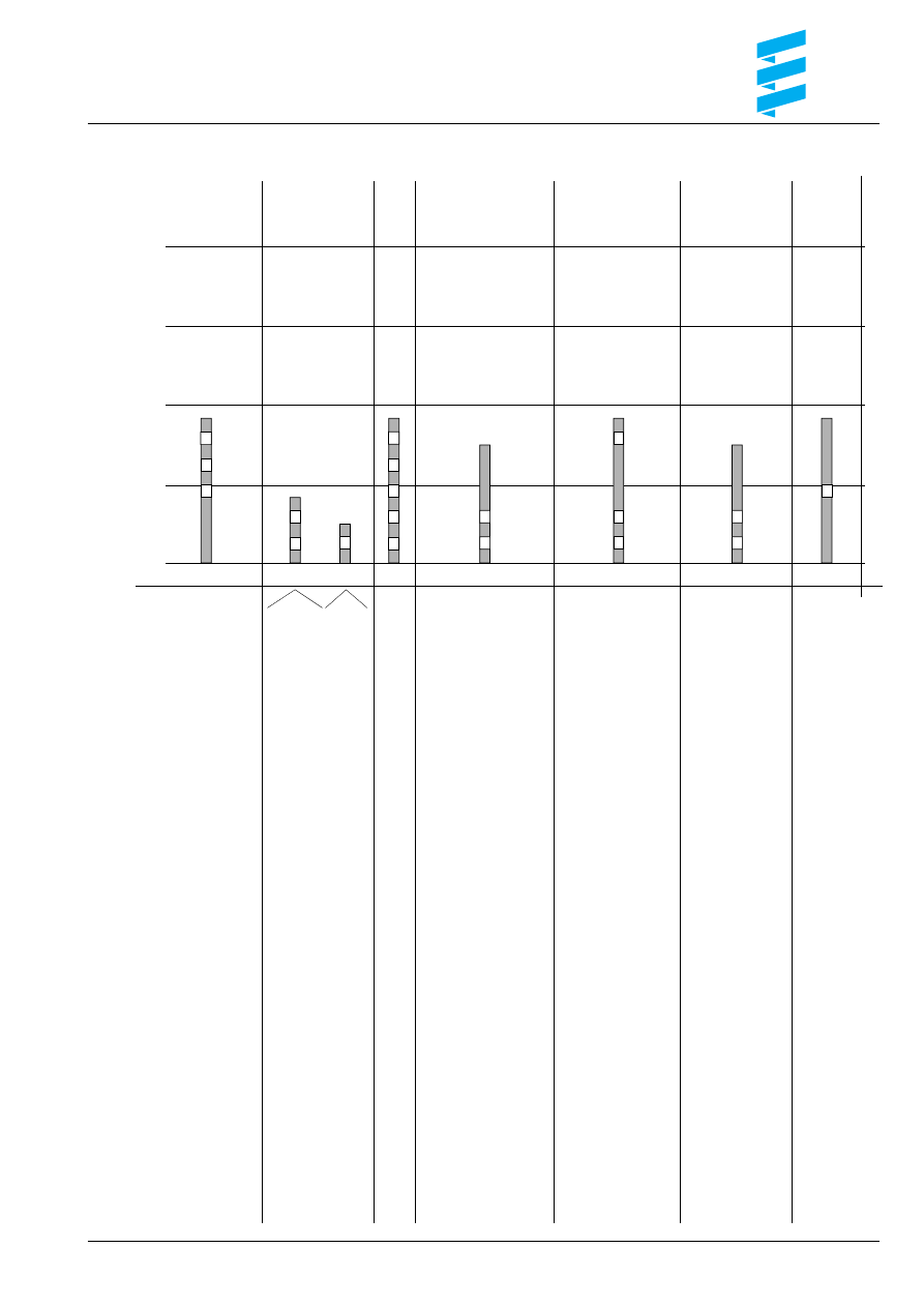
Control temperatures
VEHICLE BLOWER
ON
55
°
C
POWER
→
HIGH
72
°
C
HIGH
→
MEDIUM
78
°
C
MEDIUM
→
LOW
79
°
C
LOW
→
OFF
85
°
C
OFF
→
MEDIUM
68
°
C
MEDIUM
→
HIGH
68
°
C
LOW
→
MEDIUM
73
°
C
HIGH
→
POWER
60
°
C
Speed of
blower motor
POWER – 7300 rpm
HIGH
– 5700 rpm
MEDIUM – 3600 rpm
LOW
– 2000 rpm
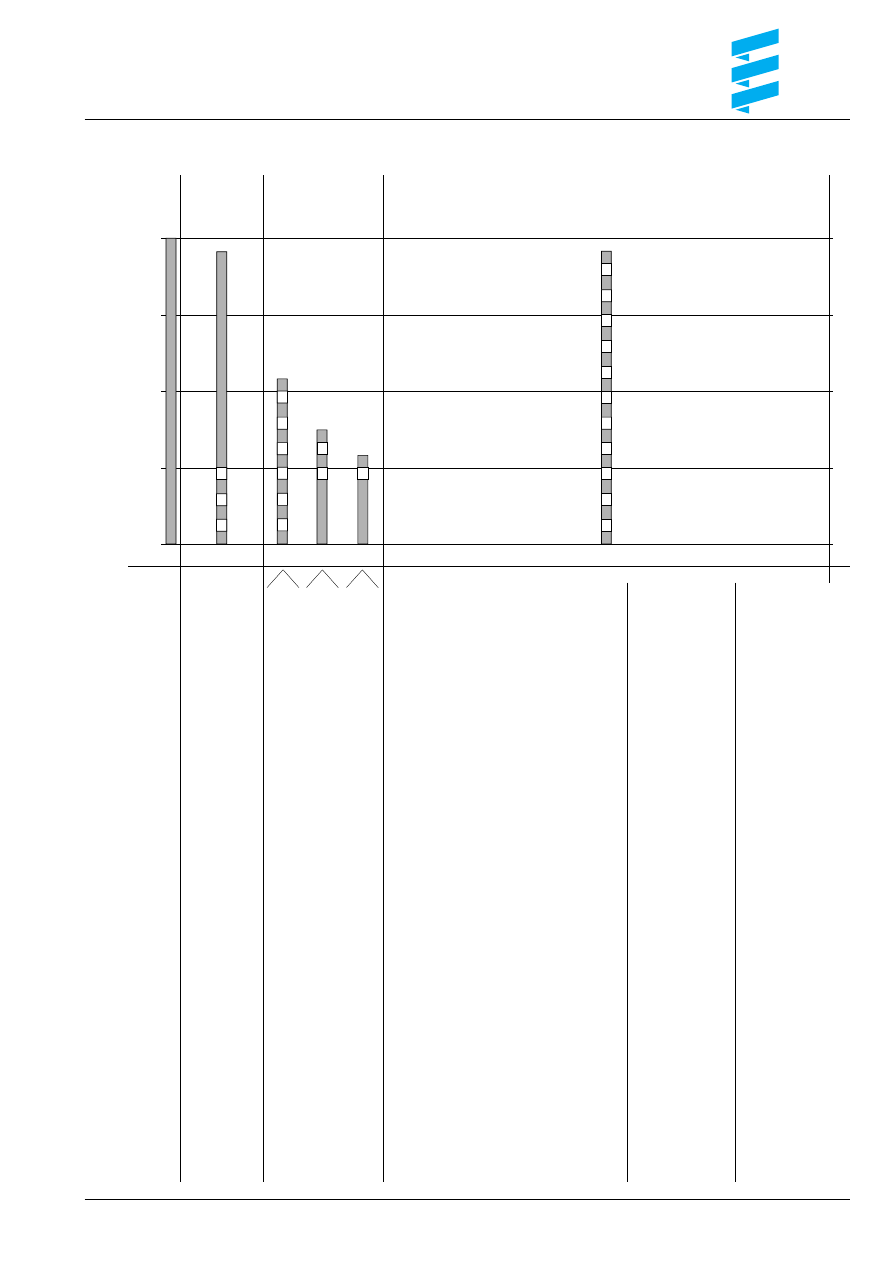
Time (s)
Speed of blower motor
(rpm)
Glow plug
Blower motor rpm
Frequency of
metering pump (Hz)
Startup sequence
0
1
2
3
4
5
6
7
8
0
100
150
200
250
300
350
400
450
50
8
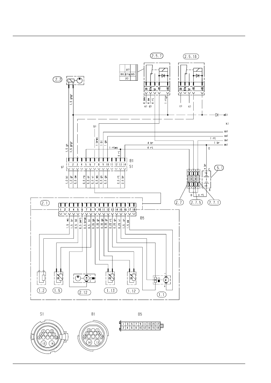
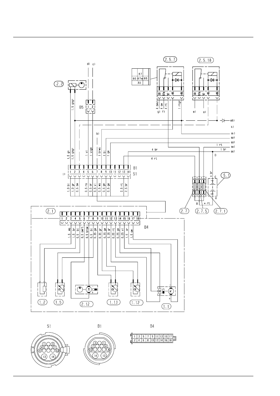
Wiring diagram: Heater, standard version – 25 2081 / 25 2044
9
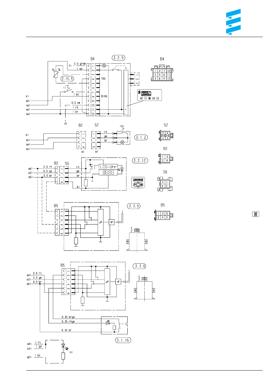
Wiring harness and operating elements, standard version – 25 2081 / 25 2044
Parts list
1.1
Burner motor
1.2
Glow plug
1.5
Safety thermal cutout switch
1.12
Flame sensor
1.13
Temperature sensor
2.1
Control unit
2.2
Fuel metering pump
2.5.7
Vehicle blower relay
2.5.18 Switch-over relay for water
circulation system, to be fitted
by customer if required
2.7
Main fuse
12 volt = 20 A
24 volt = 15 A
2.7.1
Fuse for control switch 5 A
2.7.5
Fuse for vehicle blower 25 A
2.12
Water pump
2.15.9 Sensor, external temperature
3.1.2
Heating switch (continuous operation)
3.1.16 Key button, radio remote control
3.2.9
Timer
3.2.12 Timer "Mini 98" version
3.3.6
Radio remote control
5.1
Battery
a)
Connection for operating device
b)
External control for water pump
(with plus signal)
c)
Water circulation changeover:
relay closes at a water temperature
of 68
°
C and opens at 63
°
C
d)
Ignition (terminal +15)
e)
Vehicle blower step switch
f)
Light (terminal 58)
g)
Connection for heater
h)
Display, flashing code (optional)
(LED at choice, series resistor 1.5 kohms)
i)
Connection for external heating key
k)
Connection leads in plug B2, B4 or B5
a2) Diagnosis
a3) Switch-on signal, S+
a4) Plus supply, +30
a5) Minus supply, –31
a6) Battery separating switch (+) on / off
(diode: order number 208 00 012)
*
Length A – B and C – D:
< 5 m: cross-section 4 mm
2
> 5 m < 8 m: cross-section 6 mm
2
Plug housing and socket housing are shown
from the conductor entry side
Cable colours
sw = black
ws = white
rt = red
ge = yellow
gn = green
vi = violet
br = brown
gr = grey
bl = blue
li
= lila
2044602B.
10
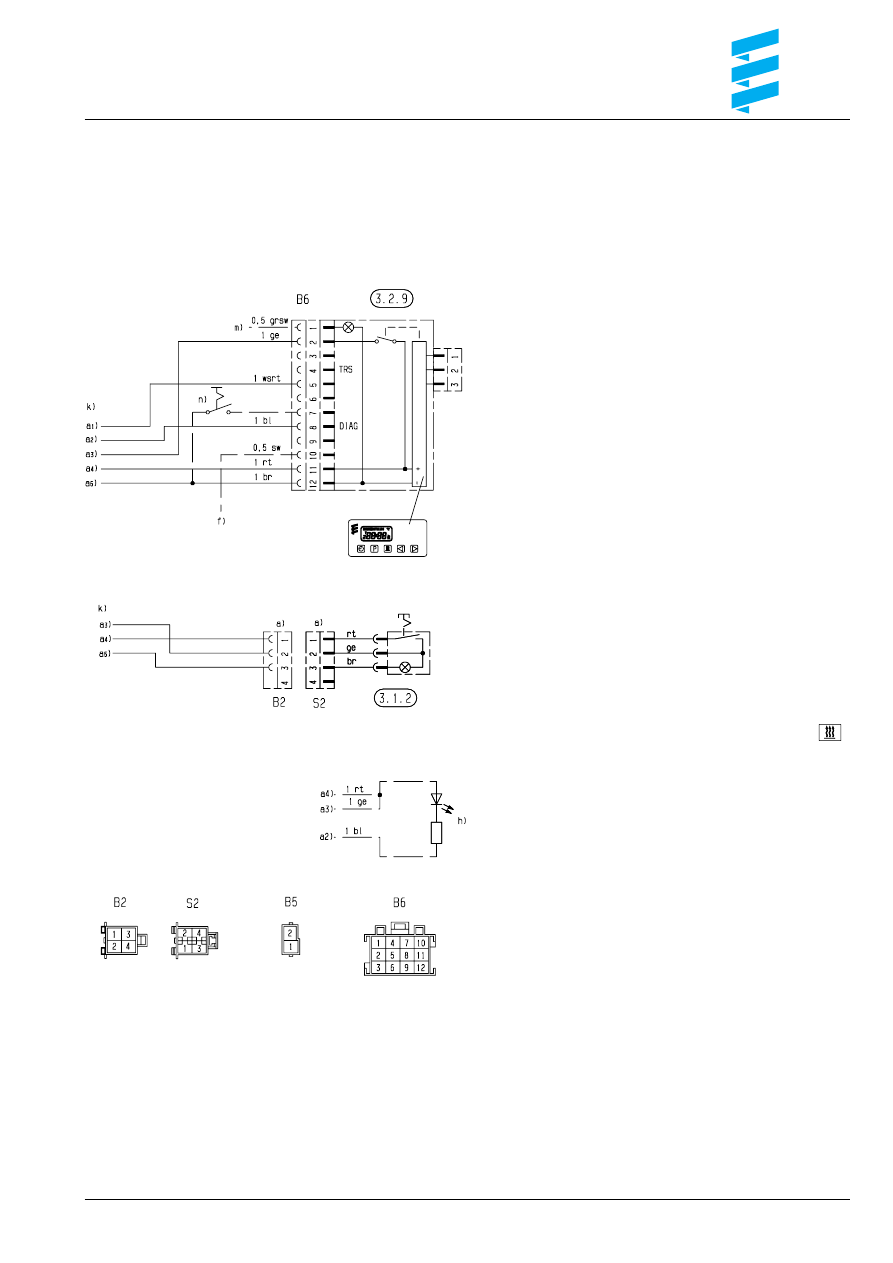
Wiring diagram: Heater, TRS 003 version – 25 2081 / 25 2044
11
Wiring harness and operating elements, TRS 003 version – 25 2081 / 25 2044
Parts list
1.1
Burner motor
1.2
Glow plug
1.5
Safety thermal cutout switch
1.12
Flame sensor
1.13
Temperature sensor
2.1
Control unit
2.2
Fuel metering pump
2.5.7
Vehicle blower relay
2.5.18 Switch-over relay for water
circulation system, to be fitted
by customer if required
2.7
Main fuse
12 volt = 20 A
24 volt = 15 A
2.7.1
Fuse for control switch 5 A
2.7.5
Fuse for vehicle blower 25 A
2.12
Water pump
(max. additional load: 4 A)
3.1.2
Heating switch (continuous operation)
3.2.9
Timer
5.1
Battery
a)
Connection for operating device
b)
External control for water pump
(with plus signal)
c)
with TRS D+ (alternator)
d)
with TRS HA– (auxiliary drive /
secondary drive) / minus switch
Connect lead to + pole if unavailable
e)
Water circulation changeover:
relay closes at a water temperature
of 68
°
C and opens at 63
°
C
(with D+ 58
°
C / 45
°
C)
f)
Ignition (terminal +15)
g)
Vehicle blower step switch
h)
Display, flashing code (optional)
(LED at choice, series resistor 1.5 kohms)
k)
Connection leads in plug B2 or B6
l)
Connection for heater
m) Light (terminal 58)
n)
Connection for external heating key
a1) TRS feedback
a2) Diagnosis
a3) Switch-on signal, S+
a4) Plus supply, +30
a5) Minus supply, –31
a6) Battery separating switch (+) on / off
(diode: order number 208 00 012)
*
Length A – B and C – D:
< 5 m: cross-section 4 mm
2
> 5 m < 8 m: cross-section 6 mm
2
Plug housing and socket housing are shown
from the conductor entry side
Cable colours
sw = black
ws = white
rt = red
ge = yellow
gn = green
vi = violet
br = brown
gr = grey
bl = blue
li
= lila
2044601B.
Repair steps
Remove / install
1. Control unit
2. Glow plug cable
3. Glow plug
4. Safety thermal cutout switch/temperature sensor/water
pump
5. Cover/blower
6. Flame sensor/heat exchanger fastening screws
7. Housing including heat exchanger, dismantled
8. Burner
9. Burner, dismantled
10. Heat exchanger
11. Heat exchanger, dismantled
12
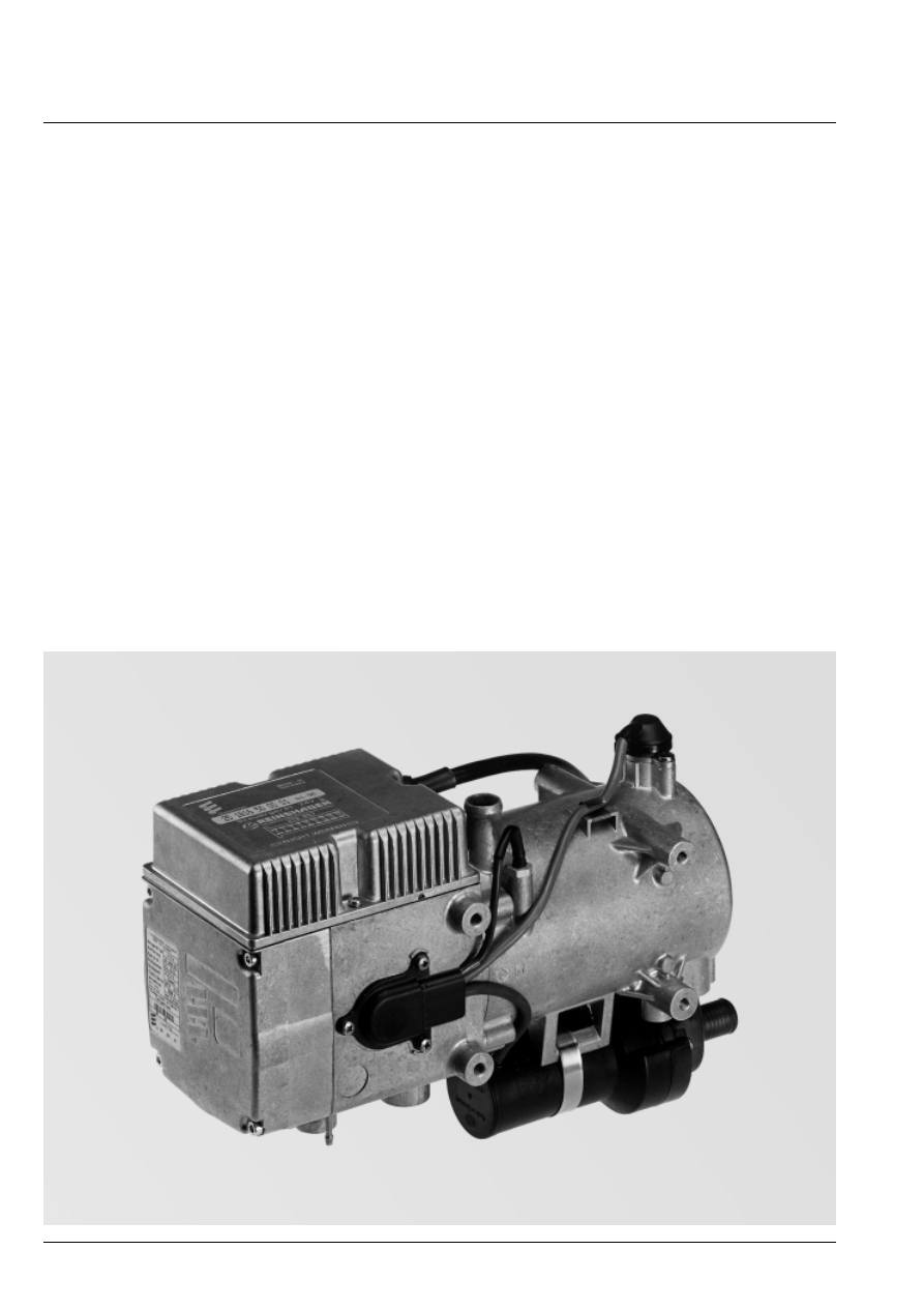
Overall view of heater
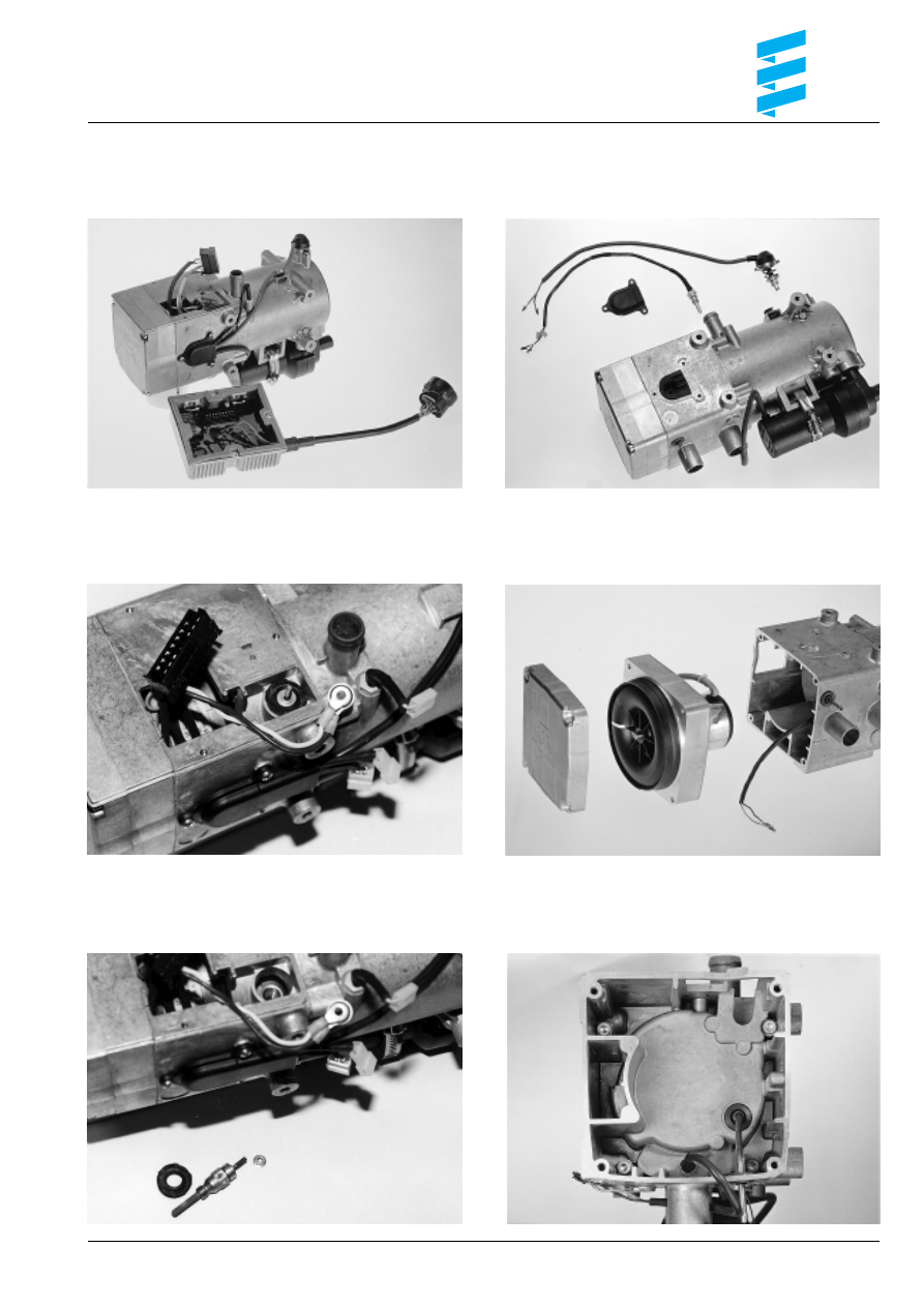
Remove / install
13
1. Control unit (on installation of the control unit,
grease the gasket with sealing paste)
4. Safety thermal cutout switch/temperature sensor/water
3. Glow plug
6. Flame sensor/heat exchanger fastening screws
5. Cover/blower (on installation of the cover,
clean the sealing surface and apply liquid seal)
2. Glow plug cable
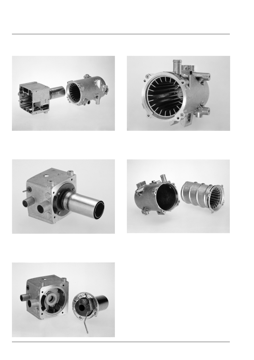
7. Housing including heat exchanger, dismantled
10. Heat exchanger
9. Burner, dismantled
8. Burner
11. Heat exchanger, dismantled
14
Wyszukiwarka
Podobne podstrony:
metr 10 instr
hydronic 10 model 2000
hydronic 10 technical
HYDRONIC 10 1
Hydronic 10 katalog
metr 10 instr
HYDRONIC 10 TRS 003 – 25 2081 25 2044
instr,10
10-oświetlenie elektryczne, Instrukcje BHP, XXXV - INSTR. ENERGETYCZNE
308, 309 instr 10[1] 2006
Ling COMBI instr 2009 10 26
celina instr, stos, podp, elektr, w imporcie weryf 10 01 2011 final
1116 instr 10[1] 2006
Szkol Instr ogólny 10 Badania lekarskie
Instrukcja 3 instr 10 12 J Kisilewicz K Puchala J Gladysz
więcej podobnych podstron