|
SKŁAD GRUPY:
|
|
|||
LABORATORIUM ELEKTROTECHNIKI |
|||||
Grupa laboratoryjna |
Ćw. 3 |
Temat: Pomiar mocy i energii w sieciach jednofazowych i trójfazowych |
Ocena:
|
||
Data wykonania:
|
|
|
|
||
Cel ćwiczenia :
Celem ćwiczenia jest poznanie metod pomiaru mocy czynnej i pozornej odbiorników symetrycznych i niesymetrycznych.
Wstęp teoretyczny :
Do pomiarów mocy służą przyrządy zwane watomierzami. Ustrój pomiarowy watomierza składa się z dwóch cewek: nieruchomej prądowej oraz ruchomej napięciowej. Watomierz przede wszystkim służy do pomiarów mocy czynnej. Gdy zastosuje się specjalny układ pomiarowy, w którym kąt między wektorami napięcia i prądu doprowadzonymi do przyrządu różni się o 90O od kąta mocy odbiornika, wówczas można watomierzem mierzyć moc bierną. Moc pozorną natomiast wyznacza się ze wskazań amperomierza i woltomierza.
Przebieg ćwiczenia :
Pomiar mocy i energii odbiornika jednofazowego :
Schemat połączeń :
I P A
R A W L
V U
R R R X X X
N
Tabela pomiarów :
L.p |
Załączone człony |
U |
I |
P |
S |
Q |
cos |
|
Ro |
Xo |
|
odbiornika |
V |
A |
W |
VA |
var |
- |
° |
|
|
1 |
3R=435 |
220 |
0,52 |
112 |
114,4 |
23,31 |
0,98 |
11,47 |
414,2 |
|
2 |
3X=210 |
220 |
0,97 |
12 |
213,4 |
213,06 |
0,05 |
87,13 |
|
226,4 |
3 |
3R i 3X |
220 |
1,01 |
120 |
222,2 |
187,01 |
0,54 |
57,31 |
|
|
L.p. |
czas 10 obrotów tarczy licznika |
CL |
PL |
P |
|
s |
obr/kWh |
W |
|
1 ( 3 R ) |
104,1 |
3000 |
115,27564 |
112 |
2 ( 3 X ) |
668 |
3000 |
17,964 |
12 |
3 (3R 3X ) |
95,7 |
3000 |
125,391 |
120 |
Wzory i przykładowe obliczenia :
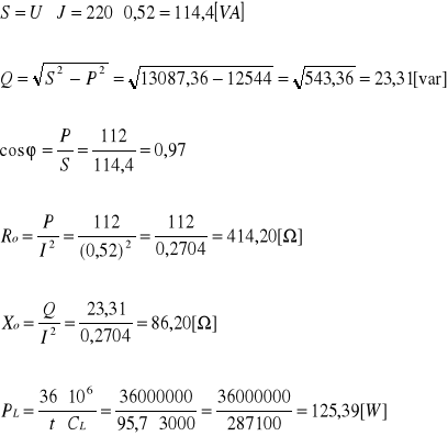
PL - moc czynna wynikająca ze wskazań licznika
t - czas 10 obrotów tarczy licznika
CL - stała licznika [ obr/kWh ]
Spis przyrządów :
Watomierz zakres - 2,5
Woltomierz zakres - 300
Amperomierz zakres - 0,5
Licznik - stała licznika 3 tys.obr /kWh
Pomiar mocy czynnej odbiornika połączonego w trójkąt :
schemat połączeń :
IR P1
R
IS
S
IT
T
Tabela wyników
|
Załączone człony |
|
|
|
|
|
|
|
|
|
L.p. |
odbiornika w fazie |
IR |
Is |
IT |
URS |
UST |
URT |
P1 |
P2 |
P |
|
R S T |
|
A |
|
|
V |
|
|
W |
|
1 |
2R 2R 2R |
1 |
1 |
1 |
380 |
380 |
380 |
328 |
330 |
658 |
2 |
1X 3R 2R |
1,26 |
0,78 |
1,28 |
380 |
380 |
380 |
480 |
200 |
680 |
3 |
1RX 1RX 2RX |
0,9 |
0,9 |
1,42 |
380 |
380 |
380 |
590 |
-170 |
420 |
Wzory i przykładowe obliczenia :
![]()
Spis przyrządów :
2 watomierze zakres - 2,5
Woltomierz zakres - 300
3 amperomierze zakres - 0,5
Wnioski :
W sieciach jednofazowych na podstawie pomiarów mocy odbiornika mamy różnicę między rezystancją a reaktancją. W przypadku rezystancji różnica ta spowodowana jest stanami mocy w woltomierzu i cewce napięciowej woltomierza. Natomiast w przypadku reaktancji od pomiaru mocy odczytanych na watomierzu odejmuje się moce, które się generują w cewce prądowej amperomierza i watomierza. W układzie gdzie wykorzystany był watomierz i licznik w wynikły rozbieżności we wskazaniach mocy na obydwu tych przyrządach. Różnice te spowodowane były jakością wykonania licznika. Pomiar mocy w układzie trójfazowym trójprzewodowym gdzie odbiornik połączony był w trójkąt zaobserwowaliśmy z jakiego typu odbiornikiem mamy do czynienia : symetrycznym czy niesymetrycznym. O symetrii połączenia odbiornika świadczą równe odczyty na obu watomierzach. W przypadku niesymetrii odczyty te różnią się, co wskazuje że mamy do czynienia z odbiornikiem o charakterze indukcyjnym.
Instytut Elektroenergetyki
Wydział Górniczy

A
![]()
Wyszukiwarka
Podobne podstrony:
jurdziak, W6 - górnictwa
woźniak, W6 - górnictwa
2998, W6 - górnictwa
madziarz, W6 - górnictwa
przylibski, W6 - górnictwa
jurdziak, W6 - górnictwa
drzymała, W6 - górnictwa
wojtaszek, W6 - górnictwa
przylibski, W6 - górnictwa
wojtkiewicz, W6 - górnictwa
przylibski, W6 - górnictwa
madziarz, W6 - górnictwa
hawrysz, W6 - górnictwa
cygan, W6 - górnictwa
więcej podobnych podstron