38

19.6 Loosen cable retaining clamp to set choke cabie freeplay 19.8 Vacuum take off point - 1000 models

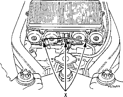
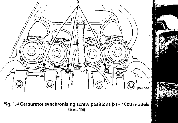
Fig. 1.3 Carburetor synchronising screw positions (x) - 600 models (Sec 19)
20.2 Rem<

20.3 Ensu
carburetoi settle the necessary 12 Whe engine, dis Refit all th of the seal necessary
carburetors and examination of the choke plungers as described in Chapter 4.
6 Once the choke mechanism is operating smoothly it is necessary to ensure that there is a smali amount of freeplay on the choke cable. it is recommended that there should be approximately 2-3 mm (0.08 -0.12 in) of lever travel, measured at the base of the leyer, before the mechanism starts to move. To adjust the cable, slacken the choke cable clamping screw, situated on the carburetors, then move the lower end of the cable until the required amount of freeplay is obtained. Tighten the clamping screw securely.
7 Once the throttle and choke mechanisms are known to be operating correctly the carburetors should be synchronized as follows.
Synchronization
Ref er to photo 19.8 and Figs. 1.3, 1.4
Notę: A set of accurate vacuum gauges is essential for synchronizing the carburetors; if not avai1able, the job should.be entrusted to a Honda Service Agent. On no account attempt to adjust synchronization by feei -it will almost certainly make things worse.
Notę: The carburetors must be synchronized with the engine at its normal operating temperaturę and the machinę on its center stand.
8 On 600 models, remove the fuel tank, as described in Chapter 4, and the left and right side fairings. Slacken and remove the four screws, one in each inlet tract, from the cylinder head and screw in the adaptors. Connect the vacuum gauge hoses to the relevant adaptors and arrange a temporary fuel supply, either by using a smali temporary tank or by using extra long fuel pipes to the now remote fuel tank on a nearby bench. On 1000 models raise the fuel tank up and support it on its prop stay. Remove the rubber pług or vacuum tubę (as applicable) from the vacuum take-off point on the top of each carburetor and connect the vacuum gauge hoses to the take-off points.
9 Start the engine and allow it to warm up to normal operating temperaturę. If the gauges are fitted with damping adjustment, set this so that the needle flutter is just eliminated but so that they can still respond to smali changes in pressure. Set the engine to the specified idle speed.
10 With the engine idling, check that all needles produce the same reading. A tolerance of 2 cm Hg on 1000 models and 4 cm Hg on 600 models is permissible but it is better to have all cylinders adjusted to the same reading; this is by no means as difficult as it would appeaf, requiring only a little care and patience. Notę that it does not matte what the reading is, only that it is the same for all four cylinders. Stop th< engine and allow it to cool down if it overheats.
11 The carburetors are adjusted by the three screws situated inbetween each carburetor, in the throttle linkage. Number two cylindef should be used as the base setting and the other three cylinders should be adjusted to the same. Notę: Do not press down on the screws whilst adjusting them, otherwise a faise reading wili be obtained. When all the-
20 Fueł)
Ref er top! Wamiitg; the form a throughĘ before t
1 The| checkedf
2 The f and its I
3 On(
Wyszukiwarka
Podobne podstrony:
immediately blocked up and protected by means of 130 retaining walls of dry masonry and 79 carth tcr
SCAN0048 CHAPTER 4 T Retina 77 Perifoveal area FIGURĘ 4-19 Regions of retina and corresponding histo
lastscan234 CHAPTER 1 TEMPOROMANDiBULAR JCNNT AND THE CERV!CAL S- V ■ 27 FIGURĘ 1-38 ■ Muscłes of fa
attachment (19) )YI-Daily CBOT HERE YOU GO OUIHN I LOKK AT AS MANY AS ! CAN. SOME LINĘ UP AND SOME D
Suzuki RM2507 PERIODIC MAINTENANCE 2-21REAR SUSPENSION ♦ Move the rear suspension
00104 U22672e84810718d615778de2b5b475 103 The OCAP benefits are experienced by production superviso
grooves of the record? Has the problem appeared suddenly or has it been building up and growing wors
Chapter 12Occupational Injuries and InfectionsINJURIES It is understandable that in a sphere where f
S20C 409120813261 kuffle Using color B and wilh Ił e riyhl side fscing, pick up and knit 1 stitcn in
Theoretical and Methodological Problems 19 The ES area is an attractive research and application fie
więcej podobnych podstron