3582278007
Electronic Lab Manuał
Figurę. The NAND gate.
Enter the output values into a truth table as show below. Vary the inputs and record the output of the gate F and the actual voltage V. E\amine the output of the NAND gate when one of the inputs is left floating (not connected). How can a NAND gate be used as an inverter?
|
A |
B |
F |
|
0 |
0 | |
|
0 |
1 | |
|
1 |
0 | |
|
1 |
1 |
Section 4. The implementationof the NOR gate.

Enter the output values into a truth table for different values for A & B as show below. Vary the inputs and record the output of the gate F. were F is given byF=(A + B)’
|
A |
B |
F |
|
0 |
0 | |
|
0 |
1 | |
|
1 |
0 | |
|
1 |
1 |
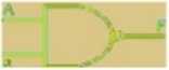
Section 5: Implementation of X-OR Gate:
A
B
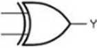
Enter the output values into a truth table for different values for A & B as show below. Vary the inputs and record the output of the gate F. were F is given byF=(A + B)’
|
A |
B |
F |
|
0 |
0 | |
|
0 |
1 | |
|
1 |
0 | |
|
1 |
1 |
K. Adite^has 6
Wyszukiwarka
Podobne podstrony:
Electronic Lab Manuał Laboratory 4. The Fuli Adder ComponenŁs: IC 7486. IC 7408. IC 7432 Theory:FULL
Electronic Lab Manuał The Laboratory: Section 1. NOT Gate Implementation 7402(NOR) E Vcc 4B 4A 4Y 3B
Electronic Lab ManuałBCA I SEMESTERSubject Codę: BCA-104P ELECTRONICS LABORATORY MANUAŁ Digital circ
Electronic Lab Manuał OPERATING MODĘ Asyn. Set Asyn. Reset (Clear) Undetermined (a) Load
Electronic Lab ManuałLaboratory Exerci.se 10 -13 : Shift Registers Shift registers are a type of seq
POWER ELECTRONICS LAB. EED 4. Draw the equivalent Circuit of IGBT. 5. What arc on
POWER ELECTRONICS LAB. EED 8) Connect a voltmeter across the gate -emitter and another voltmeter acr
EEE.MRCEW E&E LAB MANUAŁ1. BASIC ELECTRONIC COMPONENTS 1.1. COLOUR CODING OF RESISTOR Colour Cod
AEC LAB MANUAŁHARTLEY OSCILLATOR AIM: Testing for the performance of BJT Haiiley oscillator for
CeII Transport Lab Series GLUE IN THE FOLLOWING PROCEDURES AND CREATE DATA TABLES IN YOUR LAB MANUAŁ
POWER ELECTRONICS LAB. EED Transfer Characteristics: 15) Keep the V o: constant us
POWER ELECTRONICS LAB. EED Circuit Diagram : s Procedurę: 1. Connect the input sup
Celi Membranes: Intracellular pH and Electrochemical Potential Membranę Figurę 1 Principles of the
f2 5 FIGURĘ 2.5 The java to o ket
FIG 01(1) Figuro 1. The pin ttirnMer Jocie, culawaj- view. Figurę 2, The pin lumbler lock, fronl vie
więcej podobnych podstron