1310109077
54 S. Frąckowiak

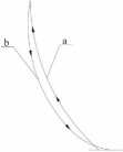
Rys. 7. Rodzaje ruchów rolki: a - ruch w kierunku do krawędzi zewnętrznej krążka, b - ruch w kierunku środka krążka Fig. 7. Kinds ofroller motions: a - motion towards the disk out er edge, b - motion towards the disk middle
6.2. Badanie ruchów narzędzia w procesie
wyoblania
W Instytucie Obróbki Plastycznej został wykorzystany program CAM w procesie wspomagania projektowania trajektorii narzędzia o nazwie Trop CNC. Jego głównym zadaniem jest przekonwertowanie rysunku typu AutoCAD na kod CNC oraz wyszukanie błędów i graficzna prezentacja poszczególnych ruchów narzędzi. Zastosowanie takiego programu znacznie przyspiesza pisanie programu sterującego oraz ułatwia wprowadzanie zmian celem optymalizacji procesu. Na rys. 8 przedstawiono przykładową trajektorię rolki wyobla-jącej składającą się z 124 ruchów, w procesie wyoblania osłony wywietrznika KHDA-36 [1].
6.2. Examination of tool motions in the pro-
cess of spinning
In the Metal Forming Institute, a CAM program has been used in the process of aiding the design of tool trajectory called Trop CNC. Its essential task is to convert an AutoCAD type drawing into a CNC codę and to find mistakes and graphically present the individual tool motions. Application of such a program sig-nificantly accelerates writing of the controlling program and facilitates modifications in order to optimize the process. Fig. 8 shows an exam-ple of a spinning roller trajectory consisting of 124 motions in the process of spinning a KHDA-36 ventilator casing [1 ].

Rys. 8. Trajektoria ruchów rolki w procesie wyoblania osłony wywietrznika KHDA-36 [1]
Fig. 8. The trajectory of roller motions in the process of spinning a KHDA-36 ventilator casing [1]
Wyszukiwarka
Podobne podstrony:
81676 Str089 (4) 89 t i Rys. 7.3.2. Rodzaje ślimaków w zależności od kierunku nacinania linii zwoju:
IMG00089 89 Rys. 7.3.2. Rodzaje ślimaków w zależności od kierunku nacinania linii zwoju: a) ślimak p
Rys. O 33. Jaki powinien być kierunek (do lub od węzła) i wartość strumieiua objętości prądu powietr
img184 (12) m. in. ruchów gałki ocznej. W toku czytania oko wl konuje trzy rodzaje ruchów: ruch post
iJLl Rys. 5. Rodzaje gwintów ze względu na kierunek zwojów: a) gwint lewy; b) gwint prawy Rys. 6. Kr
70516 IMGh85 (3) 62 Rozdział 2 Rys. 4. Struktura mapowa rodzajów uczenia się (—> jeden kierunek d
Projektowanie procesów technologicznych wytloczek ... 53 Rys. 5. Rodzaje trajektorii ruchów narzędzi
geologia matpom01 I tv» - “ “ r * Ryc. 13.1. Główne rodzaje
zadanych Rys. 8. Otrzymana charakterystyka wskazań magnetometru w kierunku osi X i Y Rys. 6. Schemat
więcej podobnych podstron