
FUNDAMENTALS OF DOSIMETRY BASED ON ABSORBED-DOSE
STANDARDS
D.W.O. Rogers
National Research Council of Canada
e-mail: drogers@physics.carleton.ca (from 2003)
WWW: http://www.physics.carleton.ca/∼drogers
This chapter is the basis of a lecture given at the AAPM’s 1996 Summer School in Vancouver, BC. It has
been published by the AAPM in “Teletherapy Physics, Present and Future” edited by J. R. Palta and T. R.
Mackie, pages 319 – 356 (AAPM, Washington DC, 1996).
David Rogers is now at the Physics Department of Carleton University, Ottawa, K1S 5B6.
ABSTRACT
This chapter reviews the fundamentals of radiation dosimetry needed to do reference dosimetry for external
beam radiotherapy when starting from an ion chamber calibrated in terms of absorbed-dose to water. It
briefly reviews the status of primary standards for absorbed dose to water. The k
Q
formalism developed to
utilize these absorbed-dose calibration factors is described for use in electron and photon beams. In the ideal
case, the needed k
Q
factors are measured for each ion chamber and beam quality of interest in the clinic.
Equations are developed for the factors needed to utilize this formalism in the proposed TG–51 dosimetry
protocol of the AAPM. Special attention is paid to the issue of specifying beam quality in terms of percentage
depth-dose at 10 cm for photon beams and R
50
for electron beams. A proposal for using a reference depth of
0.6 R
50
− 0.1 cm in electron beam dosimetry is discussed. Factors needed for using plane-parallel chambers
in a water phantom are also reviewed.
Contents
1. INTRODUCTION
3
2. STATUS OF ABSORBED-DOSE STANDARDS
3
3. FORMALISM USING ABSORBED-DOSE CALIBRATION FACTORS
4
4. ION CHAMBERS
5
4.A. Theory . . . . . . . . . . . . . . . . . . . . . . . . . . . . . . . . . . . . . . . . . . . . . . . . .
5
4.A.1) Spencer-Attix Cavity Theory . . . . . . . . . . . . . . . . . . . . . . . . . . . . . . . .
5
4.A.2) Handling Humidity Variation . . . . . . . . . . . . . . . . . . . . . . . . . . . . . . . .
5
4.A.3) Cavity Theory with Corrections . . . . . . . . . . . . . . . . . . . . . . . . . . . . . . .
6
4.A.4) The Wall Correction Factor, P
wall
. . . . . . . . . . . . . . . . . . . . . . . . . . . . .
6
4.A.5) The Replacement Correction Factor, P
repl
= P
gr
P
fl
. . . . . . . . . . . . . . . . . . . . .
7
4.A.6) The Central Electrode Correction Factor, P
cel
. . . . . . . . . . . . . . . . . . . . . . .
9
4.B. Practical Considerations . . . . . . . . . . . . . . . . . . . . . . . . . . . . . . . . . . . . . . .
10
4.B.1) Correction for Ion Recombination, P
ion
. . . . . . . . . . . . . . . . . . . . . . . . . .
10
4.B.2) Temperature and Pressure Corrections . . . . . . . . . . . . . . . . . . . . . . . . . . .
10
4.B.3) Waterproofing Sleeves . . . . . . . . . . . . . . . . . . . . . . . . . . . . . . . . . . . .
10
5. BEAM-QUALITY SPECIFICATION
11
5.A. Why Do We Need to Specify Beam Quality? . . . . . . . . . . . . . . . . . . . . . . . . . . . .
11
5.B. Specification of Photon Beam Quality . . . . . . . . . . . . . . . . . . . . . . . . . . . . . . .
11
5.C. Specification of Electron Beam Quality . . . . . . . . . . . . . . . . . . . . . . . . . . . . . . .
13
5.C.1) Determination of R
50
. . . . . . . . . . . . . . . . . . . . . . . . . . . . . . . . . . . .
13
5.C.2) The mean energy at the phantom surface, E
o
. . . . . . . . . . . . . . . . . . . . . . .
14
5.C.3) Problems with stopping-power ratios using mono-energetic beams . . . . . . . . . . . .
15
5.C.4) Direct use of R
50
as beam quality specifier . . . . . . . . . . . . . . . . . . . . . . . .
15
6. VALUES OF k
Q
16
6.A. Calculation of k
Q
Values . . . . . . . . . . . . . . . . . . . . . . . . . . . . . . . . . . . . . . .
16
6.A.1) An equation for k
Q
. . . . . . . . . . . . . . . . . . . . . . . . . . . . . . . . . . . . . .
16
6.A.2) Photon Beams . . . . . . . . . . . . . . . . . . . . . . . . . . . . . . . . . . . . . . . .
16
6.A.3) Electron Beams . . . . . . . . . . . . . . . . . . . . . . . . . . . . . . . . . . . . . . . .
19
6.B. Measurement of k
Q
Values . . . . . . . . . . . . . . . . . . . . . . . . . . . . . . . . . . . . . .
22
7. SUMMARY
23
8. ACKNOWLEDGMENTS
23
9. REFERENCES
23

Dosimetry Fundamentals: 1996 AAPM Summer School
page 3
1.
INTRODUCTION
Accurate measurement of the dose delivered to the tumor in external beam radiotherapy is one of the
primary responsibilities of a medical physicist. In general, such measurements have been based on the use
of ion chambers calibrated in terms of exposure or air kerma and the application of a dosimetry protocol
such as the AAPM’s TG–21 protocol (AAPM TG–21 1983; AAPM TG–21 1984; Schulz et al 1986) or the
IAEA’s Code of Practice (IAEA 1987). These protocols were a significant step forward since they provided a
procedure which was capable of incorporating the correct physics. This came at the expense of considerable
complexity. One manifestation of this complexity is a large number of small errors and inconsistencies in
the TG–21 protocol which fortunately tend to cancel out (see e.g. my lecture at the previous summer school
which dealt with many of these issues and gave a corrected derivation of the TG–21 protocol equations
(Rogers 1992d)). However, even using the corrected protocols the overall uncertainty in the absorbed dose
assigned under reference conditions is about 3 to 4% (all uncertainty estimates in this chapter are for one
standard deviation, representing a confidence level of 68%). For extensive reviews of various dosimetry
protocols see Nath and Huq (1995) and Andreo (1993).
Much of the complexity of the TG–21 and similar protocols comes from the fact that they start from an
ion chamber calibrated free-in-air for one quantity, air kerma, and must transfer this information to obtain
another quantity, absorbed dose to water, based on a measurement in a phantom. To overcome these
complexities, primary standards laboratories have been developing standards for absorbed dose to water in
photon beams from
60
Co and accelerator beams (Rogers 1992b; Shortt et al 1993; Domen 1994; Boutillon
et al 1994; Ross and Klassen 1996) and these have an uncertainty of 1% or less. Also, many improvements
in radiation dosimetry have been made in the 15 years since TG–21 was developed. To make use of this
greater accuracy and to incorporate these improvements, the AAPM has established a task group, TG-51,
to develop a new external beam dosimetry protocol. There are several approaches which could be used, but
after careful study it has been decided to base the new protocol on calibrating ion chambers in terms of
absorbed dose to water in a
60
Co beam.
In this chapter I will discuss the fundamentals of ion chamber dosimetry which underlie the approach being
adopted by TG-51, with emphasis on various developments which have occurred in the last few years.
However, this is a personal contribution and although I am on TG-51, this document does not represent the
opinion of TG-51, nor does it present many of the details of the protocol since these are still evolving.
2.
STATUS OF ABSORBED-DOSE STANDARDS
Three very different approaches have been used to provide standards for absorbed dose to water in photon
beams. I reviewed these at the previous summer school (Rogers 1992b) and progress has continued since
then. The most common approach is to use a graphite calorimeter to establish the absorbed dose to graphite
and then use various procedures to infer the absorbed dose to water in the same beam (Pruitt et al 1981;
Domen and Lamperti 1974). A second approach is to use the total absorption in Fricke solution of an
electron beam of known energy and charge to calibrate the solution and then use the Fricke in a small vial
to establish the dose at a point in a water phantom by assuming that the calibration of the Fricke solution
(i.e. ²G) does not change with beam quality (Feist 1982). A third approach is to use water calorimetry,
either to calibrate Fricke solution in the beam quality of interest (Ross et al 1984; Ross et al 1989) or use a
small volume of sealed, high-purity water in a water phantom to do a direct measurement of the absorbed
dose to water (Domen 1994; Seuntjens et al 1993). There has been a recent review of both forms of water
calorimetry by Ross and Klassen (1996).
There have been several comparisons of the standards in different national standards laboratories and there
is satisfactory agreement between the various methods at the 1% level or better (Boutillon et al 1994; Shortt
et al 1993). An important point is that each of these three methods has different types of systematic uncer-
tainties and thus the system of standards being developed is highly robust against systematic errors affecting
all the standards. The situation for air-kerma standards is different since almost all the primary standards
2. STATUS OF ABSORBED-DOSE STANDARDS

page 4
D.W.O. Rogers
in the world use the same basic approach (a graphite-walled cavity ion chamber) and thus comparisons be-
tween them cannot resolve systematic uncertainties in the technique itself. More specifically, there have been
challenges to parts of the theory underlying the air-kerma standards and different approaches in establishing
certain corrections lead to up to 1% differences in these standards, in particular between the Canadian and
US standards (Bielajew and Rogers 1992).
In summary, there is a robust system of absorbed dose to water standards in place in primary standards
laboratories. These standards are capable of measuring the absorbed dose not only in
60
Co beams but in
accelerator beams.
3.
FORMALISM USING ABSORBED-DOSE CALIBRATION
FACTORS
Given the existence of the high quality primary standards for absorbed dose to water and the fact that the
absorbed dose to water is the quantity which is used for reference dosimetry in radiotherapy, it makes sense
to base clinical dosimetry on absorbed-dose calibration factors for ion chambers. Ion chambers are used
because high-quality chambers are available for reasonable cost, they have the capability of making precise
and stable measurements in radiation fields encountered in the clinic, and the theory for interpreting their
output is reasonably well understood. In the last few years a formalism for such a process has been widely
discussed (Hohlfeld 1988; ICRU 1990; Rogers 1992c; Andreo 1992; Rogers et al 1994) and has been adopted
for TG–51.
One starts with an absorbed-dose to water calibration factor, N
Q
D,w
, defined by:
D
Q
w
= M P
ion
N
Q
D,w
[Gy]
(1)
where D
Q
w
is the absorbed-dose to water (in Gy) at the point of measurement of the ion chamber in the
absence of the chamber (the center of a cylindrical chamber and the front of the air cavity in a plane-
parallel ion chamber), M is the temperature and pressure corrected (see section 4.B.2) electrometer reading
in coulombs (C) or meter units (rdg), P
ion
corrects for ion chamber collection efficiency not being 100% (see
section 4.B.1), and N
Q
D,w
is the absorbed-dose to water calibration factor (in Gy/C or Gy/rdg) for the ion
chamber when placed under reference conditions in a beam of quality Q. In North America the calibration
factor applies under reference conditions of temperature, pressure and humidity, viz. 22
◦
C, 101.3 kPa and
relative humidity between 20 and 80%. Note that because it can become significant in accelerator beams,
the inclusion of P
ion
in eq.(1) is different from previous North American practice for air-kerma or exposure
calibration factors where ion recombination effects were part of the calibration factor, i.e. the exposure, X,
is given by: X = M N
X
where N
X
is the exposure calibration factor.
Clearly the most direct method of clinical dosimetry is to get an ion chamber calibrated for each beam
quality Q needed for a clinic and then apply eq.(1). Since this would both be very expensive (it requires
an accelerator for the calibration) and available at very few places (the ADCL’s do not have accelerators of
their own), it is easier to start from an absorbed-dose calibration factor for a
60
Co beam, viz. N
60
Co
D,w
. In this
case, define a factor k
Q
such that:
N
Q
D,w
= k
Q
N
60
Co
D,w
,
[Gy]
(2)
i.e. k
Q
converts the absorbed-dose calibration factor for a
60
Co beam into a calibration factor for an arbitrary
beam quality Q. In general, the value of k
Q
is chamber specific. Using k
Q
, gives:
D
Q
w
= M P
ion
k
Q
N
60
Co
D,w
[Gy].
(3)
In an ideal world, values of k
Q
measured using primary standards for absorbed dose would be available for
all the ion chambers used for reference dosimetry. Such a project is underway at NRCC for accelerator
photon beams for many widely used Farmer-like ion chambers, but equivalent data will not be available
3. FORMALISM USING ABSORBED-DOSE CALIBRATION FACTORS
Dosimetry Fundamentals: 1996 AAPM Summer School
page 5
for all chambers, nor for electron beams in the foreseeable future. Thus it is important to have ways of
calculating k
Q
, and this is discussed below after a review of the necessary fundamentals.
4.
ION CHAMBERS
4.A.
Theory
4.A.1)
Spencer-Attix Cavity Theory
The central theory underlying ion chamber dosimetry is Spencer-Attix cavity theory(1955) which relates the
dose delivered to the gas in the ion chamber, D
gas
, to the dose in the surrounding medium, D
med
by the
relationship:
D
med
= D
gas
µ
L
ρ
med
gas
,
(4)
where the stopping-power ratio,
³
L
ρ
´
med
gas
, is the ratio of the spectrum averaged mass collision stopping powers
for the medium to that for the gas where the averaging extends from a minimum energy ∆ to the maximum
electron energy in the spectrum. The fundamental assumptions of this theory are that: i) the cavity does
not change the electron spectrum in the medium; ii) all the dose in the cavity comes from electrons entering
the cavity, i.e.
they are not created in the cavity; and iii) electrons below the energy ∆ are in charged
particle equilibrium. Unlike Bragg-Gray cavity theory, Spencer-Attix theory applies where charged particle
equilibrium of the knock-on electrons above ∆ does not exist, which is generally the case near an interface
between media or at the edge of a beam.
There is an extensive literature on the Monte Carlo calculation of stopping-power ratios (Nahum 1978;
Andreo and Brahme 1986; ICRU 1984a; Ding et al 1995) and there is agreement between various calculations
at about the 0.1% level if the same stopping power data are used. However, there has been considerable
confusion caused by the use of a variety of different electron stopping power-data sets in earlier protocols
(see, e.g. Rogers et al (1986)). There is now a consensus to use the stopping-power data from ICRU Report
37 (1984b) (based on the work of Berger and Seltzer at NIST(1983)) and they are used exclusively here.
The TG–21 protocol used these data for electron beams but used an earlier set (which differed by over 1%
in places) for the photon beam data.
4.A.2)
Handling Humidity Variation
To make use of eq.(4) requires a connection between D
gas
and the charge measured from the ion chamber.
If M
0
is the charge released in the ion chamber, then:
D
gas
=
µ
W
e
gas
M
0
m
gas
(Gy),
(5)
where
¡
W
e
¢
gas
gives the energy deposited in a gas per unit charge released, and fortunately for ion chamber
dosimetry, is a constant for dry air, independent of electron energy (viz. 33.97±0.05 JC
−1
Boutillon and
Perroche-Roux (1987)), and m
gas
is the mass of the gas in the cavity. One complication in ion chamber
dosimetry is that the humidity in the air causes each of the quantities
¡
W
e
¢
gas
, m
gas
and
¡
L/ρ
¢
w
gas
to vary by
anywhere up to 1%. This has caused considerable unnecessary confusion in the TG–21 protocol (see Rogers
and Ross (1988) and Mijnheer and Williams (1985) and references therein for a complete discussion). To
handle these variations, one defines a humidity correction factor:
K
h
=
µ
W
e
gas
air
m
air
m
gas
µ
L
ρ
air
gas
,
(6)
4. ION CHAMBERS
page 6
D.W.O. Rogers
which has the feature of being equal to 0.997 for relative humidity between roughly 15% and 80%. Multiplying
the right side of eq.(5) by K
h
and inserting the results into eq.(4) leads to the following simplifications:
D
med
= D
air
µ
L
ρ
med
air
(Gy),
(7)
D
air
= K
h
µ
W
e
air
M
0
m
air
(Gy)
(8)
where eq.(7) has made use of the fact that
¡
L/ρ
¢
med
gas
¡
L/ρ
¢
gas
air
=
¡
L/ρ
¢
med
air
. Note that all the references
are now to dry air, except for M
0
. The charge released, M
0
, is related to the measured charge below
(section 4.B.1).
4.A.3)
Cavity Theory with Corrections
Unfortunately, real ion chambers are not ideal cavities. The first issue that this raises is where the cavity is
measuring the dose, a complex problem which is discussed below (section 4.A.5). However, for a cylindrical
ion chamber, in-phantom calibration factors apply with the central axis of the chamber at the point of
measurement, and for plane-parallel chambers, the point of measurement is taken as the inside face of the
front window. There are also several correction factors, as given in eq.(9) which are needed before applying
eq.(4), viz.:
D
med
= D
air
µ
L
ρ
med
air
P
wall
P
fl
P
gr
P
cel
.
(9)
These correction factors are discussed briefly below but for an extensive review of these issues, see Nahum
(1994).
4.A.4)
The Wall Correction Factor, P
wall
The P
wall
correction in eq.(9) accounts for the fact that the wall and other parts of the chamber are not
usually made of the same material as the medium. This factor is designated P
wall
.
In electron beams, P
wall
has traditionally been assumed to be 1.00. Nahum (1988) has developed a the-
oretical model of the effect of the wall material on the electron spectrum in the cavity. It qualitatively
agrees with the experimental data in an extreme case. Based on this model, Nahum has shown that the
wall effect in electron beams due to changes in the spectrum, should be less than 1%, and usually much
less for situations of importance in clinical dosimetry. More recently, Klevenhagen (1991) and Hunt et al
(1988) have pointed out that for plane-parallel chambers, the electron backscatter from non-water materials
behind the air cavity is different from that of water and this induces a change in the ion chamber reading.
This should, in principle, be corrected for using the P
wall
correction given in table 1. The corrections can
be substantial for low-energy beams. Preliminary results of Monte Carlo calculations of this effect for the
entire chamber for NACP and PTW/Markus chambers also indicate an effect of the order of 1 or 2% (Ma
and Rogers 1995).
In photon beams, the correction factor for the wall effect in the case of a chamber with a waterproofing
sheath, is given by a formula based on a slight extension of the work of Shiragai (1978) and (1979):
P
wall
=
1
³
L
ρ
´
med
air
·
α
³
L
ρ
´
air
wall
³
µ
en
ρ
´
wall
med
+ τ
³
L
ρ
´
air
sheath
³
µ
en
ρ
´
sheath
med
+ (1 − α − τ )
³
L
ρ
´
air
med
¸ ,
(10)
where
³
µ
en
ρ
´
A
B
is the ratio of mass energy absorption coefficients for material A to material B (relating the
doses in these materials under charged particle equilibrium in a photon beam); α is the fraction of ionization
4. ION CHAMBERS
4.A. Theory
Dosimetry Fundamentals: 1996 AAPM Summer School
page 7
Table 1: P
wall
correction factor for plane-parallel chambers with effectively thick back walls of the materials
shown. Data from Klevenhagen (1991), based on the results of Hunt et al (1988).
E
z
, energy at depth
Graphite
PMMA
Polystyrene
of chamber(MeV)
3
1.010
1.012
1.021
4
1.009
1.011
1.018
6
1.006
1.008
1.013
10
1.004
1.005
1.009
14
1.003
1.003
1.006
20
1.001
1.001
1.002
in the cavity due to electrons from the chamber wall; τ is the fraction of ionization in the cavity due to
electrons from the waterproofing sheath and (1 − α − τ ) is the fraction due to electrons from the phantom.
There are data available in the TG–21 protocol for the various parameters needed as a function of beam
quality, including α and τ based on the measurements of Lempert et al (1983) (which I have verified using
Monte Carlo calculations, unpublished). This correction is typically 1% or less for most ion chambers but
the accuracy of the formula has not been rigorously demonstrated and there are indications that there are
problems with it (Hanson and Tinoco 1985; Gillin et al 1985; Ross et al 1994). There are also conceptual
problems with the correction factor since it uses many inaccurate assumptions in its derivation and ignores
changes in attenuation and scatter by the wall. For a complete discussion and derivation of the P
wall
equation,
see Rogers (1992d) or Nahum (1994). Note that eq.(10) differs in form from that associated with the TG–21
protocol, but has the same numerical values in practice.
4.A.5)
The Replacement Correction Factor, P
repl
= P
gr
P
fl
.
The insertion of a cavity into a medium causes changes in the electron spectrum and the replacement
correction factor, P
repl
, accounts for these changes. P
repl
can be thought of as having two components, the
gradient and fluence correction factors:
P
repl
= P
gr
P
fl
.
(11)
The Gradient Correction Factor, P
gr
.
One effect of the cavity is, in essence, to move the point of measurement upstream from the center of the
chamber. The electron fluence in the cavity is representative of the fluence in the medium at some point
closer to the source because there is less attenuation or buildup in the cavity than in the medium. This
component of P
repl
is called the gradient correction, P
gr
, because its magnitude depends on the dose
gradient at the point of measurement. For cylindrical chambers, these corrections depend on the gradient of
the dose and on the inner diameter of the ion chamber. The steeper the gradient, the larger the correction.
Also, the larger the radius, the larger the correction. For plane-parallel chambers in photon or electron
beams, the point of measurement at the front of the air cavity is already thought to take into account any
gradient effects and hence there is no need for a P
gr
correction, even in regions with a gradient.
In electron beams, for measurements at d
max
where the gradient of the dose is zero, P
gr
= 1.00, but for
measurements away from d
max
, P
gr
becomes important for cylindrical chambers, especially for low-energy
beams where there are steep gradients.
For photons, gradient correction factors in various protocols are based on different sources. TG–21 based its
values on the work of Cunningham and Sontag (1980) which is a mixture of experiment and mostly calcula-
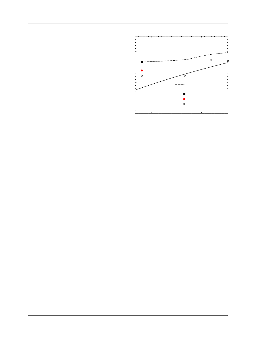
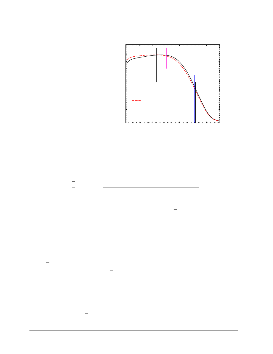
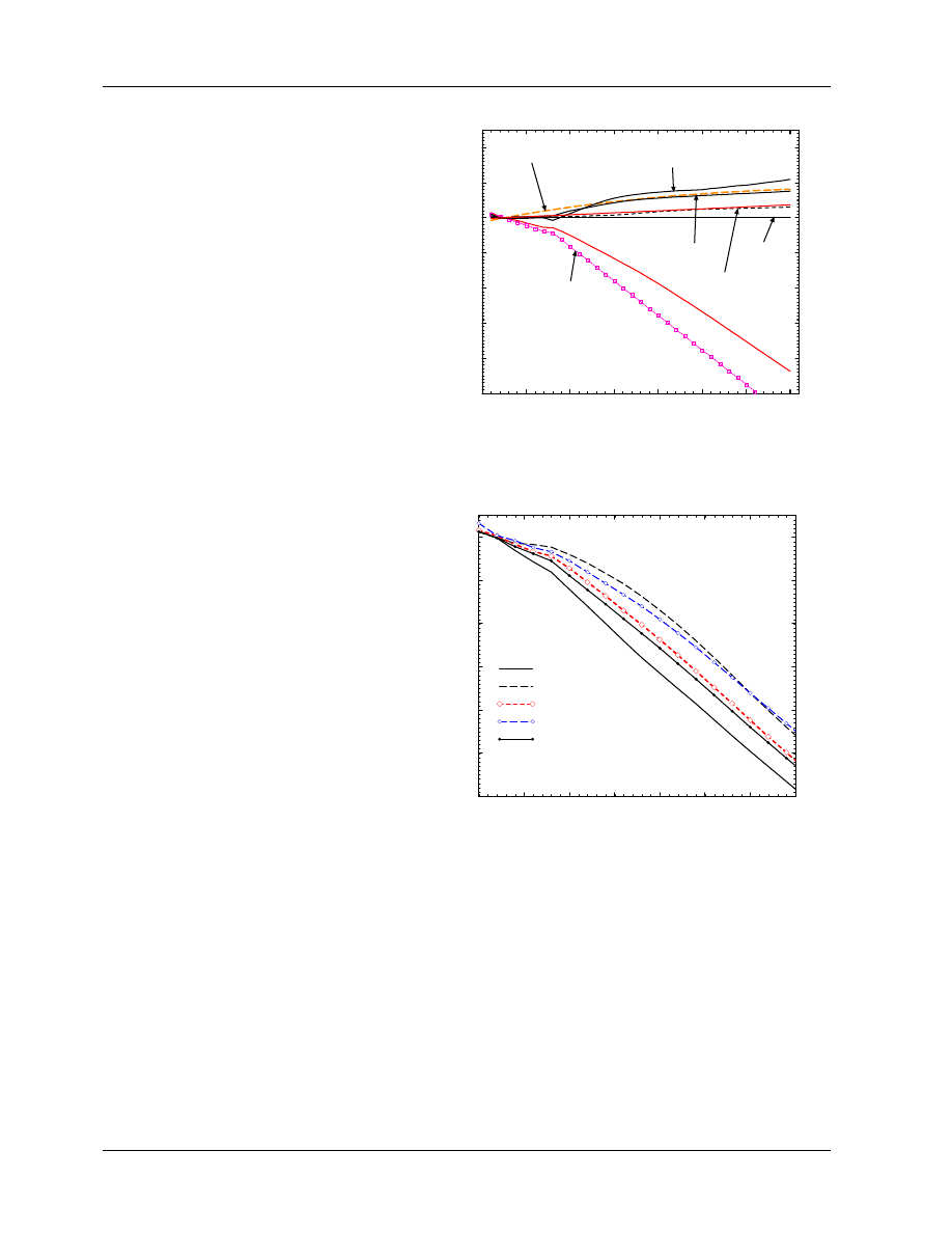
tions. Many other protocols have used the measured data of Johansson et al (1977) but as shown in figure 1
there are considerable differences amongst the original data, the TG–21 data and what is recommended in
the IAEA Code of Practice (1987).
It is clear that the gradient correction factor represents a significant uncertainty in present dosimetry pro-
4. ION CHAMBERS
4.A. Theory
page 8
D.W.O. Rogers
Figure 1: Value of P
repl
(= P
gr
in a photon
beam), for a 6.4 mm cavity, as a function
of beam quality specified by TPR
20
10
.
The
AAPM values are from TG–21, based on
the calculations of Cunningham and Sontag
(1980). The IAEA values are the effective
values (determined as described in Rogers
(1992c)) corresponding to the offsets used by
the IAEA Code of Practice (1987), which were
nominally based on the work of Johansson
et al (1977) which is shown as diamonds.
0.55
0.60
0.65
0.70
0.75
0.80
TPR
20,10
0.975
0.980
0.985
0.990
0.995
1.000
P
repl
AAPM
IAEA (effective)
AAPM
60
Co
IAEA
60
Co
Johansson et al
kqfig3
P
repl
for 6.4 mm diameter cavity
tocols. It is also worth noting that another way to correct for the gradient is used by the IAEA Code of
Practice (1987), viz. the effective point of measurement approach. This same approach is recommended
for measuring depth-dose or depth-ionization curves by the AAPM’s TG–25 on electron beam dosimetry
(Khan et al 1991). The method treats the point of measurement as being slightly up-stream of the center of
the ion chamber. For electron beams, both groups recommend an offset of 0.5r where r is the radius of the
cylindrical chamber’s cavity and for photon beams the shift correction is 0.75r. It must be emphasized that
if one is using a P
repl
value in photon beams for reference dosimetry, then the effective point of measurement
of a cylindrical chamber must be taken as it’s center.
The Fluence Correction Factor, P
fl
.
The other component of P
repl
is the fluence correction, P
fl
, which corrects for other changes in the electron
fluence spectrum due to the presence of the cavity. Corrections for changes in the electron fluence are only
needed if the ion chamber is in a region where full or transient charged particle equilibrium has not been
established, i.e. in the buildup region or near the boundaries of a photon beam or anywhere in an electron
beam.
Fluence corrections are not required for photon dose determinations made at or beyond d
max
in a broad
beam because transient electron equilibrium exists. The Fano theorem tells us that under conditions of
charged particle equilibrium the electron spectrum is independent of the density in the medium (see p
255, Attix (1986)). To the extent that the cavity gas is just low-density medium material, this theorem
tells us that the electron fluence spectrum is not affected by the cavity except in the sense of the gradient
correction discussed above, which in essence accounts for there being transient rather complete charged
particle equilibrium. Hence no fluence correction factor is needed in regions of transient charged particle
equilibrium.
In electron beams there are two competing effects. The in-scatter effect which increases the fluence in
the cavity because electrons are not scattered out by the gas and the obliquity effect which decreases
the fluence in the cavity because the electrons go straight instead of scattering. The in-scatter effect tends
to dominate, especially at low energies and P
fl
can be up to 5% less than unity for cylindrical chambers
at d
max
in electron beams. TG–21 tabulates recommended values for cylindrical chambers as a function
of the mean energy of the electrons at the point of measurement and recent measurements have confirmed
these values for a Farmer-like ion chamber (Van der Plaetsen et al 1994). The fluence effect is so large at
low energies that it becomes important to use plane-parallel chambers for these beams since P
fl
has been
shown to be unity for well-guarded plane-parallel chambers (Mattsson et al 1981; Van der Plaetsen et al
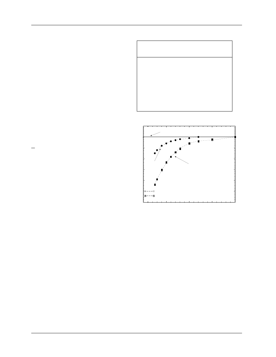
1994). However, the AAPM’s TG–39 on the calibration of plane-parallel chambers (Almond et al 1994) has
recommended non-unity values of P
fl
for both the Markus and Capintec plane-parallel chambers (see fig 2).
4. ION CHAMBERS
4.A. Theory
Dosimetry Fundamentals: 1996 AAPM Summer School
page 9
Table 2: P
cel
correction factor required for
farmer-like chambers with an aluminum
electrode of 1 mm diameter, based on the
calculations of Ma and Nahum (1993). Fac-
tors apply past d
max
in photon beams and
near d
max
or 0.6 R
50
− 0.1 cm in electron
beams. The %dd(10)
x
values exclude electron
contamination (see section 5.B.). Note that
P
cel
as defined here is consistent with the
other correction factors but is not the same
as the IAEA’s global P
cel
correction.
Beam Quality
P
cel
NAP/MeV
TPR
20
10
%dd(10)
x
photons
60
Co
0.58
56%
0.9926(15)
4MV
0.62
62%
0.9935(7)
6MV
0.67
67%
0.9930(11)
10MV
0.73
72%
0.9945(9)
15MV
0.76
78%
0.9955(16)
24MV
0.80
86%
0.9957(9)
electrons
<13 MeV
1.000
≥13 MeV
0.998
All the recommended values of P
fl
apply ONLY at d
max
since that is where they were measured (Johansson
Figure 2:
The P
fl
factors for plane-
parallel chambers recommended by TG–39
(Almond et al 1994) plus cubic fits to the
curves for the Markus and Capintec cham-
bers. The factors are given as a function of
E
z
(E in the figure), the mean energy at the
depth of measurement.
0
5
10
15
20
E
z
/ MeV
0.94
0.95
0.96
0.97
0.98
0.99
1.00
1.01
P
fl
TG−39 Fluence correction factors for plane−parallel chambers
P
fl
=0.9679 +0.0091 E −0.00094 E
2
+3.36.10
−5
E
3
P
fl
=0.9276 +0.0138 E −0.00091 E
2
+2.03.10
−5
E
3
Pfl_pp
NACP, Exradin, Holt
Markus
Capintec
et al 1977; Van der Plaetsen et al 1994) and strictly speaking, they are not appropriate for corrections of
depth-dose curves as sometimes suggested (e.g. Khan (1991)), although this is probably better than making
no correction.
4.A.6)
The Central Electrode Correction Factor, P
cel
Cylindrical chambers have central electrodes in their cavities and these have some effect on the chamber
response. For electrodes made out of the same material as the phantom, any effect of the electrode is
properly part of P
fl
. Any further effects due to the electrode being made of another material is properly
part of P
wall
but it is useful to separate out this effect and call it P
cel
if the electrode material is different
from the wall material. The effect is non-negligible for those widely used chambers which have aluminum
electrodes to give a flat energy response in low-energy x-ray fields (e.g. many NEL and PTW chambers). A
set of highly precise Monte Carlo calculations has been reported (Ma and Nahum 1993). The first important
result of that work is that 1 mm graphite electrodes have no effect on the response in a water phantom
(as expected since P
fl
is unity in photon beams and the difference between a water and graphite electrode
should be negligible). In electron beams the effects are also small (<0.2%) and are in principle included in
P
fl
and/or P
wall
. However, for 1 mm diameter aluminum electrodes the effect in photon beams is an increase
in response by 0.43 to 0.75%, requiring the correction factors in table 2. These data can be generated and
4. ION CHAMBERS
4.A. Theory

page 10
D.W.O. Rogers
extrapolated using:
P
cel
= 0.9862 + 0.000112(%dd(10)
x
).
(12)
The effects in electron beams are quite small and vary with depth. However, the effect on dosimetry in
electron beams is actually larger than in photon beams because, in essence, the final dose is multiplied by
P
cel
(e
−
)/P
cel
(
60
Co) and the factor in the denominator is quite large (see section 6.A.3).
4.B.
Practical Considerations
4.B.1)
Correction for Ion Recombination, P
ion
In general, ion chambers do not collect all the charge released in the air cavity and the factor P
ion
corrects
for this lack of 100% charge collection.
M
0
= M P
ion
[C or rdg],
(13)
where M
0
is the charge released in the ion chamber and M is the charge collected. This correction is
fairly well understood (see the review by Boag (1987)) and there is a standard technique for evaluating the
correction which involves measuring the charge collected at 2 voltages and then determining the correction
required (see Weinhous and Meli (1984)). Although the TG–21 protocol recommended a voltage ratio of 2
for these measurements, the underlying theory requires a ratio of 2.5 or more.
Although this correction is reasonably well understood, ion chambers with large correction factors (say >2%
correction), should probably not be used since the uncertainty in the correction may become unacceptable.
It must be emphasized that this correction depends on the dose to the air in the ion chamber per pulse.
Thus, if either the dose rate or the pulse rate at a constant dose rate are varied, then P
ion
must be re-
evaluated. This variation would even affect measurement of a depth-dose curve if an instrument with a large
value of P
ion
was being used.
4.B.2)
Temperature and Pressure Corrections
Temperature and pressure variations affect the mass of air inside an ion chamber. Since the total charge
produced depends on the product of the dose to the gas and the mass of the gas (eq.(5), it also depends on the
temperature and pressure. Since ion chambers are all calibrated under standard conditions of temperature
and pressure, i.e. for a given mass of air in them, it is essential to normalize all readings of ion chamber
charge back to these same reference conditions (T
o
= 22
◦
C and pressure at P
o
= 101.33 kPa, 1 atmosphere).
This is done using:
M = M
o
101.33
P
×
T + 273.2
273.2 + 22.0
[C or rdg],
(14)
where M is the corrected reading, M
o
is the uncorrected reading, T is the temperature in degrees celsius
and P is the pressure in kilopascals (not corrected to sea level).
4.B.3)
Waterproofing Sleeves
Since the protocol will require absorbed-dose calibration factors measured in a water phantom and also
clinical measurements in water, the issue of how to waterproof the chamber becomes important. There
are already good chambers on the market which are waterproof. This seems like a desirable goal. But for
chambers that are not, a waterproofing sleeve will be required. In eq.(10) there is an explicit term for a
waterproofing sleeve but as mentioned, the experimental data are not in particularly good agreement with
the theory (Hanson and Tinoco 1985; Gillin et al 1985; Ross and Shortt 1992). For sufficiently thin sleeves
of PMMA (< 1 mm) or latex rubber, the experimental data show that there is less than a 0.2% effect on
the chamber response which varies little with beam quality and thus can be ignored. The various calibration
laboratories are working on a calibration protocol which will incorporate the need for such a sleeve.
4. ION CHAMBERS
4.B. Practical Considerations

Dosimetry Fundamentals: 1996 AAPM Summer School
page 11
5.
BEAM-QUALITY SPECIFICATION
5.A.
Why Do We Need to Specify Beam Quality?
Clinically one must be able to identify accelerator beams for many reasons, and usually just referring to
the 12 MV beam or the 18 MeV beam is adequate. However, for reference dosimetry we need more precise
specification of the beam quality, Q, so that one can select the correct value of k
Q
in the dose equation, eq.(3).
As is shown below in fig. 9 and eq.(26), the value of k
Q
is dominated by the water to air stopping-power ratio
which varies by over 15% in clinical beams (from 1.13 for
60
Co beams to 0.98 for 50 MeV electron beams).
5.B.
Specification of Photon Beam Quality
The TG–21 protocol uses the quantity TPR
20
10
to specify photon beam quality when selecting
¡
L/ρ
¢
w
air
although it also uses the nominal accelerating potential (NAP) to specify other, less sensitive quantities.
The value of TPR
20
10
is determined by measuring the absorbed dose or ionization on the beam-axis at depths
of 20 cm and 10 cm for a constant source–detector distance and a 10 cm x 10 cm field at the plane of the
chamber (i.e. one must move the phantom, or at least its surface).
The idea of using measured ratios of ionization or dose at two depths was first introduced in the Nordic
dosimetry protocol to specify the accelerator energy (NACP 1980). The TG–21 protocol goes one step
further and directly associates the beam quality index with the stopping-powers ratios needed. This is based
on the work of Cunningham and Schulz (1984) who found a universal curve relating these two quantities
based on analytic calculations of stopping-power ratios and TPR
20
10
for a variety of clinical photon spectra.
Andreo and Brahme (1986) showed that for clinical photon spectra one could accurately calculate values of
TPR
20
10
using Monte Carlo techniques and found a curve relating stopping-power ratios for clinical beams
and TPR
20
10
. They also showed that for a given NAP there are up to 1.3% variations in the stopping-power
ratio. It is for this reason that TPR
20
10
is used rather than NAP. However, TPR
20
10
is also not an ideal beam
quality specifier because there are variations of over 1% in the stopping-power ratio associated with beams of
the same TPR
20
10
(see fig 3). Since eq.(25) below shows N
Q
D,w
is directly proportional to the stopping-power
ratio, this can be a problem for standards laboratories since their beams might not match those in the clinic,
and hence the value of N
Q
D,w
might not apply in the clinic for a beam of the same TPR
20
10
.
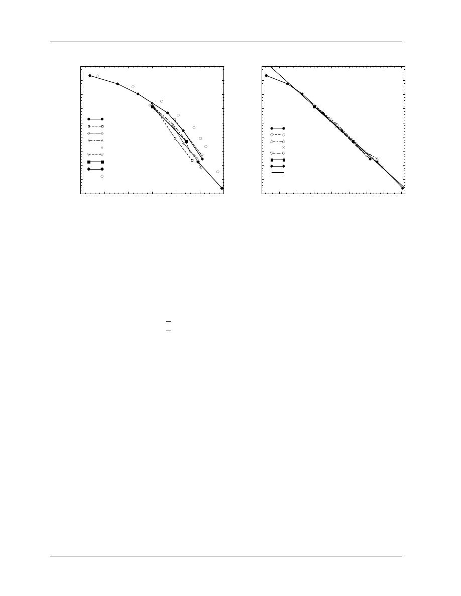
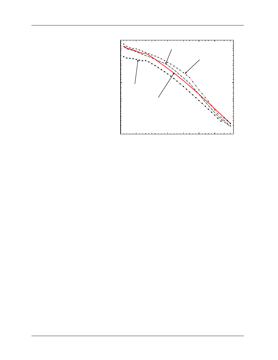
As seen in fig. 3, high-energy photon beams also lead to other problems with TPR
20
10
as a beam specifier.
The high-energy swept beams from the racetrack microtron accelerators have considerably different curves
of stopping-power ratios vs TPR
20
10
values compared to other “typical clinical beams”. Furthermore, for
high-energy beams, TPR
20
10
is an insensitive quality specifier. For example a 1% change in TPR
20
10
for values
near 0.8 leads to a 3 MV change in the nominal accelerating potential (near 20 MV) and a 0.4% change in
the water to air stopping-power ratio. In contrast, for values of TPR
20
10
near 0.7 a 1% change corresponds
to a 0.1% change in stopping-power ratio and only an 0.5 MV change in the NAP.
Manufacturers and others have often specified beam quality in terms of an NAP in MV which is not well
defined. The obvious definition in terms of the energy of the electrons from the accelerator is not very useful
because this energy is usually not well known. More importantly, the beam quality is strongly affected by the
type of beam flattening used (see LaRiviere (1989) and references therein for a good discussion). LaRiviere
proposed that the beam quality in MV should be specified in terms of %dd(10), the measured percentage
depth dose at 10 cm depth in a 10 × 10 cm
2
field at a source to surface distance (SSD) of 100 cm with
Q = 10
[%dd(10)−46.78]/26.09
[MV],
(15)
which is a good fit to the “experimental” data although there is scatter in the initial data caused by the lack
of a clear definition of Q.
Kosunen and Rogers (1993) took LaRiviere’s argument one step further and showed that for any
bremsstrahlung beam above 4MV, one has a linear relationship between stopping-power ratio and %dd(10)
x
5. BEAM-QUALITY SPECIFICATION
page 12
D.W.O. Rogers
0.55
0.60
0.65
0.70
0.75
0.80
0.85
TPR
20
1.05
1.06
1.07
1.08
1.09
1.10
1.11
1.12
1.13
1.14
stopping−power ratio (water/air)
spr vs. TPR
Mohan+
60
Co
Schiff−thin
Al−measurements
Pb−measurements
Be
Filtered Al
NRC standard
racetrack
mono−energetic
krfig2
10
Figure 3:
Water to air stopping-power ratios
vs
TPR
20
10
for nine families of photon spectra,
demonstrating variations when using TPR
20
10
as a
beam quality specifier. Flattened, i.e. practical beams
are shown as closed symbols.
From Kosunen and
Rogers (1993).
55
60
65
70
75
80
85
90
95
% depth dose at 10 cm depth
1.05
1.06
1.07
1.08
1.09
1.10
1.11
1.12
1.13
1.14
stopping power ratio (water/air)
spr vs. % depth dose at 10 cm depth
Mohan +
60
Co
Al−meas
Pb−meas
Be−meas
Filtered Al
NRC standards
racetrack
fit
krfig5
Figure 4: Water to air stopping-power ratios
vs %dd(10)
x
for the thick-target bremsstrahlung
&
60
Co spectra in figure 3. The straight line
shown is the fit to the sprs of the bremsstrahlung
beams given by eq.(16) with an rms deviation of
0.0013 and a maximum deviation of 0.003. From
Kosunen and Rogers (1993).
for the photon component of the beam. This is shown in figure 4 and the line is given by:
µ
L
ρ
w
air
= 1.2676 − 0.002224(%dd(10)
x
).
(16)
The problem with this relationship is that it applies only for photon beams with no electron contamina-
tion. In 10 × 10 cm
2
fields for beams above 10 MV, electron contamination affects the dose maximum and
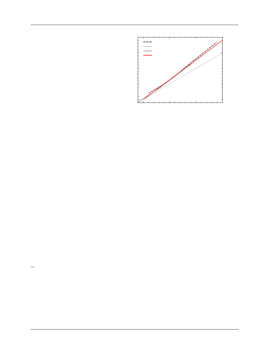
hence affects %dd(10), the measured % depth dose at 10 cm. Using 2 sets of measured data which demon-
strated considerable variation from machine to machine, estimates have been made of the effects of electron
contamination on %dd(10) (see fig 5) and the linear correction needed is given by:
%dd(10)
x
= 1.2667 (%dd(10)) − 20.0
[for %dd(10) > 75%].
(17)
For %dd(10) < 75% one need make no adjustments, %dd(10)
x
= %dd(10). Especially for high energies this
approach may lead to errors of up to 2% in the assigned value of %dd(10)
x
but as seen below, there is only
a 0.2% error in k
Q
values per 1% error in %dd(10)
x
.
Another approach for determining %dd(10)
x
has been investigated by Li and Rogers (1994). A 1 mm lead
foil is inserted in the accelerator beam immediately below the accelerator head. This removes from the beam,
all the electron contamination from the accelerator head (which is the source of the machine to machine
variation) and adds a known amount of electron contamination to the beam which can be taken into account.
For beams with %dd(10) greater than 70%, the value of %dd(10)
x
in the unfiltered beam is given by:
%dd(10)
x
= [0.9439 + 0.000804 (%dd(10))] %dd(10) − 0.15
[for %dd(10) > 70%]
(18)
where %dd(10) is measured in the filtered beam. For beams with %dd(10) < 70%, electron contamination
plays no role and %dd(10)
x
= %dd(10) − 0.15 where %dd(10) is measured in the filtered beam. The 0.15
5. BEAM-QUALITY SPECIFICATION
5.B. Specification of Photon Beam Quality
Dosimetry Fundamentals: 1996 AAPM Summer School
page 13
Figure 5: Two estimates of the effects of
electron contamination on %dd(10), based on
measured data with considerable fluctuations.
The adopted fit given by eq.(17) is shown as
the darker solid line. Modified from Kosunen
and Rogers (1993).
75
80
85
90
measured %dd(10)
m
75
80
85
90
95
theoretical %dd(10)
correction of %dd(10) for electron contamination
LaRiviere’s fit vs calc
RPC data vs calc
no contamination
adopted value
krfig7r
corrects for the slight beam hardening by the lead filter. However, for the low-energy beams it is more direct
just to use %dd(10)
x
= %dd(10) where %dd(10) is measured in the unfiltered beam.
There is another aspect of measuring depth-dose curves with a cylindrical ion chamber which must be taken
into account, viz. the change in the gradient correction factor (roughly a 1% effect). There is no gradient
correction factor at dose maximum but at 10 cm depth, the correction varies with the beam quality and
chamber radius (P
repl
correction, see section 4.A.5). For measuring depth-dose curves, instead of using P
repl
,
this correction can be handled by treating a cylindrical or spherical ion chamber’s point of measurement as
being at 0.75r upstream of the center of the chamber, where r is the radius of the chamber cavity (this is
the point of measurement used by the IAEA Code of Practice and thus different from the TG–21 values
of P
repl
, as seen in figure 1). Note that for all other measurements in the TG–51 protocol, the point of
measurement of cylindrical and spherical chambers is considered to be at the center. Although the issue of
gradient corrections can be avoided by using diode detectors to measure the depth-dose curve, it is essential
to ensure the diode is actually measuring dose since they can be very sensitive to low energy components in
the beam which change with depth.
In summary, for photon beams it appears that the widely used %dd(10) is an excellent beam quality specifier.
Not only does it define a single value of the stopping-power ratio needed for photon beam dosimetry, it also
maintains its sensitivity in high-energy photon beams and is relatively easy to measure. Some care must be
taken to account for the changes in gradient effects at d
max
and at 10 cm depth, and also to account for
electron contamination for beams with %dd(10)
x
over 70%.
5.C.
Specification of Electron Beam Quality
5.C.1)
Determination of R
50
Most protocols specify electron beam quality in terms of the mean energy of the beam at the patient surface,
E
o
, which is determined by measuring R
50
, the depth at which the dose in a broad beam falls to 50% of its
maximum value. With TG–21 there was some discussion about using depth-dose or depth-ionization curves
and SSD = 100 cm vs correcting to parallel beam conditions (Wu et al 1984). Although the effects are not
large, the correct procedure is to use the SSD corresponding to whatever use is being made of R
50
and to
use the value of R
50
from the depth-dose curve. The problem is that to determine the depth-dose curve
requires converting the ionization to dose using stopping-power ratios and these require knowledge of the
R
50
! One way out of this loop is to determine I
50
from the depth-ionization curve (using the effective point
of measurement technique discussed in section 4.A.5) and then use the relationship developed by Ding et al
(1995):
R
50
= 1.029I
50
− 0.063
[cm]
(2.2 < I
50
< 10.2 cm).
(19)
5. BEAM-QUALITY SPECIFICATION
5.C. Specification of Electron Beam Quality
page 14
D.W.O. Rogers
Figure 6: Difference between a
depth-ionization and depth-dose
curve for a 12 MeV beam at
SSD = 100 cm.
The depths
of dose and ionization maxima
and 50% values are shown, as
well as the reference depth,
d
ref
= 0.6R
50
− 0.1 (cm) (dis-
cussed in section 5.C.4). Based
on data from Ding et al (1997).
0
1
2
3
4
5
6
7
depth /cm
0
10
20
30
40
50
60
70
80
90
100
110
relative dose
12 MeV beam from Clinac 2100C
dose in water
ionization in water
dose_ion
d
ref
d
max
I
max
I
50
R
50
This equation only applies to beams with initial energies between 5 and 25 MeV and is a more accurate
version of the correction given in the IAEA Code of Practice(1987). Below 5 MeV no correction is needed
and for higher-energy beams, fig.19 of the original paper should be used.
Another approach is to use I
50
as a first approximation to R
50
and to use a universal function developed
by et al. (1996) which gives the water to air stopping-power ratio as a function of depth, z, and R
50
with
adequate accuracy for converting from depth-ionization to depth-dose curves, viz.:
µ
L
ρ
w
air
(z, R
50
) =
a + b(lnR
50
) + c(lnR
50
)
2
+ d(z/R
50
)
1 + e(lnR
50
) + f (lnR
50
)
2
+ g(lnR
50
)
3
+ h(z/R
50
)
(20)
for z/R
50
ranging between 0.02 and 1.2, R
50
ranging between 1 and 19 cm and with: a = 1.0752; b =
−0.50867; c = 0.088670; d = −0.08402; e = −0.42806; f = 0.064627; g = 0.003085; h = −0.12460. Using
these data allow direct conversion in terms of R
50
without determining E
o
and tables of stopping-power
ratios vs depth as a function of E
o
.
A third alternative is to determine the depth-dose curve using a good-quality diode detector which responds
as a dose-detector (Rikner 1985; Khan et al 1991) and then determine R
50
.
5.C.2)
The mean energy at the phantom surface, E
o
The TG–21 and IAEA protocols use the value of R
50
(in cm) to determine the mean energy at the phantom
surface, E
o
using:
E
o
= 2.33R
50
[MeV].
(21)
Rogers and Bielajew (1986) provided more accurate data for making this conversion which accounted for
the finite SSD used in the measurement of R
50
and more accurate Monte Carlo calculations than those
that had been used to establish the 2.33 MeV/cm factor used in TG–21. These more accurate data were
recommended by TG–25 on electron beam dosimetry (Khan et al 1991). However, all of the previous Monte
Carlo calculations were done using mono-energetic electron beams. Ding et al (1996) have recently shown
that E
o
and R
50
do not correlate very well with the data of Rogers and Bielajew (1986) because scattered
electrons in the beam affect E
o
but have little effect on R
50
. On the other hand, the direct electrons in the
beam, i.e. those that do not hit applicators or jaws etc, do correlate well with the previous data.
5. BEAM-QUALITY SPECIFICATION
5.C. Specification of Electron Beam Quality
Dosimetry Fundamentals: 1996 AAPM Summer School
page 15
5.C.3)
Problems with stopping-power ratios using mono-energetic beams
In the TG–21 and IAEA protocols, the water to air stopping-power ratios needed for electron beam dosimetry
are based on Monte Carlo calculations for mono-energetic electron beams. However, the energy and angular
distributions of the real electron beams in the clinic have an effect on the stopping-power ratios (Andreo et al
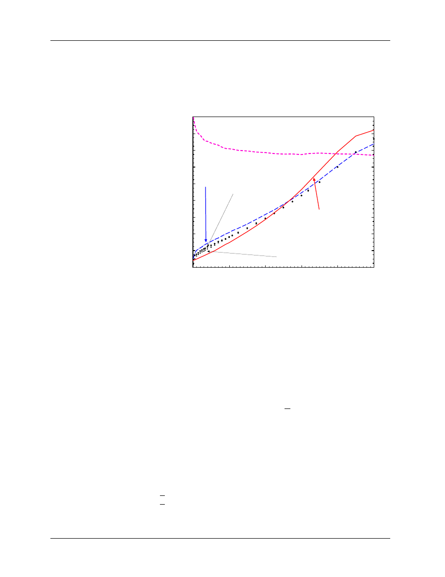
1989; Andreo and Fransson 1989; Ding et al 1995). Figure 7 shows an example of the stopping-power ratios
Figure 7: Various Monte Carlo
calculated water to air stopping-
power ratios vs
depth.
The
solid line represents the spr one
would obtain following TG–21,
the long dash, that from the
complete simulation and the
other curves include only some
components of the beam. Based
on data from Ding et al (1995).
0
2
4
6
8
10
depth in water /cm
0.95
0.97
0.99
1.01
1.03
1.05
1.07
1.09
1.11
stopping−power ratios
photons only
e
−
& photons
protocol/TG21,IAEA
e
−
with no angular distn
e
−
only
spr_eg
realistic 20 MeV beam from an SL75/20
calculated for a realistic beam simulation. The photon component of the beam and the electron spectrum
have a pronounced effect on the stopping-power ratio although the angular distribution of the electrons has
little effect. The size of the error made by assuming a mono-energetic beam varies with depth. The error
can be up to 1.2% at d
max
. Thus, it is important to take into account the realistic nature of the beam when
doing stopping-power ratio calculations. Ding et al (1995) gave a general procedure which uses the size of
the bremsstrahlung tail to estimate the correction needed at d
max
for a stopping-power ratio determined
assuming a mono-energetic beam.
5.C.4)
Direct use of R
50
as beam quality specifier
Although the procedure developed by Ding et al (1995) takes into account the realistic nature of the beam,
it is fairly complex to use, requiring several steps and, since d
max
varies considerably, a complete set of
stopping-power ratios as a function of depth and incident mean energy E
o
. et al. (1996) found a much
simpler solution, which by-passes much of the complexity of the previous methods and yet continues to take
into account the realistic nature of the electron beams. The essence of the proposal is to change the reference
depth for electron beam dosimetry from d
max
to d
ref
:
d
ref
= 0.6R
50
− 0.1
[cm].
(22)
For low-energy electron beams this depth corresponds closely to d
max
but for higher-energy beams it is past
d
max
, but still usually well above a dose of 90% (see e.g. fig.6). The surprising feature about using this
reference depth is that the water to air stopping-power ratio is given by:
µ
L
ρ
w
air
(d
ref
) = 1.2534 − 0.1487(R
50
)
0.2144
,
(23)
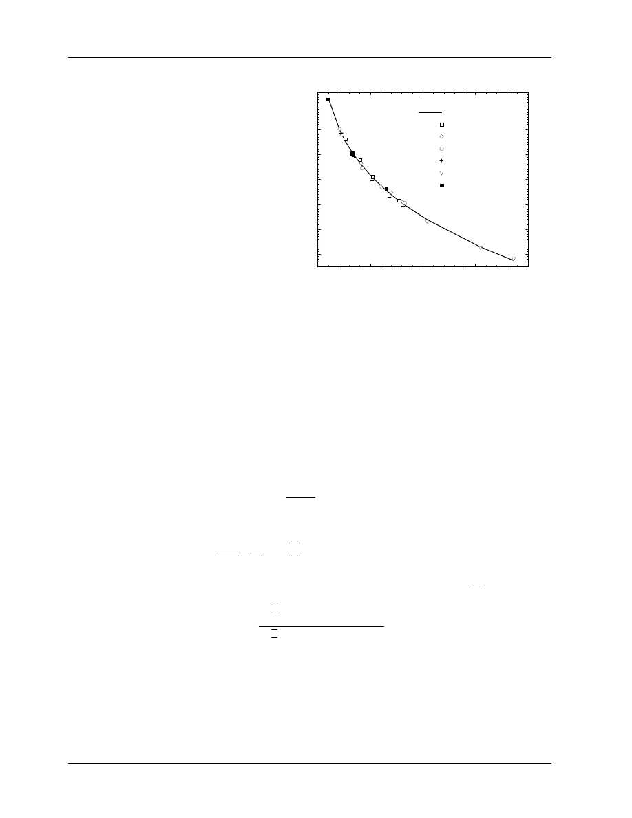
for all clinical beams (the raw data are shown in figure 8). The rms deviation of the data about this fit is
5. BEAM-QUALITY SPECIFICATION
5.C. Specification of Electron Beam Quality
page 16
D.W.O. Rogers
Figure 8: Water to air stopping-power ratio
at the reference depth d
ref
= 0.6R
50
− 0.1 cm
as a function of R
50
.
The fit is given by
eq.(23). From et al. (1996).
0
5
10
15
20
R
50
/ cm
0.98
1.00
1.02
1.04
1.06
1.08
1.10
stopping−power ratio at reference depth
Fit
Clinac 2100C
SL75−20
KD2
Therac 20
MM50
NPL
6p0m1_fit
0.16% with a maximum deviation of 0.26%. This equation replaces an entire page of stopping-power ratio
data in the TG–21 protocol and is considerably more accurate since it applies to realistic beams. Also, it
avoids the need to establish the mean energy at the surface of the phantom, a quantity which is not well
defined by R
50
(see section 5.C.2).
6.
VALUES OF k
Q
6.A.
Calculation of k
Q
Values
6.A.1)
An equation for k
Q
From eq.(1) for the dose to water in terms of the absorbed-dose calibration factor, one has:
N
Q
D,w
=
D
Q
w
M P
ion
[Gy/C].
(24)
Using eqs.(8), (9) and (13) for D
air
, D
w
and M
0
, gives:
N
Q
D,w
=
K
h
m
air
µ
W
e
air
µ
L
ρ
w
air
P
wall
P
fl
P
gr
P
cel
[Gy/C].
(25)
Using eq.(2) to define k
Q
, substituting eq.(25) at the two beam qualities, and assuming
¡
W
e
¢
air
is constant,
one has:
k
Q
=
h³
L
ρ
´
w
air
P
wall
P
fl
P
gr
P
cel
i
Q
h³
L
ρ
´
w
air
P
wall
P
fl
P
gr
P
cel
i
60
Co
,
(26)
where the numerator and denominator are evaluated for the beam quality Q of interest, and the calibration
beam quality,
60
Co, respectively.
6.A.2)
Photon Beams
Calculation of k
Q
for a given ion chamber in a photon beam is reasonably straight forward. One expects
this formalism to be more accurate than a formalism starting from air-kerma standards since in this case,
6. VALUES OF K
Q
Dosimetry Fundamentals: 1996 AAPM Summer School
page 17
only ratios of the same quantity at different beam qualities are needed rather than the value itself. For
example, the effective value of the factor P
repl
differs by at least 0.4% and up to 0.8% for the IAEA or
TG–21 approaches (the solid and dashed lines in fig.(1)). However, the difference in the ratio of these values
is never more than 0.4% when calculating k
Q
. In effect, by using a primary standard for absorbed dose at
60
Co energy, the uncertainty due to P
repl
is reduced because this quantity is, in some senses, “ included” in
the primary standard.
In calculating k
Q
with eq.(26), the values of
¡
L/ρ
¢
w
a
as a function of %dd(10)
x
are calculated using eq.(16)
for %dd(10)
x
≥ 62.2%, and are interpolated linearly from there (1.1277) to the
60
Co point at 56.3%
(1.1335)(Kosunen and Rogers 1993). Since the variation in
¡
L/ρ
¢
w
a
dominates the beam quality dependence,
we expect the value of k
Q
to be nearly linear with %dd(10)
x
, at least for beams with %dd(10)
x
> 62.2%.
Ignoring issues about the accuracy of eq.(10), it can be used to calculate the P
wall
term and if a thin-
walled waterproofing sheath has been used, it can be ignored and τ taken as 0.0 (see section 4.B.3). The
physical data needed for this P
wall
equation are taken from the IAEA Code of Practice (1987) since it
uses stopping powers and mass energy absorption coefficients which are consistent with those used in the
standards laboratories. These data are tabulated as a function of TPR
20
10
. Since the variation in the overall
P
wall
factor is small, one can use a value of TPR
20
10
from a fit to standard clinical beam data which gives
(Rogers and Booth 1996):
TPR
20
10
= −0.6391 + 0.029348 (%dd(10)
x
) − 0.00014498 (%dd(10)
x
)
2
.
(27)
Note, this equation applies to %dd(10)
x
with electron contamination removed and it is not accurate enough
to make the conversion from %dd(10)
x
to TPR
20
10
in general: if it were, there would be no advantage in
changing beam quality specifiers! The variation in P
wall
factors for typical thin-walled ion chambers in
photon beams is less than 1%.
The P
fl
term in eq.(26) is 1.00 in a photon beam (see section 4.A.5) and thus does not enter the calculation
of k
Q
.
The P
gr
term can be calculated using the data in fig.(1). Despite the large differences in the effective values
used by the protocols, the difference in the ratio is quite small. Since the variation in the TG–21 value is
close to the variation in the original data of Johansson et al (1977), and for continuity with past practice, it
is easiest to use the value of P
gr
from the TG–21 protocol, which is based on the work of Cunningham and
Sontag (1980). This parameter is a function of beam quality and the diameter of the chamber’s gas cavity.
For a Farmer-like chamber it only varies by about 0.4% as a function of beam quality.
The P
cel
term, which only applies for chambers with an aluminum electrode, is calculated using eq.(12). For
a 1 mm diameter aluminum electrode (the only size for which there are data), the effect on k
Q
is an increase
of less than 0.4%.
Figure 9 presents calculated k
Q
values for an NE2571 cylindrical Farmer chamber with 0.065 g/cm
2
walls,
6.3 mm cavity diameter and 1 mm diameter aluminum electrode. It also shows the contribution of each of
the components in eq.(26), e.g. (P
wall
)
Q
/(P
wall
)
60
Co
= (P
wall
)
Q
60
Co
. For comparison, two additional curves
are shown. One is for the effective P
repl
component from the IAEA Code of Practice and the second shows
the effect on P
wall
of considering a 1 mm thick PMMA waterproofing sheath as in eq.(10). This figure
indicates, most importantly, that the stopping-power ratio dominates the change with beam quality in k
Q
and hence the calibration factor N
Q
D,w
. Secondly, the effect of ignoring the sheath is about 0.3% at high
energies, a value which is consistent with the experimental data (see section 4.A.4). Finally, the uncertainty
in the correct value of P
repl
continues to be the major uncertainty in the calculation of k
Q
.
For cylindrical ion chambers with walls thinner than 0.25 g/cm
2
, there is a “universal” curve for k
Q
which
agrees with the individual calculations within ±1% and for Farmer-like chambers this is further improved to
an accuracy of ±0.7% (Rogers 1992c). Figure 9 shows that this is possible because the major determinant
of k
Q
is the stopping-power ratio and this is independent of the ion chamber. The next largest factor is the
P
wall
factor and this is mostly determined by the wall material. Thus, calculated k
Q
values for Farmer-like
ion chambers of a particular wall material are all very nearly the same. Figure 10 shows such a set of k
Q
values which apply within a few tenths of a percent for all commercial ion chambers for which calculations
6. VALUES OF K
Q
6.A. Calculation of k
Q
Values
page 18
D.W.O. Rogers
Figure 9: Calculated values of k
Q
and its
components for an NE2571 Farmer-like ion
chamber with 0.065 g/cm
2
graphite walls,
inner diameter of 6.3 mm and an aluminum
electrode with 1 mm diameter. The TG–21
P
repl
= P
gr
component (short dash) and the
P
cel
component defined here (solid line) are
almost the same. Also shown for comparison
are the P
wall
component including considera-
tion of a 1 mm PMMA waterproofing sheath
and the effective P
repl
component based on
the IAEA Code of Practice.
55
60
65
70
75
80
85
90
%dd(10)
0.95
0.96
0.97
0.98
0.99
1.00
1.01
1.02
k
Q
and its components
k
Q
(spr)
60
Co
(P
fl
)
60
Co
AAPM (P
gr
)
60
Co
(P
wall,sheath
)
60
Co
& (P
cel
)
60
Co
(P
wall
)
60
Co
fig8
Q
IAEA (P
gr
)
60
Co
Q
Q
Q
Q
Q
Q
NE2571
have been done (although there is slightly more spread than in the original paper (Rogers 1992c) since the
P
cel
correction has been included here).
Figure 10:
Calculated values of k
Q
for
cylindrical Farmer-like ion chambers with the
walls shown. These values apply within a few
tenths of a percent for all chambers studied
(Rogers (1992d), updated).
55
60
65
70
75
80
85
90
%dd(10)
0.94
0.95
0.96
0.97
0.98
0.99
1.00
k
Q
A−150
C−552
Delrin
graphite
PMMA
k
Q
for chambers of walls
shown
standard_kQ
Figure 11 compares the present results to results that would be obtained using previous protocols and the
data in them. The change from TG–21 values is not large, and mostly accounted for by the change in
the underlying stopping powers being used now. However, the difference would be slightly larger if there
were no aluminum electrode since this was not considered in TG–21 and it affects this chamber. Also, part
of the difference comes from the uncertainty introduced by interpolating the previous AAPM data which
was presented as a function of TPR
20
10
whereas here %dd(10)
x
is used. The IAEA values differ considerably
because of how they treated
60
Co beams as a special case. Note also that the IAEA’s correction for the
central electrode only “kicks-in” for high-energy beams (%dd(10)
x
>87%), but when it does, the value it
uses is close to that used here (although the definitions differ so that P
cel
(IAEA) = P
cel
(Q)/P
cel
(
60
Co)).
PROT, a program for calculating k
Q
for arbitrary chambers has been written (Rogers and Booth 1996). It is
based on the program described earlier (Rogers 1992c) but updated to take into account the changes described
above. It will be made available via the WWW at the address given at the beginning of this references.
There are also several very extensive sets of calculated k
Q
values available in the literature (Andreo 1992;
Rogers 1992c) but these are given as a function of TPR
20
10
and do not include the P
cel
correction used here.
6. VALUES OF K
Q
6.A. Calculation of k
Q
Values
Dosimetry Fundamentals: 1996 AAPM Summer School
page 19
Figure 11:
Values of k
Q
for
NE2571
cylindrical
chamber
with 0.065 g/cm
2
graphite
walls, cavity of 6.3 mm and
1 mm diameter aluminum elec-
trode. Results use eq.(27). Part
of the difference for TG–21 is
that previous data are tabulated
vs TPR
20
10
and require a conver-
sion from %dd(10)
x
to TPR
20
10
.
The current results are also
shown using this approach to
show the variations introduced.
55
60
65
70
75
80
85
90
%dd(10)
0.95
0.96
0.97
0.98
0.99
1.00
k
Q
IAEA
current
current (%dd from TPR)
TG−21
kQ_fig9
k
Q
for NE2571
6.A.3)
Electron Beams
Calculation of k
Q
for electron beams is considerably more complex than for photon beams since the quantities
in the numerator and denominator of eq.(26) are different, not just the same quantities at slightly different
beam qualities as in the photon beam case. Also, for electron beams one must handle plane-parallel chambers
since these are recommended for use in low-energy beams.
For cylindrical chambers, the denominator of eq.(26) is calculated in the same manner as in section 6.A.2).
For plane-parallel chambers the denominator evaluated in
60
Co beams requires some new considerations. The
stopping-power ratio is the same as in the cylindrical chamber case. The P
repl
factor for plane-parallel cham-
bers is unity (see section 4.A.5). The P
cel
factor is unity since there are no central electrodes. The P
wall
factor is not covered by eq.(10) which only applies to chambers where the wall uniformly surrounds the
cavity. For plane-parallel chambers, the front wall is often much thinner than the rest of the chamber and of
a different material. Also, any insulator material immediately behind the cavity may have a dramatic effect
on the response (up to 5%) and P
wall
must take this into account (Rogers 1992a; Almond et al 1994). In the
TG–39 report on electron beam dosimetry with plane-parallel chambers (which, for consistency with TG–21
did not use the ICRU Report 37 stopping powers being used here), values of P
wall
in a
60
Co beam were
provided for the case in which the phantom material matched the major component of the chamber (graphite
for an NACP chamber, PMMA for a Markus chamber, etc). For the present purposes, we need the value of
P
wall
in a water phantom, which also implies there may be a waterproofing cap on the plane-parallel cham-
ber. Using the same methods as previously, I have done a further series of Monte Carlo calculations and
derived the necessary values for various commercial plane-parallel chambers (see table 3). Note that these
values are for
60
Co only, and since values of P
wall
are not usually available for other photon beam qualities,
plane-parallel chambers are not suitable for absorbed-dose measurements in photon beams until there are
measured values of P
wall
, or preferably k
Q
, available.
With P
wall
values available, all the factors in the denominator of eq.(26) are known (the denominator
is just N
60
Co
D,w
/N
gas
in TG–21 terminology). These values of the denominator are calculated and have a
relatively large systematic uncertainty. Once it is decided how to waterproof each of these chambers properly,
something some of the manufacturers have already done, it would be preferable to have these values measured.
For the numerator in eq.(26) for k
Q
for electron beams, the stopping-power ratio term is given by eq.(23)
since these values are all for the reference depth, 0.6R
50
− 0.1 cm. I will take the P
wall
term to be unity, with
6. VALUES OF K
Q
6.A. Calculation of k
Q
Values
page 20
D.W.O. Rogers
Table 3: P
wall
correction factor for plane-parallel chambers in a phantom of the major material of the
chamber or water, irradiated by
60
Co beams (Rogers tted). Uncertainties shown are statistical (68%
confidence) and there is an inherent 1% systematic uncertainty. For the in-water case, it is assumed a 1 mm
slab of the major material of the chamber is used for waterproofing.
Chamber (major material)
P
wall
in
60
Co beam
in homogeneous phantom
in water with 1 mm sheath
Attix Chamber (RMISW)
1.012(3)
1.023(3)
Capintec PS033 (polystyrene)
0.948(1)
0.974(3)
Exradin P11 (polystyrene)
0.991(5)
1.021(3)
Holt (polystyrene)
0.992(2)
0.994(4)
a)
Markus (PMMA)
0.992(2)
0.998(2)
NACP (graphite)
1.018(2)
1.018(2)
b)
PTB/Roos (PMMA)
0.995(2)
1.002(2)
a)
4 mm polystyrene front face in place over entire sheet.
b)
Thin mylar sheet over front graphite face for waterproofing.
the caveat expressed in section 4.A.4), that for plane-parallel chambers, there may be a need to include a
factor varying between 1.0 and 1.02, depending on the energy and material of the back wall of the chamber.
The P
cel
factor for cylindrical chambers with 1 mm aluminum electrodes is 1.000 or 0.998 as given in table 2.
The remaining correction in the numerator of eq.(26) for electron k
Q
values is P
repl
= P
fl
P
gr
. For plane-
parallel chambers there is no problem with the gradient correction, P
gr
, which is taken to be 1.00 in electron
beams because the point of measurement is taken at the front of the air cavity. For well-guarded plane-
parallel chambers, P
fl
is also taken as unity, but this is not the case for the Markus and Capintec chambers
(section 4.A.5), and their tabulated P
fl
values are given here by the expressions in fig 2 using the same
techniques as described below for estimating the mean energy, E
z
, at d
ref
. Also, most data for these
chambers have been measured at d
max
and there are likely variations at other depths.
For cylindrical chambers, handling these correction factors is more complex. Values of P
fl
for cylindrical
chambers are a function of chamber radius and the mean energy at the point measurement and these values
are given in TG–21 (see section 4.A.5). Despite the fact that these values are only known for d
max
and we now
need them at d
ref
, we will assume that the values in TG–21 still apply (and encourage some measurements
to establish the correct value). For low-energy beams these values apply because d
ref
is still at d
max
. At
higher energies, the correction becomes less important and thus the approximation being used is probably
acceptable. We still need to evaluate E
z
, the mean energy at the point of measurement. Traditionally this
is given by the Harder relationship:
E
z
= E
o
(1 − z/R
p
),
(28)
where E
o
is the mean energy at the surface and R
p
is the practical range (ICRU 1984a). This parameter-
ization unfortunately breaks with the proposed beam quality specification in terms of R
50
. However, it is
possible to recast the data on P
fl
so that the value of P
fl
at d
ref
is given as a function of R
50
and the cavity
radius. An approximate value of E
o
is given by 2.33R
50
and fitting data for R
p
and R
50
from Ding and
Rogers (1995), one can write:
R
p
= 1.271R
50
− 0.23
[cm].
(29)
Putting these relationships together leads to the data in fig 12. Note that because the reference depth, d
ref
,
is deeper than d
max
for high energies, the P
fl
correction is significant, even at high energies (it is about 0.98
for a Farmer-like chamber at d
ref
in a 20 MeV beam).
The remaining problem in the evaluation of eq.(26) for electron beams is that of P
gr
at d
ref
. For low-energy
beams where d
ref
is at d
max
, P
gr
= 1.0, and the same is true for plane-parallel chambers at all energies.
However, in general this correction depends on the specific depth-dose curve being measured and hence
cannot be tabulated. Because of this fact, for electron beams one has:
k
Q
= k
R
50
k
gr
,
(30)
6. VALUES OF K
Q
6.A. Calculation of k
Q
Values
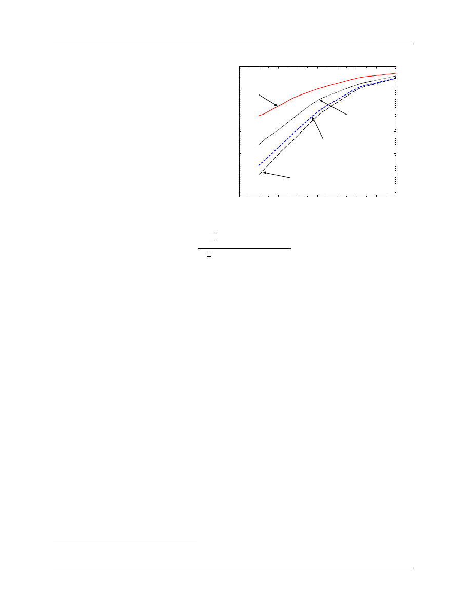
Dosimetry Fundamentals: 1996 AAPM Summer School
page 21
Figure 12: Values of P
fl
at a depth of d
ref
vs R
50
for cylindrical ion chambers. Based
on data in TG–21 from Johansson et al (1977)
and using the techniques from Rogers and
Booth (1996) to relate the various parameters.
0
2
4
6
8
10
12
14
16
R
50
/cm
0.94
0.95
0.96
0.97
0.98
0.99
1.00
electron fluence correction, P
fl
Pfl_R50
3 mm
5 mm
P
fl
at d
ref
= 0.6 R
50
− 0.1 cm
6.4 mm
7 mm
diameters of cylindrical
chambers
where:
k
R
50
=
h³
L
ρ
´
w
air
P
wall
P
fl
P
cel
i
R
50
h³
L
ρ
´
w
air
P
wall
P
fl
P
gr
P
cel
i
60
Co
,
(31)
and:
k
gr
= 1. − 0.5r
cav
G/100,
[for cylindrical chambers ]
(32)
= 1.0
[for plane-parallel chambers or at d
max
]
(33)
where
1
r
cav
is the radius of the chamber’s cavity in mm and G is the dose gradient at d
ref
(% change in
dose per mm, which can be taken as the percentage change in the ion chamber reading going from d
ref
to
d
ref
+ 0.5r
cav
2
divided by 0.5r
cav
). et al. (1996) have shown G is typically 1% or less, and hence k
gr
is within
1.6% of unity for a Farmer-like chamber. This k
gr
correction is equivalent to using the point of measurement
for cylindrical chambers recommended by the IAEA Code of Practice (1987) and the AAPM’s TG–25 (Khan
et al 1991).
With all of the above in place, it is possible to present curves of k
Q
values for plane-parallel chambers (fig.13)
and curves of k
R
50
for cylindrical chambers (fig.14). Unfortunately, these curves cannot be generalized
as easily as in the case for photon beams. For the NACP, Exradin, Attix, Holt and PTB/Roos plane-
parallel chambers, the differences between the curves are completely determined by the value of P
wall
for the
chamber in a water phantom irradiated by a
60
Co beam although recall that possible variations with P
wall
in the electron beams have not been included. For the Markus and Capintec chambers, the effect of P
fl
also
plays a significant role, especially for the lower energies. For the cylindrical chambers, several factors are at
work causing the differences seen in fig. 14. For one thing, P
fl
is strongly affected by the radius of the cavity
(see fig. 12). Also, the values of P
wall
in the
60
Co beam vary by 2.8%, or 1% going from the thin to thick
walls for the chambers with air-equivalent plastic C552 walls. For the NE2571 chamber, the central electrode
effect increases k
R
50
by 0.7% for low energy beams and 0.5% for beams above 13 MeV. The shoulder in this
curve is at the transition point in the P
cel
correction.
Another approach which would make the k
Q
curves more similar, is to define k
Q
for electron beams with
respect to an absorbed-dose calibration factor in a reference electron beam (presumably at high energies since
primary standards can be more easily developed there). In this case, instead of using a
60
Co calibration
factor in eq.(3), one uses the electron beam calibration factor:
D
Q
w
= M P
ion
k
e
Q
N
e
D,w
[Gy].
(34)
1
Eq.(32) was published as k
gr
= 1. + 0.5r
cav
G/100.
2
This was published as d
ref
− 0.5r
cav
.
6. VALUES OF K
Q
6.A. Calculation of k
Q
Values
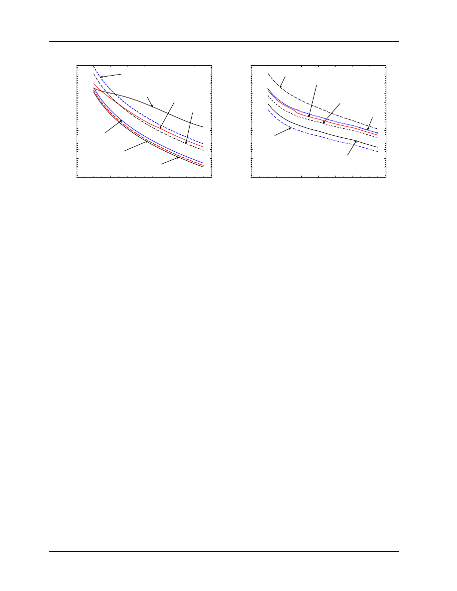
page 22
D.W.O. Rogers
0
2
4
6
8
10
12
14
16
R
50
/cm
0.84
0.85
0.86
0.87
0.88
0.89
0.90
0.91
0.92
0.93
0.94
0.95
0.96
k
Q
at d
ref
Attix
Exradin P11
Markus
NACP
PTB/Roos
kQ_pp
k
Q
vs R
50
plane−parallel chambers
Holt
at d
ref
Capintec
Figure 13:
Calculated values of k
Q
for plane-
parallel chambers used in a water phantom at d
ref
.
Chambers are assumed waterproofed as described in
table 3.
0
2
4
6
8
10
12
14
16
R
50
/cm
0.84
0.85
0.86
0.87
0.88
0.89
0.90
0.91
0.92
0.93
0.94
0.95
0.96
k
R
50
kR50
k
R
50
vs R
50
cylindrical chambers
at d
ref
PR05 C552
NE2571 gr,al electrode
NE2581 A−150
PR06 C552
PTW2333
Exradin A12
C552
Figure 14: Calculated values of k
R
50
for commonly
used cylindrical ion-chambers.
Values apply for
measurements at d
ref
in a water phantom.
The advantage of this equation is that, except for differences in P
fl
, the k
Q
or k
R
50
curves will be identical
for different detectors. To handle this in a protocol based on
60
Co absorbed-dose calibration factors requires
an extra piece of data, viz. k
el
, the ratio of N
e
D,w
to N
60
Co
D,w
. In this case, in electron beams one has:
D
Q
w
= M P
ion
k
e
Q
k
el
N
60
Co
D,w
(35)
Note that the factor k
el
is just the standard k
Q
for the beam quality chosen for the reference electron beam.
6.B.
Measurement of k
Q
Values
As mentioned above (section 3.), the ideal situation is to have k
Q
values measured using primary standards
of absorbed dose for all beam qualities of interest for all chambers which are used in the clinic. This is
impossible, especially since there are no primary standards in place for electron beams in North America.
However, on the photon side, there have been a variety of measurements reported (Shortt et al 1993; Boutillon
et al 1994; Ross et al 1994; Guerra et al 1995; Vatnitsky et al 1995), not all of which use primary standards,
and not many of which have sorted out the issues of beam quality specification (see section 5.B.). At the
present time there is a major project underway at NRC which will use primary standards at several photon
beam qualities to calibrate 3 each of 6 widely used Farmer-like cylindrical chambers and specify the beam
quality in a wide variety of manners to elucidate the best manner of doing this. Seuntjens et al (1996) are
reporting on this work at this years AAPM meeting. The already published data has shown clearly that
the calculated values of k
Q
are accurate within about 1% but there are demonstrable problems with beam
quality specification using TPR
20
10
which can lead to 0.5% problems or more. Furthermore, there are known
problems with the calculated P
wall
factors at about the 0.5% level. Within the next year, there should be a
large amount of reliable data available for photon beams, which will both allow measured data to be used
for many common detectors, or allow calculations to be done with considerable accuracy.
For electron beams, the promise of directly measured k
Q
factors is further in the future. In the meantime,
it would be very useful if further investigations were done on fluence and gradient corrections at the new
reference depth, d
ref
and on the measurement of water phantom P
wall
factors for plane-parallel chambers in
60
Co beams.
6. VALUES OF K
Q
6.B. Measurement of k
Q
Values
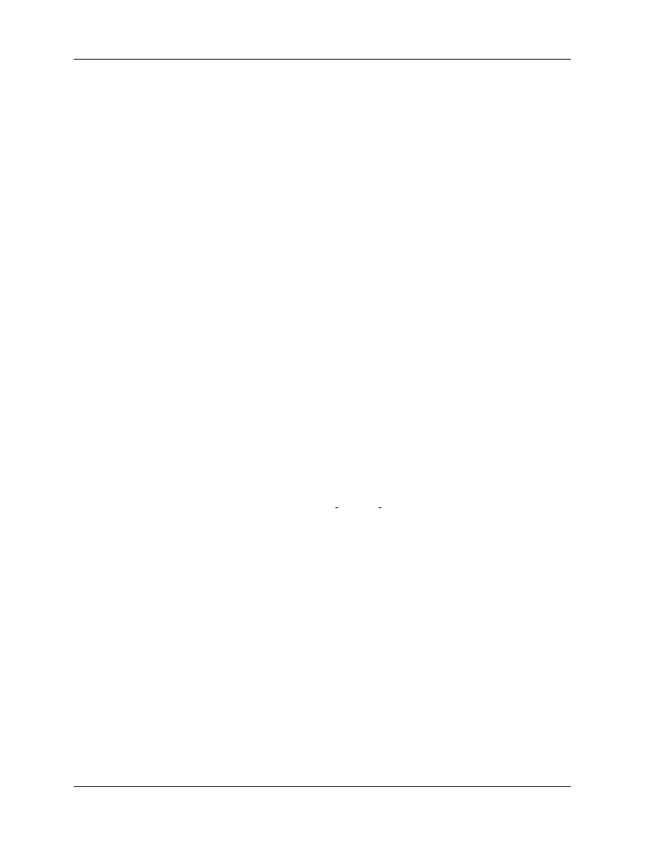
Dosimetry Fundamentals: 1996 AAPM Summer School
page 23
7.
SUMMARY
To summarize, there have been a large number of improvements in the understanding of radiation dosimetry
in the 15 years since TG–21 was developed. The most important feature is that there are now primary
standards of absorbed dose to water which can be used in accelerator photon beams and hence the ability
to make clinical measurements at the 1% level under reference conditions is, in principle, here. The new
TG-51 protocol will incorporate the use of these new standards and a variety of new approaches which should
make clinical dosimetry both simpler and more accurate. Since the assigned clinical doses will not usually
be very different from those assigned using TG–21, the transition should not be as difficult as it was when
adopting TG–21. The ADCL’s and national standards laboratories are already working on procedures for
providing the absorbed-dose calibration factors needed instead of air-kerma calibration factors. Since the
overall TG–51 protocol should be much simpler and easier to understand than the TG–21 protocol, it is
hoped that people will adopt it quickly and with little hassle.
This document does not present the TG–51 protocol, and many details which are dealt with in the protocol
have been left out. However, the current draft of the protocol is prescriptive in nature, with the intention of
making it easy to use. This chapter is actually much longer than the current draft of the protocol itself.
8.
ACKNOWLEDGMENTS
I have benefited from many thought provoking discussions with my colleagues on TG–51, viz. Peter Almond,
Peter Biggs, Bert Coursey, Will Hanson, Saiful Huq, Ravi Nath, and early on, Herb Attix. I would also
like to thank my colleagues at NRC (Carl Ross, Jan Seuntjens, Charlie Ma, Ken Shortt, Norman Klassen
and Alex Bielajew) for much work in this area plus Alan Nahum, David Burns, Pedro Andreo and Klaus
Hohlfeld for stimulating discussions over the years.
9.
REFERENCES
e-mail: dave@irs.phy.nrc.ca
WWW: http://www.irs.inms.nrc.ca/inms/irs/papers/irs www/irs www.html
AAPM TG–21 (1983). A protocol for the determination of absorbed dose from high-energy photon and
electron beams. Med. Phys. 10: 741 – 771.
AAPM TG–21 (1984). Erratum: A protocol for the determination of absorbed dose from high-energy
photon and electron beams. Med. Phys. 11: 213.
Almond, P. R., Attix, F. H., Goetsch, S., Humphries, L. J., Kubo, H., Nath, R., and Rogers, D. W. O.
(1994). The calibration and use of plane-parallel ionization chambers for dosimetry of electron beams:
An extension of the 1983 AAPM protocol, Report of AAPM Radiation Therapy Committee Task
Group 39. Med. Phys. 21: 1251 – 1260.
Andreo, P. (1992). Absorbed dose beam quality factors for the dosimetry of high-energy photon beams.
Phys. Med. Biol. 37: 2189 – 2211.
Andreo, P. (1993). The status of high-energy photon and electron beam dosimetry five years after the
implementation of the IAEA code of practice in the Nordic countries. Acta Oncologica 32: 483 – 500.
Andreo, P. and Brahme, A. (1986). Stopping-power data for high-energy photon beams. Phys. Med.
Biol. 31: 839 – 858.

page 24
D.W.O. Rogers
Andreo, P., Brahme, A., Nahum, A. E., and Mattsson, O. (1989). Influence of energy and angular spread
on stopping-power ratios for electron beams. Phys. Med. Biol. 34: 751 – 768.
Andreo, P. and Fransson, A. (1989). Stopping-power ratios and their uncertainties for clinical electron
beam dosimetry. Phys. Med. Biol. 34: 1847 – 1861.
Attix, F. H. (1986). Introduction to Radiological Physics and Radiation Dosimetry. New York: Wiley.
Berger, M. J. and Seltzer, S. M. (1983). Stopping power and ranges of electrons and positrons. NBS
Report NBSIR 82-2550-A (second edition).
Bielajew, A. F. and Rogers, D. W. O. (1992). Implications of new correction factors on primary air kerma
standards in
60
Co beams. Phys. Med. Biol. 37: 1283 – 1291.
Boag, J. W. (1987). Ionization Chambers. In K. R. Kase, B. E. Bj¨arngard, and F. H. Attix (Eds.), The
Dosimetry of Ionizing Radiation,Vol II, pp. 169 – 243. Academic Press.
Boutillon, M., Coursey, B. M., Hohlfeld, K., Owen, B., and Rogers, D. W. O. (1994). Comparison of
primary water absorbed dose standards. IAEA–SM–330/48, in Proceedings of Symposium on Mea-
surement Assurance in Dosimetry, (IAEA, Vienna): 95 – 111.
Boutillon, M. and Perroche-Roux, A. M. (1987). Re-evaluation of the W value for electrons in dry air.
Phys. Med. Biol. 32: 213 – 219.
Cunningham, J. R. and Schulz, R. J. (1984). On the selection of stopping-power and mass-energy absorp-
tion coefficient ratios for high energy x-ray dosimetry. Med. Phys. 11: 618 – 623.
Cunningham, J. R. and Sontag, M. R. (1980). Displacement Corrections Used in Absorbed Dose Deter-
minations. Med. Phys. 7: 672 – 676.
Ding, G. X. and Rogers, D. W. O. (1995). Energy spectra, angular spread, and dose distributions of
electron beams from various accelerators used in radiotherapy. National Research Council of Canada
Report PIRS-0439:
(see http://www.irs.inms.nrc.ca/inms/irs/papers/PIRS439/pirs439.html).
Ding, G. X., Rogers, D. W. O., Cygler, J., and Mackie, T. R. (1997). . Med. Phys.
Ding, G. X., Rogers, D. W. O., and Mackie, T. R. (1995). Calculation of stopping-power ratios using
realistic clinical electron beams. Med. Phys. 22: 489 – 501.
Ding, G. X., Rogers, D. W. O., and Mackie, T. R. (1996). . Med. Phys. 23: 361 – 376.
Domen, S. R. (1994). A sealed water calorimeter for measuring absorbed dose. J of Res of NIST 99: 121
– 141.
Domen, S. R. and Lamperti, P. J. (1974). A Heat-Loss-Compensated Calorimeter: Theory, Design and
Performance. J. of Res. of NBS 78A: 595 – 610.
et al., B. (1996). . Med. Phys.
Feist, H. (1982). Determination of the absorbed dose to water for high-energy photons and electrons by
total absorption of electrons in ferrous sulphate solution. Phys. Med. Biol. 27: 1435 – 1447.
Gillin, M. T., Kline, R. W., Niroomand-Rad, A., and Grimm, D. F. (1985). The effect of thickness of the
waterproofing sheath on the calibration of photon and electron beams. Med. Phys. 12: 234 – 236.
Guerra, A. S., Laitano, R. F., and Pimpinella, M. (1995). Experimental determination of the beam quality
dependence factors, k
Q
, for ionization chambers used in photon and electron dosimetry. Phys. Med.
Biol. 40: 1177 – 1190.
Hanson, W. F. and Tinoco, J. A. D. (1985). Effects of plastic protective caps on the calibration of therapy
beams in water. Med. Phys. 12: 243 – 248.
Hohlfeld, K. (1988). The standard DIN 6800: Procedures for absorbed dose determination in radiology
by the ionization method. in Proc. of 1987 Symposium on Dosimetry in Radiotherapy (IAEA, Vienna)
Vol 1: 13 – 24.
Hunt, M. A., Kutcher, G. J., and Buffa, A. (1988). Electron backscatter correction for parallel-plate
chambers. Med. Phys. 15: 96 – 103.

Dosimetry Fundamentals: 1996 AAPM Summer School
page 25
IAEA (1987). Absorbed Dose Determination in Photon and Electron Beams; An International Code of
Practice, Volume 277 of Technical Report Series. Vienna: IAEA.
ICRU (1984a). Radiation Dosimetry: Electron beams with energies between 1 and 50 MeV. ICRU Re-
port 35, ICRU, Washington D.C.
ICRU (1984b). Stopping powers for electrons and positrons. ICRU Report 37, ICRU, Bethesda, MD.
ICRU (1990). ICRU Report Committee Activities. in ICRU News(ICRU, Bethesda MD), June: 20.
Johansson, K. A., Mattsson, L. O., Lindborg, L., and Svensson, H. (1977). Absorbed-dose determination
with ionization chambers in electron and photon beams having energies between 1 and 50 MeV. IAEA
Symposium Proceedings, (Vienna) IAEA-SM-222/35: 243 – 270.
Khan, F. M. (1991). Replacement correction (P
repl
) for ion chamber dosimetry. Med. Phys. 18: 1244 –
1246.
Khan, F. M., Doppke, K. P., Hogstrom, K. R., Kutcher, G. J., Nath, R., Prasad, S. C., Purdy, J. A.,
Rozenfeld, M., and Werner, B. L. (1991). Clinical electron-beam dosimetry: Report of AAPM Radi-
ation Therapy Committee Task Group 25. Med. Phys. 18: 73 – 109.
Klevenhagen, S. C. (1991). Implications of electron backscatter for electron dosimetry. Phys. Med. Biol. 36:
1013 – 1018.
Kosunen, A. and Rogers, D. W. O. (1993). Beam Quality Specification for Photon Beam Dosimetry. Med.
Phys. 20: 1181 – 1188.
LaRiviere, P. D. (1989). The quality of high-energy X-ray beams. Br. J. of Radiology 62: 473 – 481.
Lempert, G. D., Nath, R., and Schulz, R. J. (1983). Fraction of ionization from electrons arising in the
wall of an ionization chamber. Med. Phys. 10: 1 – 3.
Li, X. A. and Rogers, D. W. O. (1994). Reducing Electron Contamination for Photon-Beam-Quality
Specification. Med. Phys. 21: 791 – 798.
Ma, C.-M. and Nahum, A. E. (1993). Effect of size and composition of central electrode on the response
of cylindrical ionisation chambers in high-energy photon and electron beams. Phys. Med. Biol. 38: 267
– 290.
Ma, C.-M. and Rogers, D. W. O. (1995). Monte Carlo calculated wall correction factors for plane-parallel
chambers in high-energy electron beams. Med. Phys. (abstract) 22: 672.
Mattsson, L. O., Johansson, K. A., and Svensson, H. (1981). Calibration and use of plane-parallel
ionization chambers for the determination of absorbed dose in electron beams. Acta Radiol. Ther.
Phys. Biol. 20: 385 – 399.
Mijnheer, B. J. and Williams, J. R. (1985). Comments on dry air or humid air values for physical
parameters used in the AAPM protocol for photon and electron dosimetry. Med. Phys. 12: 656 – 658.
NACP (1980). Procedures in external beam radiation therapy dosimetry with photon and electron beams
with maximum energies between 1 and 50 MeV. Acta Radiol. Oncol. 19: 55 – 79.
Nahum, A. E. (1978). Water/Air Stopping-Power Ratios for Megavoltage Photon and Electron Beams.
Phys. Med. Biol. 23: 24 – 38.
Nahum, A. E. (1988). Extension of the Spencer-Attix Cavity Theory to the 3-Media Situation for Electron
Beams. in “Dosimetry in Radiotherapy”, (IAEA, Vienna) Vol 1: 87 – 115.
Nahum, A. E. (1994). Perturbation Effects in Dosimetry. Technical Report ICR-PHYS-1/94, Joint Dept
of Physics, The Royal Marsden Hospital, Sutton, Surrey, SM2 5PT, UK.
Nath, R. and Huq, M. S. (1995). Advances in Radiation Dosimetry. In A. R. Smith (Ed.), Radiation
Therapy Physics, pp. 401 – 448. Springer-Verlag.
Pruitt, J. S., Domen, S. R., and Loevinger, R. (1981). The Graphite Calorimeter as a Standard of
Absorbed Dose for
60
Co Gamma Radiation. J of Res. of NBS 86: 495 – 502.
Rikner, G. (1985). Characteristics of a p-Si detector in high energy electron fields. Acta Rad. Oncol. 24:
71 – 74.

page 26
D.W.O. Rogers
Rogers, D. W. O. (1992a). Calibration of Parallel–Plate Ion Chambers: Resolution of Several Problems
by Using Monte Carlo Calculations. Med. Phys. 19: 889 – 899.
Rogers, D. W. O. (1992b). New Dosimetry Standards. In J. Purdy (Ed.), Advances in Radiation Oncology
Physics, Medical Physics Monograph 19, pp. 90 – 110. AAPM, New York.
Rogers, D. W. O. (1992c). The advantages of absorbed-dose calibration factors. Med. Phys. 19: 1227 –
1239.
Rogers, D. W. O. (1992d). Fundamentals of High Energy X-ray and Electron Dosimetry Protocols. In
J. Purdy (Ed.), Advances in Radiation Oncology Physics, Medical Physics Monograph 19, pp. 181 –
223. AAPM, New York.
Rogers, D. W. O. (1997 (submitted)). . Med. Phys.
Rogers, D. W. O. and Bielajew, A. F. (1986). Differences in Electron Depth Dose Curves Calculated with
EGS and ETRAN and Improved Energy Range Relationships. Med. Phys. 13: 687 – 694.
Rogers, D. W. O. and Booth, A. (1996). PROT: A General Purpose Utility for Calculating Quantities
related to Dosimetry Protocols. Technical Report PIRS–529, NRC Canada, Ottawa, K1A 0R6.
Rogers, D. W. O. and Ross, C. K. (1988). The Role of Humidity and Other Correction Factors in the
AAPM TG–21 Dosimetry Protocol. Med. Phys. 15: 40 – 48.
Rogers, D. W. O., Ross, C. K., Shortt, K. R., and Bielajew, A. F. (1986). Comments on the
60
Co
Graphite/Air Stopping-Power Ratio used in the AAPM Protocol. Med. Phys. 13: 964 – 965.
Rogers, D. W. O., Ross, C. K., Shortt, K. R., Klassen, N. V., and Bielajew, A. F. (1994). Towards a
Dosimetry System Based on Absorbed-Dose Standards. IAEA–SM–330/9 in Proc. of Symp. on Meas.
Assurance in Dosimetry, (IAEA, Vienna): 565 – 580.
Ross, C. K. and Klassen, N. V. (1996). Water calorimetry for radiation dosimetry. Phys. Med. Biol. 41:
1 – 29.
Ross, C. K., Klassen, N. V., Shortt, K. R., and Smith, G. D. (1989). A direct comparison of water
calorimetry and Fricke dosimetry. Phys. Med. Biol. 34: 23 – 42.
Ross, C. K., Klassen, N. V., and Smith, G. D. (1984). The Effect of Various Dissolved Gases on the Heat
Defect of Water. Med. Phys. 11: 653 – 658.
Ross, C. K. and Shortt, K. R. (1992). The effect of waterproofing sleeves on ionization chamber response.
Phys. Med. Biol. 37: 1403 – 1411.
Ross, C. K., Shortt, K. R., Rogers, D. W. O., and Delaunay, F. (1994). A Test of TPR
20
10
as a Beam
Quality Specifier for High-Energy Photon Beams. IAEA–SM–330/10, in Proceedings of Symposium on
Measurement Assurance in Dosimetry, (IAEA, Vienna): 309 – 321.
Schulz, R. J., Almond, P. R., Kutcher, G., Loevinger, R., Nath, R., Rogers, D. W. O., Suntharalingham,
N., Wright, K. A., and Khan, F. (1986). Clarification of the AAPM Task Group 21 Protocol. Med.
Phys. 13: 755 – 759.
Seuntjens, J., Van der Plaetsen, A., Van Laere, K., and Thierens, H. (1993). Study of correction factors
and the relative heat defect of a water calorimetric determination of absorbed dose to water in high
energy photon beams. IAEA-SM-330/6 in: Measurement Assurance in Dosimetry. Proceedings of a
Symposium, Vienna 24–27 May, 1993 (Vienna: IAEA): 45 – 59.
Seuntjens, J. P., Shortt, K. R., Ross, C. K., Ma, C. M., and Rogers, D. W. O. (1996). Measurement of
beam quality factors k
Q
for cylindrical ionization chambers in high energy photon beams. Med. Phys.
(abstract) 23: 1071.
Shiragai, A. (1978). A Proposal Concerning the Absorbed Dose Conversion Factor. Phys. Med. Biol. 23:
245 – 252.
Shiragai, A. (1979). Effective Mass Stopping Power Ratio in Photon Dosimetry. Phys. Med. Biol. 24: 452
– 454.

Dosimetry Fundamentals: 1996 AAPM Summer School
page 27
Shortt, K. R., Ross, C. K., Schneider, M., Hohlfeld, K., Roos, M., and Perroche, A.-M. (1993). A
Comparison of Absorbed Dose Standards for High Energy X-rays. Phys. Med. Biol. 38: 1937 – 1955.
Spencer, L. V. and Attix, F. H. (1955). A theory of cavity ionization. Radiat. Res. 3: 239 – 254.
Van der Plaetsen, A., Seuntjens, J., Thierens, H., and Vynckier, S. (1994). Verification of absorbed doses
determined with thimble and parallel-plate ionization chambers in clinical electron beams using ferrous
sulphate dosimetry. Med. Phys. 21: 37 – 44.
Vatnitsky, S. M., Siebers, J. V., and Miller, D. W. (1995). Calorimetric determination of the absorbed
dose–to–water beam quality correction factor k
Q
for high–energy photon beams. Med. Phys. 22: 1749
– 1752.
Weinhous, M. S. and Meli, J. A. (1984). Determining P
ion
, the correction factor for recombination loses
in an ionization chamber. Med. Phys. 11: 846 – 849.
Wu, A., Kalend, A. M., Zwicker, R. D., and Sternick, E. S. (1984). Comments on the method of energy
determination for electron beam in the TG–21 protocol. Med. Phys. 11: 871 – 872.
Wyszukiwarka
Podobne podstrony:
Fundamentals of radiation dosimetry and radiological physics
Comparative study based on exergy analysis of solar air heater collector using thermal energy storag
ebook occult The Psychedelic Experience A manual based on the Tibetan Book of the Dead
Network Virus Propagation Model Based on Effects of Removing Time and User Vigilance
Phylogeny of the enterobacteriaceae based on genes encoding elongation factor Tu
Implementation of a Mu;ti level Inverter Based on Selective Harmonic Elimination and Zig Zag Connect
Munster B , Prinssen W Acoustic Enhancement Systems – Design Approach And Evaluation Of Room Acoust
PWR A Full Compensating System for General Loads, Based on a Combination of Thyristor Binary Compens
Kim Control of auditory distance perception based on the auditory parallax model
Exergetic efficiency of high temperature lift chemical heat pump (CHP) based on CaO CO2 and CaO H2O
Roman, Małgorzata; Niska, Monika Development of Kubłowo Palaeolake in Central Poland During Eemian
Models for drying kinetics based on drying curves of slabs
Fundamentals of Polymer Chemist Nieznany
Effect of Kinesio taping on muscle strength in athletes
53 755 765 Effect of Microstructural Homogenity on Mechanical and Thermal Fatique
69 991 1002 Formation of Alumina Layer on Aluminium Containing Steels for Prevention of
więcej podobnych podstron