AITES
ITA
Towards an
improved use
of underground
Space
In Consultative Status, Category II with the
United Nations Economic and Social Council
http://www.ita-aites.org
ASSOCIATION
INTERNATIONALE DES TRAVAUX
EN SOUTERRAIN
INTERNATIONAL
TUNNELLING
ASSOCIATION
Ideas on tunnel stability
CONVENTIONAL TUNNELLING
Title
Topic
published
Abstract:
-
Résumé:
-
Remarks:
It is difficult to discuss "Ideas on Tunnel Stability" without their immediate association with the construction
methods that apply such ideas, or that were at the origin of such ideas. During tunnelling operations,
construction methods always need to be adapted to a natural environment which never is exactly as it was
imagined during the design process. Therefore a good s u p p o rting method has to fit the changing anatomy
and physiology of the rock mass, and should be evaluated for its adaptability to the laws and whims of Nature,
rather than for its theoretical qualities.
The following paper discusses tunnels driven with conventional methods and not those made with a shield or
tunnel-boring machine.
in "Tribune",
Working Group:
WG 19 - "Conventional Tunnelling"
Author
ITA WG Conventional Tunnelling, P. Duffaut, J. Piraud
Open Session, Seminar, Workshop:
-
Others:
Paper
by ITA - AITES, www.ita-aites.org
Nr. 22, pp. 32 - 36, Year 2002
Secretariat : ITA-AITES c/o EPFL - Bât. GC – CH-1015 Lausanne - Switzerland
Fax : +41 21 693 41 53 - Tel. : +41 21 693 23 10 - e-mail : secretariat@ita-aites.org - www.ita-aites.org

It is difficult to discuss "Ideas on Tunnel Stability"
without their immediate association with the construc-
tion methods that apply such ideas, or that were at the
origin of such ideas. During tunnelling operations,
construction methods always need to be adapted to a
natural environment which never is exactly as it was
imagined during the design process. Therefore a good
s u p p o rting method has to fit the changing anatomy
and physiology of the rock mass, and should be eva-
luated for its adaptability to the laws and whims of
Nature, rather than for its theoretical qualities.
The following paper discusses tunnels driven with
conventional methods and not those made with a
shield or tunnel-boring machine.
THE PRINCIPLE OF SELF-SUPPORT
In the beginning, the self-support of holes and cavities
went without saying. This basic principle, also named
arch effect or arching, gave stable caverns to the pre-
historic men, even inside low strength rocks provided
they harbour not too many joints.
Another type of self-supporting stru c t u res are the
c a v e rns dug below a thick bed, like room and pillar
mining, which had been widely used for a long time at
the border of the limestone plateaux.
Early architects also used self-support in order to build
vaults, for bridges as well as for churches or base-
ments. These vaults are stable even without any
cement, provided that the building blocks are well fit-
ted. Such arches face the gravity forces by progressive
stressing of their elements. Above ground such arches
need heavy buttresses to provide for lateral abut-
ments; below the surface, however, full 3D abutments
are provided by Nature for free.
What is true for built arches is also true for tunnels and
caverns, whether natural or man-made:
If the rock is strong enough to bear the tangential
stress along the perimeter (approx.: R
c
> 3
γH around a
circular hole), and if there are no ill-oriented joint sur-
faces, the hole will stand without any support. Natural
caves as wide as 50 m are not uncommon, and the lar-
gest known to date spans almost 400 m (Good Luck
Cave, Sarawak, Malaysia).
When the strength of the rock is exceeded along the
perimeter of the hole, and provided that the rock mass
is rather homogeneous, a plastic ring appears around
t he hole, accommod ati ng t he excess of stre s s .
Excessive damage to the rock mass by plastic strain
may be prevented by a minimal skin support such as a
thin shotcrete cover.
F i n a l l y, if the rock mass is too strongly fractured or
even soil like, self-support is no longer viable and the
only answer is to strengthen the rock mass as a whole,
through extensive grouting or rock bolting.
THE TIME OF PASSIVE SUPPORT
During the 19th and the first part of the 20th Century,
before the time of shotcrete and rock bolts, tunnel men
had no better way than dividing the full tunnel section
into smaller ones, bored one after the other, each of
them heavily timbered. It should not come as a surpri-
se that the tunnel construction resulted at that time in
many "national" methods, known then as English,
Belgian, French, German, Austrian and Italian tunnel-
ling methods (see for example Duffaut and Piraud,
1975).
In those methods, the place of self-support was re s-
tricted to so-called "good ground", and elsewhere to a
few tiny spaces between timber pieces. This timber
s u p p o rt was temporary and had to be replaced by
thick vaults of masonry or brickwork, likely to stand for
many years. The major fault of such stru c t u res was
that their contact with the surrounding rock mass was
both late (it took weeks or months before the vault
could be constructed) and discontinuous (a smooth
vault cannot fit against a rough rock walls). This delay
provided time and space for weathering and loosening
of the rock mass, which, little by little, will impose
i n c reasing loads upon the vault and justify its thick-
ness a posteriori.
After the Word War I, two major innovations appeared:
As temporary support, steel ribs replaced timber, allo-
wing wider spans to be supported; this method, stan-
d a rdised by Te rzaghi (1949), later became known as
AMSS, American Method of Steel Support;
As definitive lining, cast-in-place concrete favourably
replaced masonry, providing an intimate contact bet-
ween vault and rock mass, even if somewhat late.
Both innovations introduced a type of industrialisation
in tunnelling, allowing faster boring with less manpo-
wer. But this progress hid two fundamental drawbacks
of the passive support: an excessively long operational
delay and a discontinuous contact between the sup-
p o rt and the surrounding rock mass before concre t e
casting. As a consequence the final lining was desi-
gned and justified as a bearing structure, submitted to
i l l - m a s t e red or unknown external loads; hence the
s t ructural calculations by the well known "springs
method", based on rather rough hypotheses, easily
adjustable to any presupposed results...
These drawbacks, intrinsic to passive supports, were
tolerable for most shallow tunnels, as well as for some
I D E A S O N T U N N E L S T A B I L I T Y
Pierre DUFFAUT, Consulting Engineer, Paris & Jean PIRAUD, ANTEA, Orléans, France
TRIBUNE n°22 - ITA-AITES - June 2002
32
deep tunnels in hard rocks like the first Gotthard rail-
way tunnel in 1875. However, they became prohibitive
when the Simplon tunnel, about 1900, had to cro s s
c rushed rock at great depth. No vault, whatever its
thickness, could withstand the thrust of 2000 m of
mountain. One had to understand that the only way
was "to let the rock mass come", as coal miners used
to do: being accustomed to the behaviour of rocks at
greet depth, they had learned how to tame soft or cru-
shed rocks like coal.
Such alpine experience was the basis for the Swiss
engineers Maillart and Andreae, who had the intuition
of the shotcrete efficiency some decades in advance:
Maillart, 1922: "masonry must tightly fit the rock-mass
contour", Andreae, 1949: "a light support, but quickly
installed, is the most efficient mean against ro c k
thrust".
As Rziha wrote in his Handbook for Tunnelling as early
as 1874, "the true art of the engineer is to prevent the
build-up of rock thrust instead of overcoming it after it
has built up". This fundamental target has been forgot -
ten during almost a century, through the lack of techni-
cal means likely to achieve it.
THE INVENTION OF NATM
Some years later, around 1960, the same acknowled-
gements as made in Switzerland led the Austrian engi-
neer von Rabcewicz to
p ut int o practic e the
pr in ci pl es qu ote d
above. He implemented
t wo ne wly a vaila ble
technologies, i.e. ro c k
b o lts bor rowed fro m
coal miners and shot-
c ret e
c om ing
f ro m
America, where such
material was used for a
lo ng tim e to re p a i r
da mage d str u c t u re s .
Th e targe t of the
meth od was c lea rl y
posted: "help the ro c k
mass to support itself",
instead of striving to support the rock thrust with the
help of a lot of heavy members
Austrian engineers pointed out that the cross section
shape and the excavation method were crucial in order
to avoid, as far as possible, any damage to the sur-
rounding ground. They understood that they had to
m e a s u re accurately the reactions of the ground with
time, just as did for a long time the dam engineers.
So began the "new" Austrian Tunnelling Method,
N ATM, which was to become the spearhead of the
" S a l z b u rg Club", under the aegis of Prof. Leopold
M ü l l e r. After successful applications to exceptional
works such as the Frankfurt metro or the Wa l d e c k
u n d e rg round power station, in central Germ a n y, the
method appealed to some interested French engi-
neers, among them Claude Louis. He worked with the
authors to make French contractors aware of the
major progress brought by NATM, and of the potential
savings brought to owners; he showed that in some
cases this new method was the only technical answer
(cf. Louis, 1972).
Some relevant images were proposed at that time to
illustrate the core of the message: the new technolo-
gies, shotcrete and rockbolts, could be compared to
glue and nails as used in woodwork; the four main
points of NATM may be associated with simple formu-
las:
Excavating with care, thanks to a rounded cross sec-
tion and a smooth blasting, may be compared to care-
fully dismantling the rock mass (instead of blasting it at
full strength);
Protecting the excavated rock surface with a shotcrete
skin, equals dressing and bandaging a wound;
Rock bolting equals reinforcing the ground, as usually
done in reinforced concrete;
Monitoring the ground behaviour implies relying on
measurements rather than on calculations.
The complex formed by rock mass + rockbolts + shot-
c rete may be com-
pared to a complex
of re i n f o rced eart h ,
i.e. a granular soil
mass + me tal li c
st ri ps + faci ng
pane ls . I n both
c as e s, t he m ain
mechanical role is
played by the re i n-
f o rc e d
gro u n d
mass ;
sh otc re t e
a ct s like a s kin
o n l y, whose role is
vital for pro t e c t i n g
the freshly exposed
rock mass, but subordinate from the mechanical point
of view.
As a conclusion, NATM expressed in the art of tunnel-
ling the paradigm shifts that dominated geotechnics
along the second part of the 20th Century: to improve
the pro p e rties of in-situ ground instead of trying to
make up for its weakness through costly art i f i c i a l
s t ru c t u res. Plenty of ground is available around tun-
nels, providing free 3D abutments; to obtain the best
of it, one only needs to inject intelligence. The English
w o rd "support" (like the French word "soutènement")
is misleading: the action of shotcrete and rockbolts is
I D E A S O N T U N N E L S T A B I L I T Y
TRIBUNE n°22 - ITA-AITES - June 2002
33
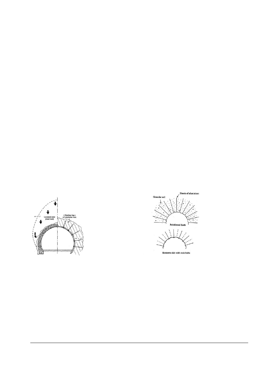
Comparison between a thick, passi-
ve support (on the left) and the "bea -
ring ring of re i n f o rced rock" of the
NATM (from Louis, 1972).
Analogy between a tunnel support with
s h o t c rete and rock bolts (below) and a
vault of re i n f o rced earth (above); experi-
mental set-up studied by Behnia, 1973.
to maintain, retain, or contain the ground, but never to
sustain or support it (Duffaut, 1994).
The main re s e rvation, though, is that this method
absolutely requires a great rapidity of implementation,
a rigorous work organisation, and real-time monitoring.
The lack of any one of these three conditions may
create a dangerous situation; this is why it can only be
operated with highly qualified and experienced staff at
all levels.
During the 1970s and 1980s hundreds of kilometres of
N ATM tunnels were bored successfully, the more in
Austria, Germ a n y, Switzerland, Italy, and Japan.
Obviously, some failures have been reported. The most
famous examples are in Munich (Germ a n y, 27th
Sep.1994) and below the Heathrow airport (UK, 21st
Oct. 1994). The first case was associated with an
unexpected local deepening of the alluvial gravel down
to the tunnel crown; the second with a too optimistic
design for three parallel tunnels, a method proved valid
inside the chalk of the Channel tunnel but no longer so
in the London Clay. A French advertising slogan sug-
gests that "one glass of wine is harmless for car dri-
vers, but the damage begins with the second": this
ought to be the same rule for tunnels in soils.
THE TRIUMPH OF NATM
During the 1970s and 1980s, the concept of a "bearing
ring of reinforced rock" became the essential feature in
the world for conventional tunnelling. Still, its applica-
tions varied depending upon the thickness of the over-
burden:
For deep tunnels, the major concern is to accompany
the elastic or elasto-plastic stress release of the rock,
preventing it from becoming disorganised, or, in milita-
ry terms, by favouring its ordered retreat rather than a
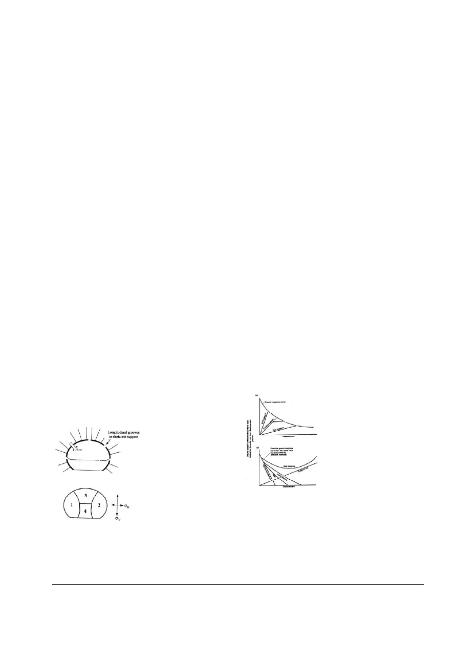
rout. If the expected convergence is such that the
s h o t c rete shell might break, it is necessary to cre a t e
longitudinal grooves that will close once the rock mass
has c onve rg ed. Such
g rooves delimit indepen-
den t pa rt s of the vau lt
that are literally suspen-
ded from the rock mass
by means of rock bolts, in
t he same man ner as a
"Berliner" wall is attached
to the soil mass by pre s-
t
res sed a nc h ors. Th e
Ta u e r n ,
K ar aw ank en,
Arlberg and Inntal tunnels
number among the most
d i ff icult tun ne ls dr iv en
t h rough the Alps in this
manner.
For shallow tunnels, commonly driven through soil or
soft rocks, any deformation must be prevented in
order to avoid irreversible shearing in the ground and
limit surface settlements. In the 1980s, Austrian engi-
neers had the idea of replacing the top heading with
two ogival sidewall drifts, whose shape is much better
suited to the low horizontal stress that prevails near
the ground surface. The subways of Vienna and most
G e rman towns, as well as 150km of German high-
speed railway tunnels, were constructed in this man-
n e r, if necessary after grouting or drawing down the
g roundwater level. However, in order to avoid having
to pay the Austrians an export premium, the German
engineers renamed the method as "Spritz betonbau-
weise" (literally: sprayed concrete lining method).
Outside the Germanic world, the main tunnellers, i.e.
Italians and Japanese, adopted NATM practices in the
1970s and China did so in the 1980s. Since then,
th e se co un tr ie s ha ve us ed just two tu nne llin g
methods: either TBM, or NATM.
American and English engineers, however, ignored this
"continental" invention for a long time. England disco-
vered it belatedly during work for the Channel Tunnel,
and brilliantly applied it to excavating an enorm o u s
c a v e rn for the tunnels crossover at 40 m below the
seafloor. The major British engineering firms have tried
to rename NATM as SCL ("Sprayed Concrete Lining"),
a name that places undue emphasis on the re l a t i v e l y
minor role played by shotcrete.
THE FRENCH EXCEPTION
NATM arrived in France at the beginning of the 1970s
and was successfully used in soft rocks under low
o v e r b u rden, in particular for highway tunnels at Nice,
for the railway tunnel at Grigny near Paris and for
many projects of EDF (the
French Electricity Board). As
had happened in Germ a n y,
the French tried to gallicise
the name of NATM with the
s h o rt-lived French acro n y m
PTSS (for Participation du
terrain stabilisé au soutène-
ment), introduced in 1982 in
t h e hand b ook fo r
Government contracts.
During the same period,
F rench engineers gave an
i n t e resting contribution to
the tunnel design by deve-
loping the "Convergence-confinement" method under
the guidance of Marc Panet. This theory uses mathe-
matical terms for expressing the behaviour of the ring
of rock around a tunnel: the stresses imposed on the
s u p p o rt gene rally de crease wit h the conti nuing
convergence of this ring (Panet, 1995). This is the clas-
I D E A S O N T U N N E L S T A B I L I T Y
TRIBUNE n°22 - ITA-AITES - June 2002
34
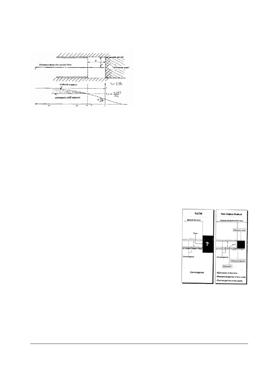
Var ia n t s o f t h e NAT M : a b o v e ,
d ee p tu nne l w it h l o ng i tu di na l
g ro o v e s , b e l o w, shallow tunnel
with ogival sidewall drifts.
Characteristic curves of sup-
p o rt a n d gr ou n d re s p o n s e
(from Hudson, 1993)
sic "Support supply and support demand" compari-
son. Even though the method uses 2D calculations, it
implicitly considers the 3D role played by the tunnel
face, using the "unloading factor".
In practice, however, many French engineers conti-
nued to ignore the specifics of NATM, banned the
term from the French vocabulary, and continued the
application of the good old "passive support" sys-
tem, which is more lucrative in poor ground condi-
tions when the arches are paid by weight (!). This
c o n f o rmism contrasted with the rapid adoption of
TBM and shields by the French contractors after
1985.
In fact, the senior author was one of the few in the
French Tunnelling Society (AFTES) who persisted not
only in defending NATM, but also in calling it by its
p roper name and in reminding all and sundry of its
successes. At the same time, a bizarre controversy
arose in some scientific circles concerning the exact
definition and even the existence of this method (cf.
Kovari, 1994). It is true that its many application
variants have disconcerted some theoreticians, but in
practice a NATM tunnel is immediately recognised by
some common and clear characteristics:
Confidence in self-support and rounded shapes;
Immediate use of shotcrete and rock bolts;
Rapid closure of the section and careful monitoring of
deformation.
C u r i o u s l y, the French engineers have perfectly inte-
gr a te d NAT M pr ac tic es in the ir in t er n a t i o n a l
contracts. A striking example is the CERN cavern s
that are being completed near Geneva by a joint
EDF-Knight Piesold engineering venture. A distinctive
characteristic of these openings with a span of
almost 20 m is that, for the first time, the shotcre t e
shell is ignored as a structural element in the stability
calculations. This is not to say that its role is negli-
gible; on the contrary, thanks to this shell the sur-
rounding rock does not loosen and retains its original
p ro p e rties, or even improved ones thanks to ro c k
bolting (cf. Laigle et al., 2001).
EMERGENCE OF THE NEW ITALIAN METHOD
In soft or weak ground, or under conditions where the
rock strength cannot withstand the overburd e n ,
experience had taught that not only the tunnel walls
but also the face have to be supported. This can be
done in various ways (cf. Pelizza et al., 1993):
By keeping a stabilising mass of ground (short bench)
in the middle of the face;
By spraying concrete on the tunnel face;
By re i n f o rcing the face with horizontal fibre g l a s s
bolts;
By forepoling with steel bars or pipes ("umbre l l a " )
along the future tunnel walls;
By creating resistant arches along these future walls,
either by mechanical pre-cutting and concrete "pre -
vaults"(Perforex method), or by jet grouting.
All these pre-support methods have the same objec-
tive: avoid collapse of the tunnel face, which would
render useless all further wall support. The above
mentioned techniques developed in many countries
during the 1980s, but without a global understanding
of the mechanisms involved; in fact, practice largely
p receded theory. In France, the major step was the
Galaure TGV tunnel south of Lyons, which was suc-
cessfully excavated by a JV led by Bouygues in
1991-93; notwithstanding an exceptional cross sec-
tion of 150 m
2
, it was dug in full section, after mecha-
nical pre-cutting and face re i n f o rcement by 18-m
horizontal rock bolts.
Although the pre-
v aul ts met ho d
was patented in
France, the deve-
lopment and sys -
t e m a t i c
ap pli cat io n o f
p r e - s u p p o r t
m e thods ca me
f rom Italy, where
much of the tun-
nelling ground is
com p os ed o f
w e ak o r so ft
ro cks , ofte n
s t r ong ly f o lde d
an d fa ul te d.
P i e t ro L una rd i
had the merit of
unifying these techniques by proposing a tunnel-sta-
bility theory that is based entirely on the equilibrium
conditions of the "advance core". This theory favours
an axial-symmetric, rather than transverse, stability
a p p roach; the decisive parameter is the axial defor-
mation ("extrusion") of the advance core, which pre-
I D E A S O N T U N N E L S T A B I L I T Y
TRIBUNE n°22 - ITA-AITES - June 2002
35
Variation of the radial displacement u for supports of various stiff-
ness (from Panet, 1973).
Comparative analysis of the deform a t i o n
r es po n s e o f a ro ck ma s s , u si n g th e
Austrian and Italian methods (from Lunardi,
2000)
cedes and causes the convergence of the tunnel walls.
This theory is known as ADECO-RS (Analisi delle
d e f o rmazioni controllate nelle rocce e nei suoli). Like
NATM some 30 years before, it proposes a true "cultu-
ral" revolution in that:
Everything revolves at the face: a tunnel with an uns-
table face will collapse, even though its walls may be
supported;
The next step is to close the ring as rapidly as pos-
sible: the cross section must not be divided, even and
especially in poor ground conditions!
Where NATM seeks to create a bearing ring of reinfor-
ced rock around the excavated section, the New
Italian Method seeks to create good ground ahead of
the tunnel face (and if necessary around the future
walls), in order to be able to dig a stable tunnel.
This new method can thus be considered as a 3D
application of NATM principles, to be used in soft and
unstable ground where the latter would be impotent. In
retrospect, we can see that the Austrian engineers did
somewhat neglect the mechanical role of the tunnel
face. However, in both cases we are dealing with a
method that helps the ground in accepting the presen-
ce of a hole, or prepares it in advance for the presence
of a hole in the case of the Italian Method.
In practice, the Italian engineers apply these precepts
as follows:
The tunnel is to be driven full face, re g a rdless of
ground quality; the main variable of adjustment is the
type and "intensity" of the face reinforcement, which is
easily modulated without disturbing the tunnel advan-
ce;
In very poor ground conditions, the face reinforcement
is to be completed by pre - s u p p o rting means aro u n d
the future walls, such as pre-vaults, forepoling or jet-
grouting,
Most of the ground support and reinforcement is ins-
talled horizontally, i.e. longitudinally, every 15 to 20 m
only and no longer at each round;
Support of walls after excavation consists of steel ribs
linked by small shotcrete vaults; this is a relatively rigid
support, as in the case where NATM is used at shallow
depths;
The concrete lining is cast in two stages only (first floor
and then vault), at less than a few diameters from the
face and a few days only after excavation; the concre-
te ring is almost always closed in the floor.
Italian engineers have invented specially adapted
machines for the diff e rent types of longitudinal sup-
port. Always available on site, they allow a true indus-
trialisation of tunnel construction in soft and weak
rocks, with advance velocities and an economy of
means that were hitherto unheard of. The new high-
speed rail connection through the Apennines, with 9
tunnels of 135 m
2
cross section for a total length of 73
km, is the most striking example of this new method;
within year 2000, the site as a whole saw up to 30
simultaneous advance faces, producing more than 3
km per mo nth of
finished tunnels.
At the same time,
th e pro g re ss in
n um eri cal 3 D
mo dell ing ha s
cle arly ide nt ifi ed
th e re al gro u n d -
s t a b i l i s a t i o n
m e c h a n i s m s
during excavation,
thus confirming the
int u itiv e con cl u-
sions of the inven-
tors of th e
p r e - s u p p o r t .
Spea king in
images, the advance core can be assimilated to an
abutment of re i n f o rced earth, with the longitudinal
bolts playing the role of metallic strips; the last "spans"
of a tunnel are no more than a "provisional link" bet-
ween this abutment and the last ring of cast-in-place
concrete.
T h e re is little doubt that the New Italian Method will
become universally accepted for tunnelling in unstable
rocks at low and moderate depth, as did the New
Austrian Method some 30 years earlier for tunnelling in
jointed rock. The reasons are the same: both methods
are based on two geotechnical principles that always
lead to saving money:
A better mechanical understanding of the gro u n d
mass, enabling the optimum mobilisation of its own
strength;
A systematic use of easily adaptable techniques for
re i n f o rcing the ground as and where necessary, at
each step of tunnel advance.
All the references for this article will be available on the ITA web site
I D E A S O N T U N N E L S T A B I L I T Y
TRIBUNE n°22 - ITA-AITES - June 2002
36
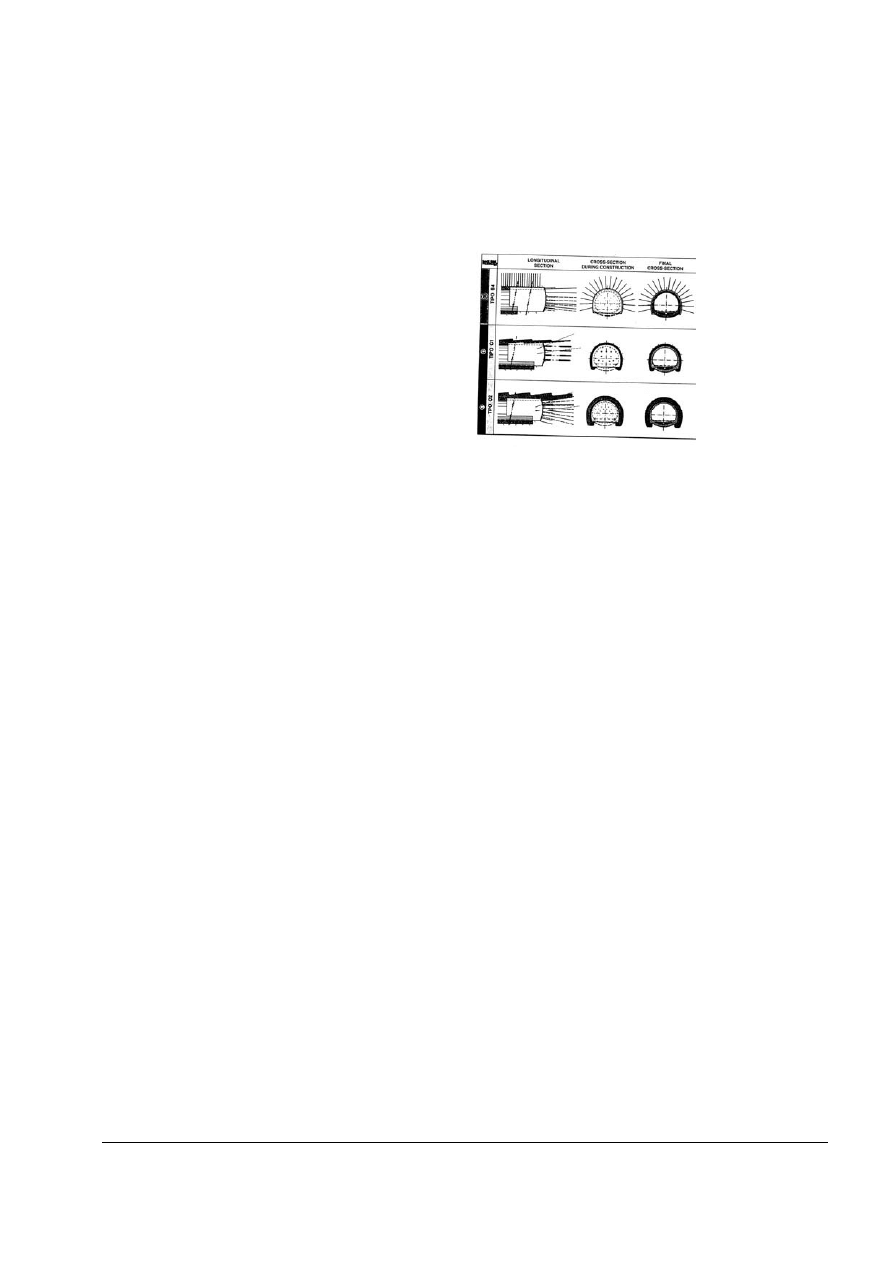
Examples of standard cross sections used
f o r t he n ew h i g h-s p ee d - ra i l t un ne l s
t h rou gh th e Ape nnines (f rom Lunard i ,
2000)
Wyszukiwarka
Podobne podstrony:
Duffaut Ideas on tunnel stability
Effecto of glycosylation on the stability of protein pharmaceuticals
1948 On the stability and instability of shock waces Thomas
HUME AND?SCARTES ON THE THEORY OF IDEAS
Hoppe Reflections on the Origin and the Stability of the State
Report on Progress toward Security and Stability in Afghanistan 1230
Report on Mutual Assured Stability Essential Components and Near Term Actions
More on hypothesis testing
ZPSBN T 24 ON poprawiony
KIM ON JEST2
vii w stabilnosc prionow
Parzuchowski, Purek ON THE DYNAMIC
4 stabilnosc
Foucault On Kant
G B Folland Lectures on Partial Differential Equations
free sap tutorial on goods reciept
5 STABILNOSC id 40487 Nieznany (2)
więcej podobnych podstron