2002-03 SOI/DT-eb LPD/C&F-hd PLT/ASQ-apdv
1
599 35 16-00
SERVICE MANUAL
WASHING
© ELECTROLUX ZANUSSI S.p.A.
Spares Operations Italy
Corso Lino Zanussi, 30
Publication
number
I - 33080 PORCIA /PN (ITALY)
599 35 16-00
Fax +39 0434 394096
Edition: 2002-03-21
EN
Washing machines:
guide to diagnostics for
EWM1000 electronic
control system

2002-03 SOI/DT-eb LPD/C&F-hd PLT/ASQ-apdv
2
599 35 16-00

2002-03 SOI/DT-eb LPD/C&F-hd PLT/ASQ-apdv
3
599 35 16-00
Table of contents
1 INTRODUCTION........................................................................................................................................ 5
1.1 Purpose
of
this manual ....................................................................................................................... 5
1.2 Procedure ........................................................................................................................................... 5
2 DIAGNOSTICS SYSTEM .......................................................................................................................... 6
2.1
ACCESS TO THE DIAGNOSTICS CYCLE – version with horizontal pushbuttons ........................... 6
2.2
ACCESS TO THE DIAGNOSTICS CYCLE – version with vertical pushbuttons ............................... 6
2.3
PHASES OF THE DIAGNOSTICS CYCLE ........................................................................................ 7
3 ALARMS .................................................................................................................................................... 8
3.1 Displaying
user alarms ....................................................................................................................... 8
3.1.1
Alarm display during normal operation ...................................................................................... 8
3.2 Reading
the alarms............................................................................................................................. 9
3.2.1 Displaying the alarm .................................................................................................................... 9
3.2.2 Examples
of alarm display........................................................................................................... 9
3.2.3
Status of alarms during the diagnostics cycle ............................................................................. 9
3.3 Rapid
reading of alarms.................................................................................................................... 10
3.3.1 Version
with
horizontal pushbuttons.......................................................................................... 10
3.3.2 Version
with
vertical pushbuttons .............................................................................................. 10
3.4 CANCELLING
THE LAST ALARM ................................................................................................... 11
3.4.1
CANCELLING AN ALARM – VERSION WITH HORIZONTAL PUSHBUTTONS..................... 11
3.5
CANCELLING AN ALARM – VERSION WITH VERTICAL PUSHBUTTONS.................................. 11
3.6 TABLE
OF
ALARM CODES ............................................................................................................. 12
3.7
Notes concerning certain alarm codes ............................................................................................. 14
4
THE DIAGNOSTICS PROGRAMME CANNOT BE ACCESSED ............................................................ 15
4.1.1
All LEDs on the circuit are board switched off........................................................................... 15
4.1.2
Some of the LEDs on the circuit board light. ............................................................................. 15
5 TROUBLESHOOTING
ACCORDING TO ALARM CODES .................................................................... 16
E11: Difficulty in filling during wash phase ........................................................................................... 16
E13: Water leakage .............................................................................................................................. 18
E21: Difficulties in draining ................................................................................................................... 20
E23: Malfunction of drain pump triac.................................................................................................... 22
E24: «sensing» circuit of the component (triac) that controls the drain pump faulty ........................... 22
E33: Incongruence between closure of anti-boiling and 1st level contacts of pressure switch ........... 24
E35: Water level too high ..................................................................................................................... 26
E36: «sensing» circuit of anti-boiling pressure switch faulty ................................................................ 27
E37: «sensing» circuit of 1st level pressure switch faulty .................................................................... 27
E39: “HV” «sensing» circuit of anti-overflow pressure switch faulty .................................................... 27
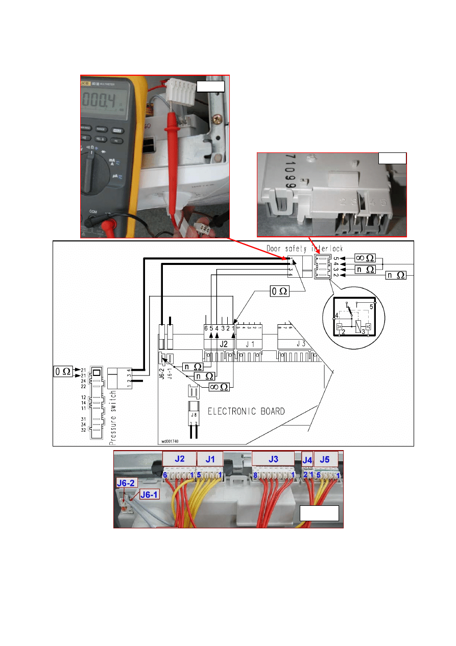
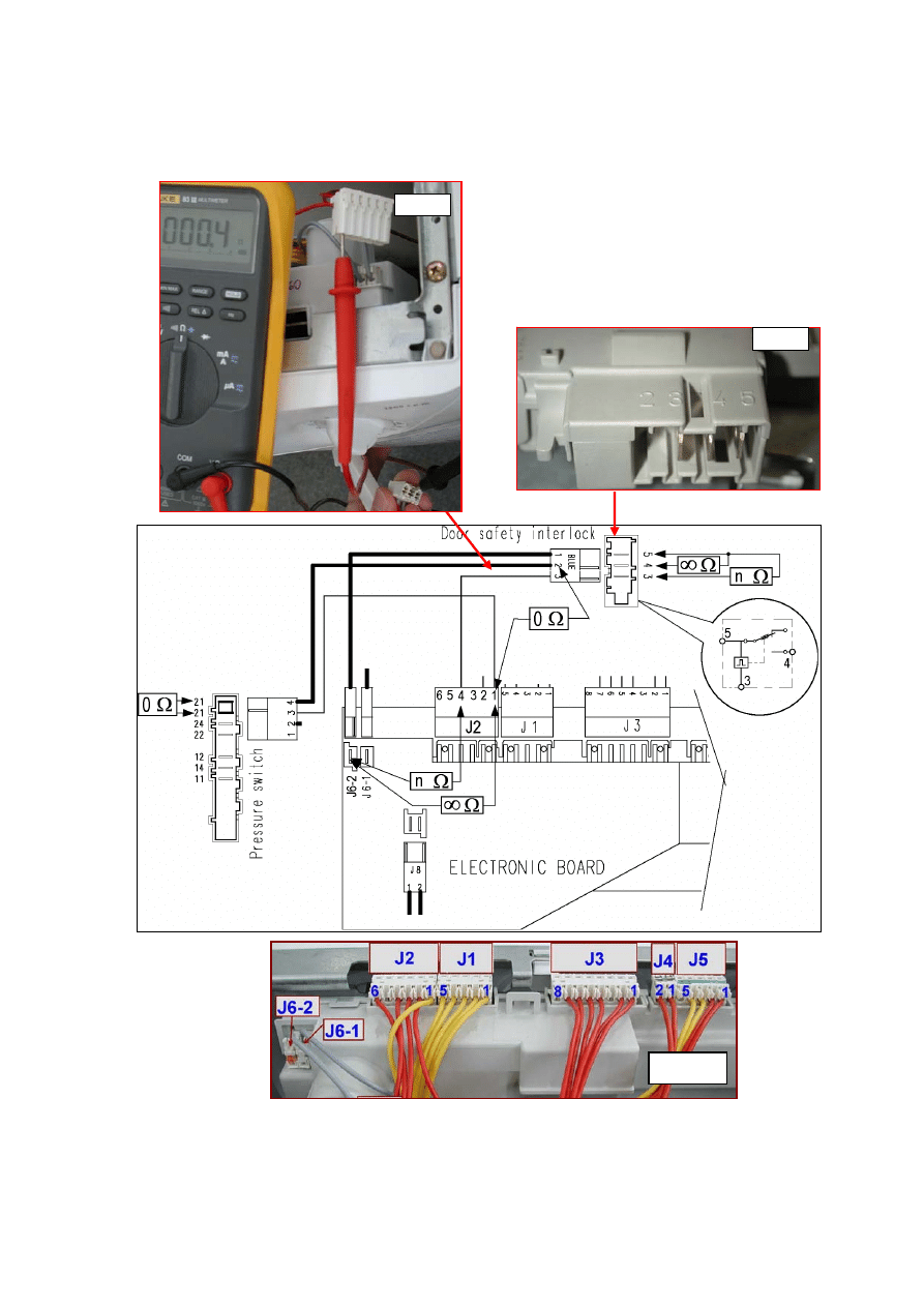
E41: Door open (section 1: device with 3 contacts) ............................................................................. 28
E41: Problems with aperture of door (section 2 – device with 4 connectors) ...................................... 30
E42: Problems with aperture of the door (section 1 – device with 3 contacts) .................................... 32
E42: Problems with aperture of the door (section 2 – device with 4 contacts) .................................... 34
E43: Problems with the triac which actions the door interlock – section 1........................................... 36
E43: Problems with the triac which actions the door interlock – section 2........................................... 38
E44: Door closure «sensing» circuit faulty ........................................................................................... 40
E45: Problems with the «sensing» circuit of the triac that actions the door interlock .......................... 40
E51: Motor power triac short-circuited ................................................................................................. 41
E52: No signal from the motor tachymetric genetaror (section 1)........................................................ 42
E52: No signal from the tachymetric generator (section 2).................................................................. 44
Procedure for checking commutator motors............................................................................... 45
E53: Problems with the «sensing» circuit of the triac which powers the motor ................................... 46
E54: Motor relay contacts sticking........................................................................................................ 47
E61: Insufficient heating during washing.............................................................................................. 48
E62: Overheating during washing ........................................................................................................ 50
E66: The contacts of the heating element power relay are always closed .......................................... 52
E71: NTC washing sensor faulty .......................................................................................................... 53
E82: Error in reading the RESET/OFF position of the programme selector ........................................ 54
E83: Error in reading the programme selector code ............................................................................ 54
E93: Incorrect machine configuration................................................................................................... 55
E94: Incorrect configuration of washing cycle...................................................................................... 55
E95: Communications error between microprocessor and the EEPROM ........................................... 55
E96: Incongruence between control panel version and configuration data ......................................... 55

2002-03 SOI/DT-eb LPD/C&F-hd PLT/ASQ-apdv
4
599 35 16-00
E97: Incongruence between selector version and configuration data ................................................. 55
EA1: Drum positioning system (DSP) faulty (top-loaders only) ........................................................... 56
EB1: Incorrect mains frequency ........................................................................................................... 57
EB2: Mains voltage too high................................................................................................................. 57
EB3: Mains voltage too low .................................................................................................................. 57
6 ELEMENTARY DIAGRAM....................................................................................................................... 58
6.1 With
instantaneous
door locking device ........................................................................................... 58
6.2
With PTC door locking device........................................................................................................... 59
6.2.1
Key to circuit diagram ................................................................................................................ 60
7 CONNECTORS
ON
CIRCUIT BOARD.................................................................................................... 61
8 BURNING
ON
THE
CIRCUIT BOARD .................................................................................................... 62
8.1 COMPONENTS
SIDE (common) ..................................................................................................... 62
8.2
PUSHBUTTON – LED SIDE (HORIZONTAL BUTTONS)................................................................ 63
8.3
PUSHBUTTON – LED SIDE (VERTICAL BUTTONS) ..................................................................... 64

2002-03 SOI/DT-eb LPD/C&F-hd PLT/ASQ-apdv
5
599 35 16-00
1 INTRODUCTION
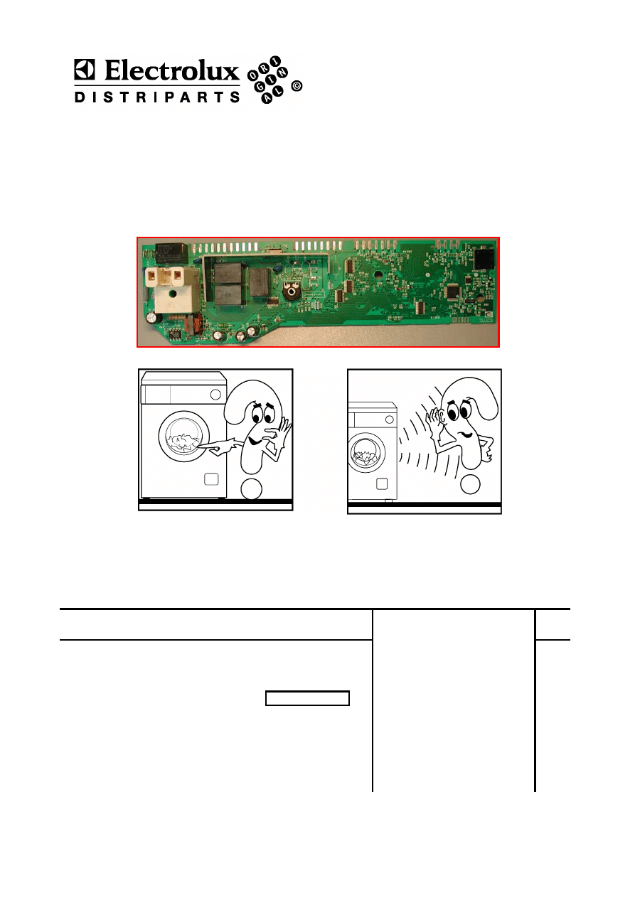
1.1 Purpose of this manual
The purpose of this Service Manual is to provide a simple and clear description of the
procedure to be followed by service engineers when confronted by problems identified by
the various alarm codes generated by appliances with the EWM1000 electronic control
system.
Depending on the configuration of the appliance, the alarm codes may be displayed
partially or completely to the user (the alarm codes are generally displayed partially).
The diagnostics system can be used by service engineers for the following purposes:
♦ To read the alarms
♦ To cancel alarm conditions stored in memory
♦ To test the operation of the appliance
1.2 Procedure
1.
Identify the type of control system (i.e. with horizontal or vertical buttons) and access
the diagnostics cycle
(see page 6)
2.
Read the alarm code stored in memory
(page 9)
and refer to the instructions for the
corresponding alarm code
page 12-13
.
3.
Cancel the alarm stored in memory
(page 11)
4.
If access to the diagnostics cycle is not possible, refer to the section “Access to
diagnostics system impossible”
(page 15)
5.
If the main PCB is replaced, check that there are no burned parts
(see page 62 - 64)
6.
After any repair, always check the operation of the appliance using the diagnostics
cycle
(page 6)
7.
Cancel any alarms stored in memory during the diagnostics procedure
(page11)
2002-03 SOI/DT-eb LPD/C&F-hd PLT/ASQ-apdv
6
599 35 16-00
2 DIAGNOSTICS
SYSTEM
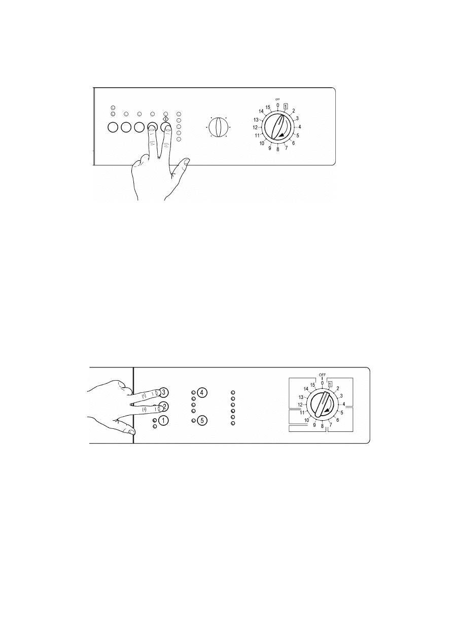
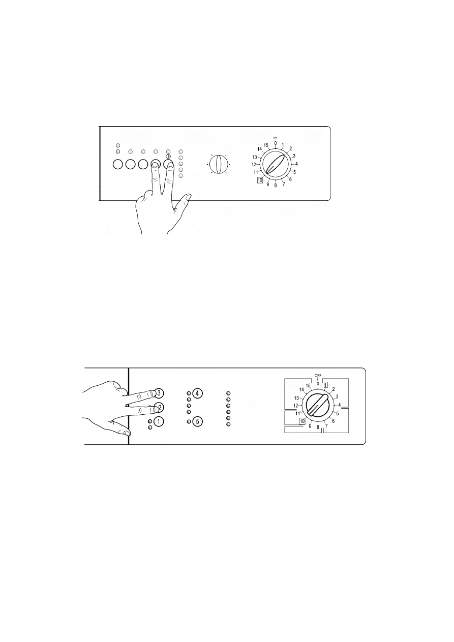
2.1 ACCESS TO THE DIAGNOSTICS CYCLE – version with horizontal pushbuttons
1. Switch off the appliance.
2. Press and hold down the START/PAUSE button and any one of the OPTION buttons simultaneously.
3. Holding down both buttons, switch the appliance on by turning the programme selector one position
clockwise.
4. Continue to hold down the START/PAUSE button and the OPTION button until the LEDs begin to flash
(at least 2 seconds).
IMPORTANT: The position of the START/PAUSE button varies according to the model, and is
therefore not always the same.
In the first position, the cycle tests the operation of the buttons and the relative LEDs. If the selector is
turned clockwise, the cycle performs the diagnostics for the various components and reads the alarm
codes.
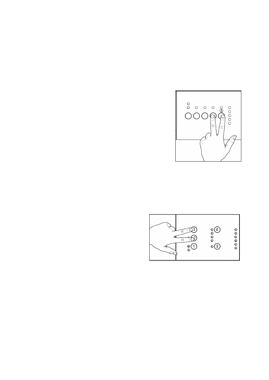
2.2 ACCESS TO THE DIAGNOSTICS CYCLE – version with vertical pushbuttons
1. Switch off the appliance.
2. Press and hold down buttons 2 and 3.
3. Holding down both buttons, switch the appliance on by turning the programme selector one position
clockwise.
4. Continue to hold down buttons 2 and 3 until the LEDs begin to flash (at least 2 seconds).
In the first position, the cycle tests the operation of the buttons and the relative LEDs. If the selector is
turned clockwise, the cycle performs the diagnostics for the various components and reads the alarm
codes.
2002-03 SOI/DT-eb LPD/C&F-hd PLT/ASQ-apdv
7
599 35 16-00
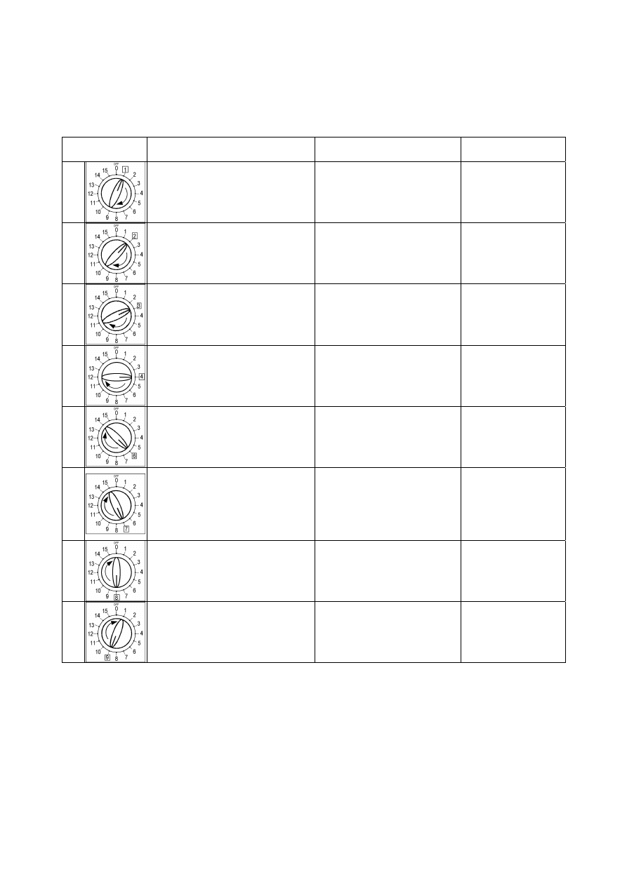
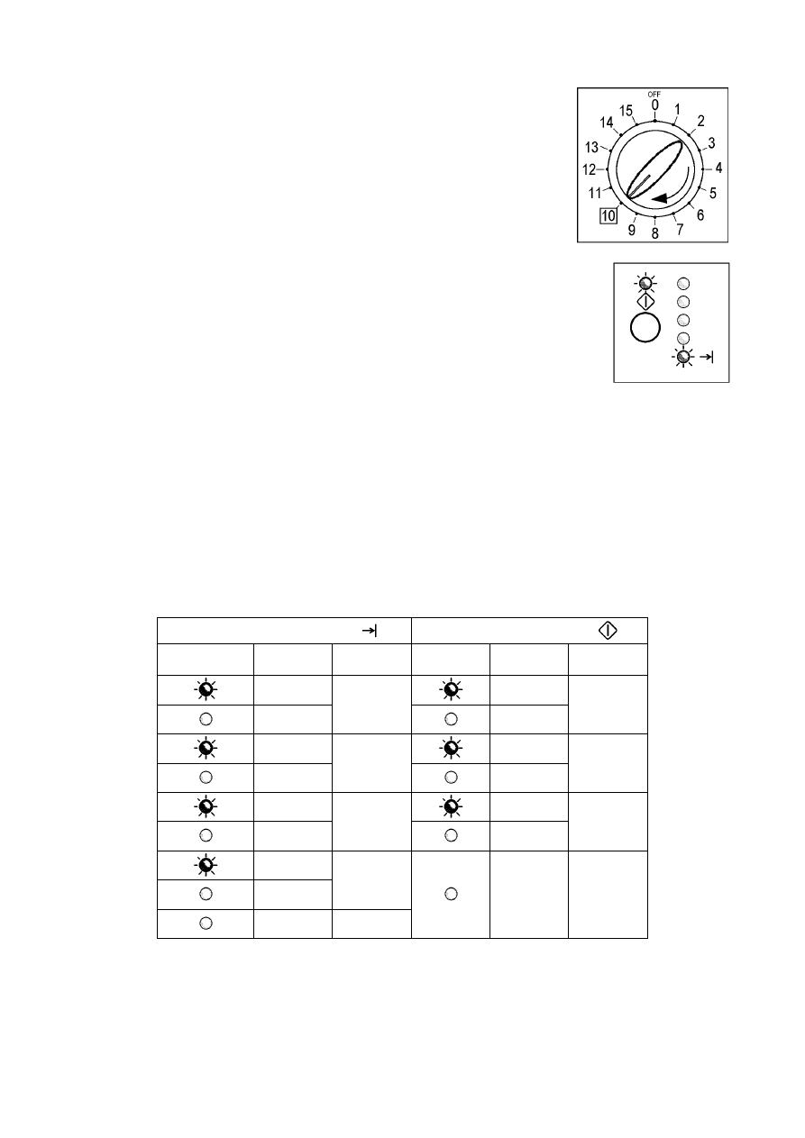
2.3 PHASES
OF
THE
DIAGNOSTICS CYCLE
After accessing the diagnostics cycle, and irrespective of the type of control board fitted to the appliance
(i.e. vertical or horizontal buttons) and the configuration of the selector, turn the programme selector
clockwise to perform the diagnostics cycle for the various components and to read the alarms.
All the alarms are enabled during the diagnostics cycle.
Position of
selector
Components activated
Conditions of operation
Function tested
1
- All the LEDs light in sequence
- When a button is pressed, the
corresponding LED lights (and
the buzzer may sound)
Always enabled
Operation of the
user interface
2
- Door safety interlock
- Washing solenoid valve
Door locked
Water level lower than anti-
overflow level
Maximum time 5 minutes
Water ducted
through washing
compartment
3
- Door safety interlock
- Pre-wash solenoid valve
Door locked
Water level lower than anti-
overflow level
Maximum time 5 minutes
Water ducted
through pre-wash
(bleach)
compartment
4
- Door safety interlock
- Washing and pre-wash solenoid
valves
Door locked
Water level lower than anti-
overflow level
Maximum time 5 minutes
Water ducted
through conditioner
compartment
6
- Door safety interlock
- Wash solenoid (if the water in
the tub is below 1st level)
- Heating element
Door locked
Water level > 1st level
Maximum time 10 minutes or
up to 90°C (*)
Heating
7
- Door safety interlock
- Wash solenoid (if the water in
the tub is below 1st level)
- Motor (55 rpm clockwise, 55
rpm anti-clockwise, impulse at
250 rpm)
Door locked
Water level > 1st level
Check for leaks
from the tub
8
- Door safety interlock
- Drain pump
- Motor up to 650 rpm then at
maximum spin speed
Door locked
Water level lower then anti-
boiling level for spinning
Drain and spin,
check for
congruence in
closure of pressure
switch levels
9
Only for top-loaders with drum
positioning system:
- Door safety interlock
- Motor (25 rpm)
- Drain pump
Door locked
Water level lower then anti-
boiling level
Maximum time 2 minutes
Test for positioning
of drum
(*) In most cases, this time is sufficient to check the heating function. However, the time can be increased by
repeating the heating phase without draining the water: pass for a moment to a different phase of the
diagnostics cycle and then back to the heating check phase (if the temperature is higher than 80°C,
heating does not take place).
2002-03 SOI/DT-eb LPD/C&F-hd PLT/ASQ-apdv
8
599 35 16-00
3 ALARMS
3.1 Displaying user alarms
Operation of the alarms is configurable. Therefore, depending on the model, the alarms may be
displayed partially or entirely to the user.
Normally, all alarms except those shown below are displayed to the user:
-
E61 (insufficient heating during the washing phase),
-
E83 (error in reading the selector position)
-
EA1 (error in positioning of the drum – top-loaders only)
The alarms are enabled during the execution of the washing programme with the exception of the alarms
relative to the configuration and the power supply (voltage and frequency), which are also displayed during
the programme selection phase.
Except where specified, the door can generally be opened when an alarm condition occurs on condition that:
• The water in the tub is lower than 1st level
• The temperature of the water is lower than 40°C
Certain alarms require a drain cycle (for reasons of safety) before the door can be opened:
• Cooling water fill phase if the temperature is higher than 60°C
• Drain until both contacts of the pressure switch (1st level and anti-boiling) close on “EMPTY” in a
maximum time of 5 minutes.
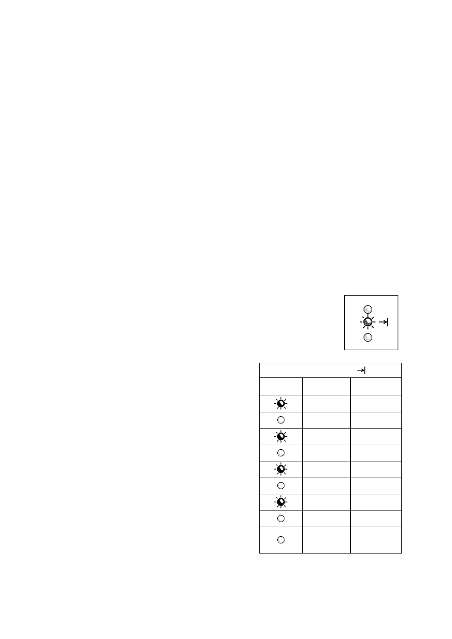
3.1.1
Alarm display during normal operation
The family of alarms is displayed to the user by a repeating sequence during which
the END OF CYCLE LED flashes (0.4 seconds ON, 0.4 seconds OFF, with a pause
of 2.5 seconds between each sequence) This LED is featured on all models,
although it may be configured in different positions. Configuration errors are
displayed flashing of all the LEDs.
End of cycle LED
ON/OFF
Time
(seconds)
Value
0.4 1
0.4
0.4 2
0.4
0.4 3
0.4
0.4
4
0.4
For example, if the user should forget to close the door, alarm
condition E41 will be displayed about 15 seconds after the
cycle is started. The cycle is paused and the END OF CYCLE
LED flashes repeatedly in the sequence shown in the table
opposite.
The four flashes indicate the first two digits of alarm E41
(alarms relative to the same function are grouped into
families).
In this case, when the door is closed, it is sufficient to press
START to resume the programme.
2.5
Pause
between
sequences
2002-03 SOI/DT-eb LPD/C&F-hd PLT/ASQ-apdv
9
599 35 16-00
3.2 Reading the alarms
Proceed as follows to read the last alarm condition stored in the EEPROM on the
control board:
• Access diagnostics mode.
• Irrespective of the type of control board and configuration, turn the
programme selector clockwise to the tenth position.
3.2.1
Displaying the alarm
The alarm is displayed by a repeated flashing sequence of the two LEDs (0.4
seconds ON, 0.4 seconds OFF, with a pause of 2.5 seconds between each
sequence). The buzzer (if featured) sounds a series of “beeps” in synchronization
with the flashing of the LEDs.
• END OF CYCLE indicator → indicates the first digit of the alarm code (family)
• START/PAUSE → indicates the second digit of the alarm code (number
within the family).
These two LEDs are present on all models (though configured in different
positions) and flash simultaneously.
Notes:
• The first letter of the alarm code “E” (Error) is not displayed since it is the same for all alarm codes.
• The alarm code families are expressed in hexadecimal form. In other words:
→ A is represented by 10 flashes
→ B is represented by 11 flashes
→ ...
→ F is represented by 15 flashes
• Configuration errors are displayed by the flashing of all the LEDs (user interface not configured).
3.2.2
Examples of alarm display
Example: Alarm E43 (problems with the door safety interlock triac) will be displayed as follows:
• four flashes of the END OF CYCLE LED indicate the first digit E43;
• three flashes of the START/PAUSE LED indicate the second digit E43;
END OF CYCLE LED
START/PAUSE LED
ON/OFF
Time
(seconds)
Value ON/OFF
Time
(seconds)
Value
0.4
0.4
0.4
1
0.4
1
0.4
0.4
0.4
2
0.4
2
0.4
0.4
0.4
3
0.4
3
0.4
0.4
4
2.5 Pause
3,3 Pause
3.2.3
Status of alarms during the diagnostics cycle
All the alarms are enabled during the components diagnostics test.
2002-03 SOI/DT-eb LPD/C&F-hd PLT/ASQ-apdv
10
599 35 16-00
3.3 Rapid reading of alarms
The last alarm can be displayed even if the programme selector is not in the tenth position (diagnostics) or if
the appliance is in normal operating mode (e.g. while the washing programme is in operation):
3.3.1
Version with horizontal pushbuttons
→ Press START/PAUSE and any one of the option buttons
simultaneously for at least two seconds: the LEDs first switch off,
and then display the flashing sequence corresponding to the
alarm condition.
→ The alarm sequence continues as long as the two buttons are
held down.
→ The alarm reading procedure is as described in paragraph 3.2.1.
→ While the alarms are displayed, the current cycle being
performed continues or, if the appliance is in the programme
selection phase, the options previously selected remain in
memory.
3.3.2 Version
with
vertical
pushbuttons
→ Press buttons 3 and 2 for at least two seconds: the
LEDs first switch off, and then display the flashing
sequence corresponding to the alarm condition.
→ The alarm sequence continues as long as the two
buttons are held down.
→ The alarm reading procedure is as described in
paragraph 3.2.1.
→ While the alarms are displayed, the current cycle
being performed continues or, if the appliance is in
the programme selection phase, the options
previously selected remain in memory.
2002-03 SOI/DT-eb LPD/C&F-hd PLT/ASQ-apdv
11
599 35 16-00
3.4 CANCELLING THE LAST ALARM
It is good practise to cancel the alarm condition stored in memory:
• after reading the alarm, in order to check whether it occurs again during the diagnostics test.
• after repairing the appliance, in order to check whether the alarm occurs again during testing.
3.4.1
CANCELLING AN ALARM – VERSION WITH HORIZONTAL PUSHBUTTONS
1. Access alarm reading mode (tenth selector position,
see paragraph 3.2
)
2. Press and hold down START/PAUSE and any one of the option keys simultaneously.
3. Hold the START/PAUSE and OPTION button down until the LEDs begin to flash (about 5 seconds)
IMPORTANT: The position of the START/PAUSE button varies according to the model, and is
therefore not always the same.
3.5 CANCELLING AN ALARM – VERSION WITH VERTICAL PUSHBUTTONS
1. Access alarm reading mode (tenth selector position,
see paragraph 3.2
)
2. Press and hold down buttons 3 and 2 simultaneously.
3. Hold down buttons 3 and 2 until the LEDs begin to flash (about 5 seconds)

2002-03 SOI/DT-eb LPD/C&F-hd PLT/ASQ-apdv
12
599 35 16-00
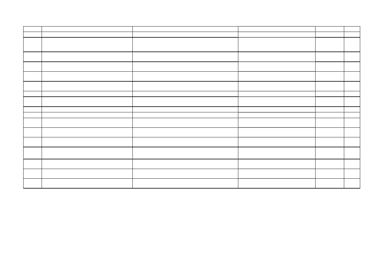
3.6 TABLE OF ALARM CODES
Alarm
Description
Possible fault
Action/Machine status
Reset
Page
E11
Difficulty in filling during wash phase
Tap closed or water pressure insufficient; Drain hose
incorrectly positioned; Water fill solenoid faulty; Leaks
from pressure switch hydraulic circuit; Pressure switch
faulty; Wiring faulty; Circuit board faulty.
Cycle paused, door closed
Start
16
E13
Water leakage
Drain hose incorrectly positioned; Water pressure
insufficient; Water fill solenoid faulty; Leaks or blockage in
pressure switch hydraulic circuit; Pressure switch faulty;
Circuit board faulty.
Cycle paused, door closed
Start
18
E21
Difficulties in draining
Drain hose kinked/blocked/incorrectly positioned; Drain
filter clogged or dirty; Drain pump faulty; Pressure switch
faulty; Wiring faulty; Circuit board faulty; Current leakage
from heating element to ground.
Cycle paused
Start
20
E23
Drain pump triac faulty
Drain pump faulty; Wiring faulty; Circuit board faulty.
Safety drain - Cycle stopped, door open
Selector on “0”
22
E24
Problems with «sensing» of drain pump triac Circuit board faulty.
Safety drain – Cycle stopped, door
released
Selector on “0”
22
E33
Incongruence between contact closure of anti-
boiling and 1st level of pressure switch
Pressure switch faulty; Current leakage from heating
element to ground; Heating element; Wiring faulty; Circuit
board faulty.
Safety drain - Cycle stopped, door open
Selector on “0”
24
E35
Water overflow
Water fill solenoid faulty; Leaks from pressure switch
hydraulic circuit; Pressure switch faulty; Wiring faulty;
Circuit board faulty.
Cycle blocked, door closed. Safety drain.
Drain pump (sequence 5 min. ON - 5 min.
OFF)
Selector on “0”
26
E36
«sensing» circuit of anti-boiling pressure
switch faulty
Circuit board faulty.
Cycle blocked, door closed
Selector on “0”
27
E37
«sensing» circuit of 1st level faulty
Circuit board faulty.
Cycle blocked, door closed
Selector on “0”
27
E39
HV «sensing» circuit of anti-flooding pressure
switch faulty
Circuit board faulty.
Cycle blocked, door closed
Selector on “0”
27
E41
Door open
Door safety interlock faulty; Wiring faulty;
Circuit board faulty.
Cycle paused
Start
28
E42
Problems with aperture of door
Door safety interlock faulty; Wiring faulty;
Circuit board faulty
Cycle paused
Start or
Selector on “0”
32
E43
Power triac on door interlock faulty
Door safety interlock faulty; Wiring faulty;
Circuit board faulty.
Safety drain, door released
Selector on “0”
36
E44
Door interlock «sensing» faulty
Circuit board faulty.
Safety drain, door released
Selector on “0”
40
E45
«sensing» on door interlock triac faulty
Circuit board faulty.
Safety drain, door released
Selector on “0”
40
E51
Motor power triac short-circuited
Circuit board faulty;
Current leakage from motor or wiring.
Cycle blocked, door closed (after 5
attempts in diagnostics or immediate
during selection)
Selector on “0”
42
E52
No signal from motor tachimetric generator
Motor faulty; Wiring faulty;
Circuit board faulty.
Cycle blocked, door closed (after 5
attempts in diagnostics or immediate
during selection)
Selector on “0”
46
2002-03 SOI/DT-eb LPD/C&F-hd PLT/ASQ-apdv
13
599 35 16-00
Alarm
Description
Possible fault
Action/Machine status
Reset
Page
E53
«sensing» circuit on motor triac faulty
Circuit board faulty.
Cycle blocked
Selector on “0”
47
E54
Motor relay contacts sticking
Circuit board faulty;
Current leakage from motor or wiring.
Cycle blocked, door closed (after 5
attempts in diagnostics or immediate
during selection)
Selector on “0”
48
E61
Insufficient heating during washing
NTC sensor faulty; Heating element faulty; Wiring faulty;
Circuit board faulty.
Heating phase skipped
---
50
E62
Overheating during washing
NTC sensor faulty; Heating element faulty; Wiring faulty;
Circuit board faulty.
Safety drain (with cooling water fill) - Stop
with door open
Selector on “0”
52
E66
Power relay for heating element faulty
Circuit board faulty; Current leakage from heating element
or wiring to ground.
Safety drain (with cooling water fill) - Stop
with door open
Selector on “0”
53
E71
NTC washing sensor faulty
NTC sensor faulty; Wiring faulty;
Circuit board faulty.
Heating phase skipped
---
54
E82
Error in reset position of selector
Circuit board faulty.
Cycle cancelled
Selector on “0”
54
E83
Error in reading selector position
Configuration data incorrect; Circuit board faulty.
During the cycle continues normally,
switches off completely during selection
---
55
E93
Incorrect machine configuration
Configuration data incorrect; Circuit board faulty.
Appliance blocked
Selector on “0”
55
E94
Incorrect washing cycle configuration
Configuration data incorrect; Circuit board faulty.
Appliance blocked
Selector on “0”
55
E95
Communications error between
microprocessor and EEPROM
Circuit board faulty.
Appliance blocked
Selector on “0”
55
E96
Incongruence between hardware version and
configuration.
Configuration data incorrect; Circuit board faulty.
Appliance blocked
Selector on “0”
55
E97
Incongruence between programme selector
and cycle configuration
Configuration data incorrect; Circuit board faulty.
Appliance blocked
Selector on “0”
55
EA1
Drum positioning system (DSP) faulty
Wiring faulty; Circuit board faulty; DSP sensor faulty;
Motor drive belt broken.
Drum positioning phase skipped
Selector on “0”
56
EB1
Power supply frequency of appliance
incorrect
Mains power supply problems (incorrect / interference);
Circuit board faulty.
Cycle blocked until normal power supply
conditions are restored
Selector on “0”
57
EB2
Voltage too high
Mains power supply problems (incorrect / interference);
Circuit board faulty.
Cycle blocked until normal power supply
conditions are restored
Selector on “0”
57
EB3
Voltage too low
Mains power supply problems (incorrect / interference);
Circuit board faulty.
Cycle blocked until normal power supply
conditions are restored
Selector on “0”
57

2002-03 SOI/DT-eb LPD/C&F-hd PLT/ASQ-apdv
14
599 35 16-00
3.7 Notes concerning certain alarm codes
Configuration alarms
E93-E96
: If these alarms are generated (when the appliance is switched on), operation of the appliance is blocked and all the LEDs
light. The diagnostics procedure cannot be accessed; the only option is to switch the appliance OFF (by turning the selector to position “0”).
Configuration alarm
E94
: For this alarm code, only the family for alarm “9” is displayed; the diagnostics procedure cannot be accessed, and the “rapid alarm
display” function cannot be used.
Alarms
EB1-EB2-EB3
: In the event of problems with the mains power supply, the appliance remains in alarm mode until the mains frequency or voltage are
restored to the correct value or the appliance is switched off (by turning the programme selector to “0”). The family of alarm “B” is displayed; the diagnostics
procedure cannot be accessed, and the “rapid alarm display” function cannot be used. The complete alarm code can be read only when the abnormal situation
has ceased.
Alarms
E51- E52
: During the diagnostics test, all the alarms are displayed. Normally, when the programme selector is turned from one test phase to another,
the appliance exits the alarm condition and performs the phase selected. This does not take place in the case of alarms E51 (power triac on motor short-
circuited) and E52 (no signal from the tachymetric generator on the motor): in these cases, the only option to exit the alarm condition is to switch the appliance
OFF by turning the selector to position “0” (reset).
2002-03 SOI/DT-eb LPD/C&F-hd PLT/ASQ-apdv
15
599 35 16-00
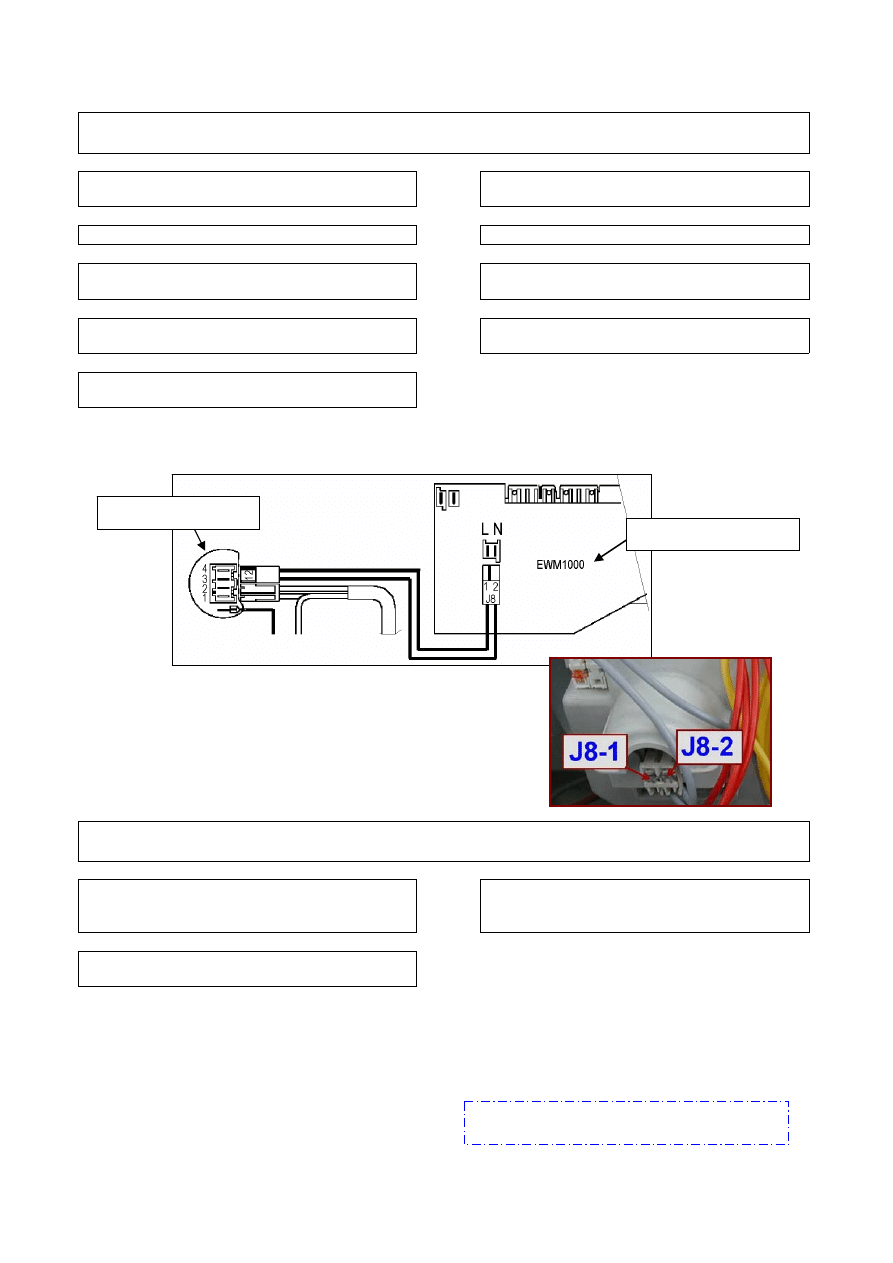
4 THE
DIAGNOSTICS
PROGRAMME CANNOT BE ACCESSED
4.1.1
All LEDs on the circuit are board switched off.
Are the power cable and connection OK?
No
→
Replace or repair the power cable, check the
connector
Yes
↓
Does the suppressor function correctly?
No
→
Replace the suppressor
Yes
↓
Is the wiring from the suppressor to the circuit
board (connectors
J8.1-J8.2
) OK?
No
→
Replace or repair the wiring
Yes
↓
Does the programme selector function
correctly?
No
→
Replace or repair the knob or knob spindle
Yes
↓
Replace the circuit board and perform the
diagnostics programme.
4.1.2
Some of the LEDs on the circuit board light.
Do the keys move without hindrance in the
housings in the control panel and correctly
action the corresponding buttons?
No
→
Solve the mechanical problems
(control panel / keys / spindles)
Yes
↓
Replace the circuit board and perform the
diagnostics programme.
If there are traces of burning on the circuit
board, refer to pages. 62-64
Suppressor
Circuit board
2002-03 SOI/DT-eb LPD/C&F-hd PLT/ASQ-apdv
16
599 35 16-00
YES
Access the diagnostics cycle and duct water through all the compartments
(phases 2,3,4)
Is water ducted through all the compartments?
5 TROUBLESHOOTING
ACCORDING TO ALARM CODES
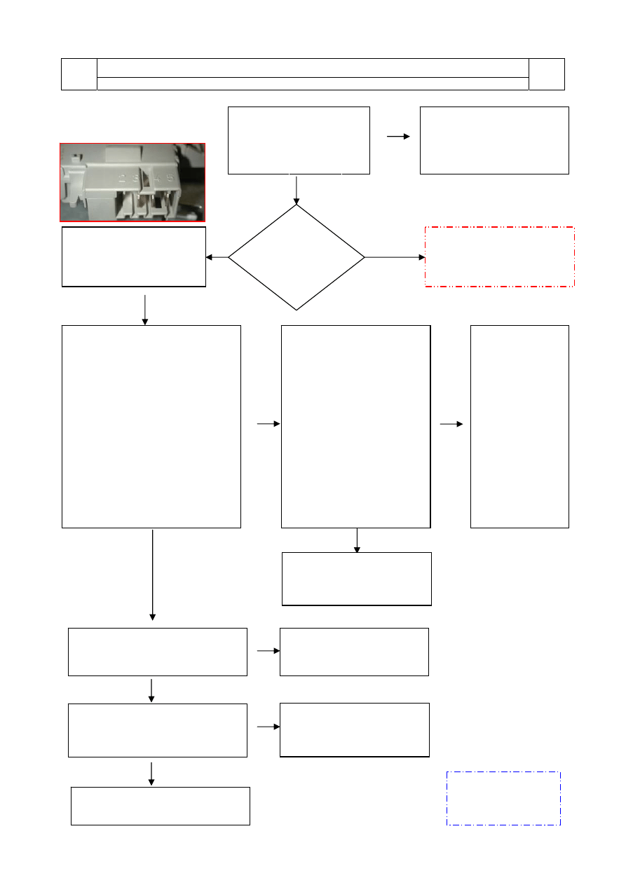
E11: Difficulty in filling during wash phase
E11
Maximum water fill time for each pressure switch level
(this time is reset to zero each time the level is reached)
E11
Tests to be performed:
YES
YES
YES
YES
YES
NO
YES
Position the drain circuit correctly and restart the
diagnostics cycle to check for further alarm
conditions.
NO
Repair the hydraulic circuit of the pressure
switch and restart the diagnostics cycle to check
for further alarm conditions.
NO
Replace the pressure switch and restart the
diagnostics cycle to check for further alarm
conditions.
Replace the circuit board and restart the diagnostics cycle to check for further alarms
NO
Replace or repair the wiring and restart the
diagnostics cycle to check for further alarm
conditions.
Is the drain hose positioned
correctly so as not to create the
siphon effect?
(fig.16)
Is the hydraulic circuit of the
pressure switch efficient
(leaks/blockage)?
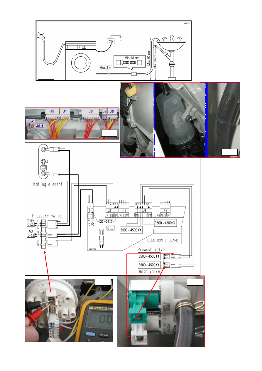
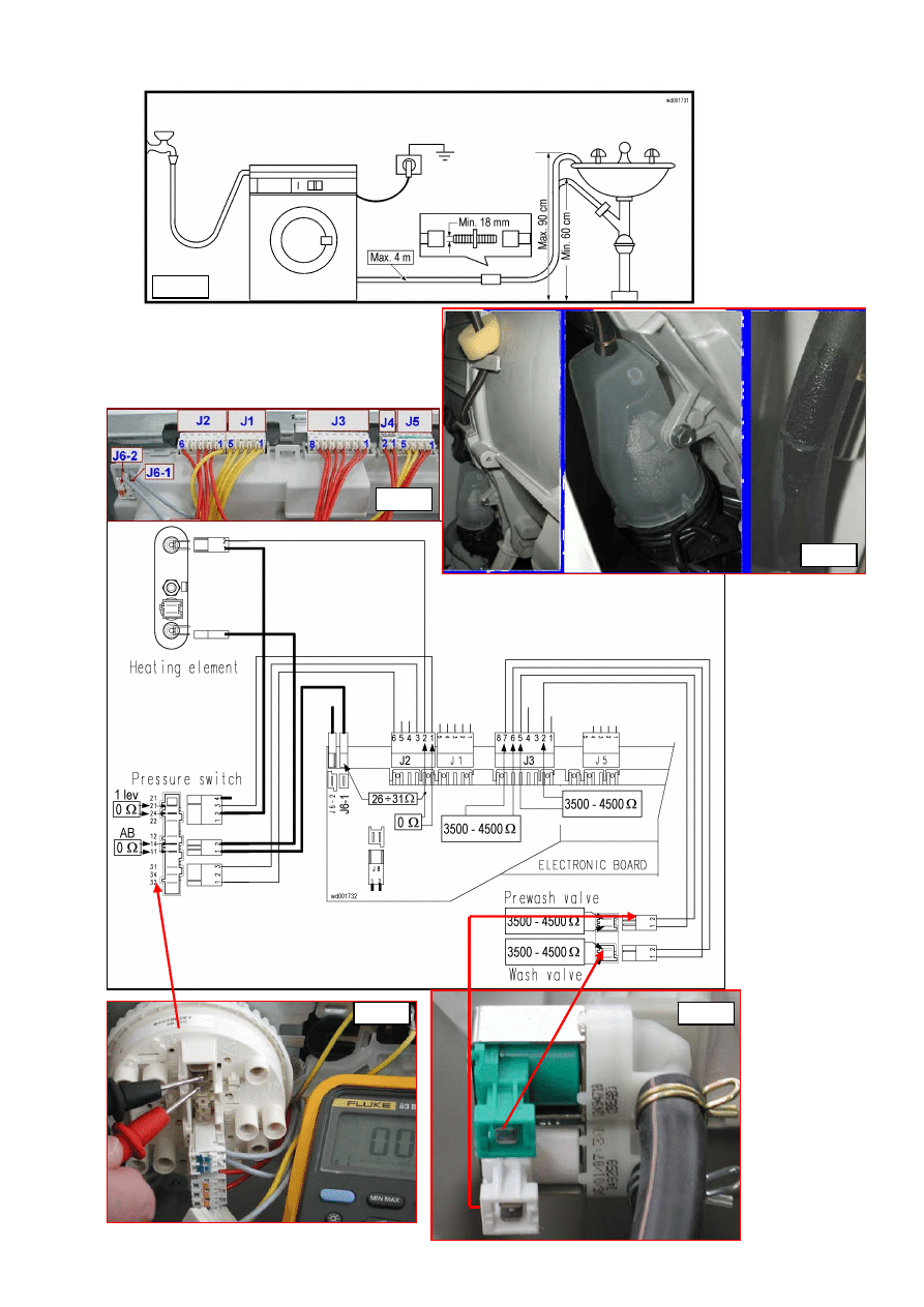
Fig. 2
Does the pressure switch close the
contacts correctly after filling with
water up to door level? (contacts
closed between 11-14, 21-24
, fig 3)
Is the wiring between the pressure
switch and the circuit board
connectors efficient? Measure the
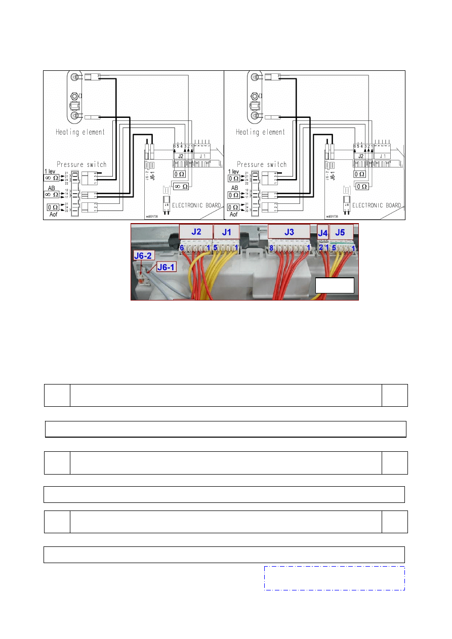
resistance of the heater across J2-1
and J2-2 (closed circuit) and across
J2-2 and J6-1.
(fig.1)
(about 27
Ω at 1950W-230V)
NO
Check that the tap is open, that the mains
water pressure is sufficient and that the hoses
are correctly connected and not kinked.
Do any or all the solenoids fail to function?
NO Replace the solenoid and restart the diagnostics
cycle to check for further alarm conditions.
Is the ohmic resistance of the solenoid about 3.5
– 4.5 K
Ω? (measure directly on the solenoid
without wiring) -
see fig. 4-
NO
YES
NO
Replace or repair the wiring and restart the
diagnostics cycle to check for further alarm
conditions.
Re-attach the connector and measure about 3.5
–4.5 K
Ω on the solenoid wiring connector
(circuit board side)
(fig.1)
: across J3-7 and J3-6
(washing) and across J3-2 and J3-5 (prewash).
Is the solenoid wiring OK?
YES
Replace the circuit board and restart the
diagnostics cycle to check for further alarm
conditions.
NO
Repair the hydraulic circuit and restart the
diagnostics cycle to check for further alarms.
Is the hydraulic circuit efficient
(leaks)?
If there are traces of burning on the circuit
board, refer to pages 62-64
2002-03 SOI/DT-eb LPD/C&F-hd PLT/ASQ-apdv
17
599 35 16-00
E11
fig. 4
fig. 16
fig. 2
fig. 3
fig. 1
2002-03 SOI/DT-eb LPD/C&F-hd PLT/ASQ-apdv
18
599 35 16-00
YES
Access the diagnostics cycle and duct water through all the compartment
(phases 2,3,4)
Is water ducted through all the compartments?
E13: Water leakage
E13
Overall maximum water fill time exceeded (the sum of all the water fills between one drain
phase and the next, to avoid exceeding the maximum volume)
E13
Tests to be performed:
YES
YES
YES
YES
NO
YES
Position the drain circuit correctly and restart the
diagnostics cycle to check for further alarm
conditions.
NO
Repair the hydraulic circuit of the pressure
switch and restart the diagnostics cycle to check
for further alarm conditions.
NO
Replace the pressure switch and restart the
diagnostics cycle to check for further alarm
conditions.
Replace the circuit board and restart the diagnostics cycle to check for further alarms
NO
Replace or repair the wiring and restart the
diagnostics cycle to check for further alarm
conditions.
Is the drain hose positioned
correctly so as not to create the
siphon effect?
(fig.16)
Is the hydraulic circuit of the
pressure switch efficient
(leaks/blockage)?
fig.2
Does the pressure switch close the
contacts correctly after filling with
water up to door level? (contacts
closed between 11-14, 21-24
, fig 3)
Re-connect the wiring to the
pressure switch. Is the wiring
efficient? Measure the resistance of
the heater across J2-1 and J2-2
(closed circuit) and across J2-2 and
J6-1.
(fig.1)
(about 27
Ω at 1950W-230V)
NO
Check that the tap is open, that the mains
water pressure is sufficient and that the hoses
are correctly connected and not kinked.
Do any or all the solenoids fail to function?
YES
NO Replace the solenoid and restart the diagnostics
cycle to check for further alarm conditions.
Is the ohmic resistance of the solenoid about 3.5
– 4.5 K
Ω? (measure directly on the solenoid
without wiring) -
see fig. 4-
NO
YES
NO
Replace or repair the wiring and restart the
diagnostics cycle to check for further alarm
conditions.
Re-attach the connector and measure about 3.5
–4.5 K
Ω on the solenoid wiring connector
(circuit board side): across J3-7 and J3-6
(washing) and across J3-2 and J3-5 (prewash)
(fig.1)
. Is the solenoid wiring OK?
YES
Replace the circuit board and restart the
diagnostics cycle to check for further alarm
conditions.
NO
Repair the hydraulic circuit and restart the
diagnostics cycle to check for further alarms.
Is the hydraulic circuit efficient
(leaks)?
If there are traces of burning on the circuit
board, refer to pages 62-64
2002-03 SOI/DT-eb LPD/C&F-hd PLT/ASQ-apdv
19
599 35 16-00
E13
fig. 16
fig. 2
fig. 1
fig. 4
fig. 3
2002-03 SOI/DT-eb LPD/C&F-hd PLT/ASQ-apdv
20
599 35 16-00
NO
NO
NO
YES
NO
NO
NO
NO
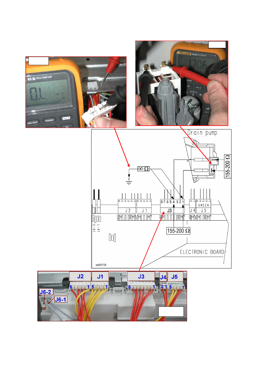
E21: Difficulties in draining
E21
Maximum drain time exceeded (measured for each phase of the cycle)
E21
Tests to be performed:
YES
YES
YES
NO
Clean the filter and restart the diagnostics cycle
to check for further alarm conditions.
Is the drain filter clean?
NO
Disconnect and check the drain system.
Is the drain system OK? (drain hose and
domestic hydraulic circuit)
-fig.16
Does the drain
pump function? (in
the diagnostics
cycle, select
phase
2
fill and
phase 8
drain) (noise from
the pump)
Is the ohmic resistance
of the pump about
155-200
Ω? (measure
directly on the
connector on the
circuit board side
across J3-4 and J3-1
-
fig. 1-
Replace the pump
and restart the
diagnostics cycle to
check for further
alarm conditions.
Is the ohmic
resistance of the
pump about 155-
200
Ω? (measure
directly on the
pump)
-see fig.5-
Check and if necessary replace the wiring and
restart the diagnostics cycle to check for further
alarm conditions.
Is the pump
impeller jammed or
broken?
Is the hydraulic circuit of the pressure switch
efficient? (i.e. not obstructed)
Replace the circuit board and restart the
diagnostics cycle to check for further alarm
conditions.
Repair the hydraulic circuit of the pressure
switch and restart the diagnostics cycle to check
for further alarm conditions.
Clean or replace the drain pump and restart the diagnostics cycle to check
for further alarm conditions.
After draining the water, do the pressure
switch contacts open correctly? (between 11-14,
21-24: contacts open)
fig.3a
Replace the pressure switch and restart the
diagnostics cycle to check for further alarm
conditions.
Is the wiring between the pressure switch and
the circuit board efficient?
(fig.1)
(between J2.1-J2.2; J2.2-J6.1, contact open)
Replace or repair the wiring and restart the
diagnostics cycle to check for further alarm
conditions.
YES
YES
YES
YES
This fault may be caused by the heating element which, if the insulation becomes
detached, may send unusual signals to the circuit board. Generally, this fault occurs
when the heating element is hot. Therefore, before checking (
fig. 15
), operate the
heating element (
phase 6
of diagnostics cycle). If there is no current leakage from
the heating element, replace the circuit board and restart the diagnostics cycle to
check for further alarm conditions.
If there are
traces of burning
on the circuit
board, refer to
pages. 62-64
2002-03 SOI/DT-eb LPD/C&F-hd PLT/ASQ-apdv
21
599 35 16-00
E21
fig. 16
fig. 3a
fig. 15
fig. 1
fig. 5
2002-03 SOI/DT-eb LPD/C&F-hd PLT/ASQ-apdv
22
599 35 16-00
NO
NO
YES
NO
YES
YES
E23
E23: Malfunction of drain pump triac
E23
Tests to be performed:
E24
E24: «sensing» circuit of the component (triac) that controls the drain pump faulty
E24
Is the resistance of the pump
about 150-200
Ω? (measure
across connectors J3-4 on J3-
1 circuit board side –
fig.1
)
Is the resistance of the pump
about 150-200
Ω?
(measure directly on the
pump)
-see fig.5-
Check and if necessary
replace the wiring and restart
the diagnostics cycle to check
for further alarm conditions.
Measure across connectors J3-4 / J3-1 and the
structure of the appliance.
- fig. 9 -
Is there current leakage?
Replace the main circuit board and restart the
diagnostics cycle to check for further alarm
conditions.
Check and if necessary replace the wiring and
restart the diagnostics cycle to check for further
alarm conditions.
Replace the circuit board and restart the
diagnostics cycle to check for further alarm
conditions.
Replace the pump and restart
the diagnostics cycle to check
for further alarm conditions.
If there are traces of
burning on the circuit
board, refer to pages
62-64
If there are traces of
burning on the circuit
board, refer to pages
62-64
2002-03 SOI/DT-eb LPD/C&F-hd PLT/ASQ-apdv
23
599 35 16-00
E23
fig. 9
fig. 1
fig. 5
2002-03 SOI/DT-eb LPD/C&F-hd PLT/ASQ-apdv
24
599 35 16-00
NO
YES
YES
NO
NO
YES
NO
NO
YES
YES
YES
NO
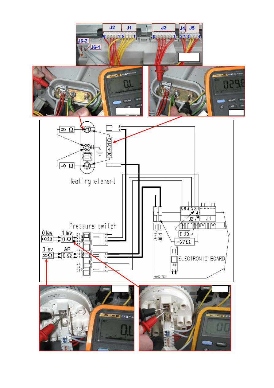
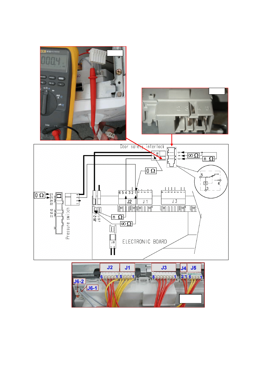
E33: Incongruence between contact closure of anti-boiling and 1st level contacts of
pressure switch
E33
The anti-boiling contact is open while the 1st level contact is closed, or other incongruence
between the pressure switch levels for more than 3 seconds
E33
Tests to be performed:
Replace the connector. Start the
diagnostics cycle and select
phase 6
(water fill to 1st level followed by heating).
Two “clicks” should be heard from the
pressure switch. Measure directly on the
pressure switch.
DO NOT DETACH THE TUBE.
Is the circuit between contacts 11-24 and
21-24 closed?
- fig. 3 -
Replace the pressure
switch and restart the
diagnostics cycle to
check for further alarm
conditions.
Replace the heating
element and restart
the diagnostics
cycle to check for
further alarm
conditions.
Measure the ohmic resistance of the
heating element (
Ω) across terminals J2-1
and J6-1 on the wiring connector.
-see fig.1-
.
Is the resistance correct?
(26
÷28Ω for 230V/1950W,
28
÷31Ω for 240V/1950W)
Replace the circuit board and restart the
diagnostics cycle to check for further
alarm conditions.
Replace the heating
element and restart the
diagnostics cycle to check
for further alarm
conditions.
If there are traces of
burning on the circuit
board, refer to pages 62-64
This fault may be caused by the heating
element which, if the insulation becomes
detached, may send unusual signals to
the circuit board. Generally, this fault
occurs when the heating element is hot.
Restart the diagnostics cycle (
phase 6
)
and wait for about 2-4 minutes. Switch off
the appliance and check for possible
current leakage (fig. 15). Is the heating
element OK?
Replace the wiring and
restart the diagnostics
cycle to check for further
alarm conditions.
Check the wiring between terminals J2-1
and J2-2 of the connector (circuit board
side)
-see fig.1-
.
Is the circuit closed?
Replace the pressure
switch and restart the
diagnostics cycle to check
for further alarm
diti
Drain the water from the tub. Is the circuit
between contacts 11 – 14 and 21 – 24 of
the pressure switch open?
- fig. 3a -
Measure the ohmic
resistance directly on the
terminals of the heating
element (detach the
connectors)
-see fig.13-
.
Is the resistance correct?
26
÷28Ω for 230V/1950W
28
÷31Ω for 240V/1950W
2002-03 SOI/DT-eb LPD/C&F-hd PLT/ASQ-apdv
25
599 35 16-00
E33
fig. 3
fig. 1
fig. 15
fig. 13
fig. 3a
2002-03 SOI/DT-eb LPD/C&F-hd PLT/ASQ-apdv
26
599 35 16-00
NO
NO
NO
YES
NO
NO
YES
NO
YES
YES
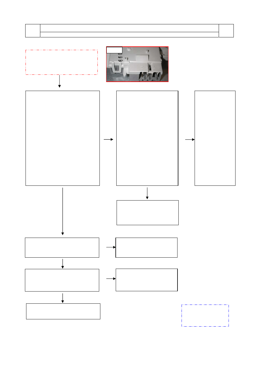
E35: Water level too high
E35
The anti-overflow safety pressure switch is on “FULL” for more than 15 seconds
(if featured)
E35
Tests to be performed:
Replace the fill
solenoid and
restart the
diagnostics cycle to
check for further
alarm conditions.
Start the
diagnostics
cycle from
phase 8
. After
closing the door,
does the water
fill continue?
Is the wiring OK?
Measure across J2-3
and J2-6 for closed
circuit if connected
across 31-32 of the
pressure switch
(open circuit if
connected across 31-
34 of the pressure
switch)
Do the contacts of
the pressure
switch close
correctly? Without
water, contact 31-
32 closed (31-34,
if featured, open).
Replace the circuit
board and restart
the diagnostics
cycle to check for
further alarm
conditions.
Replace the
pressure switch
and restart the
diagnostics
cycle to check
for further alarm
conditions.
YES
Does the
appliance fill with
water even when
switched off?
Repair or replace
the wiring and
restart the
diagnostics cycle to
check for further
alarm conditions.
Start the diagnostics cycle from
phase 2
and
fill with water up to the porthole door. Does the
pressure switch close the 1st level contacts?
(21-24 closed)
Yes
Replace the pressure switch and restart the
diagnostics cycle to check for further alarm
conditions.
Reconnect the wiring to the pressure switch. Is
the wiring efficient?
Measure across connector J2-1 and J2-2
(circuit closed) -
fig.1
-
Repair and/or replace the wiring and restart
the diagnostics cycle to check for further alarm
conditions.
Replace the circuit board and restart the
diagnostics cycle to check for further alarm
conditions.
If there are traces of
burning on the circuit
board, refer to pages
62-64
2002-03 SOI/DT-eb LPD/C&F-hd PLT/ASQ-apdv
27
599 35 16-00
E35
Tub empty
Water at 1st level
E36
E36: «sensing» circuit of anti-boiling pressure switch faulty
E36
Tests to be performed:
E37
E37: «sensing» circuit of 1st level pressure switch faulty
E37
Tests to be performed:
E39
E39: “HV” «sensing» circuit of anti-overflow pressure switch faulty
E39
Tests to be performed:
Replace the circuit board and restart the diagnostics cycle to check for further alarm conditions.
Replace the circuit board and restart the diagnostics cycle to check for further alarm conditions.
Replace the circuit board and restart the diagnostics cycle to check for further alarm conditions.
If there are traces of burning on the
circuit board, refer to pages 62-64
fig. 1
2002-03 SOI/DT-eb LPD/C&F-hd PLT/ASQ-apdv
28
599 35 16-00
NO
Is the door correctly
closed?
YES
YES
NO
NO
NO
YES
YES
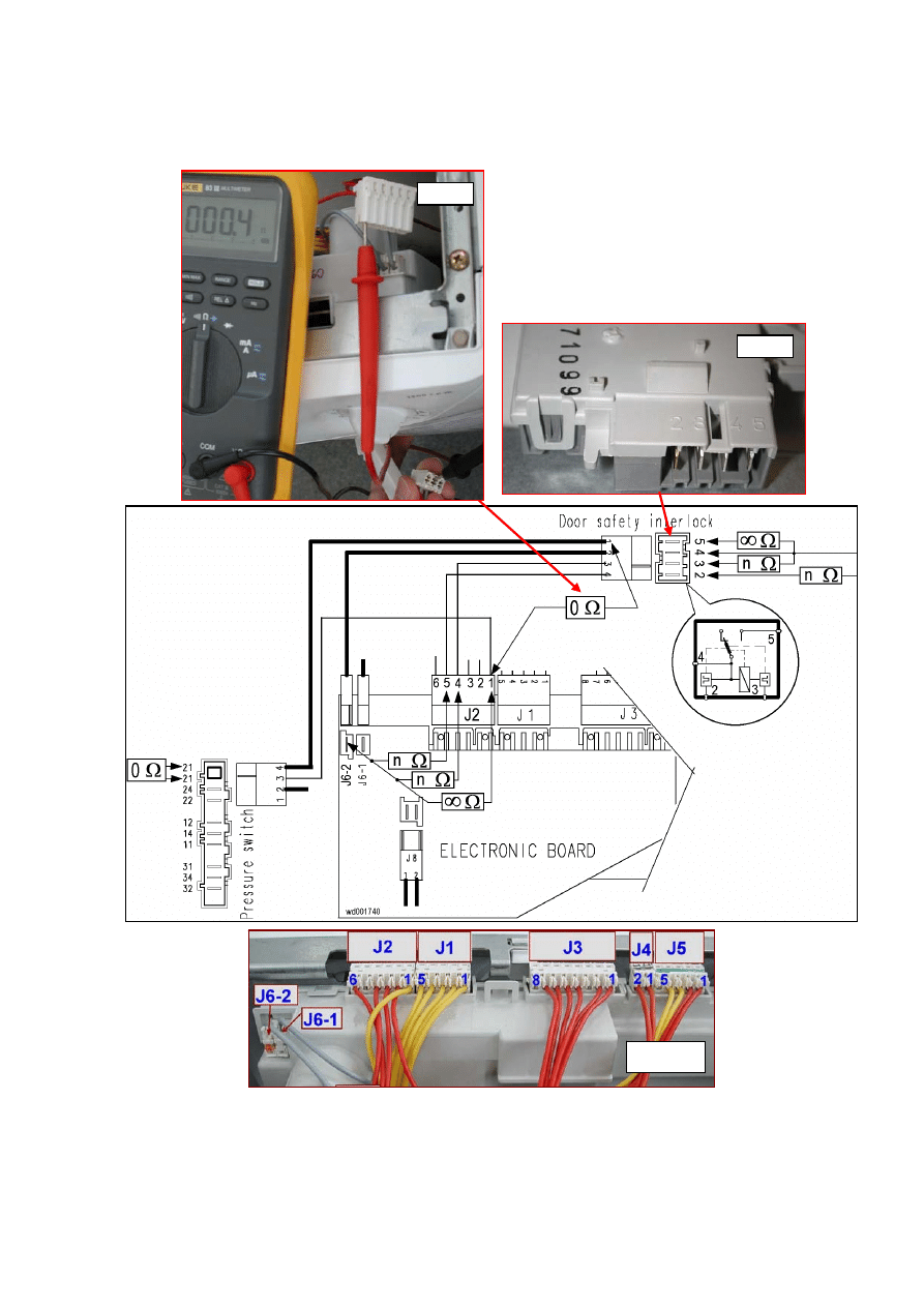
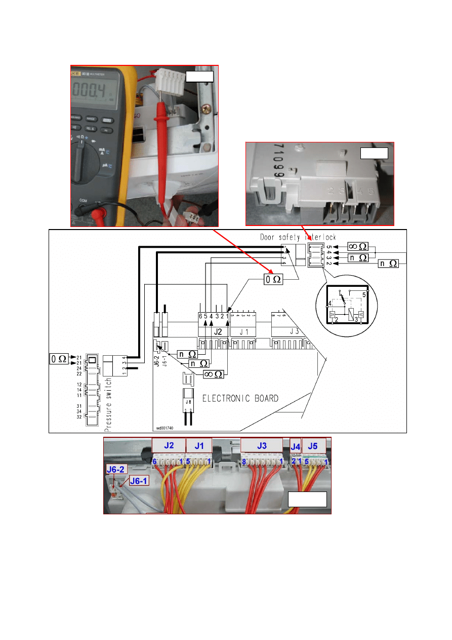
E41: Door open (section 1: device with 3 contacts)
E41
Maximum time exceeded (PTC = 15 seconds, instantaneous, 3 attempts every 2 seconds)
E41
Tests to be performed:
YES
Detach the connectors and
effect measurement on the
component (
fig 6
):
- across connectors 3 and 5,
the circuit must NOT be
open (the resistive value
should be measurable);
- across connectors 4 and 5,
the circuit must be OPEN
(the numbers are printed on
the component).
Is the door safety interlock
OK?
3 Contacts
Traditional door interlock
- fig. 6 -
To check the wiring (with the door
open), measure the following
wiring connectors:
- between wires J2-4 and J6-2, the
circuit must NOT be open
(measure the resistive value of the
PTC);
- between wires J6-2 and J2-1, the
circuit must be OPEN.
- between connector J2-1 (PCB
side) and the wire to connector 4
of the door interlock (
fig. 7
), the
circuit must be CLOSED.
Is the system OK?
Replace the door
interlock and
restart the
diagnostics cycle
to check for
further alarm
conditions.
Check/replace the wiring and
restart the diagnostics cycle to
check for further alarm
conditions.
Replace the door locking device.
Does the appliance function
correctly?
Is the door locking device securely
anchored to the latch?
NO
Close the door correctly
and restart the diagnostics
cycle to check for further
alarm conditions.
Does the door
inter-lock
have 3 or 4
connectors?
4 Connectors
(Instantaneous door
interlock)
-fig. 8, see page 30 -
YES
Replace the door latch or the
door
Replace the circuit board and
restart the diagnostics cycle to
check for further alarm
conditions.
Restart the diagnostics cycle to
check for further alarm conditions.
fig. 6
If there are traces of
burning on the circuit
board, refer to pages
62-64
2002-03 SOI/DT-eb LPD/C&F-hd PLT/ASQ-apdv
29
599 35 16-00
E41a
fig. 6
fig. 1
fig. 7
2002-03 SOI/DT-eb LPD/C&F-hd PLT/ASQ-apdv
30
599 35 16-00
NO
NO
YES
YES
NO
NO
YES
YES
E41: Problems with aperture of door (section 2 – device with 4 connectors)
E41
Maximum time exceeded (255 seconds for version with PTC / 5 impulses for instantaneous)
E41
Tests to be performed:
Detach the connectors from
the door locking device and
measure the following on
the component:
- between connectors 3 and
4 the circuit must NOT be
open (measure the resistive
value of the PTC).
- between connectors 2 and
4 the circuit must NOT be
open (measure the resistive
value of the PTC).
- between connectors 4 and
5 the circuit must be OPEN
(the numbers are marked on
the component.
Is the door lock OK?
(fig. 8)
4 Connections
Instantaneous door locking
device
- fig 8 -
To check the wiring (with the door
open), measure the following
wiring contacts (
fig. 1
):
- between wires J2-5 and J6-2, the
circuit must NOT be open
(measure the resistive value of the
PTC);
- between wires J2-4 and J6-2, the
circuit must NOT be open
(measure the resistive value of the
PTC).
- between wires J2-1 and J6-2, the
circuit must be OPEN.
- between J2-1 and the wire to
connector 5 on the door lock there
must be a short-circuit.
Is the system OK?
Replace the door
locking device
and restart the
diagnostics cycle
to check for
further alarm
conditions.
Check/replace the wiring and
restart the diagnostics cycle to
check for further alarm
conditions.
Replace the door locking device.
Does the appliance function
correctly?
Is the door locking device securely
anchored to the latch?
Replace the door latch or the
door
Replace the circuit board and
restart the diagnostics cycle to
check for further alarm
conditions.
Restart the diagnostics cycle to
check for further alarm conditions.
YES
If there are traces of
burning on the circuit
board, refer to pages.
62-64
fig. 8
2002-03 SOI/DT-eb LPD/C&F-hd PLT/ASQ-apdv
31
599 35 16-00
E41b
fig. 8
fig. 1
fig. 7
2002-03 SOI/DT-eb LPD/C&F-hd PLT/ASQ-apdv
32
599 35 16-00
NO
YES
YES
NO
NO
NO
YES
YES
E42: Problems with aperture of the door (section 1 – device with 3 contacts)
E42
Maximum time exceeded (255 seconds for version with PTC / 5 impulses for instantaneous)
E42
Tests to be performed:
Detach the connectors and
effect measurement on the
component (
fig 6
):
- across connectors 3 and 5,
the circuit must NOT be
open (the resistive value
should be measurable);
- across connectors 4 and 5,
the circuit must be OPEN
(the numbers are printed on
the component).
Is the door safety interlock
OK?
3 Connections
Traditional door locking
device.
- fig. 6 -
To check the wiring (with the door
open), measure the following
wiring connectors (
fig. 1
):
- between wires J2-4 and J6-2, the
circuit must NOT be open
(measure the resistive value of the
PTC);
- between wires J6-2 and J2-1, the
circuit must be OPEN.
- between connector J2-1 (PCB
side) and the wire to connector 4
of the door interlock (
fig. 7
), the
circuit must be CLOSED).
Is the system OK?
Replace the door
interlock and
restart the
diagnostics cycle
to check for
further alarm
conditions.
Check/replace the wiring and
restart the diagnostics cycle to
check for further alarm
conditions.
Replace the door locking device.
Does the appliance function
correctly?
Is the door locking device securely
anchored to the latch?
Does the door
interlock have
3 or 4
connectors?
4 Connectors
(Instantaneous door
interlock)
-fig. 8, see page 30 -
YES
Replace the door latch or the
door
Replace the circuit board and
restart the diagnostics cycle to
check for further alarm
conditions.
Restart the diagnostics cycle to
check for further alarm conditions.
If there are traces of
burning on the
circuit board, refer
to pages 62-64
fig. 6
2002-03 SOI/DT-eb LPD/C&F-hd PLT/ASQ-apdv
33
599 35 16-00
E42a
fig. 6
fig. 1
fig. 7
2002-03 SOI/DT-eb LPD/C&F-hd PLT/ASQ-apdv
34
599 35 16-00
NO
NO
YES
YES
NO
NO
YES
YES
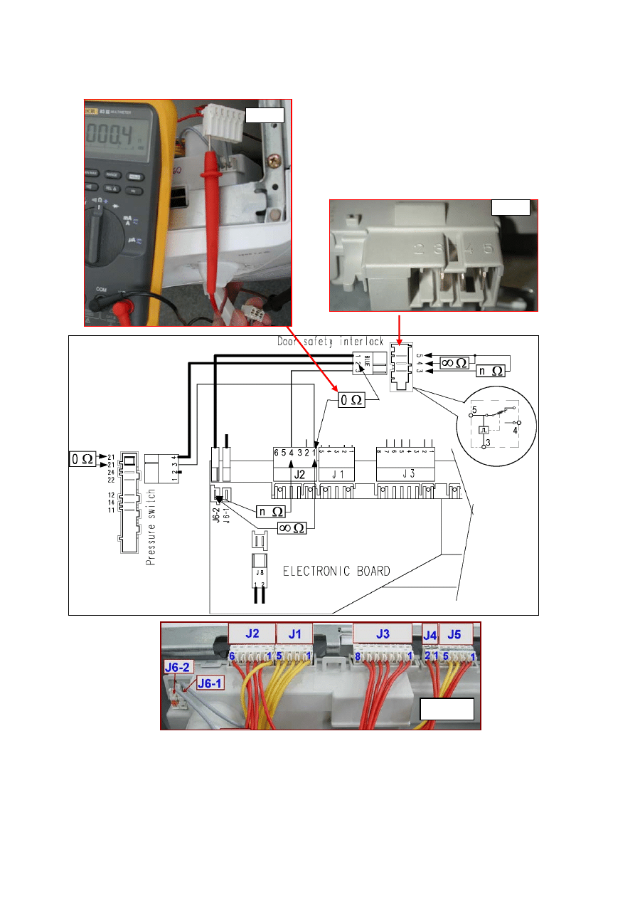
E42: Problems with aperture of the door (section 2 – device with 4 contacts)
E42
Maximum time exceeded (255 seconds for version with PTC / 5 impulses for instantaneous)
E42
Tests to be performed:
Detach the connectors from
the door locking device and
measure the following on
the component:
- between connectors 3 and
4 the circuit must NOT be
open (measure the resistive
value of the PTC).
- between connectors 2 and
4 the circuit must NOT be
open (measure the resistive
value of the PTC).
- between connectors 4 and
5 the circuit must be OPEN
(the numbers are marked on
the component.
Is the door lock OK?
(fig. 8)
4 Connections
Instantaneous door locking
device
- fig 8 -
To check the wiring (with the door
open), measure the following
wiring connectors (
fig. 1
):
- between wires J2-5 and J6-2, the
circuit must NOT be open
(measure the resistive value of the
PTC);
- between wires J2-4 and J6-2, the
circuit must NOT be open
(measure the resistive value of the
PTC).
- between wires J2-1 and J6-2, the
circuit must be OPEN.
- between J2-1 and the wire to
connector 5 on the door lock there
must be a short-circuit.
Is the system OK?
Replace the door
locking device
and restart the
diagnostics cycle
to check for
further alarm
conditions.
Check/replace the wiring and
restart the diagnostics cycle to
check for further alarm
conditions.
Replace the door locking device.
Does the appliance function
correctly?
Is the door locking device securely
anchored to the latch?
Replace the door latch or the
door
Replace the circuit board and
restart the diagnostics cycle to
check for further alarm
conditions.
Restart the diagnostics cycle to
check for further alarm conditions.
YES
If there are traces of
burning on the circuit
board, refer to pages
62-64
fig. 8
2002-03 SOI/DT-eb LPD/C&F-hd PLT/ASQ-apdv
35
599 35 16-00
E42b
fig. 8
fig. 1
fig. 7
2002-03 SOI/DT-eb LPD/C&F-hd PLT/ASQ-apdv
36
599 35 16-00
NO
YES
YES
NO
YES
E43
E43: Problems with the triac which actions the door interlock – section 1
- device with 3 contacts
E43
Tests to be performed:
Detach the connectors and
effect measurement on the
component (
fig 6
):
- across connectors 3 and 5,
the circuit must NOT be
open (the resistive value
should be measurable);
- across connectors 4 and 5,
the circuit must be OPEN
(the numbers are printed on
the component).
Is the door safety interlock
OK?
3 Connectors
Traditional door locking
device.
- fig. 6 -
To check the wiring (with the door
open), measure the following
wiring connectors (
fig. 1
):
- between wires J2-4 and J6-2, the
circuit must NOT be open
(measure the resistive value of the
PTC);
- between wires J6-2 and J2-1, the
circuit must be OPEN (measure
the resistive value of the PTC).
- between connector J2-1 (board
side) and the wire to connector 4
of the door interlock (
fig. 7
), the
circuit must be CLOSED).
Is the system OK?
Replace the door
interlock and
restart the
diagnostics cycle
to check for
further alarm
conditions.
Check/replace the wiring and
restart the diagnostics cycle to
check for further alarm
conditions.
Replace the circuit board and restart
the diagnostics cycle to check for
further alarm conditions.
Does the door
inter-lock
have 3 or 4
connectors?
4 Connectors
(Instantaneous door
interlock)
-fig. 8, see page 30 -
If there are traces of
burning on the circuit
board, refer to pages
62-64
fig. 6
2002-03 SOI/DT-eb LPD/C&F-hd PLT/ASQ-apdv
37
599 35 16-00
E43a
fig. 6
fig. 1
fig. 7
2002-03 SOI/DT-eb LPD/C&F-hd PLT/ASQ-apdv
38
599 35 16-00
NO
NO
YES
YES
YES
E43
E43: Problems with the triac which actions the door interlock – section 2
- device with 4 contacts
E43
Tests to be performed:
Detach the connectors from
the door locking device and
measure the following on
the component:
- between connectors 3 and
4 the circuit must NOT be
open (measure the resistive
value of the PTC).
- between connectors 2 and
4 the circuit must NOT be
open (measure the resistive
value of the PTC).
- between connectors 4 and
5 the circuit must be OPEN
(the numbers are marked on
the component.
Is the door lock OK?
(fig. 8)
4 Connections
Instantaneous door locking
device
- fig 8 -
To check the wiring (with the door
open), measure the following
wiring connectors (
fig. 1
):
- between wires J2-5 and J6-2, the
circuit must NOT be open
(measure the resistive value of the
PTC);
- between wires J2-4 and J6-2, the
circuit must NOT be open
(measure the resistive value of the
PTC).
- between wires J2-1 and J6-2, the
circuit must be OPEN.
- between J2-1 and the wire to
connector 5 on the door lock there
must be a short-circuit (fig. 7).
Is the system OK?
Replace the door
locking device
and restart the
diagnostics cycle
to check for
further alarm
conditions.
Check/replace the wiring and
restart the diagnostics cycle to
check for further alarm
conditions.
Replace the circuit board and restart
the diagnostics cycle to check for
further alarm conditions.
If there are traces of
burning on the circuit
board, refer to pages
62-64
fig. 8
2002-03 SOI/DT-eb LPD/C&F-hd PLT/ASQ-apdv
39
599 35 16-00
E43b
fig. 8
fig. 1
fig. 7

2002-03 SOI/DT-eb LPD/C&F-hd PLT/ASQ-apdv
40
599 35 16-00
E44
E44: Door closure «sensing» circuit faulty
E44
Tests to be performed:
E45
E45: Problems with the «sensing» circuit of the triac that actions the door interlock
E45
Tests to be performed:
Replace the circuit board and restart the
diagnostics cycle to check for further alarm
conditions.
Replace the circuit board and restart the
diagnostics cycle to check for further alarm
conditions.
If there are traces of
burning on the circuit
board, refer to pages
62-64
2002-03 SOI/DT-eb LPD/C&F-hd PLT/ASQ-apdv
41
599 35 16-00
NO
NO
NO
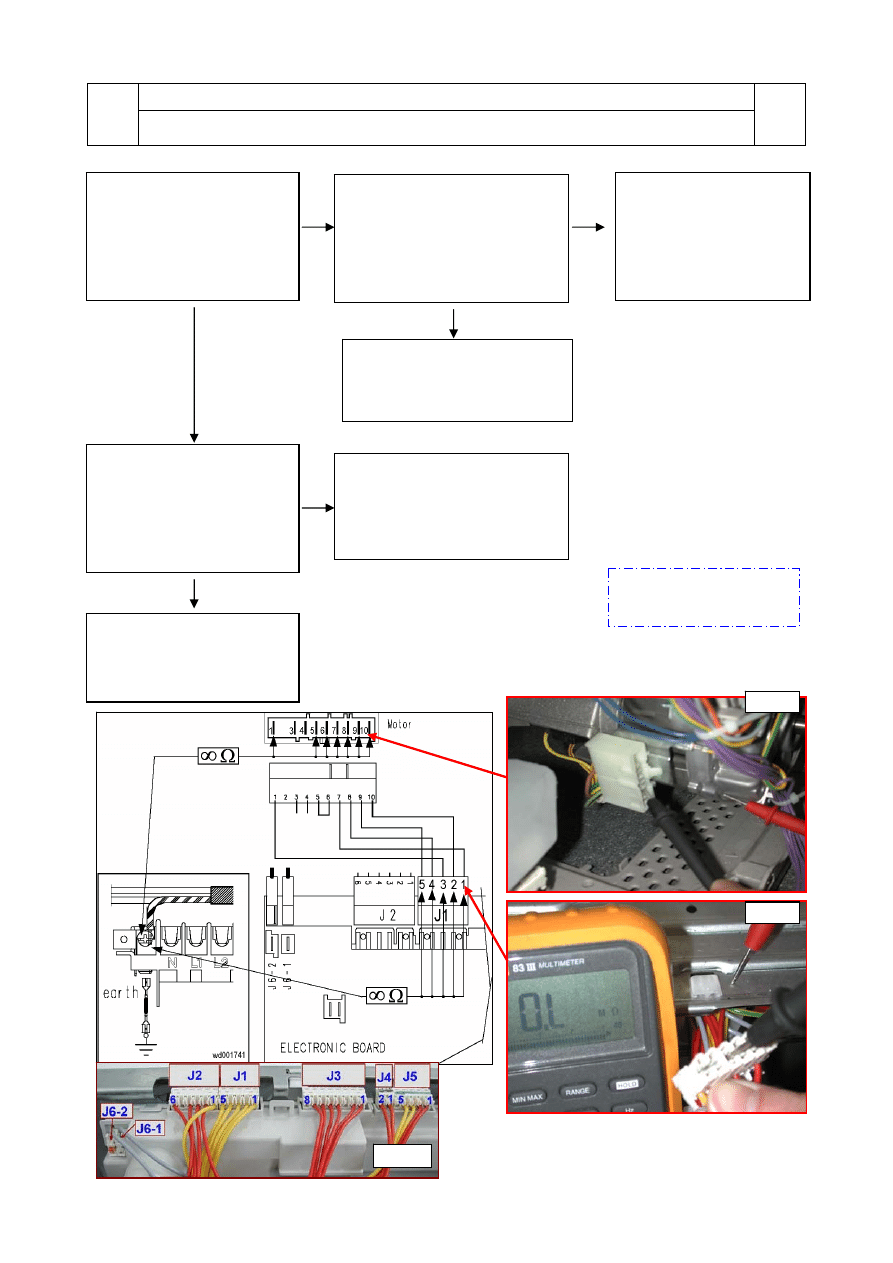
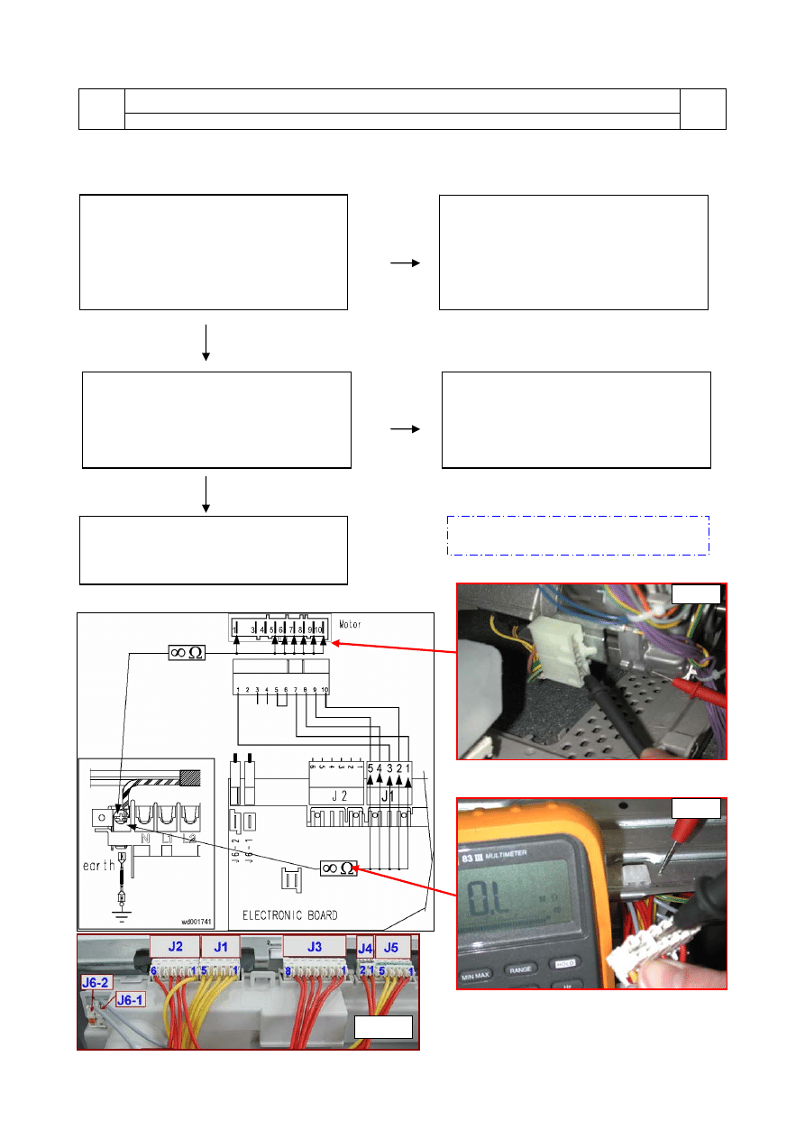
E51: Motor power triac short-circuited
E51
Intervention of the safety system for short-circuiting of the triac (after 5 attempts during the
cycle, immediately if detected at the start or during diagnostics)
E51
Tests to be performed:
fig. 9
YES
YES
YES
Measure between all the
terminals of wiring connector
J1 and the structure of the
appliance
-
see fig. 1 and 9
–
Is there current leakage?
Detach the connector from
the motor and measure
across the terminals of the
motor and the body of the
machine –
see fig. 10
.
Is there current leakage?
Detach connector J1 from the
circuit board and perform
phase 8
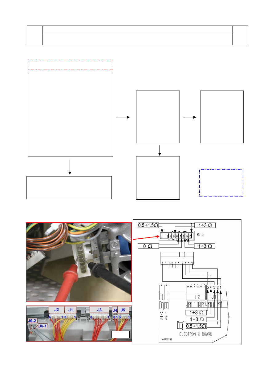
of the diagnostics
cycle.
Is alarm E51 still displayed?
Replace the circuit board and
restart the diagnostics cycle to
check for further alarm
conditions.
Replace the motor and
restart the diagnostics cycle
to check for further alarm
conditions.
Check/replace the wiring and
restart the diagnostics cycle to
check for further alarm
conditions.
fig. 10
E52 will probably be
displayed: replace the
connector and restart the
diagnostics cycle to
check for further alarm
conditions.
If there are traces of
burning on the circuit
board, refer to pages 62-64
fig. 1
2002-03 SOI/DT-eb LPD/C&F-hd PLT/ASQ-apdv
42
599 35 16-00
YES
YES
NO
YES
YES
NO
NO
YES
NO
NO
YES
E52: No signal from the motor tachymetric generator (section 1)
E52
Cycle blocked after 5 attempts during the cycle or immediately if
detected at the start or during
diagnostics
E52
Tests to be performed:
Perform phase 7 of
the diagnostics cycle
(the drum rotates at
50 rpm clockwise and
250 rpm anti-
clockwise). Does the
motor rotate
correctly?
The motor protection
circuit-breaker has
probably tripped.
Before replacing the
motor, check the
following
→ that the hydraulic
circuit of the pressure
switch is OK (minor
leaks from the tube
may cause greater
than normal water
fills, and the motor
may overheat)
→ that the bearings
are OK and the drum
rotates without friction
→ that the mains
voltage is correct (if
the voltage is too low,
though not lower than
the EB3 alarm
threshold, the motor
might not start)
Restart the
diagnostics cycle to
check for further
alarm conditions.
Check/replace the
wiring and restart the
diagnostics cycle to
check for further
alarm conditions.
Replace the
motor or the
tachymetric
generator and
restart the
diagnostics cycle
to check for
further alarm
conditions.
Measure across the
same terminals of the
wiring connector
(J5-3 and J5-4) and
the structure of the
appliance.
Is there any current
leakage?
- see fig.9 -
Is the positioning of
the tachymetric
generator correct?
- see fig.12 -
Replace the main
circuit board and
restart the
diagnostics cycle to
check for further
alarm conditions.
Replace the
motor/
tachymetric
generator and
restart the
diagnostics cycle
to check for
further alarm
conditions.
Check/replace the
wiring and restart the
diagnostics cycle to
check for further
alarm conditions.
Does the
motor rotate
for a few
moments and
then stop?
The motor does not rotate at all
- see page 44 -
NO
Measure across the
terminals of the wiring
connector (J5-3 and
J5-4). Are the values
(
Ω) of the tachymetric
generator correct?
(refer to page 45
- step 4, phase “A” ).
Detach the
connector from the
motor and measure
(
Ω) the coil of the
tachymetric
generator
-see fig.11-
Is the value
correct?
(refer to page 45
- step 4, phase “A”)
If there are
traces of burning
on the circuit
board, refer to
pages 62-64
2002-03 SOI/DT-eb LPD/C&F-hd PLT/ASQ-apdv
43
599 35 16-00
E52a
fig. 10
fig. 11
fig. 12
fig. 9
fig. 1
2002-03 SOI/DT-eb LPD/C&F-hd PLT/ASQ-apdv
44
599 35 16-00
YES
YES
E52: No signal from the tachymetric generator (section 2)
E52
Cycle blocked after 5 attempts during the cycle or immediately if
detected at the start or during
diagnostics
E52
Tests to be performed:
To check the wiring, measure (
Ω -
fig.
11
) across the following terminals of
the circuit board connector (
fig.1
) and
compare with the correct values
(see page 45: step 4 – motor
parameters)
- across J1-1 and J1-2, the value must
be as in
step 4 -
B (Stator)
- across J1-1 and J1-3, if present, the
value must be as in
step 4 - E
(stator ½
range).
-
across J1-4 and J1-5, the value
must be as in
step 4-D (rotor).
Are these values correct?
Replace the circuit board and restart
the diagnostics cycle to check for
further alarm conditions.
Check the motor
as described on
page
45.
Is the motor OK?
The motor does not rotate at all
NO
Replace the motor
and restart the
diagnostics cycle
to check for further
alarm conditions.
NO
Check/replace
the wiring and
restart the
diagnostics cycle
to check for
further alarm
conditions.
fig. 11
If there are traces of
burning on the
circuit board, refer
to pages 62-64
fig. 1
2002-03 SOI/DT-eb LPD/C&F-hd PLT/ASQ-apdv
45
599 35 16-00
Procedure for checking commutator motors
1) Check the connector blocks (wiring)
and check for detached or bent
terminals.
2) Check for traces, residue or deposits
of water or detergent on the motor and
identify the source.
3) Check for windings or other parts that
may be grounded or poorly insulated.
Use a tester with a minimum scale of
40 M
Ω: between each terminal and the
casing, this should read
∞
(fig. 10)
4) Check each winding against the values
shown in the table below
(fig. 11)
.
Terminals on
motor
terminal block
Checks
SOLE
Motor
[
Ω]
F.H.P.
Motor
[
Ω]
CE.SE.T.
Motor
[
Ω]
171 ÷ 196
A
3 - 4
Winding of tachymetric
generator
469 ÷ 540
126 ÷ 147
64 ÷ 73
B
5 - 10
Stator winding (full
range)
1.0 ÷ 2.2
1.0 ÷ 3.0
1.0 ÷ 2.0
C
6 - 7
Overheating breaker
0
0
0
D
8 - 9
Rotor winding
1.5 ÷ 3.0
1.5 ÷ 3.0
1.5 ÷ 3.0
E
1 - 10
Stator winding (half
range, presence of
terminal 1)
0.5 ÷ 1.0
0.5 ÷ 1.5
0.5 ÷ 1.0
N.B.: When checking the rotor winding, the measurement must be effected over the entire surface, rotating
the spindle very slowly and checking for short-circuits between visible plates. Also check the brushes
for wear.
fig. 10
fig. 11
P = motor overload breaker
R = rotor S = stator
= T = tachymetric generator

2002-03 SOI/DT-eb LPD/C&F-hd PLT/ASQ-apdv
46
599 35 16-00
E53
E53: Problems with the «sensing» circuit of the triac which powers the motor
E53
Tests to be performed:
Replace the circuit board and restart the
diagnostics cycle to check for further alarm
conditions.
If there are traces of
burning on the circuit
board, refer to pages 62-64
2002-03 SOI/DT-eb LPD/C&F-hd PLT/ASQ-apdv
47
599 35 16-00
NO
NO
E54: Motor relay contacts sticking
E54
Voltage in the motor circuit even when the motor should be inoperative
E54
Tests to be performed:
YES
Replace the circuit board and restart the
diagnostics cycle to check for further
alarm conditions.
Measure between all terminals of wiring
connector J1 (
fig.1
) and the structure of
the appliance
see page 45, step 3
Is there any current leakage?
-
see fig. 9 -
Detach the connector from the motor and
measure across the terminals of the
motor and the body of the machine
- see fig. 10 -
Is there any current leakage?
Replace the motor and restart the
diagnostics cycle to check for further
alarm conditions.
Check/replace the wiring and restart the
diagnostics cycle to check for further
alarm conditions.
YES
If there are traces of burning on the circuit
board, refer to pages 62-64
fig. 10
fig. 9
fig. 1
2002-03 SOI/DT-eb LPD/C&F-hd PLT/ASQ-apdv
48
599 35 16-00
YES
NO
NO
NO
NO
NO
YES
YES
YES
E61: Insufficient heating during washing
E61
Maximum heating time exceeded
E61
Tests to be performed:
Measure the resistance
directly on the terminals of
the heating element (detach
the connectors).
- see fig.13 -
Is the value correct?
(26
÷28Ω for 230V/1950W,
28
÷31Ω for 240V/1950W)
Measure the value of the
NTC sensor across
J5-1 and J5-2 of the
connector on the circuit
board. Is the value correct?
(between 5.7 and 6.3 K
Ω at
20°C, between 1220 and
1280
Ω at 60°C)
Start the diagnostics cycle
and fill with water up to the
level of the door to close the
pressure switch contact.
Measure the value of the
heating element (
Ω) across
terminals J6-1 e J2-1 of the
wiring connector
-see fig.1-
.
Is the value correct?
(26
÷28Ω for 230V/1950W,
28
÷31Ω for 240V/1950W)
Replace the heating
element and restart the
diagnostics cycle to check
for further alarm
conditions.
Check/replace the wiring and
restart the diagnostics cycle
to check for further alarm
conditions. Otherwise, start a
normal cycle and feel the
temperature directly on the
door.
Detach the connector and
measure the value directly
on the NTC sensor.
Is the value correct?
- see fig. 14 -
(between 5.7 and 6.3 K
Ω at
20°C)
Replace the NTC
temperature sensor and
restart the diagnostics
cycle to check for further
alarm conditions.
Replace the pressure
switch and restart the
diagnostics cycle to check
for further alarm
conditions.
Measure across contacts
11- 14 and across 21-24 of
the pressure switch.
- fig. 3 -
Are both contacts closed?
YES
Replace the circuit board
and restart the diagnostics
cycle to check for further
alarm conditions.
Check/replace the wiring
and restart the diagnostics
cycle to check for further
alarm conditions.
If there are traces of
burning on the circuit
board, refer to pages 62-64
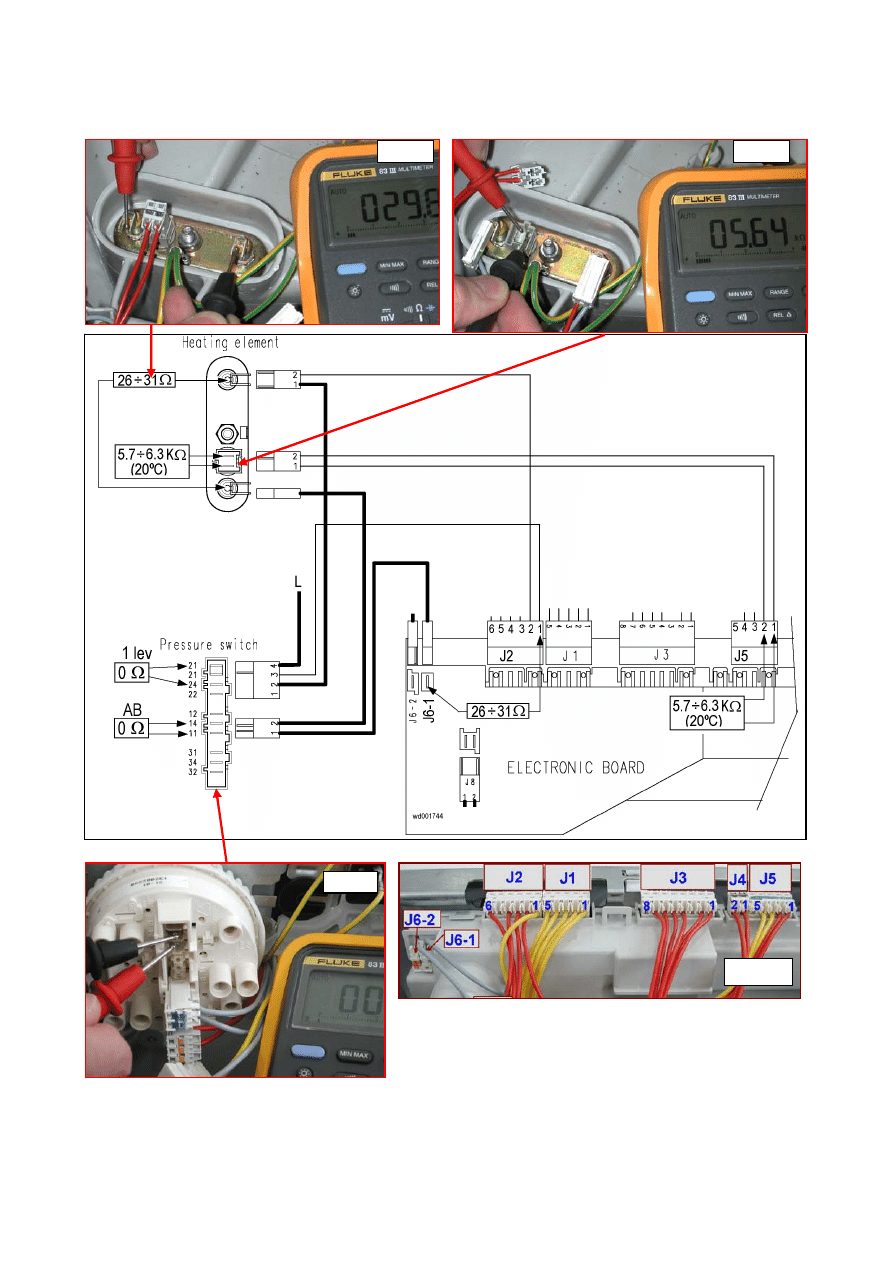
2002-03 SOI/DT-eb LPD/C&F-hd PLT/ASQ-apdv
49
599 35 16-00
E61
fig. 3
fig. 13
fig. 14
fig. 1
2002-03 SOI/DT-eb LPD/C&F-hd PLT/ASQ-apdv
50
599 35 16-00
NO
YES
NO
NO
YES
NO
YES
YES
E62: Overheating during washing
E62
The temperature of the NTC sensor exceeds 88°C for more than 5 minutes
E62
Tests to be performed:
Measure the NTC sensor
across terminals J4-1 and
J4-2 of the circuit board
connector.
Is the value correct?
(between 5.7 and 6.3 K
Ω at
20°C)
Start the diagnostics cycle
and fill with water up to the
level of the door to close the
pressure switch contact.
Measure between wiring
connector J2-2 (
fig.1
) and
the structure of the
appliance.
- see fig. 9 -
Is the circuit open?
Detach the connector and
measure across the heating
element and the ground
contact.
- see fig. 15 -
Is the circuit open?
Replace the heating
element and restart the
diagnostics cycle to check
for further alarm
conditions.
Check/replace the wiring
and restart the diagnostics
cycle to check for further
alarm conditions.
Measurement across J2-2
and the structure of the
appliance may be repeated
after replacing the heating
element connectors.
Detach the connector and
measure directly on the
NTC sensor
- see fig. 14 -
Is the value correct?
(between 5.7 and 6.3 K
Ω at
20°C)
Replace the NTC sensor
and restart the diagnostics
cycle to check for further
alarm conditions.
Replace the circuit board
and restart the diagnostics
cycle to check for further
alarm conditions.
Check/replace the wiring
and restart the diagnostics
cycle to check for further
alarm conditions.
If there are traces of
burning on the circuit
board, refer to pages 62-64
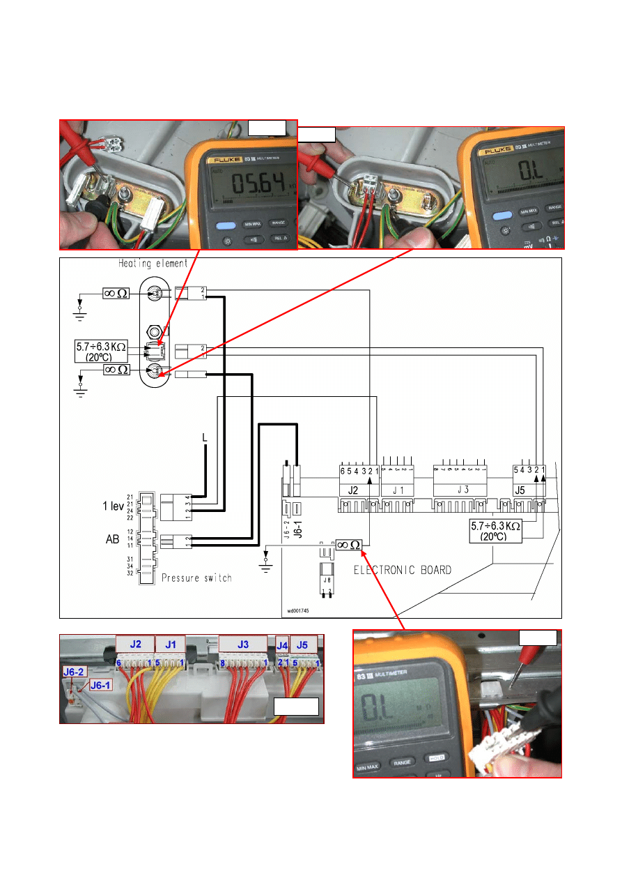
2002-03 SOI/DT-eb LPD/C&F-hd PLT/ASQ-apdv
51
599 35 16-00
E62
fig. 9
fig. 1
fig. 15
fig. 14
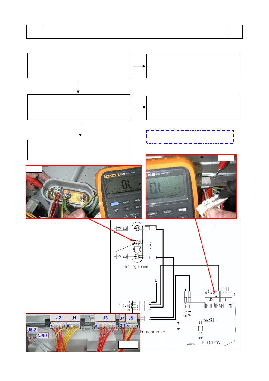
2002-03 SOI/DT-eb LPD/C&F-hd PLT/ASQ-apdv
52
599 35 16-00
YES
NO
YES
NO
E66
E66: The contacts of the heating element power relay are always closed
E66
Tests to be performed:
Measure across connector J2-2 on the circuit
board and the structure of the appliance
(Fig. 1 and 9)
Is there any current leakage?
Replace the circuit board and restart the
diagnostics cycle to check for further
alarm conditions.
Detach the connector and measure across the
heating element and the ground contact.
- fig. 15 -
Is the circuit open?
Replace the heating element and restart
the diagnostics cycle to check for further
alarm conditions.
Check/replace the wiring and restart the
diagnostics cycle to check for further alarm
conditions.
If there are traces of burning on the circuit
board, refer to pages 62-64
fig. 9
fig. 1
fig. 15
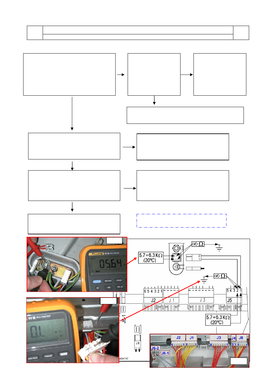
2002-03 SOI/DT-eb LPD/C&F-hd PLT/ASQ-apdv
53
599 35 16-00
YES
NO
NO
YES
YES
YES
NO
NO
E71: NTC washing sensor faulty
E71
Voltage not within limits (short-circuited or open)
E71
Tests to be performed:
fig. 1
fig. 9
fig. 14
Perform
phase 6
of the diagnostics cycle
and wait until the fill ends. Switch the
appliance off and measure the value of
the NTC sensor across contacts J5-1
and J5-2 of the wiring connector (
fig. 1
).
Is the value correct?
(between 5.7 and 6.3 K
Ω at 20°C)
Detach the connector
and measure the NTC
sensor directly.
- see fig. 14 -
Is the value correct?
(5.7 - 6.3 K
Ω at 20°C)
Replace the NTC
sensor and restart the
diagnostics cycle to
check for further
alarm conditions.
Measure across terminals J5-1 and J5-2
of the connector and the structure of the
appliance
- see fig. 9 -
Is there any current leakage?
Check/replace the wiring and restart the diagnostics
cycle to check for further alarm conditions.
Detach the connector and measure directly
across the terminals of the NTC sensor and
the structure of the appliance (there must
be water in the tub).
Is there any leakage?
Replace the NTC sensor and restart the
diagnostics cycle to check for further
alarm conditions.
Replace the circuit board and restart the
diagnostics cycle to check for further
alarm conditions.
Check/replace the wiring and restart the
diagnostics cycle to check for further
alarm conditions.
If there are traces of burning on the circuit
board, refer to pages 62-64
2002-03 SOI/DT-eb LPD/C&F-hd PLT/ASQ-apdv
54
599 35 16-00
YES
NO
NO
YES
NO
YES
E82: Error in reading the RESET/OFF position of the programme selector
E82
Reading of position “0” of the selector when the appliance is switched on, or configuration
error
E82
Tests to be performed:
E83: Error in reading the programme selector code
E83
Code for the position of the selector not included in configuration data or configuration error
E83
Tests to be performed:
Switch the appliance OFF
(selector position “0”).
Do any LEDs light?
Switch the appliance on and
turn the programme selector
to every position. Wait 10
seconds at each position
before passing to the next
one. Does alarm E82
reappear?
Replace the circuit board
and restart the diagnostics
cycle to check for further
alarm conditions.
Replace the circuit board
and restart the diagnostics
cycle to check for further
alarm conditions.
Restart the diagnostics
cycle to check for further
alarm conditions.
Switch the appliance on and
turn the programme selector
to every position. Wait 10
seconds at each position
before passing to the next
one. Does alarm E83
reappear?
Replace the circuit board
and restart the diagnostics
cycle to check for further
alarm conditions.
Restart the diagnostics
cycle to check for further
alarm conditions.

2002-03 SOI/DT-eb LPD/C&F-hd PLT/ASQ-apdv
55
599 35 16-00
E93: Incorrect machine configuration
E93
Incongruence in configuration values when switching on
E93
Tests to be performed:
E94: Incorrect configuration of washing cycle
E94
Incongruence in configuration values when switching on
E94
Tests to be performed:
E95: Communications error between microprocessor and the programme memory
stored in the board (EEPROM)
E95
Error detected during reading or writing of the EEPROM
E95
Tests to be performed:
E96: Incongruence between control panel version and configuration data
E96
Difference between the configuration data and the data that identify the type of control panel
when the appliance is switched on (vertical or horizontal buttons)
E96
Tests to be performed:
E97: Incongruence between selector version and configuration data
E97
Difference between the configuration data for the programmes and those for recognition of
the selector
E97
Tests to be performed:
Possible configuration error
Replace the circuit board and restart the diagnostics cycle to check for further alarm conditions.
Possible configuration error
Replace the circuit board and restart the diagnostics cycle to check for further alarm conditions.
Replace the circuit board and restart the diagnostics cycle to check for further alarm conditions.
Possible configuration error
Replace the circuit board and restart the diagnostics cycle to check for further alarm conditions.
Possible configuration error
Replace the circuit board and restart the diagnostics cycle to check for further alarm conditions.
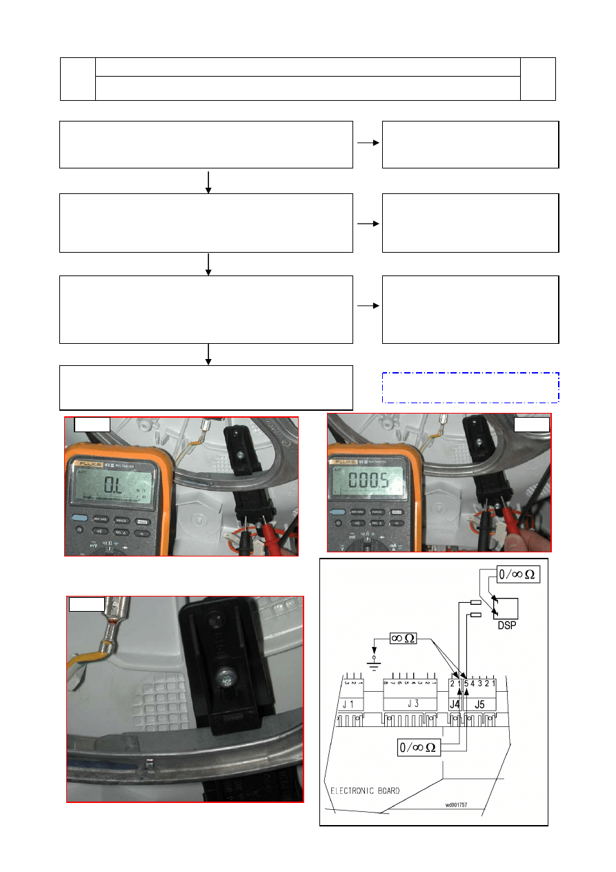
2002-03 SOI/DT-eb LPD/C&F-hd PLT/ASQ-apdv
56
599 35 16-00
NO
NO
NO
EA1: Drum positioning system (DSP) faulty (top-loaders only)
EA1
No signal or discontinuous signal from the sensor for more than 10 seconds during actioning
of the motor to position the drum
EA1
Tests to be performed:
YES
Is the drive belt OK? Is the pulley OK? Is the ferrite plate
positioned correctly?
(
fig. 19
)
Replace the belt/pulley and restart
the diagnostics cycle to check for
further alarm conditions.
If there are traces of burning on the
circuit board, refer to pages 62-64
Remove the connector and measure directly on the sensor:
- circuit closed when on the normal section of the pulley-
(fig. 18)
– circuit open when on the ferrite plate (
fig. 17
). Is
the sensor efficient?
Replace the positioning sensor and
restart the diagnostics cycle to
check for further alarm conditions.
YES
YES
Replace the connector and measure across J5-5 and J4-1
on the wiring connector: when the drum is rotated, the circuit
should open and close. Check for leakage to ground across
the same terminals.
Is the wiring OK?
Check/replace the wiring and restart
the diagnostics cycle to check for
further alarm conditions.
Start the diagnostics cycle (
phase 9
). If alarm EA1
reappears, replace the circuit board and restart the
diagnostics cycle to check for further alarm conditions.
fig. 18
fig. 17
fig. 19
2002-03 SOI/DT-eb LPD/C&F-hd PLT/ASQ-apdv
57
599 35 16-00
YES
NO
NO
YES
NO
YES
EB1: Incorrect mains frequency
EB1
The power supply frequency is not within the configured limits
EB1
Tests to be performed:
EB2: Mains voltage too high
EB2
Mains voltage higher than configured voltage (for more than 10 seconds)
EB2
Tests to be performed:
EB3: Mains voltage too low
EB3
Mains voltage lower than configured voltage
EB3
Tests to be performed:
Is there interference in the power line, or is the
mains frequency outside the correct limits?
Replace the circuit board and restart the
diagnostics cycle to check for further alarm
conditions.
Have the user check and if necessary repair
the domestic power supply circuit.
Important!
The appliance remains in alarm mode until the frequency returns to the correct value or the appliance is
switched off (programme selector on “0”). Only the family of the alarm is displayed, and the diagnostics
cycle cannot be started. The complete alarm can be read only when the alarm condition has ceased.
Is there interference in the power line, or is the
mains voltage outside the correct limits?
Replace the circuit board and restart the
diagnostics cycle to check for further alarm
conditions.
Have the user check and if necessary repair
the domestic power supply circuit.
Important!
The appliance remains in alarm mode until the frequency returns to the correct value or the appliance is
switched off (programme selector on “0”). Only the family of the alarm is displayed, and the diagnostics
cycle cannot be started. The complete alarm can be read only when the alarm condition has ceased.
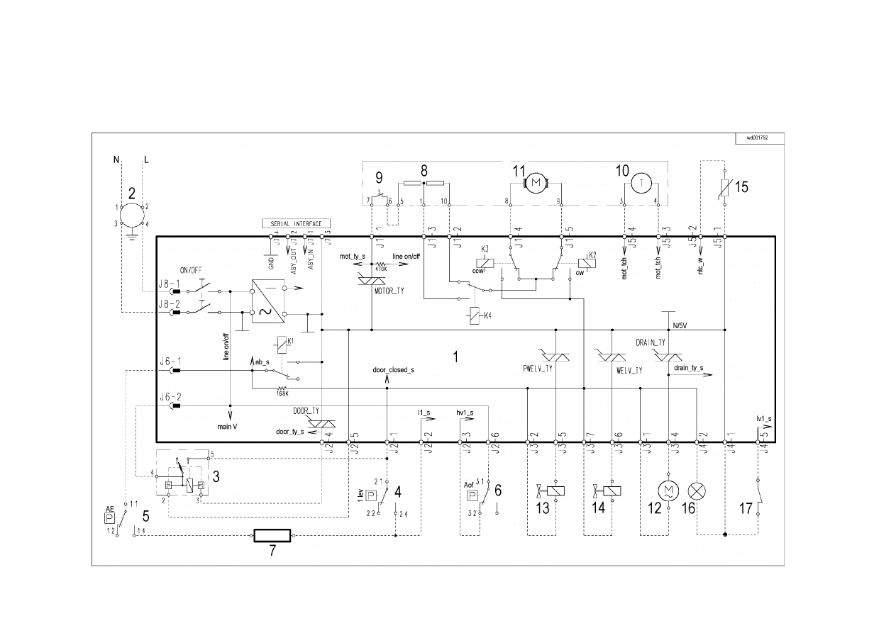
2002-03 SOI/DT-eb LPD/C&F-hd PLT/ASQ-apdv
58
599 35 16-00
6 ELEMENTARY
DIAGRAM
6.1 With instantaneous door locking device
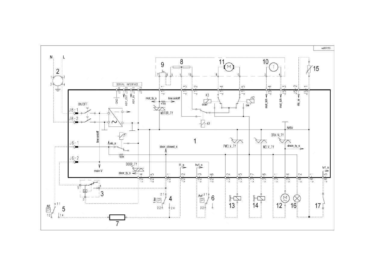
2002-03 SOI/DT-eb LPD/C&F-hd PLT/ASQ-apdv
59
599 35 16-00
6.2 With PTC door locking device

2002-03 SOI/DT-eb LPD/C&F-hd PLT/ASQ-apdv
60
599 35 16-00
6.2.1
Key to circuit diagram
Electrical components – appliance
Components of electronic circuit board
1. Circuit
board
2. Suppressor
3. Main switch (on programme selector)
4. Door safety interlock
5. 1st level pressure switch
6. Anti-boiling pressure switch
7. Anti-overflow pressure switch (certain models only)
8. Heating
element
9. Stator
(motor)
10. Overload circuit-breaker (motor)
11. Tachymetric generator (motor)
12. Rotor (motor)
13. Drain pump
14. Pre-wash solenoid valve
15. Washing solenoid valve
16. “Door closed” lamp (certain models only)
17. Drum positioning system (DSP) (top-loaders – certain models only)
DOOR_TY
Triac for door safety interlock
DRAIN_TY
Triac for drain pump
K1
Heating element relay
K2
Motor relay: clockwise rotation
K3
Motor relay: anti-clockwise rotation
K4
Motor relay: half-range power (certain models only)
MOTOR_TY Motor
triac
ON/OFF
Main switch (programme selector)
PWELW_TY
Triac for pre-wash solenoid valve
Serial interface
Asynchronous serial interface
WELV_TY
Triac for washing solenoid valve
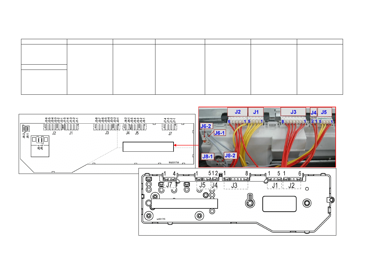
2002-03 SOI/DT-eb LPD/C&F-hd PLT/ASQ-apdv
61
599 35 16-00
7 CONNECTORS ON CIRCUIT BOARD
J6 J2 J1 J3 J4 J5 J7
J6-1: Heating element
(relay)
J6-2: Door safety
interlock (line)
J8
J8-1 line
J8-2 line (neutral)
J2-1 Door safety interlock
(line-sensing)
J2-2 1st level(sensing)
J2-3 (Anti-overflow
pressure switch)
J2-4 Door safety interlock
(triac)
J2-5 (Door safety
interlock)
J2-6 (Anti-overflow
pressure switch)
J1-1 Motor (triac)
J1-2 Motor (stator – full
range)
J1-3 Motor (stator - 1/2
range)
J1-4 Motor (rotor)
J1-5 Motor (rotor)
J3-1 Drain pump (line)
J3-2 Solenoids (line)
J3-3 (line)
J3-4 Drain pump (triac)
J3-5 Pre-wash solenoid
(triac)
J3-6 Washing solenoid
(triac)
J3-7 Solenoids (line)
J3-8 (Not used)
J4-1 “Door closed” pilot
lamp
J4-2 “Door closed” pilot
lamp
J5-1 NTC temperature
sensor
J5-2 NTC temperature
sensor
J5-3 Motor (tachymetric
generator)
J5-4 Motor (tachymetric
generator)
J5-5 (DSP drum
positioning system)
Serial interface:
J7-1 ASY_IN
J7-2 ASY_OUT
J7-3 5V
J7-4 GND
Rear view
Front view
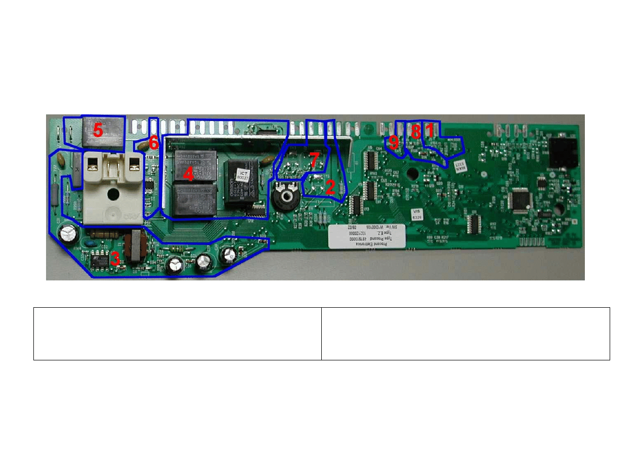
2002-03 SOI/DT-eb LPD/C&F-hd PLT/ASQ-apdv
62
599 35 16-00
8 BURNING ON THE CIRCUIT BOARD
In case of burning on the main circuit board, check that the problem is not caused by another electrical component (short-circuits, poor insulation, water leakage). Refer
to the figures below in order to identify the component that might have caused the burning according to the position of the burned area.
The circuit board shown below is the version with the greatest number of components: other boards may not feature all these components (relay K4 and buzzer).
8.1 COMPONENTS SIDE (common)
1. NTC washing temperature sensor
2. Drain
pump
3. Power
supply
4. Motor
5. Heating
element
6. Door safety interlock
7. Water fill solenoids
8. Tachymetric
generator
(motor)
9. Drum positioning system (top-loaders)
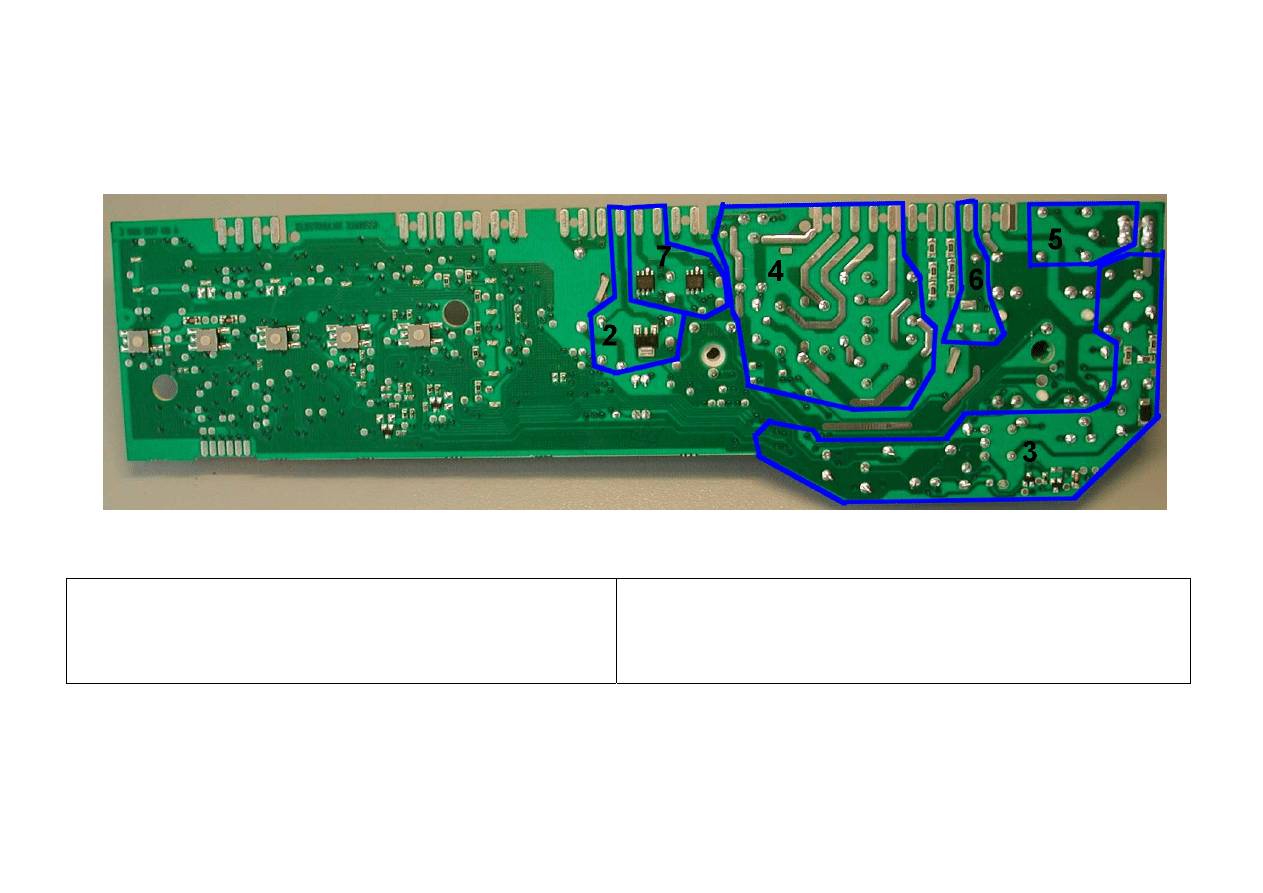
2002-03 SOI/DT-eb LPD/C&F-hd PLT/ASQ-apdv
63
599 35 16-00
8.2 PUSHBUTTON – LED SIDE (HORIZONTAL BUTTONS)
1. ---
2. Drain
pump
3. Power
supply
4. Motor
5. Heating
element
6. Door safety interlock
7. Water fill solenoids
8. Tachymetric
generator
(motor)
9. Drum positioning system (top-loaders)
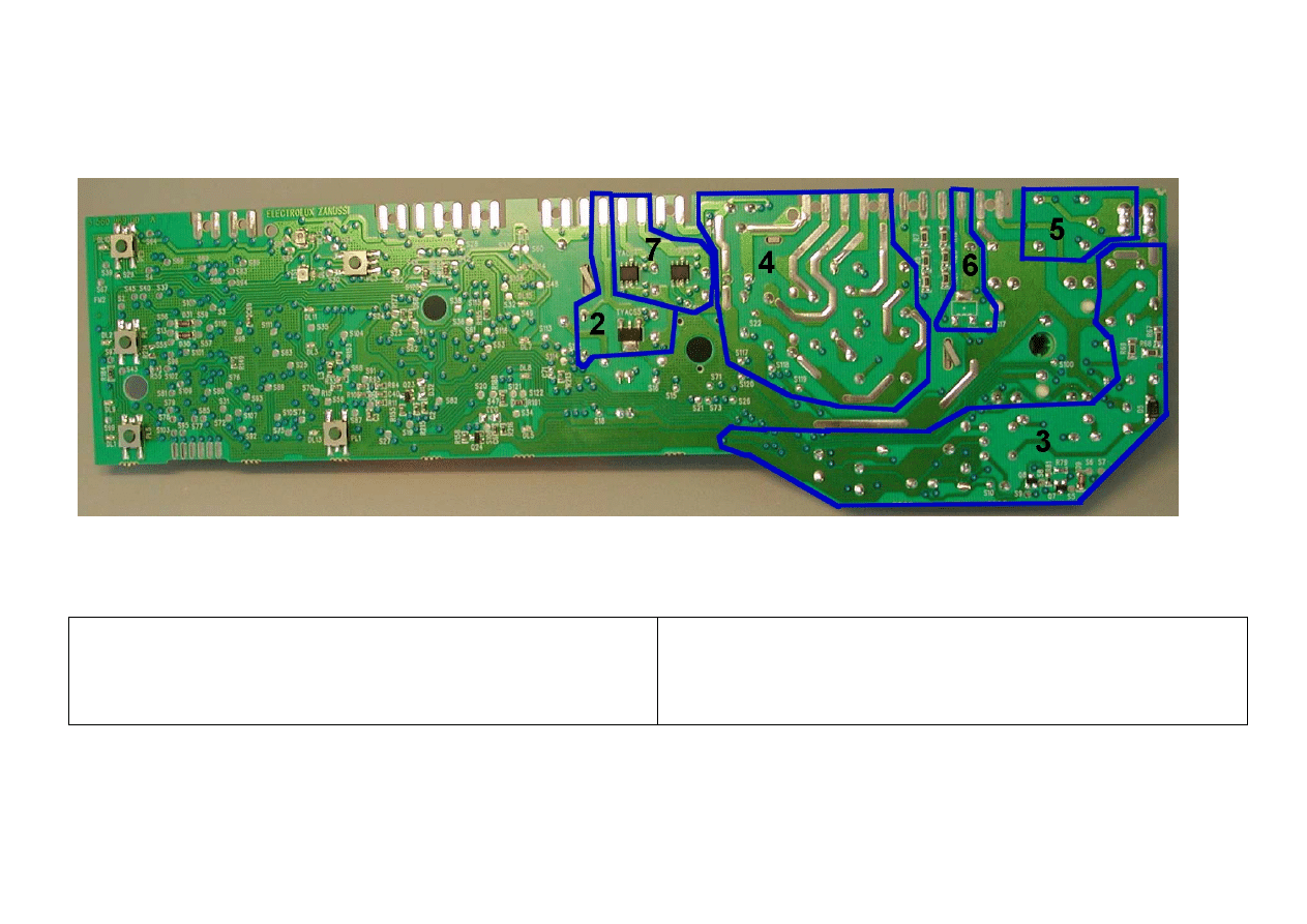
2002-03 SOI/DT-eb LPD/C&F-hd PLT/ASQ-apdv
64
599 35 16-00
8.3 PUSHBUTTON – LED SIDE (VERTICAL BUTTONS)
1. ---
2. Drain
pump
3. Power
supply
4. Motor
5. Heating
element
6. Door safety interlock
7. Water fill solenoids
8. Tachymetric
generator
(motor)
9. Drum positioning system (top-loaders)
Wyszukiwarka
Podobne podstrony:
Elektrolux EWF
Elektronika na kierownicy, SerwisRoweru
INSTRUKCJA BHP DOTYCZĄCA SERWISU ELEKTRONICZNEGO, instrukcje BHP
OPIS DO SERWISU ELEKTRPNIKI 10 99 DO 12 00
Serwis elektroniczny, Instrukcje-Bezpiecznej Pracy
11-serwis elektroniczny, Instrukcje BHP, VII - ELEKTRYKA
INSTRUKCJA BHP DOTYCZĄCA SERWISU ELEKTRONICZNEGO, instrukcje BHP
Jak podłączyć kartę microSD do mikrokontrolera – Serwis Elektroniki
Numer 10 2012 Auto Moto Serwis wersja elektroniczna PDF e czasopismo pl Czasopisma dla Fachowców
Napęd Elektryczny wykład
Podstawy elektroniki i miernictwa2
elektryczna implementacja systemu binarnego
urządzenia elektrotermiczn
Podstawy elektroniki i energoelektroniki prezentacja ppt
Elektryczne pojazdy trakcyjne
więcej podobnych podstron