
OUTLINE DIMENSION
A-1
OD-100330
www.richtek.com
z
z
z
z
zSOT
SOT-143 --------------------------------------------------------------------------------------------------------------------------------- A5
SOT-23-3 -------------------------------------------------------------------------------------------------------------------------------- A6
SOT-23-5 -------------------------------------------------------------------------------------------------------------------------------- A7
SOT-23-6 -------------------------------------------------------------------------------------------------------------------------------- A8
SOT-23-8 -------------------------------------------------------------------------------------------------------------------------------- A9
SOT-89 ---------------------------------------------------------------------------------------------------------------------------------- A10
SOT-89-5 -------------------------------------------------------------------------------------------------------------------------------- A11
SOT-223 --------------------------------------------------------------------------------------------------------------------------------- A12
SOT-223-5 ------------------------------------------------------------------------------------------------------------------------------ A13
SOT-563 --------------------------------------------------------------------------------------------------------------------------------- A14
z
z
z
z
zTSOT
TSOT-23-3 ------------------------------------------------------------------------------------------------------------------------------ A15
TSOT-23-5 ------------------------------------------------------------------------------------------------------------------------------ A16
TSOT-23-6 ------------------------------------------------------------------------------------------------------------------------------ A17
TSOT-23-8 ------------------------------------------------------------------------------------------------------------------------------ A18
z
z
z
z
zTO
TO-92 ------------------------------------------------------------------------------------------------------------------------------------ A19
TO-251 ----------------------------------------------------------------------------------------------------------------------------------- A20
TO-252 ----------------------------------------------------------------------------------------------------------------------------------- A21
TO-252-4 -------------------------------------------------------------------------------------------------------------------------------- A22
TO-252-5 -------------------------------------------------------------------------------------------------------------------------------- A23
TO-263 ----------------------------------------------------------------------------------------------------------------------------------- A24
TO-263-5 -------------------------------------------------------------------------------------------------------------------------------- A25
TO-263S-5 ------------------------------------------------------------------------------------------------------------------------------ A26
TO-263-7 -------------------------------------------------------------------------------------------------------------------------------- A27
TO-220 ----------------------------------------------------------------------------------------------------------------------------------- A28
TO-220-5 -------------------------------------------------------------------------------------------------------------------------------- A29
z
z
z
z
zSOP/DIP
SOP-8 ----------------------------------------------------------------------------------------------------------------------------------- A30
SOP-14 ---------------------------------------------------------------------------------------------------------------------------------- A31
SOP-16 ---------------------------------------------------------------------------------------------------------------------------------- A32
SOP-20 ---------------------------------------------------------------------------------------------------------------------------------- A33
SOP-24 ---------------------------------------------------------------------------------------------------------------------------------- A34
SOP-24 (236mil) ---------------------------------------------------------------------------------------------------------------------- A35
SOP-28 ---------------------------------------------------------------------------------------------------------------------------------- A36
SOP-32 ---------------------------------------------------------------------------------------------------------------------------------- A37
SOP-8 (Exposed Pad) --------------------------------------------------------------------------------------------------------------- A38
DIP-8 ------------------------------------------------------------------------------------------------------------------------------------- A39
DIP-16 ----------------------------------------------------------------------------------------------------------------------------------- A40

OUTLINE DIMENSION
A-2
OD-100330
www.richtek.com
z
z
z
z
zSSOP
SSOP-16 -------------------------------------------------------------------------------------------------------------------------------- A41
SSOP-24 -------------------------------------------------------------------------------------------------------------------------------- A42
SSOP-28 -------------------------------------------------------------------------------------------------------------------------------- A43
SSOP-30 -------------------------------------------------------------------------------------------------------------------------------- A44
z
z
z
z
zTSSOP
TSSOP-8 -------------------------------------------------------------------------------------------------------------------------------- A45
TSSOP-14 ------------------------------------------------------------------------------------------------------------------------------ A46
TSSOP-16 ------------------------------------------------------------------------------------------------------------------------------ A47
TSSOP-20 ------------------------------------------------------------------------------------------------------------------------------ A48
TSSOP-24 ------------------------------------------------------------------------------------------------------------------------------ A49
TSSOP-28 ------------------------------------------------------------------------------------------------------------------------------ A50
TSSOP-32 ------------------------------------------------------------------------------------------------------------------------------ A51
TSSOP-14 (Exposed PAD) --------------------------------------------------------------------------------------------------------- A52
TSSOP-16 (Exposed PAD) --------------------------------------------------------------------------------------------------------- A53
TSSOP-24 (Exposed PAD) --------------------------------------------------------------------------------------------------------- A54
TSSOP-28 (Exposed PAD) --------------------------------------------------------------------------------------------------------- A55
z
z
z
z
zMSOP
MSOP-8 --------------------------------------------------------------------------------------------------------------------------------- A56
MSOP-10 ------------------------------------------------------------------------------------------------------------------------------- A57
MSOP-8 (Exposed PAD) ------------------------------------------------------------------------------------------------------------ A58
MSOP-10 (Exposed PAD) ---------------------------------------------------------------------------------------------------------- A59
z
z
z
z
zSC
SC-70-3 ---------------------------------------------------------------------------------------------------------------------------------- A60
SC-70-4 ---------------------------------------------------------------------------------------------------------------------------------- A61
SC-70-5 ---------------------------------------------------------------------------------------------------------------------------------- A62
SC-70-6 ---------------------------------------------------------------------------------------------------------------------------------- A63
SC-82 ------------------------------------------------------------------------------------------------------------------------------------ A64
z
z
z
z
zSOJ
SOJ-2021-10L -------------------------------------------------------------------------------------------------------------------------- A65
z
z
z
z
zVQFN
VQFN-3x3-16L ------------------------------------------------------------------------------------------------------------------------- A66
VQFN-4x4-16L ------------------------------------------------------------------------------------------------------------------------- A67
VQFN-4x4-20L ------------------------------------------------------------------------------------------------------------------------- A68
VQFN-4x4-24L ------------------------------------------------------------------------------------------------------------------------- A69
VQFN-5x5-16L ------------------------------------------------------------------------------------------------------------------------- A70
VQFN-5x5-24L ------------------------------------------------------------------------------------------------------------------------- A71
VQFN-5x5-28L ------------------------------------------------------------------------------------------------------------------------- A72
VQFN-5x5-32L ------------------------------------------------------------------------------------------------------------------------- A73
VQFN-6x6-28L ------------------------------------------------------------------------------------------------------------------------- A74
VQFN-6x6-40L ------------------------------------------------------------------------------------------------------------------------- A75

OUTLINE DIMENSION
A-3
OD-100330
www.richtek.com
z
z
z
z
zVDFN
VDFN-2x2-6L --------------------------------------------------------------------------------------------------------------------------- A76
VDFN-2x2-8L --------------------------------------------------------------------------------------------------------------------------- A77
VDFN-3x3-6L --------------------------------------------------------------------------------------------------------------------------- A78
VDFN-3x3-8L --------------------------------------------------------------------------------------------------------------------------- A79
VDFN-3x3-10L ------------------------------------------------------------------------------------------------------------------------- A80
VDFN-5x6-8L --------------------------------------------------------------------------------------------------------------------------- A81
z
z
z
z
zWQFN
WQFN-2x2-12L ------------------------------------------------------------------------------------------------------------------------ A82
WQFN-3x3-16L ------------------------------------------------------------------------------------------------------------------------ A83
WQFN-3x3-20L ------------------------------------------------------------------------------------------------------------------------ A84
WQFN-4x4-16L ------------------------------------------------------------------------------------------------------------------------ A85
WQFN-4x4-20L ------------------------------------------------------------------------------------------------------------------------ A86
WQFN-4x4-24L ------------------------------------------------------------------------------------------------------------------------ A87
WQFN-4x4-28L ------------------------------------------------------------------------------------------------------------------------ A88
WQFN-4x4-32L ------------------------------------------------------------------------------------------------------------------------ A89
WQFN-5x5-12L ------------------------------------------------------------------------------------------------------------------------ A90
WQFN-5x5-16L ------------------------------------------------------------------------------------------------------------------------ A91
WQFN-5x5-24L ------------------------------------------------------------------------------------------------------------------------ A92
WQFN-5x5-28L ------------------------------------------------------------------------------------------------------------------------ A93
WQFN-5x5-32L ------------------------------------------------------------------------------------------------------------------------ A94
WQFN-5x5-40L ------------------------------------------------------------------------------------------------------------------------ A95
WQFN-6x6-28L ------------------------------------------------------------------------------------------------------------------------ A96
WQFN-6x6-40L ------------------------------------------------------------------------------------------------------------------------ A97
WQFN-6x6-48L ------------------------------------------------------------------------------------------------------------------------ A98
WQFN-7x7-48L ------------------------------------------------------------------------------------------------------------------------ A99
WQFN-7x7-56L ------------------------------------------------------------------------------------------------------------------------ A100
WQFN-2x3-16L ------------------------------------------------------------------------------------------------------------------------ A101
WQFN-3x4-20L ------------------------------------------------------------------------------------------------------------------------ A102
WQFN-3.5x3.5-14L ------------------------------------------------------------------------------------------------------------------- A103
WQFN-4x5-28L ------------------------------------------------------------------------------------------------------------------------ A104
WQFN-6.5x4.5-46L ------------------------------------------------------------------------------------------------------------------- A105
WQFN-1.6x1.6-8L (COL) ------------------------------------------------------------------------------------------------------------ A106
WQFN-2x2-12L (COL) --------------------------------------------------------------------------------------------------------------- A107
WQFN-2x2-14L (COL) --------------------------------------------------------------------------------------------------------------- A108
WQFN-3x3-24L (COL) --------------------------------------------------------------------------------------------------------------- A109
z
z
z
z
zWDFN
WDFN-2x2-6L -------------------------------------------------------------------------------------------------------------------------- A110
WDFN-2x2-8L -------------------------------------------------------------------------------------------------------------------------- A111
WDFN-3x3-6L -------------------------------------------------------------------------------------------------------------------------- A112
WDFN-3x3-8L -------------------------------------------------------------------------------------------------------------------------- A113
WDFN-3x3-8L, 0.5mm Lead Pitch ------------------------------------------------------------------------------------------------ A114

OUTLINE DIMENSION
A-4
OD-100330
www.richtek.com
WDFN-3x3-10L ------------------------------------------------------------------------------------------------------------------------ A115
WDFN-3x3-12L ------------------------------------------------------------------------------------------------------------------------ A116
WDFN-1.6x1.6-6L --------------------------------------------------------------------------------------------------------------------- A117
WDFN-2x3-8L -------------------------------------------------------------------------------------------------------------------------- A118
WDFN-3x2-10L ------------------------------------------------------------------------------------------------------------------------ A119
WDFN-4x3-12L ------------------------------------------------------------------------------------------------------------------------ A120
WDFN-4x3-16L ------------------------------------------------------------------------------------------------------------------------ A121
WDFN-2x2-6SL ------------------------------------------------------------------------------------------------------------------------ A122
z
z
z
z
zXDFN
XDFN-2x2-8L --------------------------------------------------------------------------------------------------------------------------- A123
z
z
z
z
zWLCSP
WL-CSP-0.7x1.35-5B ---------------------------------------------------------------------------------------------------------------- A124
WL-CSP-0.9x1.3-6B ----------------------------------------------------------------------------------------------------------------- A125
WL-CSP-1x2-8B ---------------------------------------------------------------------------------------------------------------------- A126
WL-CSP-1.5x1.5-8B ----------------------------------------------------------------------------------------------------------------- A127
WL-CSP-1.5x1.5-9B ----------------------------------------------------------------------------------------------------------------- A128
WL-CSP-2.05x2.55-20B ------------------------------------------------------------------------------------------------------------- A129
WL-CSP-2.45x1.95-20B ------------------------------------------------------------------------------------------------------------- A130
WL-CSP-2.55x2.05-20B ------------------------------------------------------------------------------------------------------------- A131
WL-CSP-2.45x2.45-25B ------------------------------------------------------------------------------------------------------------- A132
WL-CSP-2.45x2.05-30B ------------------------------------------------------------------------------------------------------------- A133
WL-CSP-2.4x2.4-32B ---------------------------------------------------------------------------------------------------------------- A134

A-5
OD-100330
www.richtek.com
SOT-143 Surface Mount Package
Dimensions In Millimeters
Dimensions In Inches
Symbol
Min Max Min Max
A
0.800 1.200 0.031
0.047
A1 0.050 0.150 0.002 0.006
B
1.200 1.400 0.047 0.055
b
0.300 0.520 0.012 0.020
b1 0.760 0.920 0.030 0.036
C 2.100 2.640 0.083 0.104
D 2.800
3.040
0.110
0.120
e 1.900
0.075
H 0.080 0.150 0.003 0.006
L
0.210 0.410 0.008 0.016
H
A
A1
b1
C
D
B
b
e
L
e

A-6
OD-100330
www.richtek.com
A
b
A1
B
D
C
e
H
L
SOT-23-3 Surface Mount Package
Dimensions In Millimeters
Dimensions In Inches
Symbol
Min Max Min Max
A
0.889
1.295
0.035
0.051
A1 0.000
0.152
0.000
0.006
B
1.397
1.803
0.055
0.071
b
0.356
0.508
0.014
0.020
C
2.591
2.997
0.102
0.118
D
2.692
3.099
0.106
0.122
e
1.803
2.007
0.071
0.079
H 0.080
0.254
0.003
0.010
L 0.300
0.610
0.012
0.024

A-7
OD-100330
www.richtek.com
A
A1
e
b
B
D
C
H
L
SOT-23-5 Surface Mount Package
Dimensions In Millimeters
Dimensions In Inches
Symbol
Min Max Min Max
A
0.889
1.295
0.035
0.051
A1
0.000
0.152
0.000
0.006
B
1.397
1.803
0.055
0.071
b
0.356
0.559
0.014
0.022
C
2.591
2.997
0.102
0.118
D
2.692
3.099
0.106
0.122
e
0.838
1.041
0.033
0.041
H 0.080
0.254
0.003
0.010
L
0.300
0.610
0.012
0.024

A-8
OD-100330
www.richtek.com
A
A1
e
b
B
D
C
H
L
SOT-23-6 Surface Mount Package
Dimensions In Millimeters
Dimensions In Inches
Symbol
Min Max Min Max
A 0.889
1.295
0.031
0.051
A1 0.000
0.152
0.000
0.006
B
1.397
1.803
0.055
0.071
b
0.250
0.560
0.010
0.022
C
2.591
2.997
0.102
0.118
D
2.692
3.099
0.106
0.122
e
0.838
1.041
0.033
0.041
H
0.080
0.254
0.003
0.010
L
0.300
0.610
0.012
0.024

A-9
OD-100330
www.richtek.com
SOT-23-8 Surface Mount Package
Dimensions In Millimeters
Dimensions In Inches
Symbol
Min Max Min Max
A 1.000 1.450 0.039 0.057
A1 0.000 0.150 0.000 0.006
B 1.500 1.700 0.059 0.067
b
0.220 0.500 0.009 0.020
C 2.600
3.000
0.102
0.118
D 2.800
3.000
0.110
0.118
e
0.585 0.715 0.023 0.028
H 0.100 0.220 0.004 0.009
L
0.300 0.600 0.012 0.024
A
A1
B
D
C
H
L
b
e

A-10
OD-100330
www.richtek.com
Dimensions In Millimeters
Dimensions In Inches
Symbol
Min Max Min Max
A
1.397
1.600
0.055
0.063
b
0.356
0.483
0.014
0.019
B
2.388
2.591
0.094
0.102
b1
0.406
0.533
0.016
0.021
C 3.937
4.242
0.155
0.167
C1
0.787
1.194
0.031
0.047
D 4.394 4.597 0.173
0.181
D1 1.397 1.753 0.055 0.069
e
1.448
1.549
0.057
0.061
H
0.356
0.432
0.014
0.017
b
b1
b
H
A
B
D
C
e
e
C1
D1
A
3-Lead SOT-89 Surface Mount Package

A-11
OD-100330
www.richtek.com
A
A
H
e
e
b
b1
b
D
C
B
C1
D1
b1
5-Lead SOT-89 Surface Mount Package
Dimensions In Millimeters
Dimensions In Inches
Symbol
Min Max Min Max
A
1.400
1.600
0.055
0.063
b
0.360
0.508
0.014
0.020
B
2.400 2.600 0.094
0.102
b1
0.406
0.533
0.016
0.021
C 3.937 4.250 0.155 0.167
C1
0.800
1.194
0.031
0.047
D
4.400
4.600
0.173
0.181
D1
1.397
1.700
0.055
0.067
e
1.400 1.600 0.055
0.063
H
0.356
0.430
0.014
0.017

A-12
OD-100330
www.richtek.com
Symbol
Dimensions In Millimeters
Dimensions In Inches
Min Max Min Max
A 1.400 1.800 0.055 0.071
A1 0.020
0.100
0.001
0.004
b
0.600 0.840 0.024 0.033
B 3.300 3.700 0.130 0.146
C 6.700 7.300 0.264 0.287
D 6.300 6.700 0.248 0.264
b1 2.900 3.100 0.114 0.122
e 2.300
0.091
H
0.230
0.350
0.009
0.014
L
1.500 2.000 0.059 0.079
L1 0.800 1.100 0.031 0.043
3-Lead SOT-223 Surface Mount Package

A-13
OD-100330
www.richtek.com
5-Lead SOT-223 Surface Mount Package
Symbol
Dimensions In Millimeters
Dimensions In Inches
Min Max Min Max
A 1.400 1.800 0.055 0.071
A1 0.020
0.100
0.001
0.004
b
0.410 0.530 0.016 0.021
B 3.300 3.700 0.130 0.146
C 6.700 7.300 0.264 0.287
D 6.300 6.700 0.248 0.264
b1 2.900 3.100 0.114 0.122
e 2.270
0.050
H
0.230
0.350
0.009
0.014
L
1.500 2.000 0.059 0.079
L1 0.800 1.100 0.031 0.043

A-14
OD-100330
www.richtek.com
Symbol
Dimensions In Millimeters
D imensions In Inches
Min Max Min Max
A 0.500 0.600 0.020 0.024
A1 0.000 0.050 0.000 0.002
A3 0.080 0.180 0.003 0.007
b
0.150 0.300 0.006 0.012
D
1.500 1.700 0.059 0.067
E 1.500 1.700 0.059 0.067
E1 1.100 1.300 0.043 0.051
e 0.500
0.020
L
0.100 0.300 0.004 0.012
SOT-563 Surface Mount Package
A
A1
A3
E1
e
L
b
L
D
E

A-15
OD-100330
www.richtek.com
TSOT-23-3 Surface Mount Package
Dimensions In Millimeters
Dimensions In Inches
Symbol
Min Max Min Max
A
0.700 1.000 0.028 0.039
A1 0.000 0.100 0.000 0.004
B
1.397 1.803 0.055 0.071
b
0.300 0.510 0.012 0.020
C 2.591
3.000
0.102
0.118
D 2.692 3.099 0.106 0.122
e
1.803 2.007 0.071 0.079
H 0.080 0.254 0.003 0.010
L
0.300 0.610 0.012 0.024
A
b
A1
B
D
C
e
H
L

A-16
OD-100330
www.richtek.com
TSOT-23-5 Surface Mount Package
Dimensions In Millimeters
Dimensions In Inches
Symbol
Min Max Min Max
A 0.700 1.000 0.028 0.039
A1 0.000 0.100 0.000 0.004
B 1.397 1.803 0.055 0.071
b
0.300 0.559 0.012 0.022
C 2.591
3.000
0.102
0.118
D 2.692 3.099 0.106 0.122
e
0.838 1.041 0.033 0.041
H 0.080 0.254 0.003 0.010
L
0.300 0.610 0.012 0.024
A
A1
e
b
B
D
C
H
L

A-17
OD-100330
www.richtek.com
TSOT-23-6 Surface Mount Package
Dimensions In Millimeters
Dimensions In Inches
Symbol
Min Max Min Max
A
0.700 1.000 0.028 0.039
A1 0.000 0.100 0.000 0.004
B
1.397 1.803 0.055 0.071
b
0.300 0.559 0.012 0.022
C 2.591
3.000
0.102
0.118
D 2.692 3.099 0.106 0.122
e
0.838 1.041 0.033 0.041
H 0.080 0.254 0.003 0.010
L
0.300 0.610 0.012 0.024
A
A1
e
b
B
D
C
H
L

A-18
OD-100330
www.richtek.com
TSOT-23-8 Surface Mount Package
Dimensions In Millimeters
Dimensions In Inches
Symbol
Min Max Min Max
A
0.700 1.000 0.028 0.039
A1 0.000 0.100 0.000 0.004
B
1.397 1.803 0.055 0.071
b
0.220 0.380 0.009 0.015
C 2.591
3.000
0.102
0.118
D 2.692 3.099 0.106 0.122
e
0.585 0.715 0.023 0.028
H 0.080 0.254 0.003 0.010
L
0.300 0.610 0.012 0.024
A
A1
B
D
C
H
L
b
e

A-19
OD-100330
www.richtek.com
D
A
C
b
E
L
e
D1
A1
3-Lead TO-92 Plastic Package
Dimensions In Millimeters
Dimensions In Inches
Symbol
Min Max Min Max
A
3.175
4.191
0.125
0.165
A1
1.143
1.372
0.045
0.054
b
0.406
0.533
0.016
0.021
C
0.406
0.533
0.016
0.021
D
4.445
5.207
0.175
0.205
D1 3.429
5.029
0.135
0.198
E
4.318
5.334
0.170
0.210
e
1.143
1.397
0.045
0.055
L
12.700
0.500

A-20
OD-100330
www.richtek.com
A
C
D
B
E
L
b
e
b2
A1
A
D1
Dimensions In Millimeters
Dimensions In Inches
Symbol
Min Max Min Max
A
2.184
2.388
0.086
0.094
A1
1.016
1.295
0.040
0.051
B
0.889
2.032
0.035
0.080
b
0.508
0.889
0.020
0.035
b2
0.457
0.584
0.018
0.023
C
0.457
0.584
0.018
0.023
D
6.350
6.731
0.250
0.265
D1
5.207
5.461
0.205
0.215
E
5.334
6.223
0.210
0.245
e
2.101
2.438
0.083
0.096
L
7.010
8.001
0.276
0.315
3-Lead TO-251 Plastic Package

A-21
OD-100330
www.richtek.com
Dimensions In Millimeters
Dimensions In Inches
Symbol
Min Max Min Max
A
2.184
2.388
0.086
0.094
B
0.889
2.032
0.035
0.080
b
0.508
0.889
0.020
0.035
b1
1.016 Ref.
0.040 Ref.
b2
0.457
0.584
0.018
0.023
C
0.457
0.584
0.018
0.023
D
6.350
6.731
0.250
0.265
D1
5.207
5.461
0.205
0.215
E
5.334
6.223
0.210
0.245
e
2.108
2.438
0.083
0.096
L1
9.398
10.414
0.370
0.410
L2 0.508
Ref.
0.020 Ref.
L3
0.635
1.016
0.025
0.040
U
3.810 Ref.
0.150 Ref.
V
3.048 Ref.
0.120 Ref.
R 0.200 0.850 0.008 0.033
S
2.500 3.400 0.098 0.134
T
0.500 0.850 0.020 0.033
3-Lead TO-252 Surface Mount Package
A
C
b2
b
b1
D
B
E
L3
e
L1
L2
V
U
D1
S
T
R

A-22
OD-100330
www.richtek.com
4-Lead TO-252 Surface Mount Package
Symbol
Dimensions In Millimeters
Dimensions In Inches
Min Max Min Max
A
2.200 2.400 0.087 0.094
b
0.580 0.670 0.023 0.026
b3 5.200 5.500 0.205 0.217
C2 0.400
0.600
0.016 0.024
D 5.950 6.250 0.234 0.246
E 6.350
6.650
0.250 0.262
H 9.500
10.500
0.374
0.413
L
1.390 1.690 0.055 0.067
L2 0.508
Ref.
0.020
Ref.
L3 0.950
1.250
0.037 0.049
L4 --
1.000
-- 0.400
P 1.270
Ref.
0.050
Ref.
V
5.350 5.550 0.211 0.219
E
P
H
L
L2
C2
A
L3
D
b
b3
V
L4

A-23
OD-100330
www.richtek.com
5-Lead TO-252 Surface Mount Package
Dimensions In Millimeters
Dimensions In Inches
Symbol
Min Max Min Max
A
2.184
2.388
0.086
0.094
b 0.381
0.889
0.015 0.035
b3 4.953
5.461
0.195
0.215
C2
0.457
0.889
0.018
0.035
D 5.334
6.223
0.210
0.245
E 6.350
6.731
0.250 0.265
H 9.000
10.414
0.354
0.410
L 0.508
1.780
0.020 0.070
L2 0.508
Ref.
0.020 Ref.
L3 0.889
2.032
0.035 0.080
P
1.270 Ref.
0.050 Ref.
V
5.200 Ref.
0.205 Ref.
R 0.200 1.500 0.008 0.059
S
2.500 3.400 0.098 0.134
T
0.500 0.850 0.020 0.033
E
P
H
L
L2
C2
A
L3
D
b
b3
R
T
S
V

A-24
OD-100330
www.richtek.com
b
B
E
e
L2
V
U
D
C
b2
A
L1
b1
Dimensions In Millimeters
Dimensions In Inches
Symbol
Min Max Min Max
A
4.064 4.826 0.160 0.190
B
1.143 1.676 0.045 0.066
b
0.660 0.914 0.026 0.036
b1 1.143 1.397 0.045 0.055
b2 0.305 0.584 0.012 0.023
C 1.143 1.397 0.045 0.055
D
9.652 10.668 0.380 0.420
E
8.128 9.652 0.320 0.380
e
2.286 2.794 0.090 0.110
L1 14.605
15.875
0.575 0.625
L2 2.286 2.794 0.090 0.110
U
6.223 Ref.
0.245 Ref.
V
7.620 Ref.
0.300 Ref.
3-Lead TO- 263 Surface Mount Package

A-25
OD-100330
www.richtek.com
L2
C
b2
A
B
E
V
U
D
e
L1
b
5-Lead TO-263 Surface Mount Package
Dimensions In Millimeters
Dimensions In Inches
Symbol
Min Max Min Max
A
4.064 4.826 0.160
0.190
B
1.143 1.676 0.045
0.066
b
0.660 0.914 0.026
0.036
b2
0.305 0.584 0.012
0.023
C
1.143 1.397 0.045
0.055
D
9.652 10.668 0.380
0.420
E
8.128 9.652 0.320
0.380
e
1.524 1.829 0.060
0.072
L1
14.605
15.875
0.575
0.625
L2
2.286 2.794 0.090
0.110
U
6.223 Ref.
0.245 Ref.
V
7.620 Ref.
0.300 Ref.

A-26
OD-100330
www.richtek.com
L2
C
b2
A
B
E
V
U
D
e
L1
b
5-Lead TO-263S Surface Mount Package
Symbol
Dimensions In Millimeters
Dimensions In Inches
Min Max Min Max
A
4.064
4.826
0.160
0.190
B
1.143
1.397
0.045
0.055
b
0.660
0.914
0.026
0.036
b2
0.305
0.584
0.012
0.023
C
1.250
1.450
0.049
0.057
D
9.652 10.668 0.380
0.420
E
8.128
9.652
0.320
0.380
e
1.524
1.829
0.060
0.072
L1
13.000
14.300
0.512
0.563
L2
1.090 1.590 0.043 0.063
U 7.600
Ref.
0.299
Ref.
V 5.900
Ref.
0.232
Ref.

A-27
OD-100330
www.richtek.com
L2
C
b2
A
B
E
V
U
D
e
b
L1
7-Lead TO-263 Surface Mount Package
Dimensions In Millimeters
Dimensions In Inches
Symbol
Min Max Min Max
A
4.064 4.826 0.160 0.190
B
1.143 1.676 0.045 0.066
b
0.660 0.914 0.026 0.036
b2 0.301 0.584 0.012 0.023
C 1.143 1.397 0.045 0.055
D
9.652 10.668 0.380 0.420
E
8.128 9.652 0.320 0.380
e
1.270 BSC
0.050 BSC
L1 14.605
15.875
0.575 0.625
L2 2.286 2.794 0.090 0.110
U
6.223 Ref.
0.245 Ref.
V
7.620 Ref.
0.300 Ref.

A-28
OD-100330
www.richtek.com
b1
L2
L1
e
F
E1
C
b2
E
A1
A
D
b
M
3-Lead TO-220 Plastic Package
Dimensions In Millimeters
Dimensions In Inches
Symbol
Min Max Min Max
A
4.064 4.826 0.160
0.190
A1
2.032 2.921 0.080
0.115
b
0.635 1.016 0.025
0.040
b1
1.143 1.524 0.045
0.060
b2
0.305 0.559 0.012
0.022
C
1.143 1.397 0.045
0.055
D
9.779 10.668 0.385 0.420
E
7.620 9.398 0.300
0.370
e
2.286 2.794 0.090
0.110
E1
11.176
12.954
0.440
0.510
F
2.616 2.870 0.103
0.113
L1
17.526
18.542
0.690
0.730
L2
7.544 8.636 0.297
0.340
M
3.708 3.962 0.146
0.156

A-29
OD-100330
www.richtek.com
C
b2
E
A1
A
D
M
P
E1
F
b
e
5-Lead TO-220 Plastic Package
Dimensions In Millimeters
Dimensions In Inches
Symbol
Min Max Min Max
A
4.064 4.826 0.160
0.190
A1
2.032 2.921 0.080
0.115
b
0.635 1.016 0.025
0.040
b2
0.305 0.559 0.012
0.022
C
1.143 1.397 0.045
0.055
e
1.524 1.829 0.060
0.072
D
9.779 10.668 0.385 0.420
E
7.620 9.398 0.300
0.370
E1
11.176
12.954
0.440
0.510
F
14.224
15.113
0.560
0.595
M
3.708 3.962 0.146
0.156
P
24.689
26.416
0.972
1.040

A-30
OD-100330
www.richtek.com
A
B
J
F
H
M
C
D
I
8-Lead SOP Plastic Package
Dimensions In Millimeters
Dimensions In Inches
Symbol
Min Max Min Max
A
4.801
5.004
0.189
0.197
B
3.810
3.988
0.150
0.157
C
1.346
1.753
0.053
0.069
D
0.330
0.508
0.013
0.020
F
1.194
1.346
0.047
0.053
H
0.170
0.254
0.007
0.010
I 0.050
0.254
0.002
0.010
J
5.791
6.200
0.228
0.244
M
0.400
1.270
0.016
0.050

A-31
OD-100330
www.richtek.com
A
B
F
J
D
C
I
H
M
Dimensions In Millimeters
Dimensions In Inches
Symbol
Min Max Min Max
A
8.534
8.738
0.336
0.344
B
3.810
3.988
0.150
0.157
C
1.346
1.753
0.053
0.069
D
0.330
0.508
0.013
0.020
F
1.194
1.346
0.047
0.053
H
0.178
0.254
0.007
0.010
I
0.102
0.254
0.004
0.010
J
5.791
6.198
0.228
0.244
M
0.406
1.270
0.016
0.050
14
–Lead SOP Plastic Package

A-32
OD-100330
www.richtek.com
F
B
C
I
H
D
A
J
M
Dimensions In Millimeters
Dimensions In Inches
Symbol
Min Max Min Max
A
9.804
10.008
0.386
0.394
B
3.810
3.988
0.150
0.157
C
1.346
1.753
0.053
0.069
D
0.330
0.508
0.013
0.020
F
1.194
1.346
0.047
0.053
H
0.178
0.254
0.007
0.010
I
0.102
0.254
0.004
0.010
J
5.791
6.198
0.228
0.244
M
0.406
1.270
0.016
0.050
16
–Lead SOP Plastic Package

A-33
OD-100330
www.richtek.com
A
B
J
F
D
C
I
M
H
20
–Lead SOP Plastic Package
Dimensions In Millimeters
Dimensions In Inches
Symbol
Min Max Min Max
A
12.598
13.005
0.496
0.512
B
7.391
7.595
0.291
0.299
C
2.362
2.642
0.093
0.104
D
0.330
0.508
0.013
0.020
F
1.194
1.346
0.047
0.053
H
0.229
0.330
0.009
0.013
I
0.102
0.305
0.004
0.012
J
10.008
10.643
0.394
0.419
M
0.381
1.270
0.015 0.050

A-34
OD-100330
www.richtek.com
A
B
J
F
D
C
I
M
H
24
–Lead SOP Plastic Package
Dimensions In Millimeters
Dimensions In Inches
Symbol
Min Max Min Max
A
15.189
15.596
0.598
0.614
B
7.391
7.595
0.291
0.299
C
2.362
2.642
0.093
0.104
D
0.330
0.508
0.013
0.020
F
1.194
1.346
0.047
0.053
H
0.229
0.330
0.009
0.013
I
0.102
0.305
0.004
0.012
J
10.008
10.643
0.394
0.419
M
0.381
1.270
0.015 0.050

A-35
OD-100330
www.richtek.com
A
B
J
F
D
C
I
M
H
24
–Lead SOP Plastic Package (Body Width = 236mil)
Symbol
Dimensions In Millimeters
D imensions In Inches
Min Max Min Max
A 12.800
13.200
0.504
0.520
B 5.800 6.200 0.228 0.244
C 1.350 1.900 0.053 0.075
D 0.300 0.520 0.012 0.020
F 1.000
0.040
H 0.100
0.270
0.004
0.011
I
0.050 0.150 0.002 0.006
J
7.700 8.300 0.303 0.327
M 0.250
0.650
0.010 0.026

A-36
OD-100330
www.richtek.com
A
B
J
F
D
C
I
M
H
28
–Lead SOP Plastic Package
Dimensions In Millimeters
Dimensions In Inches
Symbol
Min Max Min Max
A
17.704
18.110
0.697
0.713
B
7.391
7.595
0.291
0.299
C
2.362
2.642
0.093
0.104
D
0.330
0.508
0.013
0.020
F
1.194
1.346
0.047
0.053
H
0.229
0.330
0.009
0.013
I
0.102
0.305
0.004
0.012
J
10.008
10.643
0.394
0.419
M
0.381
1.270
0.015
0.050

A-37
OD-100330
www.richtek.com
A
B
J
F
D
C
I
M
H
32
–Lead SOP Plastic Package
Dimensions In Millimeters
Dimensions In Inches
Symbol
Min Max Min Max
A 20.320
20.726
0.800
0.816
B
7.391 7.595 0.291 0.299
C 2.362 2.642 0.093 0.104
D 0.330 0.508 0.013 0.020
F 1.27
0.050
H 0.229 0.330 0.009 0.013
I
0.102 0.305 0.004 0.012
J 10.008
10.643
0.394
0.419
M 0.381 1.270 0.015 0.050

A-38
OD-100330
www.richtek.com
A
B
J
F
H
M
C
D
I
Y
X
EXPOSED THERMAL PAD
(Bottom of Package)
8-Lead SOP (Exposed Pad) Plastic Package
Symbol
D imensions In Millim eters
Dimensions In Inches
Min Max Min Max
A
4.801 5.004 0.189
0.197
B
3.810 4.000 0.150 0.157
C
1.346 1.753 0.053 0.069
D
0.330 0.510 0.013 0.020
F
1.194 1.346 0.047 0.053
H
0.170 0.254 0.007 0.010
I
0.000 0.152 0.000 0.006
J
5.791 6.200 0.228 0.244
M
0.406 1.270 0.016 0.050
Option 1
X
2.000 2.300 0.079 0.091
Y
2.000 2.300 0.079 0.091
Option 2
X
2.100 2.500 0.083 0.098
Y 3.000 3.500 0.118 0.138

A-39
OD-100330
www.richtek.com
8-Lead DIP Plastic Package
Symbol
Dimensions In Millimeters
Dimensions In Inches
Min Max Min Max
A 3.700 4.320 0.146 0.170
A1 0.381 0.710 0.015 0.028
A2 3.200 3.600 0.126 0.142
b
0.360 0.560 0.014 0.022
b1 1.143 1.778 0.045 0.070
D 9.050 9.550 0.356 0.376
E 6.200 6.600 0.244 0.260
E1 7.620 8.255
0.300 0.325
e 2.540
0.100
L 3.000
3.600
0.118
0.142

A-40
OD-100330
www.richtek.com
16-Lead DIP Plastic Package
Symbol
Dimensions In Millimeters
Dimensions In Inches
Min Max Min Max
A 3.700 4.320 0.146 0.170
A1 0.381 0.710 0.015 0.028
A2 3.200 3.600 0.126 0.142
b
0.360 0.560 0.014 0.022
b1 1.143 1.778 0.045 0.070
D 18.800
19.300
0.740
0.760
E 6.200 6.600 0.244 0.260
E1 7.620 8.255
0.300 0.325
e 2.540
0.100
L 3.000
3.600
0.118
0.142

A-41
OD-100330
www.richtek.com
Dimensions In Millimeters
Dimensions In Inches
Symbol
Min Max Min Max
A 1.346
1.753
0.053
0.069
A1 0.102
0.254
0.004
0.010
A2 1.499
0.059
b 0.203
0.305
0.008
0.012
C 0.178
0.254
0.007
0.010
D 4.801
5.004
0.189
0.197
e 0.635
0.025
E 5.791
6.198
0.228
0.244
E1 3.810
3.988
0.150
0.157
L 0.406
1.270
0.016
0.050
16-Lead SSOP Plastic Package

A-42
OD-100330
www.richtek.com
L
E1
e
A
A2
A1
b
c
D
E
Symbol
Dimensions In Millimeters
Dimensions In Inches
Min Max Min Max
A 1.346
1.753
0.053
0.069
A1 0.100
0.254
0.004
0.010
A2 1.370
1.520
0.054
0.060
b 0.203
0.305
0.008
0.012
C 0.178
0.254
0.007
0.010
D 8.530
8.740
0.336
0.344
e 0.635
0.025
E 5.800
6.200
0.228
0.244
E1 3.800
4.000
0.150
0.157
L 0.380
1.270
0.015
0.050
24-Lead SSOP Plastic Package

A-43
OD-100330
www.richtek.com
L
E1
e
A
A2
A1
b
c
D
E
Dimensions In Millimeters
Dimensions In Inches
Symbol
Min Max Min Max
A
1.346 1.753 0.053 0.069
A1 0.100 0.254 0.004 0.010
A2 1.499
0.059
b
0.203 0.360 0.008 0.014
C 0.178
0.274
0.007
0.011
D 9.800
10.010
0.386
0.394
e 0.635
0.025
E
5.790 6.200 0.228 0.244
E1 3.810 3.990 0.150 0.157
L
0.380 1.270 0.015 0.050
28-Lead SSOP Plastic Package

A-44
OD-100330
www.richtek.com
L
E1
e
A
A2
A1
b
c
D
E
Dimensions In Millimeters
Dimensions In Inches
Symbol
Min Max Min Max
A --- 2.00 --- 0.079
A1 0.05 --- 0.002 ---
A2 1.65 1.85
0.065
0.073
b 0.22
0.38
0.009
0.015
C 0.99
0.25
0.039
0.010
D
9.91 10.49 0.390 0.413
e 0.66
0.026
E 7.4
8.20
0.291
0.323
E1 5.00 5.60
0.197 0.220
L 0.55
0.95
0.022
0.037
30-Lead SSOP Plastic Package

A-45
OD-100330
www.richtek.com
Symbol
Dimensions In Millimeters
Dimensions In Inches
Min Max Min Max
A 1.000 1.200 0.039 0.047
A1 0.050 0.150 0.002 0.006
A2 0.800 1.050 0.031 0.041
b
0.190 0.300 0.007 0.012
D 2.900 3.100 0.114 0.122
e 0.650
0.026
E 6.300 6.500 0.248 0.256
E1 4.300 4.500 0.169 0.177
L
0.450 0.750 0.018 0.030
8-Lead TSSOP Plastic Package
L
E1
e
E
A
A2
A1
b
D

A-46
OD-100330
www.richtek.com
Symbol
Dimensions In Millimeters
Dimensions In Inches
Min Max Min Max
A 1.000 1.200 0.039 0.047
A1 0.050 0.150 0.002 0.006
A2 0.800 1.050 0.031 0.041
b
0.190 0.300 0.007 0.012
D 4.900 5.100 0.193 0.201
e 0.650
0.026
E 6.300 6.500 0.248 0.256
E1 4.300 4.500 0.169 0.177
L
0.450 0.750 0.018 0.030
14-Lead TSSOP Plastic Package
L
E1
e
E
A
A2
A1
b
D

A-47
OD-100330
www.richtek.com
E
D
A
A2
A1
b
L
E1
e
Symbol
Dimensions In Millimeters
Dimensions In Inches
Min Max Min Max
A 1.000 1.200 0.039 0.047
A1 0.050 0.150 0.002 0.006
A2 0.800 1.050 0.031 0.041
b
0.190 0.300 0.007 0.012
D 4.900 5.100 0.193 0.201
e 0.650
0.026
E 6.300 6.500 0.248 0.256
E1 4.300 4.500 0.169 0.177
L
0.450 0.750 0.018 0.030
16-Lead TSSOP Plastic Package

A-48
OD-100330
www.richtek.com
E
D
A
A2
A1
b
L
E1
e
Symbol
Dimensions In Millimeters
Dimensions In Inches
Min Max Min Max
A 1.000 1.200 0.039 0.047
A1 0.050 0.150 0.002 0.006
A2 0.800 1.050 0.031 0.041
b
0.190 0.300 0.007 0.012
D 6.400 6.600 0.252 0.260
e 0.650
0.026
E 6.300 6.500 0.248 0.256
E1 4.300 4.500 0.169 0.177
L
0.450 0.750 0.018 0.030
20-Lead TSSOP Plastic Package

A-49
OD-100330
www.richtek.com
E
D
A
A2
A1
b
L
E1
e
Symbol
Dimensions In Millimeters
Dimensions In Inches
Min Max Min Max
A 1.000 1.200 0.039 0.047
A1 0.050 0.150 0.002 0.006
A2 0.800 1.050 0.031 0.041
b
0.190 0.300 0.007 0.012
D 7.700 7.900 0.303 0.311
e 0.650
0.026
E 6.300 6.500 0.248 0.256
E1 4.300 4.500 0.169 0.177
L
0.450 0.750 0.018 0.030
24-Lead TSSOP Plastic Package

A-50
OD-100330
www.richtek.com
E
D
A
A2
A1
b
L
E1
e
Symbol
Dimensions In Millimeters
Dimensions In Inches
Min Max Min Max
A 1.000 1.200 0.039 0.047
A1 0.050 0.150 0.002 0.006
A2 0.800 1.050 0.031 0.041
b
0.190 0.300 0.007 0.012
D 9.600 9.800 0.378 0.386
e 0.650
0.026
E 6.300 6.500 0.248 0.256
E1 4.300 4.500 0.169 0.177
L
0.450 0.750 0.018 0.030
28-Lead TSSOP Plastic Package

A-51
OD-100330
www.richtek.com
E
D
A
A2
A1
b
L
E1
e
Symbol
Dimensions In Millimeters
Dimensions In Inches
Min Max Min Max
A 1.000 1.200 0.039 0.047
A1 0.050 0.150 0.002 0.006
A2 0.800 1.050 0.031 0.041
b
0.130 0.300 0.005 0.012
D 11.200
11.400
0.441
0.449
e 0.650
0.026
E 6.300 6.500 0.248 0.256
E1 4.300 4.500 0.169 0.177
L
0.450 0.750 0.018 0.030
32-Lead TSSOP Plastic Package

A-52
OD-100330
www.richtek.com
Symbol
Dimensions In Millimeters
D imensions In Inches
Min Max Min Max
A 1.000 1.200 0.039 0.047
A1 0.000 0.150 0.000 0.006
A2 0.800 1.050 0.031 0.041
b
0.190 0.300 0.007 0.012
D 4.900 5.100 0.193 0.201
e 0.650
0.026
E 6.300 6.500 0.248 0.256
E1 4.300 4.500 0.169 0.177
L
0.450 0.750 0.018 0.030
U 1.900 2.900 0.075 0.114
V 1.600 2.600 0.063 0.102
14-Lead TSSOP (Exposed Pad) Plastic Package

A-53
OD-100330
www.richtek.com
Symbol
Dimensions In Millimeters
D imensions In Inches
Min Max Min Max
A 1.000 1.200 0.039 0.047
A1 0.000 0.150 0.000 0.006
A2 0.800 1.050 0.031 0.041
b
0.190 0.300 0.007 0.012
D 4.900 5.100 0.193 0.201
e 0.65
0.026
E 6.300 6.500 0.248 0.256
E1 4.300 4.500 0.169 0.177
L
0.450 0.750 0.018 0.030
U 2.000 3.000 0.079 0.118
V 2.000 3.000 0.079 0.118
16-Lead TSSOP (Exposed Pad) Plastic Package
L
E1
e
E
A
A2
A1
b
D
(Bottom of Package)
EXPOSED THERMAL PAD
U
V

A-54
OD-100330
www.richtek.com
Symbol
Dimensions In Millimeters
D imensions In Inches
Min Max Min Max
A 1.000 1.200 0.039 0.047
A1 0.000 0.150 0.000 0.006
A2 0.800 1.050 0.031 0.041
b
0.190 0.300 0.007 0.012
D 7.700 7.900 0.303 0.311
e 0.65
0.026
E 6.300 6.500 0.248 0.256
E1 4.300 4.500 0.169 0.177
L
0.450 0.750 0.018 0.030
U 3.700 4.900 0.146 0.193
V 2.200 3.100 0.087 0.122
24-Lead TSSOP (Exposed Pad) Plastic Package

A-55
OD-100330
www.richtek.com
Sym bol
D imensions In Millimeters
Dimensions In Inches
Min Max Min Max
A
1.000 1.200 0.039 0.047
A1
0.000 0.150 0.000 0.006
A2
0.800 1.050 0.031 0.041
b
0.190 0.300 0.007 0.012
D
9.600 9.800 0.378 0.386
e 0.650
0.026
E
6.300 6.500 0.248 0.256
E1
4.300 4.500 0.169 0.177
L
0.450 0.750 0.018 0.030
Option 1
U
4.410 5.510 0.174 0.217
V
2.400 3.000 0.094 0.118
Option 2
U
5.500 6.170 0.217 0.243
V
1.600 2.210 0.063 0.087
28-Lead TSSOP (Exposed Pad) Plastic Package

A-56
OD-100330
www.richtek.com
L
D
E
E1
e
A
b
A1
A2
Dimensions In Millimeters
Dimensions In Inches
Symbol
Min Max Min Max
A
0.810 1.100 0.032 0.043
A1 0.000 0.150 0.000 0.006
A2 0.750 0.950 0.030 0.037
b
0.220 0.380 0.009 0.015
D 2.900
3.100
0.114
0.122
e 0.650
0.026
E
4.800 5.000 0.189 0.197
E1 2.900
3.100
0.114
0.122
L 0.400
0.800
0.016 0.031
8-Lead MSOP Plastic Package

A-57
OD-100330
www.richtek.com
L
A2
A
b
A1
D
E1
E
e
Dimensions In Millimeters
Dimensions In Inches
Symbol
Min Max Min Max
A
0.810 1.100 0.032 0.043
A1 0.000 0.150 0.000 0.006
A2 0.750 0.950 0.030 0.037
b
0.170 0.270 0.007 0.011
D 2.900
3.100
0.114
0.122
e 0.500
0.020
E
4.800 5.000 0.189 0.197
E1 2.900
3.100
0.114
0.122
L 0.400
0.800
0.016 0.031
10-Lead MSOP Plastic Package

A-58
OD-100330
www.richtek.com
L
D
E
E1
e
A
b
A1
A2
U
V
EXPOSED THERMAL PAD
(Bottom of Package)
Symbol
Dimensions In Millimeters
Dimensions In Inches
Min Max Min Max
A 0.810 1.100 0.032 0.043
A1 0.000 0.150 0.000 0.006
A2 0.750 0.950 0.030 0.037
b
0.220 0.380 0.009 0.015
D 2.900
3.100
0.114
0.122
e 0.650
0.026
E 4.800 5.000 0.189 0.197
E1 2.900
3.100
0.114
0.122
L 0.400
0.800
0.016 0.031
U 1.300
1.700
0.051 0.067
V 1.500
1.900
0.059 0.075
8-Lead MSOP (Exposed Pad) Plastic Package

A-59
OD-100330
www.richtek.com
L
A2
A
b
A1
D
E1
E
e
EXPOSED THERMAL PAD
(Bottom of Package)
U
V
10-Lead MSOP (Exposed Pad) Plastic Package
Symbol
D imensions In Millimeters
Dimensions In Inches
Min Max Min Max
A 0.810 1.100 0.032 0.043
A1 0.000 0.150 0.000 0.006
A2 0.750 0.950 0.030 0.037
b 0.170 0.270 0.007 0.011
D 2.900 3.100 0.114 0.122
e 0.500
0.020
E 4.800 5.000 0.189 0.197
E1 2.900 3.100 0.114 0.122
L 0.400
0.800
0.016 0.031
U 1.300
1.700
0.051 0.067
V 1.500
1.900
0.059 0.075

A-60
OD-100330
www.richtek.com
A
b
A1
B
D
C
e
H
L
SC
-70-3 Surface Mount Package
Dimensions In Millimeters
Dimensions In Inches
Symbol
Min Max Min Max
A
0.800 1.100 0.031 0.044
A1 0.000 0.100 0.000 0.004
B
1.150 1.350 0.045 0.054
b
0.150 0.400 0.006 0.016
C 1.800 2.450 0.071 0.096
D 1.800 2.250 0.071 0.089
e 1.300
0.051
H 0.080 0.260 0.003 0.010
L
0.210 0.460 0.008 0.018

A-61
OD-100330
www.richtek.com
A
A1
B
D
C
H
L
b
e
SC
-70-4 Surface Mount Package
Dimensions In Millimeters
Dimensions In Inches
Symbol
Min Max Min Max
A
0.800 1.100 0.031 0.043
A1 0.000 0.100 0.000 0.004
B
1.150 1.350 0.045 0.053
b
0.150 0.400 0.006 0.016
C 1.800 2.450 0.071 0.096
D 1.800 2.250 0.071 0.089
e 1.300
0.051
H 0.080 0.260 0.003 0.010
L
0.210 0.460 0.008 0.018

A-62
OD-100330
www.richtek.com
A
A1
e
b
B
D
C
H
L
SC
-70-5 Surface Mount Package
Dimensions In Millimeters
Dimensions In Inches
Symbol
Min Max Min Max
A
0.800 1.100 0.031 0.044
A1 0.000 0.100 0.000 0.004
B
1.150 1.350 0.045 0.054
b
0.150 0.400 0.006 0.016
C 1.800 2.450 0.071 0.096
D 1.800 2.250 0.071 0.089
e 0.650
0.026
H 0.080 0.260 0.003 0.010
L
0.210 0.460 0.008 0.018

A-63
OD-100330
www.richtek.com
A
A1
e
b
B
D
C
H
L
SC
-70-6 Surface Mount Package
Dimensions In Millimeters
Dimensions In Inches
Symbol
Min Max Min Max
A
0.800 1.100 0.031 0.044
A1 0.000 0.100 0.000 0.004
B
1.150 1.350 0.045 0.054
b
0.150 0.400 0.006 0.016
C 1.800 2.450 0.071 0.096
D 1.800 2.250 0.071 0.089
e 0.650
0.026
H 0.080 0.260 0.003 0.010
L
0.210 0.460 0.008 0.018

A-64
OD-100330
www.richtek.com
Dimensions In Millimeters
Dimensions In Inches
Symbol
Min Max Min Max
A
0.800 1.100 0.031
0.043
A1 0.000 0.100 0.000 0.004
B
1.150 1.350 0.045 0.053
b
0.150 0.400 0.006 0.016
b1 0.350 0.500 0.014 0.020
C 1.800 2.450 0.071 0.096
D 1.800 2.200 0.071 0.087
e 1.300
0.051
H 0.080 0.260 0.003 0.010
L
0.200 0.460 0.008 0.018
SC
-82 Surface Mount Package
e
D
A
C
b
A1
L
B
b1
H
e

A-65
OD-100330
www.richtek.com
SOJ-2021-10L Small Outline J-Leaded Package
Symbol
Dimensions In Millimeters
D imensions In Inches
Min Max Min Max
A 0.900 1.100 0.035 0.043
A1 0.000 0.100 0.000 0.004
B 1.650 1.850 0.065 0.073
b 0.150 0.300 0.006 0.012
C 2.000 2.400 0.079 0.094
D 1.800 2.200 0.071 0.087
e 0.400
0.016
H 0.100 0.200 0.004 0.008
L 0.350 0.550 0.014 0.022

A-66
OD-100330
www.richtek.com
A
A1
A3
D
E
1
D2
E2
L
b
e
SEE DETAIL A
Dimensions In Millimeters
Dimensions In Inches
Symbol
Min Max Min Max
A
0.800 1.000 0.031 0.039
A1 0.000 0.050 0.000 0.002
A3 0.175 0.250 0.007 0.010
b
0.180 0.300 0.007 0.012
D 2.950
3.050
0.116
0.120
D2 1.300 1.750 0.051 0.069
E 2.950
3.050
0.116
0.120
E2 1.300 1.750 0.051 0.069
e 0.500
0.020
L 0.350
0.450
0.014 0.018
V-Type 16L QFN 3x3 Package
Note : The configuration of the Pin #1 identifier is optional,
but must be located within the zone indicated.
DETAIL A
Pin #1 ID and Tie Bar Mark Options
1
1
2
2

A-67
OD-100330
www.richtek.com
A
A1
A3
D
E
1
D2
E2
L
b
e
SEE DETAIL A
Dimensions In Millimeters
Dimensions In Inches
Symbol
Min Max Min Max
A
0.800 1.000 0.031 0.039
A1 0.000 0.050 0.000 0.002
A3 0.175 0.250 0.007 0.010
b
0.250 0.380 0.010 0.015
D 3.950 4.050 0.156 0.159
D2 2.000 2.450 0.079 0.096
E
3.950 4.050 0.156 0.159
E2 2.000 2.450 0.079 0.096
e 0.650
0.026
L 0.500
0.600
0.020 0.024
V-Type 16L QFN 4x4 Package
Note : The configuration of the Pin #1 identifier is optional,
but must be located within the zone indicated.
DETAIL A
Pin #1 ID and Tie Bar Mark Options
1
1
2
2

A-68
OD-100330
www.richtek.com
Symbol
D imensions In Millimeters
Dimensions In Inches
Min
Max Min Max
A 0.800 1.000 0.031 0.039
A1 0.000 0.050 0.000 0.002
A3 0.175 0.250 0.007 0.010
b 0.150 0.300 0.006 0.012
D 3.950 4.050 0.156 0.159
D2 2.650 2.750 0.104 0.108
E 3.950 4.050 0.156 0.159
E2 2.650 2.750 0.104 0.108
e 0.500
0.020
L 0.350
0.450
0.014 0.018
V-Type 20L QFN 4x4 Package
Note : The configuration of the Pin #1 identifier is optional,
but must be located within the zone indicated.
DETAIL A
Pin #1 ID and Tie Bar Mark Options
1
1
2
2

A-69
OD-100330
www.richtek.com
A
A1
A3
D
E
D2
E2
L
b
e
1
SEE DETAIL A
Dimensions In Millimeters
Dimensions In Inches
Symbol
Min
Max Min Max
A
0.800 1.000 0.031 0.039
A1 0.000 0.050 0.000 0.002
A3 0.175 0.250 0.007 0.010
b
0.180 0.300 0.007 0.012
D 3.950 4.050 0.156 0.159
D2 2.300 2.750 0.091 0.108
E
3.950 4.050 0.156 0.159
E2 2.300 2.750 0.091 0.108
e 0.500
0.020
L 0.350
0.450
0.014 0.018
V-Type 24L QFN 4x4 Package
Note : The configuration of the Pin #1 identifier is optional,
but must be located within the zone indicated.
DETAIL A
Pin #1 ID and Tie Bar Mark Options
1
1
2
2

A-70
OD-100330
www.richtek.com
A
A1
A3
D
E
1
D2
E2
L
b
e
SEE DETAIL A
Dimensions In Millimeters
Dimensions In Inches
Symbol
Min Max Min Max
A
0.800 1.000 0.031 0.039
A1 0.000 0.050 0.000 0.002
A3 0.175 0.250 0.007 0.010
b
0.250 0.350 0.010 0.014
D 4.950 5.050 0.195 0.199
D2 3.000
3.300
0.118
0.130
E
4.950 5.050 0.195 0.199
E2 3.000
3.300
0.118
0.130
e 0.800
0.031
L 0.500
0.600
0.020 0.024
V-Type 16L QFN 5x5 Package
Note : The configuration of the Pin #1 identifier is optional,
but must be located within the zone indicated.
DETAIL A
Pin #1 ID and Tie Bar Mark Options
1
1
2
2

A-71
OD-100330
www.richtek.com
Dimensions In Millimeters
Dimensions In Inches
Symbol
Min Max Min Max
A
0.800 1.000 0.031 0.039
A1 0.000 0.050 0.000 0.002
A3 0.175 0.250 0.007 0.010
b
0.250 0.350 0.010 0.014
D 4.950 5.050 0.195 0.199
D2 3.100 3.400 0.122 0.134
E
4.950 5.050 0.195 0.199
E2 3.100 3.400 0.122 0.134
e 0.650
0.026
L 0.350
0.450
0.014 0.018
A
A1
A3
D
E
D2
E2
L
b
e
1
SEE DETAIL A
V-Type 24L QFN 5x5 Package
Note : The configuration of the Pin #1 identifier is optional,
but must be located within the zone indicated.
DETAIL A
Pin #1 ID and Tie Bar Mark Options
1
1
2
2

A-72
OD-100330
www.richtek.com
Dimensions In Millimeters
Dimensions In Inches
Symbol
Min Max Min Max
A
0.800 1.000 0.031 0.039
A1 0.000 0.050 0.000 0.002
A3 0.175 0.250 0.007 0.010
b
0.180 0.300 0.007 0.012
D 4.950 5.050 0.195 0.199
D2 3.000
3.300
0.118
0.130
E
4.950 5.050 0.195 0.199
E2 3.000
3.300
0.118
0.130
e 0.500
0.020
L 0.450
0.650
0.018 0.026
V-Type 28L QFN 5x5 Package
E
D
D2
A
A1
A3
e
b
L
E2
1
SEE DETAIL A
Note : The configuration of the Pin #1 identifier is optional,
but must be located within the zone indicated.
DETAIL A
Pin #1 ID and Tie Bar Mark Options
1
1
2
2

A-73
OD-100330
www.richtek.com
E
D
1
D2
E2
L
b
e
A
A1
A3
SEE DETAIL A
Dimensions In Millimeters
Dimensions In Inches
Symbol
Min Max Min Max
A
0.800 1.000 0.031 0.039
A1 0.000 0.050 0.000 0.002
A3 0.175 0.250 0.007 0.010
b
0.180 0.300 0.007 0.012
D 4.950 5.050 0.195 0.199
D2 3.400 3.750 0.134 0.148
E
4.950 5.050 0.195 0.199
E2 3.400 3.750 0.134 0.148
e 0.500
0.020
L 0.350
0.450
0.014 0.018
V-Type 32L QFN 5x5 Package
Note : The configuration of the Pin #1 identifier is optional,
but must be located within the zone indicated.
DETAIL A
Pin #1 ID and Tie Bar Mark Options
1
1
2
2

A-74
OD-100330
www.richtek.com
Dimensions In Millimeters
Dimensions In Inches
Symbol
Min Max Min Max
A
0.800 1.000 0.031 0.039
A1 0.000 0.050 0.000 0.002
A3 0.175 0.250 0.007 0.010
b
0.230 0.350 0.009 0.014
D 5.900 6.100 0.232 0.240
D2 3.500 4.100 0.138 0.161
E
5.900 6.100 0.232 0.240
E2 3.500 4.100 0.138 0.161
e 0.650
0.026
L 0.500
0.700
0.020 0.028
V-Type 28L QFN 6x6 Package
E
D
D2
A
A1
A3
e
b
L
E2
1
SEE DETAIL A
Note : The configuration of the Pin #1 identifier is optional,
but must be located within the zone indicated.
DETAIL A
Pin #1 ID and Tie Bar Mark Options
1
1
2
2

A-75
OD-100330
www.richtek.com
Dimensions In Millimeters
Dimensions In Inches
Symbol
Min Max Min Max
A
0.800 1.000 0.031 0.039
A1 0.000 0.050 0.000 0.002
A3 0.175 0.250 0.007 0.010
b
0.180 0.300 0.007 0.012
D 5.950 6.050 0.234 0.238
D2 4.000 4.750 0.157 0.187
E
5.950 6.050 0.234 0.238
E2 4.000 4.750 0.157 0.187
e 0.500
0.020
L 0.350
0.450
0.014 0.018
V-Type 40L QFN 6x6 Package
D
E
D2
E2
L
b
A
A1
A3
e
1
SEE DETAIL A
Note : The configuration of the Pin #1 identifier is optional,
but must be located within the zone indicated.
DETAIL A
Pin #1 ID and Tie Bar Mark Options
1
1
2
2

A-76
OD-100330
www.richtek.com
Dimensions In Millimeters
Dimensions In Inches
Symbol
Min Max Min Max
A
0.800 1.000 0.031 0.039
A1 0.000 0.050 0.000 0.002
A3 0.175
0.250
0.007 0.010
b
0.200 0.350 0.008 0.014
D 1.950 2.050 0.077 0.081
D2 1.000 1.450 0.039 0.057
E
1.950 2.050 0.077 0.081
E2 0.500 0.850 0.020 0.033
e 0.650
0.026
L 0.300
0.400
0.012 0.016
V-Type 6L DFN 2x2 Package
D
1
E
A3
A
A1
e
b
L
D2
E2
SEE DETAIL A
1
1
2
2
Note : The configuration of the Pin #1 identifier is optional,
but must be located within the zone indicated.
DETAIL A
Pin #1 ID and Tie Bar Mark Options

A-77
OD-100330
www.richtek.com
V-Type 8L DFN 2x2 Package
Dimensions In Millimeters
Dimensions In Inches
Symbol
Min Max Min Max
A
0.800 1.000 0.031 0.039
A1 0.000 0.050 0.000 0.002
A3 0.175 0.250 0.007 0.010
b
0.200 0.300 0.008 0.012
D 1.950 2.050 0.077 0.081
D2 1.000 1.250 0.039 0.049
E
1.950 2.050 0.077 0.081
E2 0.400 0.650 0.016 0.026
e 0.500
0.020
L 0.300
0.400
0.012 0.016
1
1
2
2
Note : The configuration of the Pin #1 identifier is optional,
but must be located within the zone indicated.
DETAIL A
Pin #1 ID and Tie Bar Mark Options
D
1
E
A3
A
A1
D2
E2
L
b
e
SEE DETAIL A

A-78
OD-100330
www.richtek.com
Dimensions In Millimeters
Dimensions In Inches
Symbol
Min Max Min Max
A
0.800 1.000 0.031 0.039
A1 0.000 0.050 0.000 0.002
A3 0.175 0.250 0.007 0.010
b
0.350 0.450 0.014 0.018
D 2.950
3.050
0.116
0.120
D2 2.200 2.400 0.087 0.094
E 2.950
3.050
0.116
0.120
E2 1.400 1.600 0.055 0.063
e 0.950
0.037
L 0.425
0.525
0.017 0.021
V-Type 6L DFN 3x3 Package
D
1
E
A3
A
A1
e
b
L
D2
E2
SEE DETAIL A
1
1
2
2
Note : The configuration of the Pin #1 identifier is optional,
but must be located within the zone indicated.
DETAIL A
Pin #1 ID and Tie Bar Mark Options

A-79
OD-100330
www.richtek.com
Dimensions In Millimeters
Dimensions In Inches
Symbol
Min Max Min Max
A
0.800 1.000 0.031 0.039
A1 0.000 0.050 0.000 0.002
A3 0.175 0.250 0.007 0.010
b
0.200 0.300 0.008 0.012
D 2.950 3.050 0.116 0.120
D2 2.100 2.350 0.083 0.093
E 2.950 3.050 0.116 0.120
E2 1.350 1.600 0.053 0.063
e 0.650
0.026
L 0.425
0.525
0.017 0.021
V-Type 8L DFN 3x3 Package
1
1
2
2
Note : The configuration of the Pin #1 identifier is optional,
but must be located within the zone indicated.
DETAIL A
Pin #1 ID and Tie Bar Mark Options
D
1
E
A3
A
A1
D2
E2
L
b
e
SEE DETAIL A

A-80
OD-100330
www.richtek.com
Dimensions In Millimeters
Dimensions In Inches
Symbol
Min Max Min Max
A
0.800 1.000 0.031 0.039
A1 0.000 0.050 0.000 0.002
A3 0.175 0.250 0.007 0.010
b
0.180 0.300 0.007 0.012
D 2.950
3.050
0.116
0.120
D2 2.300 2.650 0.091 0.104
E 2.950
3.050
0.116
0.120
E2 1.500 1.750 0.059 0.069
e 0.500
0.020
L 0.350
0.450
0.014 0.018
V-Type 10L DFN 3x3 Package
1
1
2
2
Note : The configuration of the Pin #1 identifier is optional,
but must be located within the zone indicated.
DETAIL A
Pin #1 ID and Tie Bar Mark Options
D
1
E
A3
A
A1
D2
E2
L
b
e
SEE DETAIL A

A-81
OD-100330
www.richtek.com
Symbol
D imensions In Millimeters
Dimensions In Inches
Min Max Min Max
A 0.800 1.000 0.031 0.039
A1 0.000 0.050 0.000 0.002
A3 0.175 0.250 0.007 0.010
b 0.350 0.450 0.014 0.018
D 4.950 5.050 0.195 0.199
D2 3.950 4.050 0.156 0.159
E 5.950 6.050 0.234 0.238
E2 3.350 3.450 0.132 0.136
e 1.270
0.050
L 0.550
0.650
0.022 0.026
V-Type 8L DFN 5x6 Package
1
1
2
2
Note : The configuration of the Pin #1 identifier is optional,
but must be located within the zone indicated.
DETAIL A
Pin #1 ID and Tie Bar Mark Options

A-82
OD-100330
www.richtek.com
Symbol
Dimensions In Millimeters
Dimensions In Inches
Min Max Min Max
A 0.700
0.800
0.028
0.031
A1 0.000 0.050 0.000 0.002
A3 0.175 0.250 0.007 0.010
b 0.150
0.250
0.006
0.010
D 1.900
2.100
0.075
0.083
E 1.900
2.100
0.075
0.083
e 0.400
0.016
D2 0.850 0.950 0.033 0.037
E2 0.850 0.950 0.033 0.037
L 0.250
0.350
0.010 0.014
W-Type 12L QFN 2x2 Package
1
1
2
2
Note : The configuration of the Pin #1 identifier is optional,
but must be located within the zone indicated.
DETAIL A
Pin #1 ID and Tie Bar Mark Options

A-83
OD-100330
www.richtek.com
A
A1
A3
D
E
1
D2
E2
L
b
e
SEE DETAIL A
Dimensions In Millimeters
Dimensions In Inches
Symbol
Min Max Min Max
A
0.700 0.800 0.028 0.031
A1 0.000 0.050 0.000 0.002
A3 0.175 0.250 0.007 0.010
b
0.180 0.300 0.007 0.012
D 2.950
3.050
0.116
0.120
D2 1.300 1.750 0.051 0.069
E 2.950
3.050
0.116
0.120
E2 1.300 1.750 0.051 0.069
e 0.500
0.020
L 0.350
0.450
0.014 0.018
W-Type 16L QFN 3x3 Package
Note : The configuration of the Pin #1 identifier is optional,
but must be located within the zone indicated.
DETAIL A
Pin #1 ID and Tie Bar Mark Options
1
1
2
2

A-84
OD-100330
www.richtek.com
D imensions In Millimeters
D imensions In Inches
Symbol
Min Max Min Max
A
0.700 0.800 0.028 0.031
A1 0.000 0.050 0.000 0.002
A3 0.175 0.250 0.007 0.010
b
0.150 0.250 0.006 0.010
D
2.900 3.100 0.114 0.122
D2 1.650 1.750 0.065 0.069
E
2.900 3.100 0.114 0.122
E2 1.650 1.750 0.065 0.069
e 0.400
0.016
L 0.350
0.450
0.014 0.018
W-Type 20L QFN 3x3 Package
Note : The configuration of the Pin #1 identifier is optional,
but must be located within the zone indicated.
DETAIL A
Pin #1 ID and Tie Bar Mark Options
1
1
2
2

A-85
OD-100330
www.richtek.com
A
A1
A3
D
E
1
D2
E2
L
b
e
SEE DETAIL A
Dimensions In Millimeters
Dimensions In Inches
Symbol
Min Max Min Max
A
0.700 0.800 0.028 0.031
A1 0.000 0.050 0.000 0.002
A3 0.175 0.250 0.007 0.010
b
0.250 0.380 0.010 0.015
D 3.950 4.050 0.156 0.159
D2 2.000 2.450 0.079 0.096
E
3.950 4.050 0.156 0.159
E2 2.000 2.450 0.079 0.096
e 0.650
0.026
L 0.500
0.600
0.020 0.024
W-Type 16L QFN 4x4 Package
Note : The configuration of the Pin #1 identifier is optional,
but must be located within the zone indicated.
DETAIL A
Pin #1 ID and Tie Bar Mark Options
1
1
2
2

A-86
OD-100330
www.richtek.com
Symbol
Dimensions In Millimeters
Dimensions In Inches
Min Max Min Max
A
0.700 0.800 0.028 0.031
A1
0.000 0.050 0.000 0.002
A3
0.175 0.250 0.007 0.010
b
0.150 0.300 0.006 0.012
D
3.900 4.100 0.154 0.161
D2
Option
1
2.650 2.750 0.104 0.108
Option
2
2.100 2.200 0.083 0.087
E
3.900 4.100 0.154 0.161
E2
Option
1
2.650 2.750 0.104 0.108
Option
2
2.100 2.200 0.083 0.087
e 0.500
0.020
L 0.350
0.450
0.014 0.018
W-Type 20L QFN 4x4 Package
Note : The configuration of the Pin #1 identifier is optional,
but must be located within the zone indicated.
DETAIL A
Pin #1 ID and Tie Bar Mark Options
1
1
2
2

A-87
OD-100330
www.richtek.com
A
A1
A3
D
E
D2
E2
L
b
e
1
SEE DETAIL A
Dimensions In Millimeters
Dimensions In Inches
Symbol
Min Max Min Max
A
0.700 0.800 0.028 0.031
A1 0.000 0.050 0.000 0.002
A3 0.175 0.250 0.007 0.010
b
0.180 0.300 0.007 0.012
D 3.950 4.050 0.156 0.159
D2 2.300 2.750 0.091 0.108
E
3.950 4.050 0.156 0.159
E2 2.300 2.750 0.091 0.108
e 0.500
0.020
L 0.350
0.450
0.014 0.018
W-Type 24L QFN 4x4 Package
Note : The configuration of the Pin #1 identifier is optional,
but must be located within the zone indicated.
DETAIL A
Pin #1 ID and Tie Bar Mark Options
1
1
2
2

A-88
OD-100330
www.richtek.com
Symbol
Dimensions In Millimeters
D imensions In Inches
Min Max Min Max
A 0.700 0.800 0.028 0.031
A1 0.000 0.050 0.000 0.002
A3 0.175 0.250 0.007 0.010
b 0.150 0.250 0.006 0.010
D 3.900 4.100 0.154 0.161
D2 2.350 2.450 0.093 0.096
E 3.900 4.100 0.154 0.161
E2 2.350 2.450 0.093 0.096
e 0.400
0.016
L 0.400
0.500
0.016 0.020
W-Type 28L QFN 4x4 Package
Note : The configuration of the Pin #1 identifier is optional,
but must be located within the zone indicated.
DETAIL A
Pin #1 ID and Tie Bar Mark Options
1
1
2
2
E
D
1
D2
E2
L
b
e
A
A1
A3
SEE DETAIL A

A-89
OD-100330
www.richtek.com
Symbol
Dimensions In Millimeters
Dimensions In Inches
Min Max Min Max
A 0.700 0.800 0.028 0.031
A1 0.000 0.050 0.000 0.002
A3 0.175 0.250 0.007 0.010
b
0.150 0.250 0.006 0.010
D 3.900 4.100 0.154 0.161
D2 2.650 2.750 0.104 0.108
E 3.900 4.100 0.154 0.161
E2 2.650 2.750 0.104 0.108
e 0.400
0.020
L 0.300
0.400
0.012 0.016
W-Type 32L QFN 4x4 Package
Note : The configuration of the Pin #1 identifier is optional,
but must be located within the zone indicated.
DETAIL A
Pin #1 ID and Tie Bar Mark Options
1
1
2
2

A-90
OD-100330
www.richtek.com
Symbol
Dimensions In Millimeters
Dimensions In Inches
Min Max Min Max
A 0.700 0.800 0.028 0.031
A1 0.000 0.050 0.000 0.002
A3 0.175 0.250 0.007 0.010
b
0.450 0.550 0.018 0.022
D 4.900 5.100 0.193 0.201
D2 3.350 3.550 0.132 0.140
E 4.900 5.100 0.193 0.201
E2 3.350 3.550 0.132 0.140
e 1.250
0.049
L 0.450
0.550
0.018 0.022
W-Type 12L QFN 5x5 Package
D
E
D2
E2
A3
A
A1
L
SEE DETAIL A
e
b
1
1
2
2
Note : The configuration of the Pin #1 identifier is optional,
but must be located within the zone indicated.
DETAIL A
Pin #1 ID and Tie Bar Mark Options

A-91
OD-100330
www.richtek.com
A
A1
A3
D
E
1
D2
E2
L
b
e
SEE DETAIL A
Dimensions In Millimeters
Dimensions In Inches
Symbol
Min Max Min Max
A
0.700 0.800 0.028 0.031
A1 0.000 0.050 0.000 0.002
A3 0.175 0.250 0.007 0.010
b
0.250 0.350 0.010 0.014
D 4.950 5.050 0.195 0.199
D2 3.000
3.300
0.118
0.130
E
4.950 5.050 0.195 0.199
E2 3.000
3.300
0.118
0.130
e 0.800
0.031
L 0.500
0.600
0.020 0.024
W-Type 16L QFN 5x5 Package
Note : The configuration of the Pin #1 identifier is optional,
but must be located within the zone indicated.
DETAIL A
Pin #1 ID and Tie Bar Mark Options
1
1
2
2

A-92
OD-100330
www.richtek.com
Dimensions In Millimeters
Dimensions In Inches
Symbol
Min Max Min Max
A
0.700 0.800 0.028 0.031
A1 0.000 0.050 0.000 0.002
A3 0.175 0.250 0.007 0.010
b
0.250 0.350 0.010 0.014
D 4.950 5.050 0.195 0.199
D2 3.100 3.400 0.122 0.134
E
4.950 5.050 0.195 0.199
E2 3.100 3.400 0.122 0.134
e 0.650
0.026
L 0.350
0.450
0.014 0.018
D
A3
A
E2
E
b
e
D2
SEE DETAIL A
L
1
A1
W-Type 24L QFN 5x5 Package
Note : The configuration of the Pin #1 identifier is optional,
but must be located within the zone indicated.
DETAIL A
Pin #1 ID and Tie Bar Mark Options
1
1
2
2

A-93
OD-100330
www.richtek.com
Dimensions In Millimeters
Dimensions In Inches
Symbol
Min Max Min Max
A
0.700 0.800 0.028 0.031
A1 0.000 0.050 0.000 0.002
A3 0.175 0.250 0.007 0.010
b
0.180 0.300 0.007 0.012
D 4.950 5.050 0.195 0.199
D2 3.000
3.300
0.118
0.130
E
4.950 5.050 0.195 0.199
E2 3.000
3.300
0.118
0.130
e 0.500
0.020
L 0.450
0.650
0.018 0.026
W-Type 28L QFN 5x5 Package
Note : The configuration of the Pin #1 identifier is optional,
but must be located within the zone indicated.
DETAIL A
Pin #1 ID and Tie Bar Mark Options
1
1
2
2
E
D
1
D2
E2
L
b
e
A
A1
A3
SEE DETAIL A

A-94
OD-100330
www.richtek.com
E
D
1
D2
E2
L
b
e
A
A1
A3
SEE DETAIL A
Note : The configuration of the Pin #1 identifier is optional,
but must be located within the zone indicated.
DETAIL A
Pin #1 ID and Tie Bar Mark Options
1
1
2
2
Dimensions In Millimeters
Dimensions In Inches
Symbol
Min Max Min Max
A
0.700 0.800 0.028 0.031
A1 0.000 0.050 0.000 0.002
A3 0.175 0.250 0.007 0.010
b
0.180 0.300 0.007 0.012
D 4.950 5.050 0.195 0.199
D2 3.400 3.750 0.134 0.148
E
4.950 5.050 0.195 0.199
E2 3.400 3.750 0.134 0.148
e 0.500
0.020
L 0.350
0.450
0.014 0.018
W-Type 32L QFN 5x5 Package

A-95
OD-100330
www.richtek.com
Symbol
Dimensions In Millimeters
Dimensions In Inches
Min Max Min Max
A 0.700 0.800 0.028 0.031
A1 0.000 0.050 0.000 0.002
A3 0.175 0.250 0.007 0.010
b
0.150 0.250 0.006 0.010
D 4.950 5.050 0.195 0.199
D2 3.250 3.500 0.128 0.138
E 4.950 5.050 0.195 0.199
E2 3.250 3.500 0.128 0.138
e 0.400
0.016
L 0.350
0.450
0.014 0.018
W-Type 40L QFN 5x5 Package
Note : The configuration of the Pin #1 identifier is optional,
but must be located within the zone indicated.
DETAIL A
Pin #1 ID and Tie Bar Mark Options
1
1
2
2
D
E
D2
E2
L
b
A
A1
A3
e
1
SEE DETAIL A

A-96
OD-100330
www.richtek.com
Dimensions In Millimeters
Dimensions In Inches
Symbol
Min Max Min Max
A
0.700 0.800 0.028 0.031
A1 0.000 0.050 0.000 0.002
A3 0.175 0.250 0.007 0.010
b
0.230 0.350 0.009 0.014
D 5.900 6.100 0.232 0.240
D2 3.500 4.100 0.138 0.161
E
5.900 6.100 0.232 0.240
E2 3.500 4.100 0.138 0.161
e 0.650
0.026
L 0.500
0.700
0.020 0.028
W-Type 28L QFN 6x6 Package
E
D
D2
A
A1
A3
e
b
L
E2
1
SEE DETAIL A
Note : The configuration of the Pin #1 identifier is optional,
but must be located within the zone indicated.
DETAIL A
Pin #1 ID and Tie Bar Mark Options
1
1
2
2
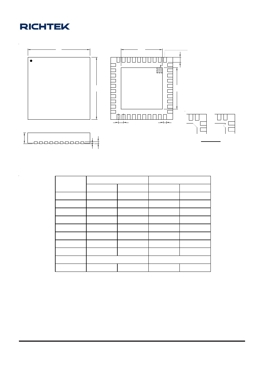
A-97
OD-100330
www.richtek.com
Dimensions In Millimeters
Dimensions In Inches
Symbol
Min Max Min Max
A
0.700 0.800 0.028 0.031
A1 0.000 0.050 0.000 0.002
A3 0.175 0.250 0.007 0.010
b
0.180 0.300 0.007 0.012
D 5.950 6.050 0.234 0.238
D2 4.000 4.750 0.157 0.187
E
5.950 6.050 0.234 0.238
E2 4.000 4.750 0.157 0.187
e 0.500
0.020
L 0.350
0.450
0.014 0.018
W-Type 40L QFN 6x6 Package
D
E
D2
E2
L
b
A
A1
A3
e
1
SEE DETAIL A
Note : The configuration of the Pin #1 identifier is optional,
but must be located within the zone indicated.
DETAIL A
Pin #1 ID and Tie Bar Mark Options
1
1
2
2
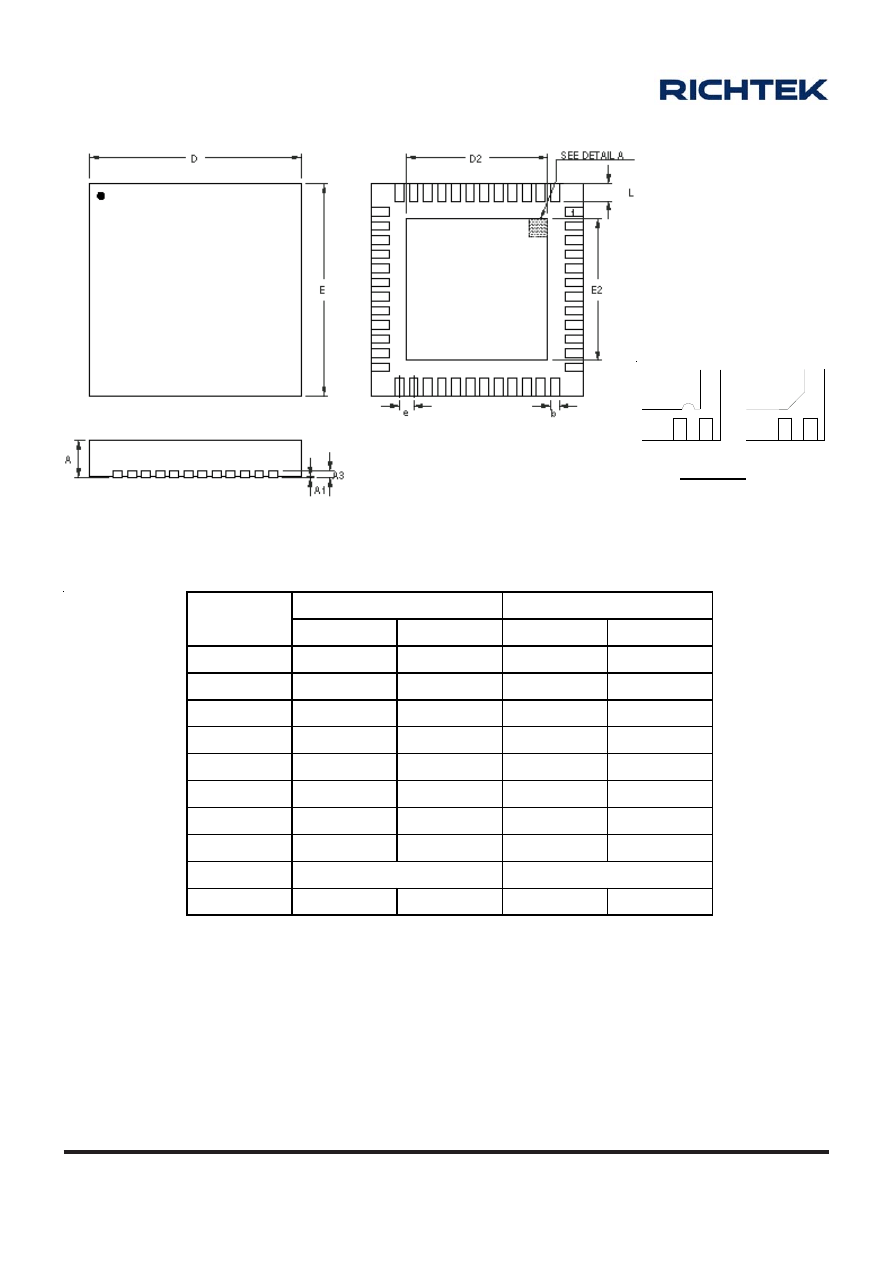
A-98
OD-100330
www.richtek.com
Dimensions In Millimeters
Dimensions In Inches
Symbol
Min Max Min Max
A
0.700 0.800 0.028 0.031
A1 0.000 0.050 0.000 0.002
A3 0.175 0.250 0.007 0.010
b
0.150 0.250 0.006 0.010
D 5.950 6.050 0.234 0.238
D2 4.250 4.350 0.167 0.171
E
5.950 6.050 0.234 0.238
E2 4.250 4.350 0.167 0.171
e 0.400
0.016
L 0.350
0.450
0.014 0.018
W-Type 48L QFN 6x6 Package
1
1
2
2
Note : The configuration of the Pin #1 identifier is optional,
but must be located within the zone indicated.
DETAIL A
Pin #1 ID and Tie Bar Mark Options
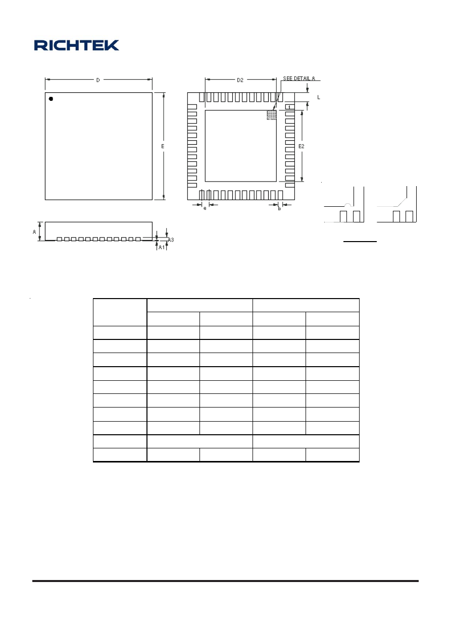
A-99
OD-100330
www.richtek.com
Symbol
D imensions In Millimeters
Dimensions In Inches
Min Max Min Max
A 0.700 0.800 0.028 0.031
A1 0.000 0.050 0.000 0.002
A3 0.175 0.250 0.007 0.010
b 0.200 0.300 0.008 0.012
D 6.950 7.050 0.274 0.278
D2 5.050 5.250 0.199 0.207
E 6.950 7.050 0.274 0.278
E2 5.050 5.250 0.199 0.207
e 0.500
0.020
L 0.350
0.450
0.014 0.018
W-Type 48L QFN 7x7 Package
1
1
2
2
Note : The configuration of the Pin #1 identifier is optional,
but must be located within the zone indicated.
DETAIL A
Pin #1 ID and Tie Bar Mark Options
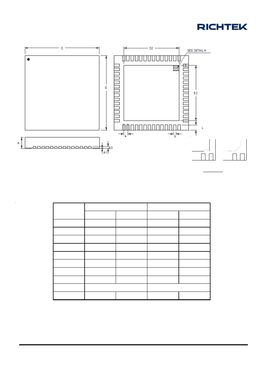
A-100
OD-100330
www.richtek.com
Symbol
Dimensions In Millimeters
Dimensions In Inches
Min Max Min Max
A 0.700 0.800 0.028 0.031
A1 0.000 0.050 0.000 0.002
A3 0.175 0.250 0.007 0.010
b
0.150 0.250 0.006 0.010
D 6.900 7.100 0.272 0.280
D2 5.150 5.250 0.203 0.207
E 6.900 7.100 0.272 0.280
E2 5.150 5.250 0.203 0.207
e 0.400
0.020
L 0.350
0.450
0.014 0.018
W-Type 56L QFN 7x7 Package
1
1
2
2
Note : The configuration of the Pin #1 identifier is optional,
but must be located within the zone indicated.
DETAIL A
Pin #1 ID and Tie Bar Mark Options
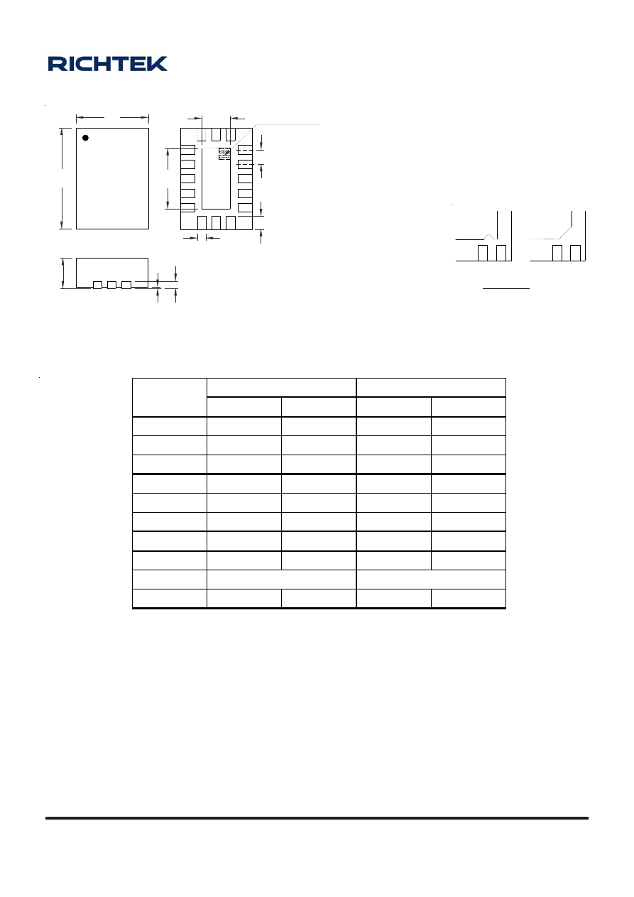
A-101
OD-100330
www.richtek.com
Dimensions In Millimeters
Dimensions In Inches
Symbol
Min Max Min Max
A 0.700
0.800
0.028
0.031
A1 0.000
0.050
0.000
0.002
A3 0.175
0.250
0.007
0.010
b 0.150
0.250
0.006
0.010
D 1.900
2.100
0.075
0.083
D2 0.700
0.800
0.028
0.031
E 2.900
3.100
0.114
0.122
E2 1.700
1.800
0.067
0.071
e 0.400
0.016
L 0.325
0.425
0.013 0.017
W-Type 16L QFN 2x3 Package
1
1
2
2
Note : The configuration of the Pin #1 identifier is optional,
but must be located within the zone indicated.
DETAIL A
Pin #1 ID and Tie Bar Mark Options
D
E
L
D2
E2
A3
A
A1
b
SEE DETAIL A
e
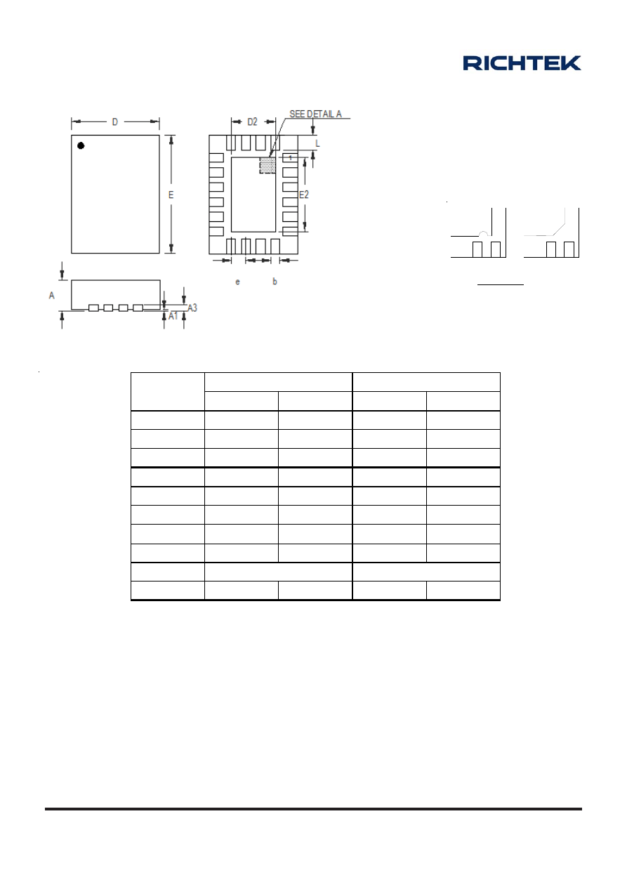
A-102
OD-100330
www.richtek.com
Symbol
Dimensions In Millimeters
Dimensions In Inches
Min Max Min Max
A 0.700 0.800 0.028 0.031
A1 0.000 0.050 0.000 0.002
A3 0.175 0.250 0.007 0.010
b
0.180 0.300 0.007 0.012
D 2.900
3.100
0.114
0.122
D2 1.600 1.700 0.063 0.067
E 3.900 4.100 0.154 0.161
E2 2.600 2.700 0.102 0.106
e 0.500
0.020
L 0.350
0.450
0.014 0.018
W-Type 20L QFN 3x4 Package
1
1
2
2
Note : The configuration of the Pin #1 identifier is optional,
but must be located within the zone indicated.
DETAIL A
Pin #1 ID and Tie Bar Mark Options
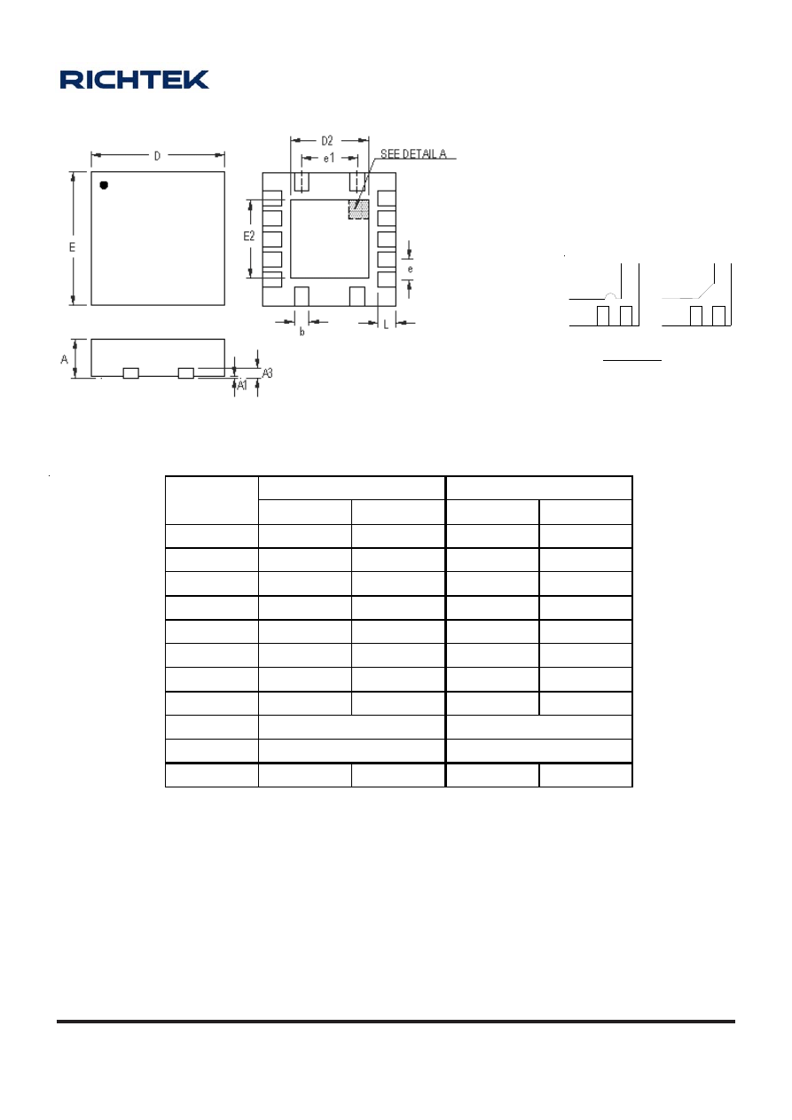
A-103
OD-100330
www.richtek.com
Symbol
Dimensions In Millimeters
Dimensions In Inches
Min Max Min Max
A 0.700 0.800 0.028 0.031
A1 0.000 0.050 0.000 0.002
A3 0.175 0.250 0.007 0.010
b
0.180 0.300 0.007 0.012
D 3.400 3.600 0.134 0.142
D2 1.950 2.150 0.077 0.085
E 3.400 3.600 0.134 0.142
E2 1.950 2.150 0.077 0.085
e 0.500
0.020
e1 1.500
0.060
L 0.300
0.500
0.012 0.020
W-Type 14L QFN 3.5x3.5 Package
1
1
2
2
Note : The configuration of the Pin #1 identifier is optional,
but must be located within the zone indicated.
DETAIL A
Pin #1 ID and Tie Bar Mark Options
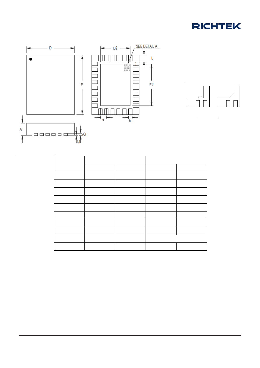
A-104
OD-100330
www.richtek.com
Symbol
Dimensions In Millimeters
Dimensions In Inches
Min Max Min Max
A 0.700 0.800 0.028 0.031
A1 0.000 0.050 0.000 0.002
A3 0.175 0.250 0.007 0.010
b
0.180 0.300 0.007 0.012
D 3.900 4.100 0.154 0.161
D2 2.600 2.700 0.102 0.106
E 4.900 5.100 0.193 0.201
E2 3.600 3.700 0.142 0.146
e 0.500
0.020
L 0.350
0.450
0.014 0.018
W-Type 28L QFN 4x5 Package
1
1
2
2
Note : The configuration of the Pin #1 identifier is optional,
but must be located within the zone indicated.
DETAIL A
Pin #1 ID and Tie Bar Mark Options
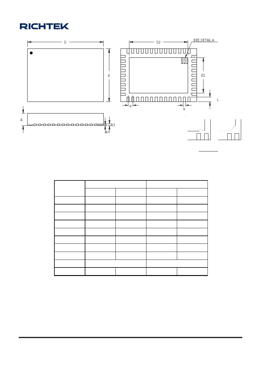
A-105
OD-100330
www.richtek.com
Symbol
D imensions In Millimeters
Dim ensions In Inches
Min Max Min Max
A 0.700 0.800 0.028 0.031
A1 0.000 0.050 0.000 0.002
A3 0.175 0.250 0.007 0.010
b 0.150 0.250 0.006 0.010
D 6.400 6.600 0.252 0.260
D2 5.050 5.150 0.199 0.203
E 4.400 4.600 0.173 0.181
E2 3.050 3.150 0.120 0.124
e 0.400
0.020
L 0.350
0.450
0.014 0.018
W-Type 46L QFN 6.5x4.5 Package
1
1
2
2
Note : The configuration of the Pin #1 identifier is optional,
but must be located within the zone indicated.
DETAIL A
Pin #1 ID and Tie Bar Mark Options
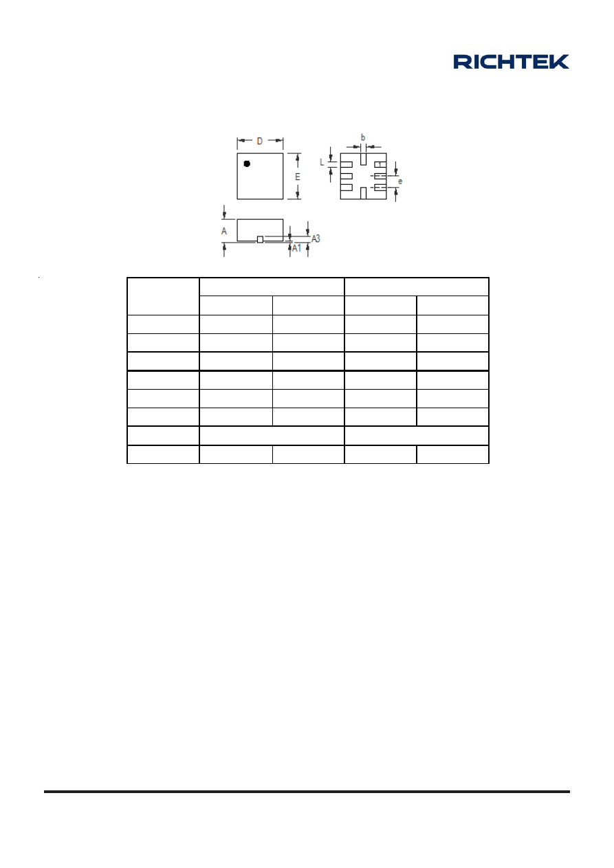
A-106
OD-100330
www.richtek.com
Symbol
Dimensions In Millimeters
Dimensions In Inches
Min Max Min Max
A 0.700 0.800 0.028 0.031
A1 0.000 0.050 0.000 0.002
A3 0.175 0.250 0.007 0.010
b
0.150 0.250 0.006 0.010
D 1.550 1.650 0.061 0.065
E 1.550 1.650 0.061 0.065
e 0.400
0.016
L 0.350
0.450
0.014 0.018
W-Type 8L QFN 1.6x1.6 (COL) Package
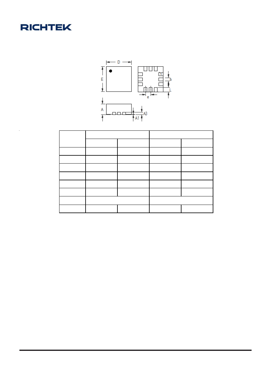
A-107
OD-100330
www.richtek.com
Symbol
Dimensions In Millimeters
Dimensions In Inches
Min Max Min Max
A 0.700 0.800 0.028 0.031
A1 0.000 0.050 0.000 0.002
A3 0.175 0.250 0.007 0.010
b 0.150 0.250 0.006 0.010
D 1.900 2.100 0.075 0.083
E 1.900 2.100 0.075 0.083
e 0.400
0.016
L 0.350 0.450 0.014 0.018
W-Type 12L QFN 2x2 (COL) Package
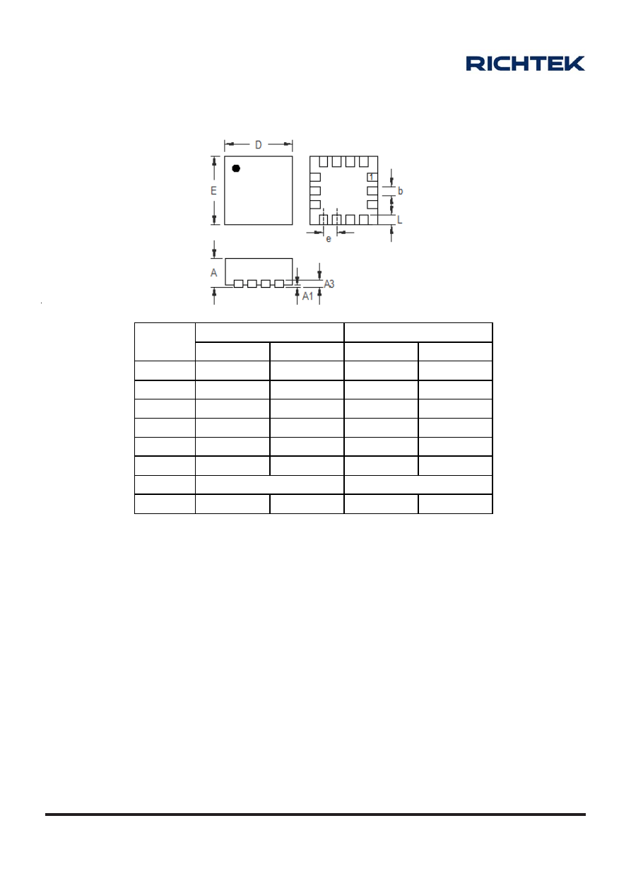
A-108
OD-100330
www.richtek.com
Dimensions In Millimeters
Dimensions In Inches
Symbol
Min Max Min Max
A 0.700 0.800 0.028 0.031
A1 0.000 0.050 0.000 0.002
A3 0.175 0.250 0.007 0.010
b 0.150 0.250 0.006 0.010
D 1.900 2.100 0.075 0.083
E 1.900 2.100 0.075 0.083
e 0.400
0.016
L 0.300 0.400 0.012 0.016
W-Type 14L QFN 2x2 (COL) Package
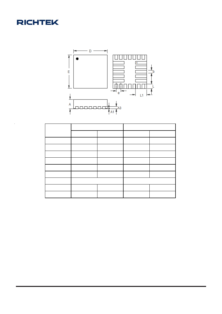
A-109
OD-100330
www.richtek.com
Dimensions In Millimeters
Dimensions In Inches
Symbol
Min Max Min Max
A 0.700
0.800
0.028
0.031
A1 0.000
0.050
0.000
0.002
A3 0.175
0.250
0.007
0.010
b 0.150
0.250
0.006
0.010
D 2.900
3.100
0.114
0.122
E 2.900
3.100
0.114
0.122
e 0.400
0.016
L 0.350
0.450
0.014 0.018
L1 0.950
1.050
0.037 0.041
W-Type 24L QFN 3x3 (COL) Package
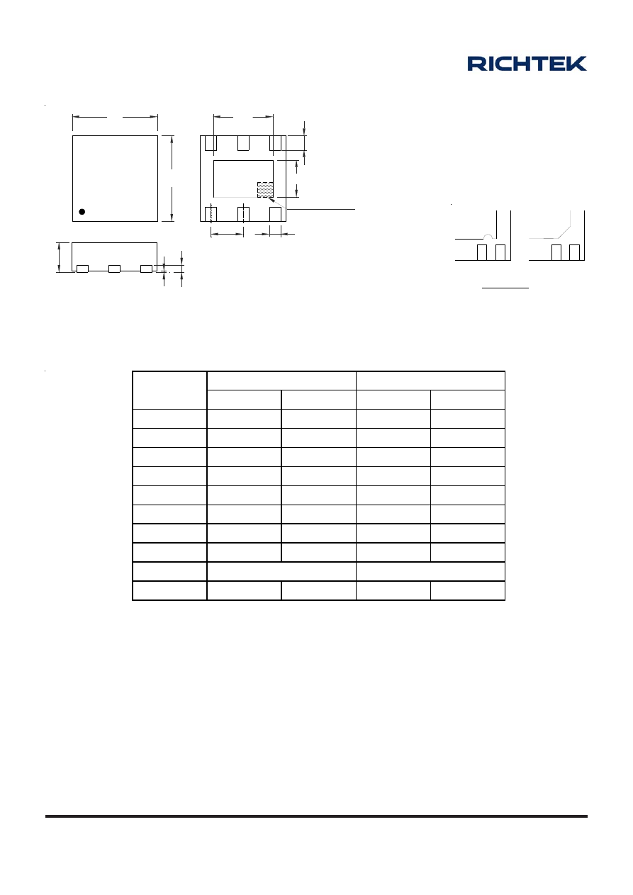
A-110
OD-100330
www.richtek.com
Dimensions In Millimeters
Dimensions In Inches
Symbol
Min Max Min Max
A
0.700 0.800 0.028 0.031
A1 0.000 0.050 0.000 0.002
A3 0.175
0.250
0.007 0.010
b
0.200 0.350 0.008 0.014
D 1.950 2.050 0.077 0.081
D2 1.000 1.450 0.039 0.057
E
1.950 2.050 0.077 0.081
E2 0.500 0.850 0.020 0.033
e 0.650
0.026
L 0.300
0.400
0.012 0.016
W-Type 6L DFN 2x2 Package
D
1
E
A3
A
A1
e
b
L
D2
E2
SEE DETAIL A
1
1
2
2
Note : The configuration of the Pin #1 identifier is optional,
but must be located within the zone indicated.
DETAIL A
Pin #1 ID and Tie Bar Mark Options
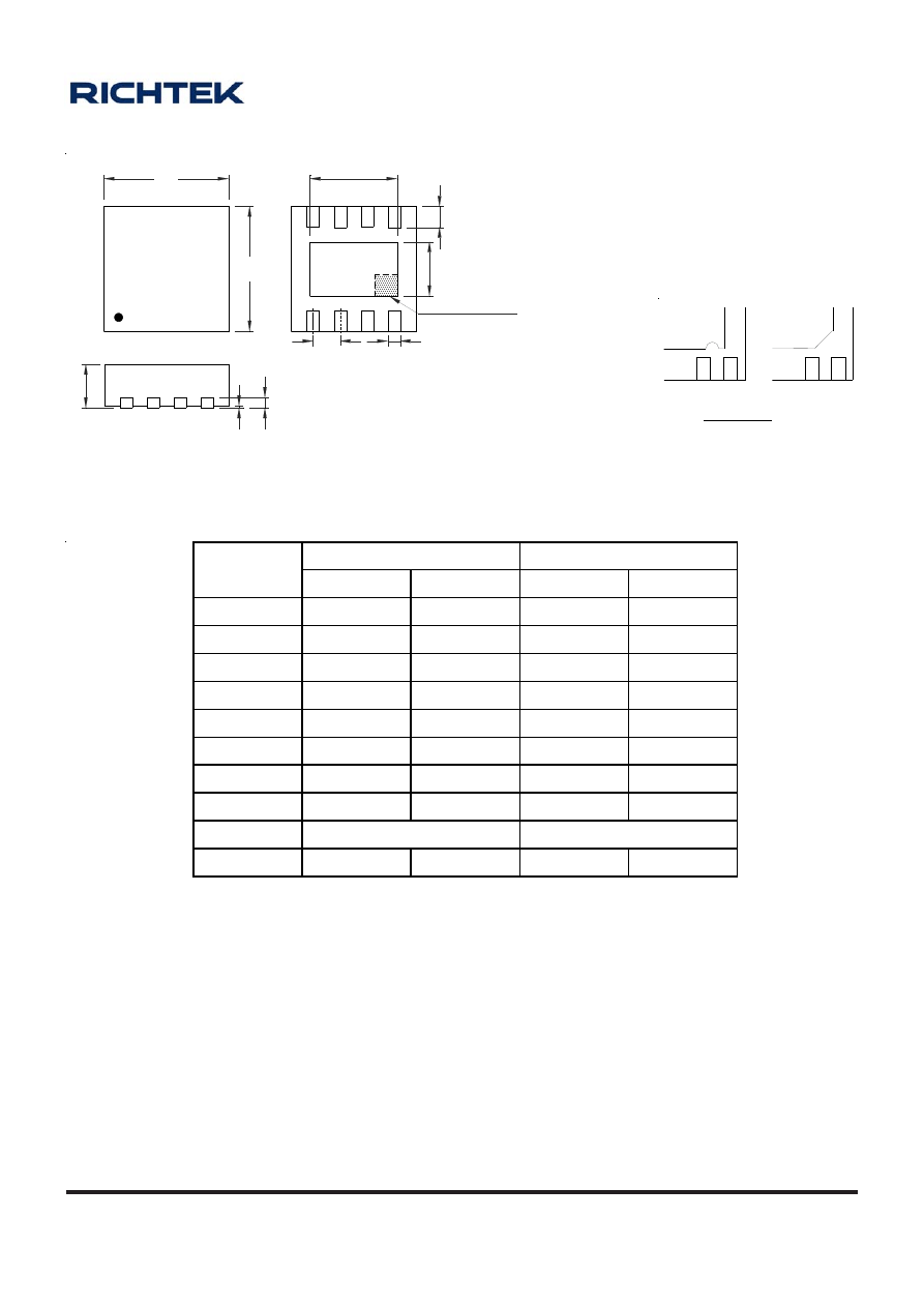
A-111
OD-100330
www.richtek.com
W-Type 8L DFN 2x2 Package
Dimensions In Millimeters
Dimensions In Inches
Symbol
Min Max Min Max
A
0.700 0.800 0.028 0.031
A1 0.000 0.050 0.000 0.002
A3 0.175 0.250 0.007 0.010
b
0.200 0.300 0.008 0.012
D 1.950 2.050 0.077 0.081
D2 1.000 1.250 0.039 0.049
E
1.950 2.050 0.077 0.081
E2 0.400 0.650 0.016 0.026
e 0.500
0.020
L 0.300
0.400
0.012 0.016
1
1
2
2
Note : The configuration of the Pin #1 identifier is optional,
but must be located within the zone indicated.
DETAIL A
Pin #1 ID and Tie Bar Mark Options
D
1
E
A3
A
A1
D2
E2
L
b
e
SEE DETAIL A
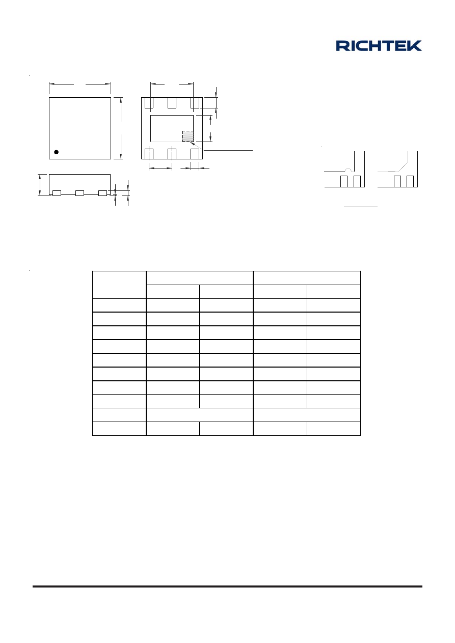
A-112
OD-100330
www.richtek.com
Dimensions In Millimeters
Dimensions In Inches
Symbol
Min Max Min Max
A
0.700 0.800 0.028 0.031
A1 0.000 0.050 0.000 0.002
A3 0.175 0.250 0.007 0.010
b
0.350 0.450 0.014 0.018
D 2.950
3.050
0.116
0.120
D2 2.200 2.400 0.087 0.094
E 2.950
3.050
0.116
0.120
E2 1.400 1.600 0.055 0.063
e 0.950
0.037
L 0.425
0.525
0.017 0.021
W-Type 6L DFN 3x3 Package
D
1
E
A3
A
A1
e
b
L
D2
E2
SEE DETAIL A
1
1
2
2
Note : The configuration of the Pin #1 identifier is optional,
but must be located within the zone indicated.
DETAIL A
Pin #1 ID and Tie Bar Mark Options
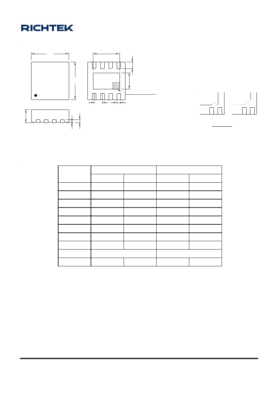
A-113
OD-100330
www.richtek.com
Dimensions In Millimeters
Dimensions In Inches
Symbol
Min Max Min Max
A
0.700 0.800 0.028 0.031
A1 0.000 0.050 0.000 0.002
A3 0.175 0.250 0.007 0.010
b
0.200 0.300 0.008 0.012
D 2.950 3.050 0.116 0.120
D2 2.100 2.350 0.083 0.093
E 2.950 3.050 0.116 0.120
E2 1.350 1.600 0.053 0.063
e 0.650
0.026
L 0.425
0.525
0.017 0.021
W-Type 8L DFN 3x3 Package
1
1
2
2
Note : The configuration of the Pin #1 identifier is optional,
but must be located within the zone indicated.
DETAIL A
Pin #1 ID and Tie Bar Mark Options
D
1
E
A3
A
A1
D2
E2
L
b
e
SEE DETAIL A
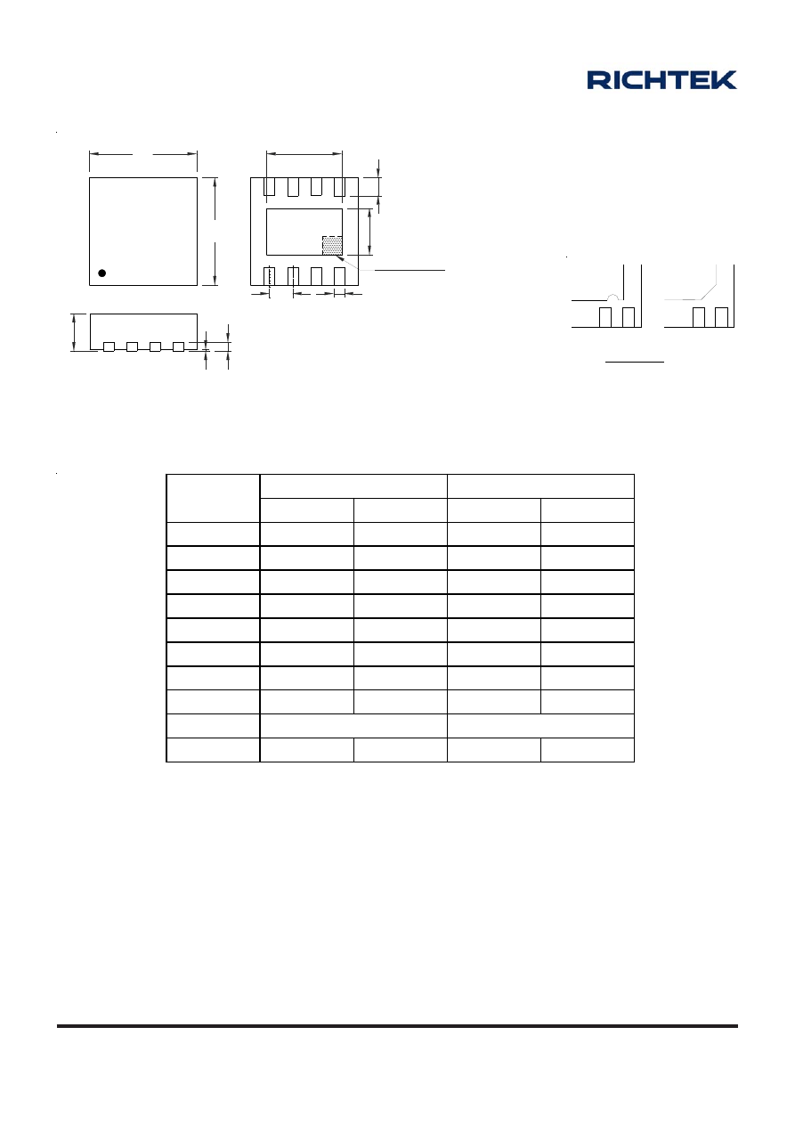
A-114
OD-100330
www.richtek.com
Dimensions In Millimeters
Dimensions In Inches
Symbol
Min Max Min Max
A
0.700 0.800 0.028 0.031
A1 0.000 0.050 0.000 0.002
A3 0.175 0.250 0.007 0.010
b
0.180 0.300 0.007 0.012
D 2.950 3.050 0.116 0.120
D2 2.200 2.700 0.087 0.106
E 2.950 3.050 0.116 0.120
E2 1.450 1.750 0.057 0.069
e 0.500
0.020
L 0.350
0.450
0.014 0.018
W-Type 8L DFN 3x3 Package, 0.5mm Lead Pitch
1
1
2
2
Note : The configuration of the Pin #1 identifier is optional,
but must be located within the zone indicated.
DETAIL A
Pin #1 ID and Tie Bar Mark Options
D
1
E
A3
A
A1
D2
E2
L
b
e
SEE DETAIL A
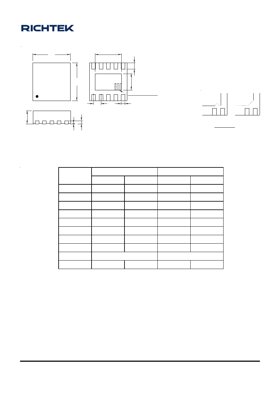
A-115
OD-100330
www.richtek.com
Dimensions In Millimeters
Dimensions In Inches
Symbol
Min Max Min Max
A
0.700 0.800 0.028 0.031
A1 0.000 0.050 0.000 0.002
A3 0.175 0.250 0.007 0.010
b
0.180 0.300 0.007 0.012
D 2.950
3.050
0.116
0.120
D2 2.300 2.650 0.091 0.104
E 2.950
3.050
0.116
0.120
E2 1.500 1.750 0.059 0.069
e 0.500
0.020
L 0.350
0.450
0.014 0.018
W-Type 10L DFN 3x3 Package
1
1
2
2
Note : The configuration of the Pin #1 identifier is optional,
but must be located within the zone indicated.
DETAIL A
Pin #1 ID and Tie Bar Mark Options
D
1
E
A3
A
A1
D2
E2
L
b
e
SEE DETAIL A
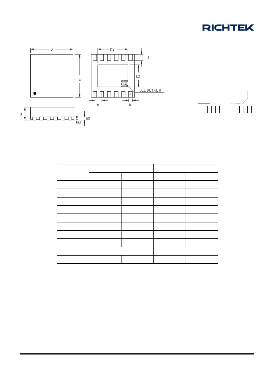
A-116
OD-100330
www.richtek.com
Dimensions In Millimeters
Dimensions In Inches
Symbol
Min Max Min Max
A 0.700
0.800
0.028
0.031
A1 0.000
0.050
0.000
0.002
A3 0.175
0.250
0.007
0.010
b 0.150
0.250
0.006
0.010
D 2.950
3.050
0.116
0.120
D2 2.300
2.650
0.091
0.104
E 2.950
3.050
0.116
0.120
E2 1.400
1.750
0.055
0.069
e 0.450
0.018
L 0.350
0.450
0.014 0.018
W-Type 12L DFN 3x3 Package
1
1
2
2
Note : The configuration of the Pin #1 identifier is optional,
but must be located within the zone indicated.
DETAIL A
Pin #1 ID and Tie Bar Mark Options
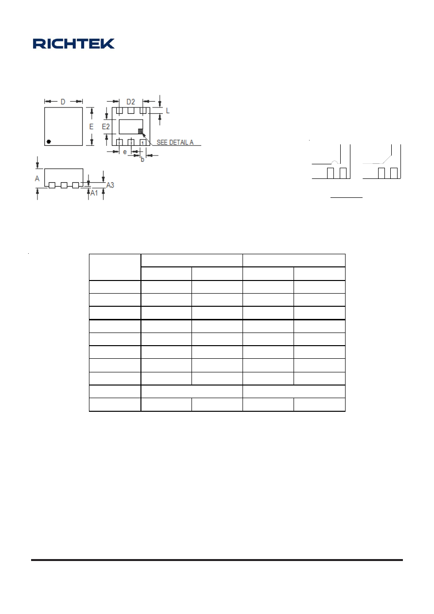
A-117
OD-100330
www.richtek.com
Symbol
D imensions In Millimeters
Dimensions In Inches
Min Max Min Max
A 0.700 0.800 0.028 0.031
A1 0.000 0.050 0.000 0.002
A3 0.175
0.250
0.007 0.010
b 0.200 0.300 0.008 0.012
D 1.550 1.650 0.061 0.065
D2 0.950 1.050 0.037 0.041
E 1.550 1.650 0.061 0.065
E2 0.550 0.650 0.022 0.026
e 0.500
0.020
L 0.190
0.290
0.007 0.011
W-Type 6L DFN 1.6x1.6 Package
1
1
2
2
Note : The configuration of the Pin #1 identifier is optional,
but must be located within the zone indicated.
DETAIL A
Pin #1 ID and Tie Bar Mark Options
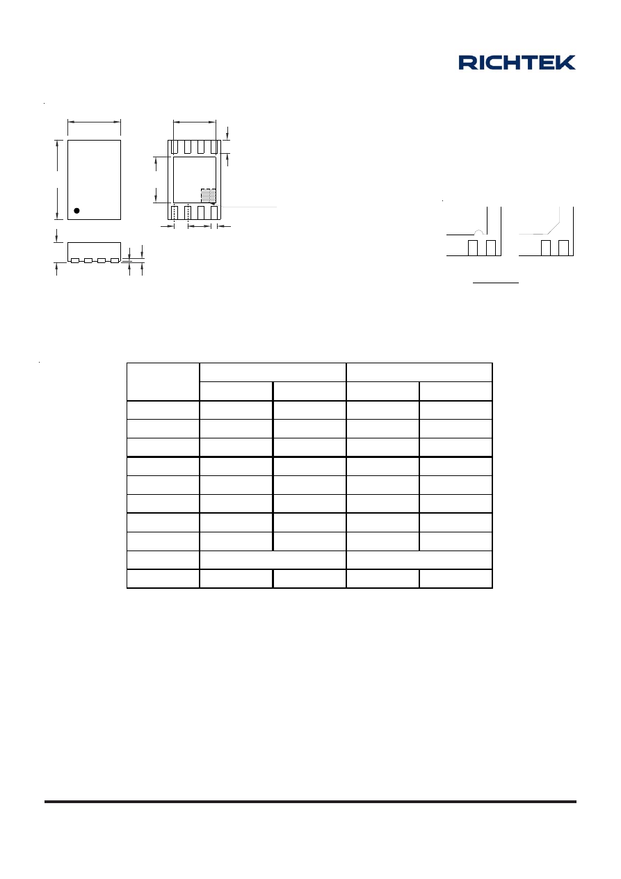
A-118
OD-100330
www.richtek.com
Dimensions In Millimeters
Dim ensions In Inches
Symbol
Min Max Min Max
A 0.700 0.800 0.028 0.031
A1 0.000 0.050 0.000 0.002
A3 0.175
0.250
0.007 0.010
b
0.200 0.300 0.008 0.012
D 1.900 2.100 0.075 0.083
D2 1.550 1.650 0.061 0.065
E 2.900
3.100
0.114
0.122
E2 1.650 1.750 0.065 0.069
e 0.500
0.020
L 0.350
0.450
0.014 0.018
W-Type 8L DFN 2x3 Package
1
1
2
2
Note : The configuration of the Pin #1 identifier is optional,
but must be located within the zone indicated.
DETAIL A
Pin #1 ID and Tie Bar Mark Options
D
1
E
A3
A
A1
D2
E2
L
b
e
SEE DETAIL A
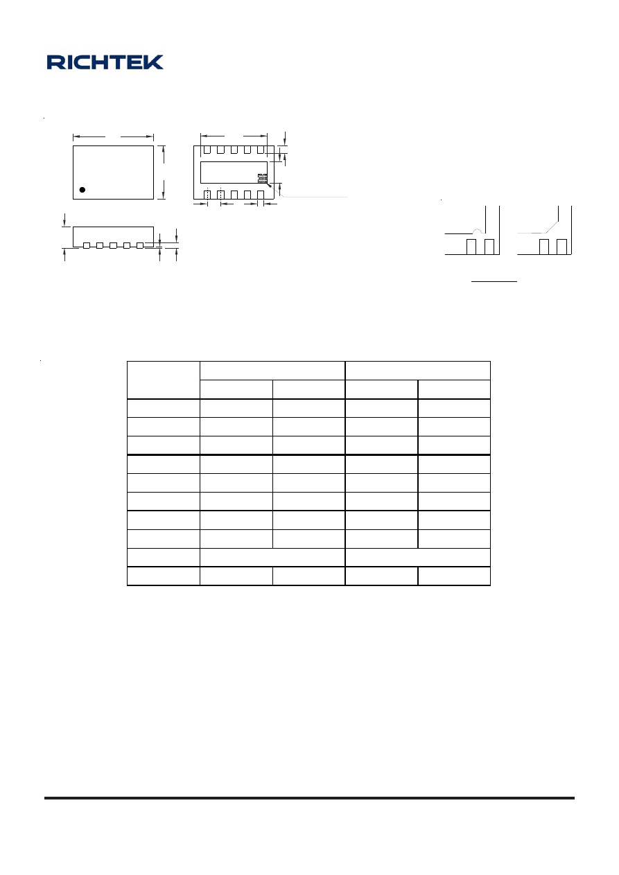
A-119
OD-100330
www.richtek.com
1
1
2
2
Note : The configuration of the Pin #1 identifier is optional,
but must be located within the zone indicated.
DETAIL A
Pin #1 ID and Tie Bar Mark Options
D
1
E
A3
A
A1
D2
E2
L
b
e
SEE DETAIL A
Symbol
Dimensions In Millimeters
Dimensions In Inches
Min Max Min Max
A 0.700 0.800 0.028 0.031
A1 0.000 0.050 0.000 0.002
A3 0.175
0.250
0.007 0.010
b
0.180 0.300 0.007 0.012
D 2.900 3.100 0.114 0.122
D 2 2.450 2.550 0.096 0.100
E 1.900 2.100 0.075 0.083
E2 0.750 0.850 0.030 0.033
e 0.500
0.020
L 0.250
0.350
0.010 0.014
W-Type 10L DFN 3x2 Package
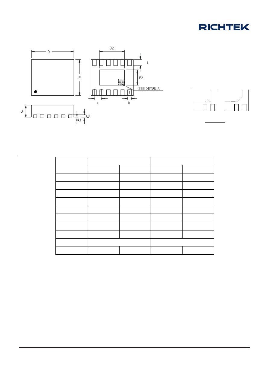
A-120
OD-100330
www.richtek.com
Symbol
Dimensions In Millimeters
Dimensions In Inches
Min Max Min Max
A 0.700 0.800 0.028 0.031
A1 0.000 0.050 0.000 0.002
A3 0.175 0.250 0.007 0.010
b
0.180 0.300 0.007 0.012
D 3.950 4.050 0.156 0.159
D2 3.250 3.350 0.128 0.132
E 2.950 3.050 0.116 0.120
E2 1.650 1.750 0.065 0.069
e 0.500
0.020
L 0.350
0.450
0.014 0.018
W-Type 12L DFN 4x3 Package
1
1
2
2
Note : The configuration of the Pin #1 identifier is optional,
but must be located within the zone indicated.
DETAIL A
Pin #1 ID and Tie Bar Mark Options
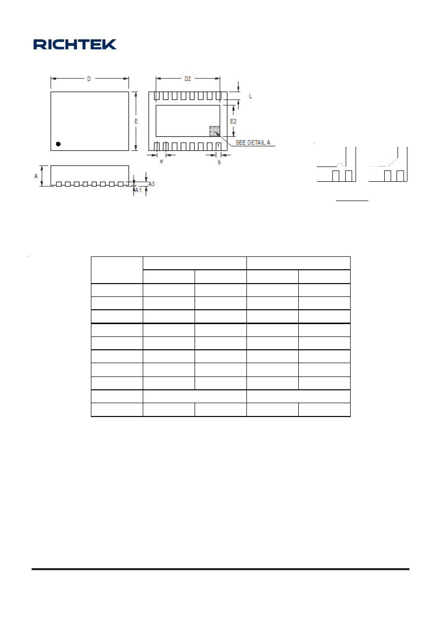
A-121
OD-100330
www.richtek.com
Symbol
Dimensions In Millimeters
D imensions In Inches
Min Max Min Max
A 0.700 0.800 0.028 0.031
A1 0.000 0.050 0.000 0.002
A3 0.175 0.250 0.007 0.010
b
0.150 0.250 0.006 0.010
D 3.900 4.100 0.154 0.161
D2 3.250 3.350 0.128 0.132
E 2.900 3.100 0.114 0.122
E2 1.550 1.650 0.061 0.065
e 0.450
0.020
L 0.300
0.400
0.012 0.016
W-Type 16L DFN 4x3 Package
1
1
2
2
Note : The configuration of the Pin #1 identifier is optional,
but must be located within the zone indicated.
DETAIL A
Pin #1 ID and Tie Bar Mark Options
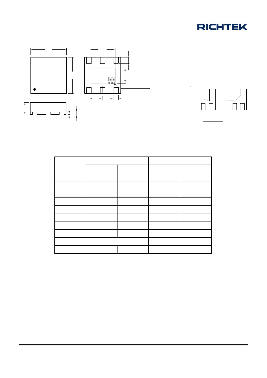
A-122
OD-100330
www.richtek.com
Symbol
Dimensions In Millimeters
Dimensions In Inches
Min Max Min Max
A 0.700 0.800 0.028 0.031
A1 0.000 0.050 0.000 0.002
A3 0.175
0.250
0.007 0.010
b
0.200 0.350 0.008 0.014
D 1.900 2.100 0.075 0.083
D2 1.550 1.650 0.061 0.065
E 1.900 2.100 0.075 0.083
E2 0.950 1.050 0.037 0.041
e 0.650
0.026
L 0.200
0.300
0.008 0.012
W-Type 6SL DFN 2x2 Package
D
1
E
A3
A
A1
e
b
L
D2
E2
SEE DETAIL A
1
1
2
2
Note : The configuration of the Pin #1 identifier is optional,
but must be located within the zone indicated.
DETAIL A
Pin #1 ID and Tie Bar Mark Options
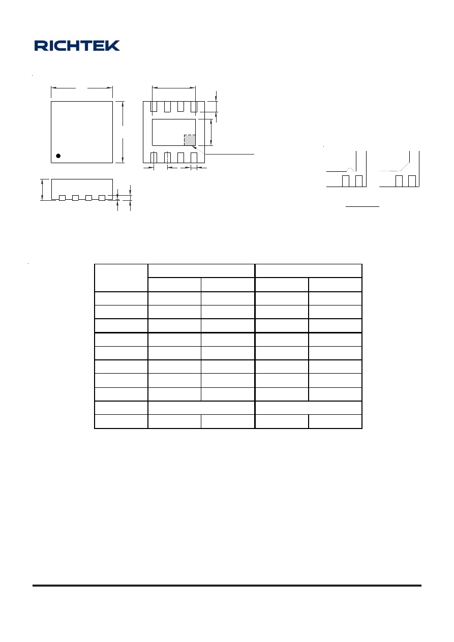
A-123
OD-100330
www.richtek.com
X-Type 8L DFN 2x2 Package
Symbol
Dimensions In Millimeters
Dimensions In Inches
Min Max Min Max
A 0.400 0.500 0.016 0.020
A1 0.000 0.050 0.000 0.002
A3 0.100 0.150 0.004 0.006
b
0.200 0.300 0.008 0.012
D 1.950 2.050 0.077 0.081
D2 1.000 1.250 0.039 0.049
E 1.950 2.050 0.077 0.081
E2 0.400 0.650 0.016 0.026
e 0.500
0.020
L 0.300
0.400
0.012 0.016
1
1
2
2
Note : The configuration of the Pin #1 identifier is optional,
but must be located within the zone indicated.
DETAIL A
Pin #1 ID and Tie Bar Mark Options
D
1
E
A3
A
A1
D2
E2
L
b
e
SEE DETAIL A
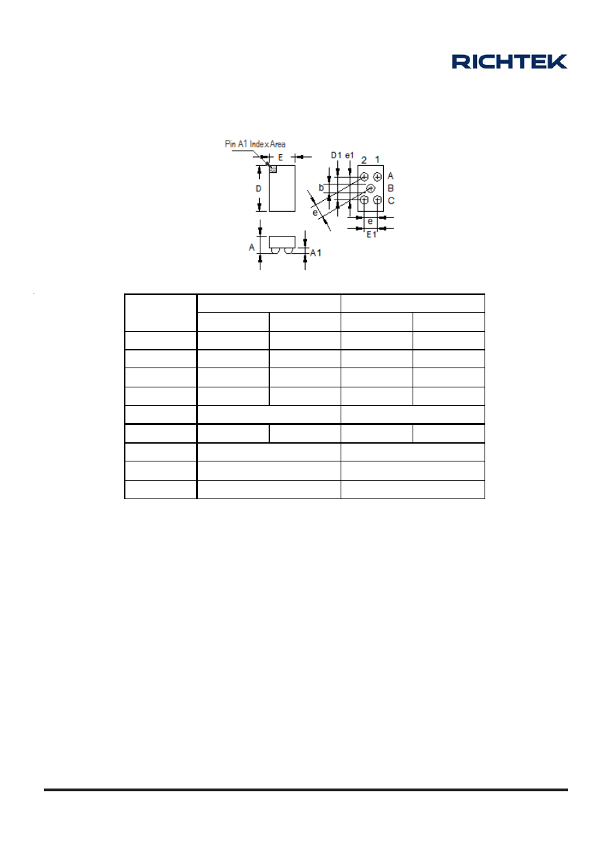
A-124
OD-100330
www.richtek.com
5B WL-CSP 0.70x1.35 Package
Symbol
Dimensions In Millimeters
Dimensions In Inches
Min Max Min Max
A 0.500 0.600 0.020 0.024
A1 0.130 0.180 0.005 0.007
b 0.180 0.250 0.007 0.010
D 1.300 1.400 0.051 0.055
D1 0.693
0.027
E 0.680 0.780 0.027 0.031
E1 0.400
0.016
e 0.400
0.016
e1 0.693
0.027
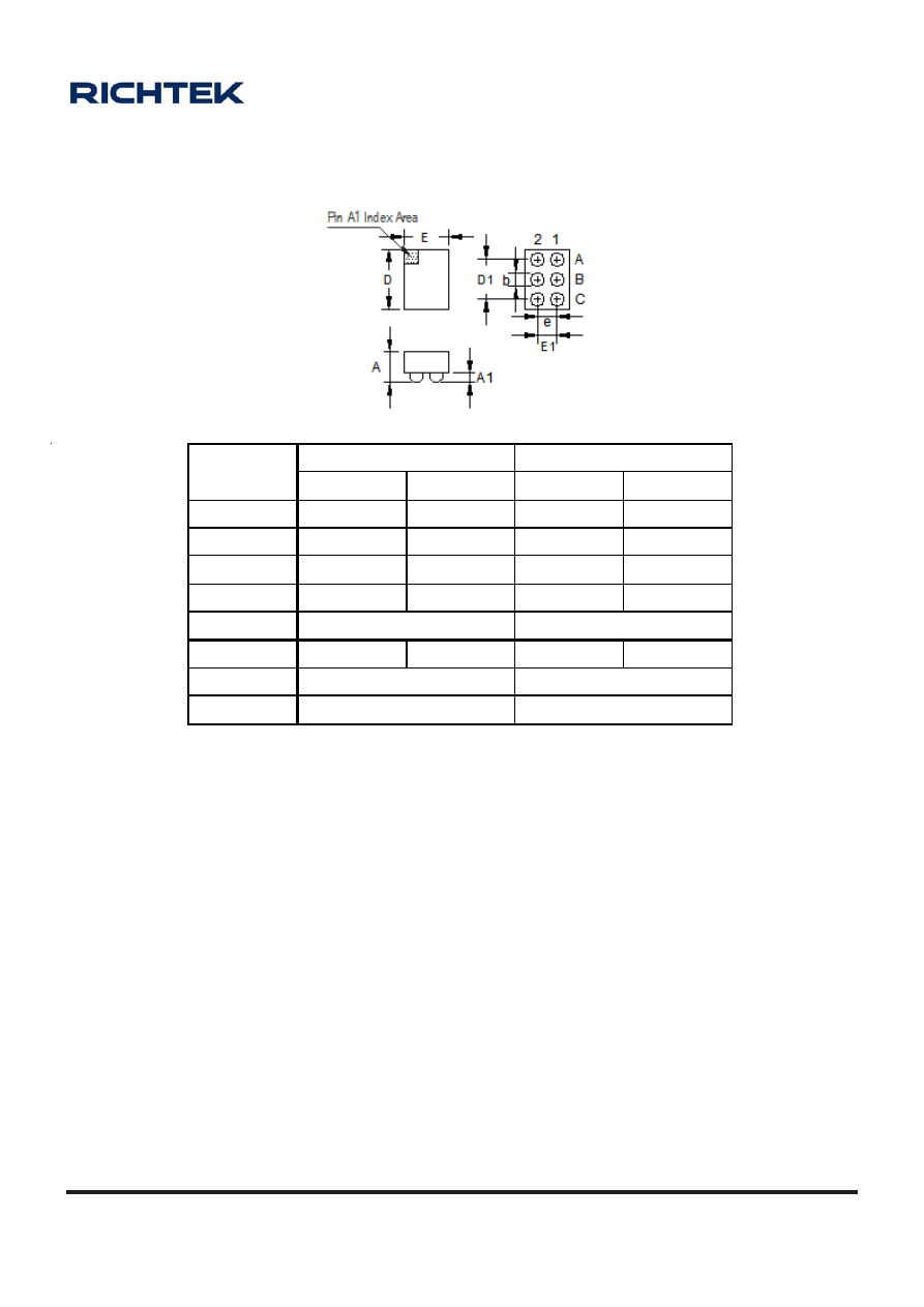
A-125
OD-100330
www.richtek.com
6B WL-CSP 0.9x1.3 Package
Symbol
Dimensions In Millimeters
Dimensions In Inches
Min Max Min Max
A 0.500 0.600 0.020 0.024
A1 0.130 0.180 0.005 0.007
b 0.180 0.250 0.007 0.010
D 1.250 1.350 0.049 0.053
D1 0.800
0.031
E 0.850 0.950 0.033 0.037
E1 0.400
0.016
e 0.400
0.016
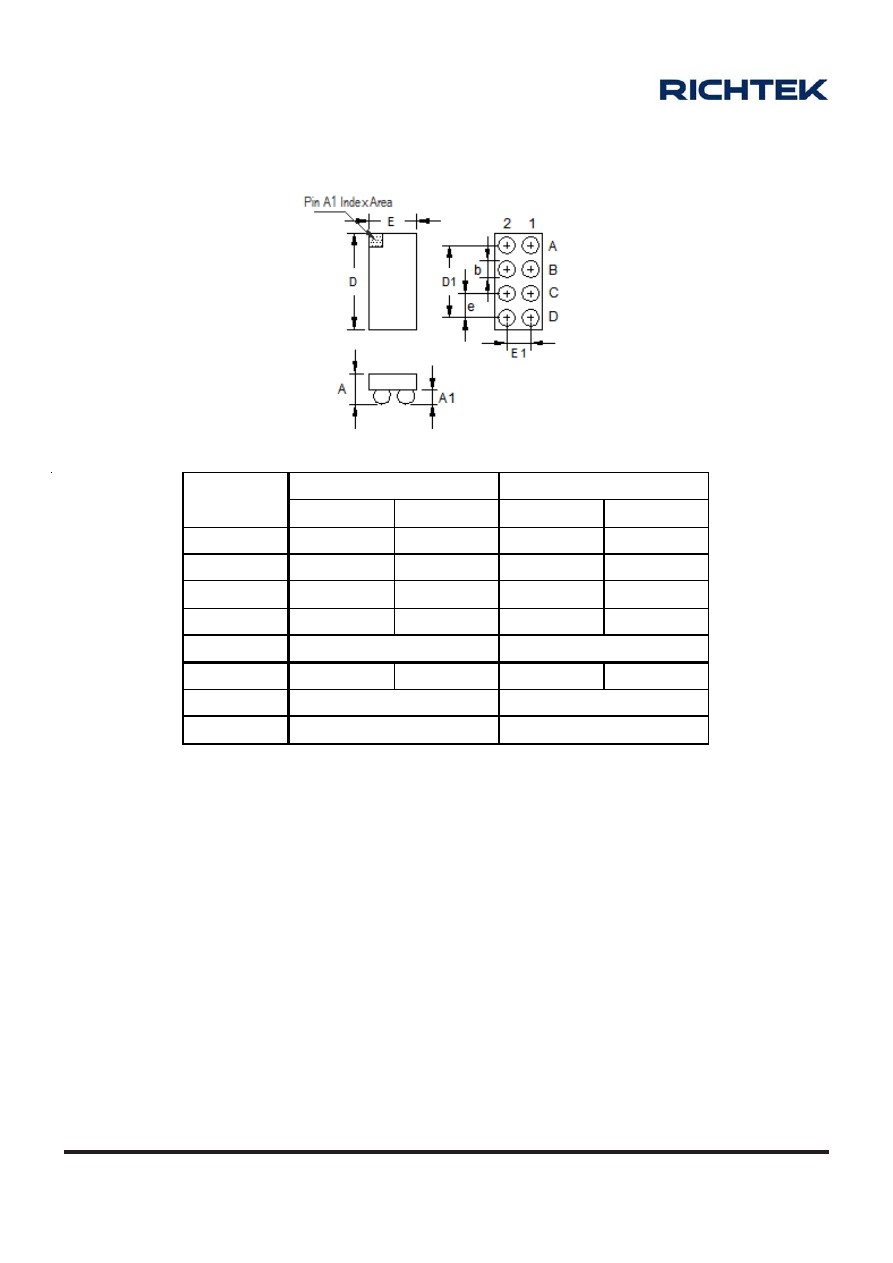
A-126
OD-100330
www.richtek.com
8B WL-CSP 1x2 Package
Symbol
Dimensions In Millimeters
Dimensions In Inches
Min Max Min Max
A 0.525 0.625 0.021 0.025
A1 0.200 0.260 0.008 0.010
b 0.290
0.350
0.011
0.014
D 1.950 2.050 0.077 0.081
D1 1.500
0.059
E 0.950 1.050 0.037 0.041
E1 0.500
0.020
e 0.500
0.020
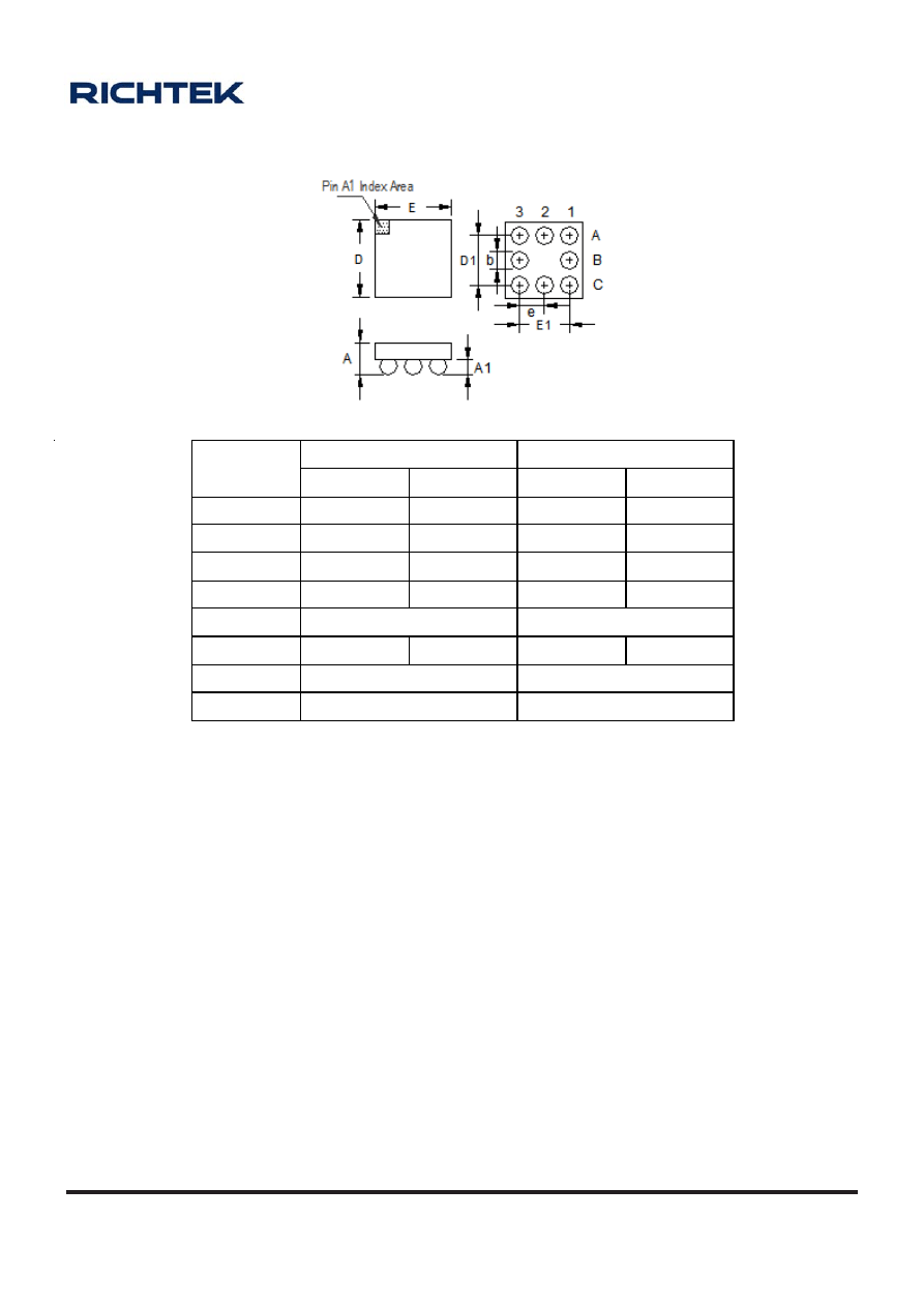
A-127
OD-100330
www.richtek.com
8B WL-CSP 1.5x1.5 Package
Symbol
Dimensions In Millimeters
Dimensions In Inches
Min Max Min Max
A
0.525 0.625 0.021 0.025
A1 0.200 0.260 0.008 0.010
b 0.290 0.350 0.011 0.014
D 1.450 1.550 0.057 0.061
D1 1.000
0.039
E
1.450 1.550 0.057 0.061
E1 1.000
0.039
e 0.500
0.020
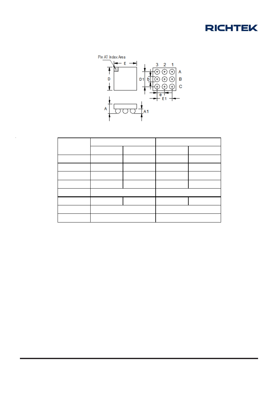
A-128
OD-100330
www.richtek.com
9B WL-CSP 1.5x1.5 Package
Symbol
Dimensions In Millimeters
Dimensions In Inches
Min Max Min Max
A 0.500 0.700 0.020 0.028
A1 0.150 0.350 0.006 0.014
b
0.250 0.350 0.010 0.014
D 1.450 1.550 0.057 0.061
D1 1.000
0.039
E 1.450 1.550 0.057 0.061
E1 1.000
0.039
e 0.500
0.020
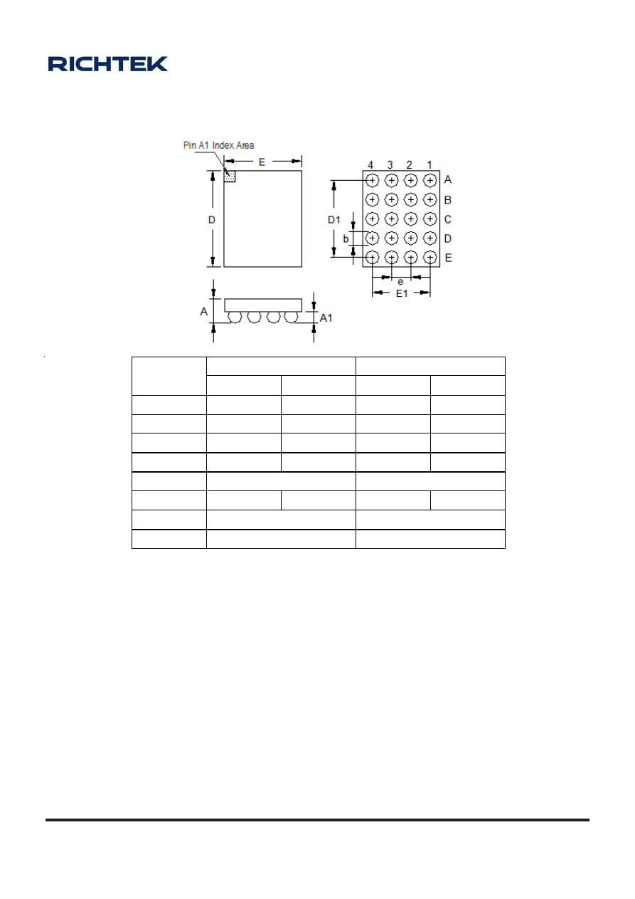
A-129
OD-100330
www.richtek.com
Symbol
Dimensions In Millimeters
Dimensions In Inches
Min Max Min Max
A 0.525 0.625 0.021 0.025
A1 0.200 0.260 0.008 0.010
b
0.290 0.350 0.011 0.014
D 2.500 2.600 0.098 0.102
D1 2.000
0.079
E 2.000 2.100 0.079 0.083
E1 1.500
0.059
e 0.500
0.020
WL-CSP-20B 2.05x2.55
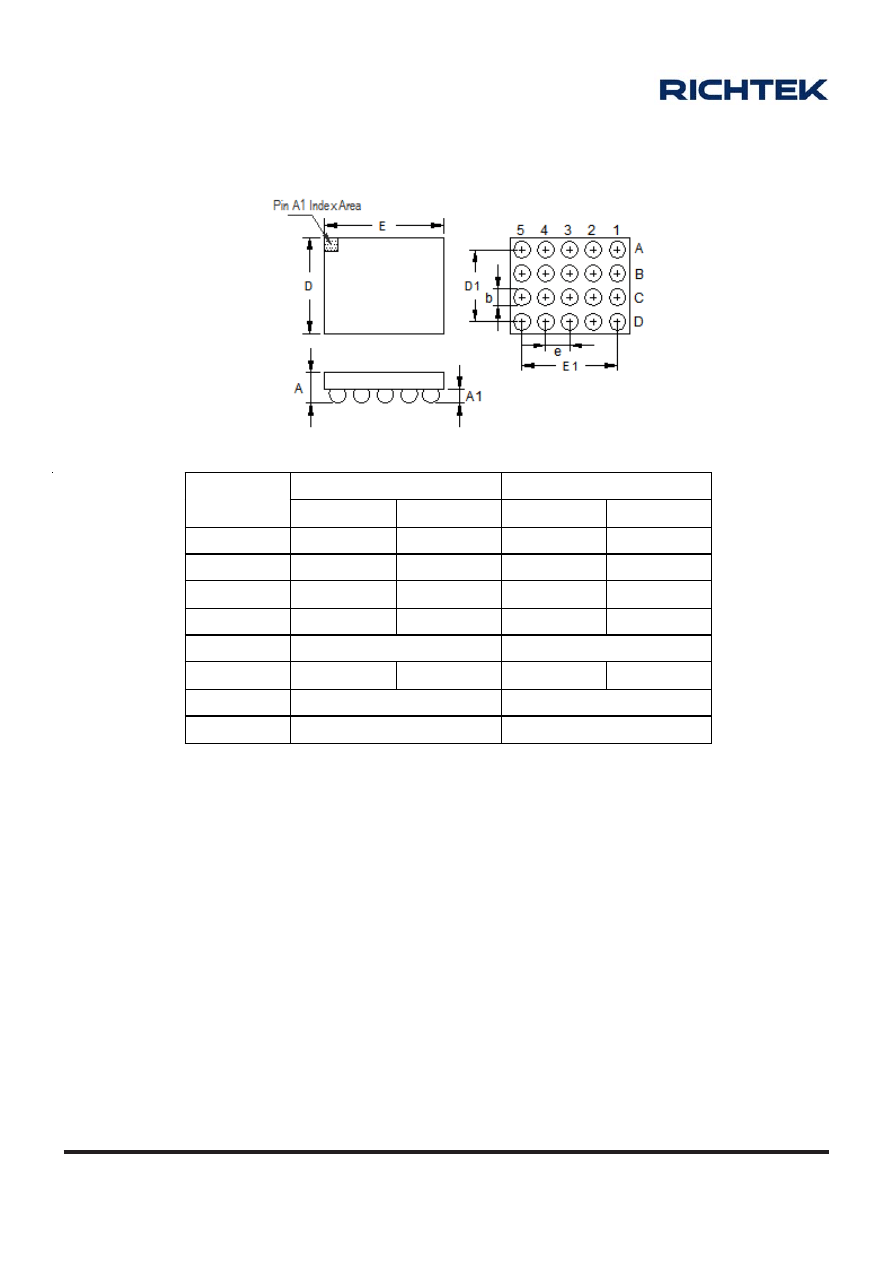
A-130
OD-100330
www.richtek.com
20B WL-CSP 2.45x1.95 Package
Symbol
Dimensions In Millimeters
Dimensions In Inches
Min Max Min Max
A 0.525
0.625
0.021
0.025
A1 0.200
0.260
0.008
0.010
b
0.290 0.350 0.011 0.014
D 1.900
2.000
0.075
0.079
D1 1.500
0.059
E 2.400
2.500
0.094
0.098
E1 2.000
0.079
e 0.500
0.020
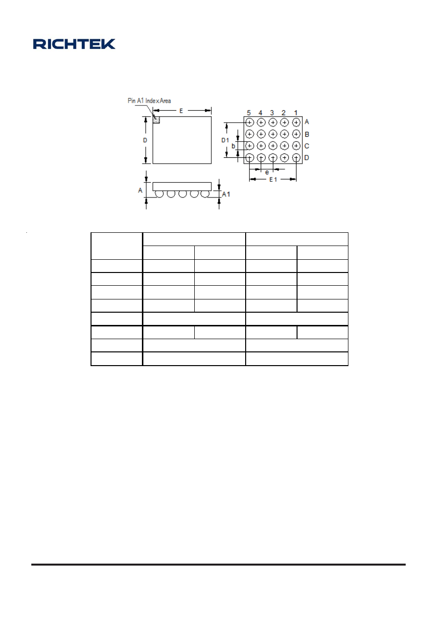
A-131
OD-100330
www.richtek.com
20B WL-CSP 2.55x2.05 Package
Symbol
Dimensions In Millimeters
Dimensions In Inches
Min Max Min Max
A 0.525 0.625 0.021 0.025
A1 0.200 0.260 0.008 0.010
b 0.290
0.350
0.011
0.014
D 2.000 2.100 0.079 0.083
D1 1.500
0.059
E 2.500 2.600 0.098 0.102
E1 2.000
0.079
e 0.500
0.020
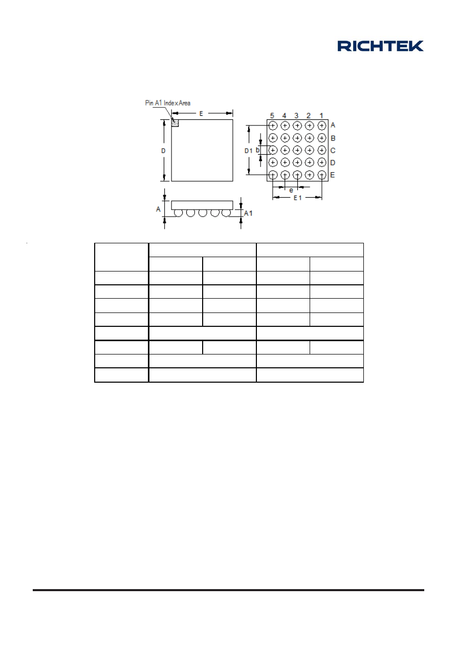
A-132
OD-100330
www.richtek.com
25B WL-CSP 2.45x2.45 Package
Symbol
Dimensions In Millimeters
Dimensions In Inches
Min Max Min Max
A 0.525 0.625 0.021 0.025
A1 0.200 0.260 0.008 0.010
b 0.290
0.350
0.011
0.014
D 2.400 2.500 0.094 0.098
D1 2.000
0.079
E 2.400 2.500 0.094 0.098
E1 2.000
0.079
e 0.500
0.020
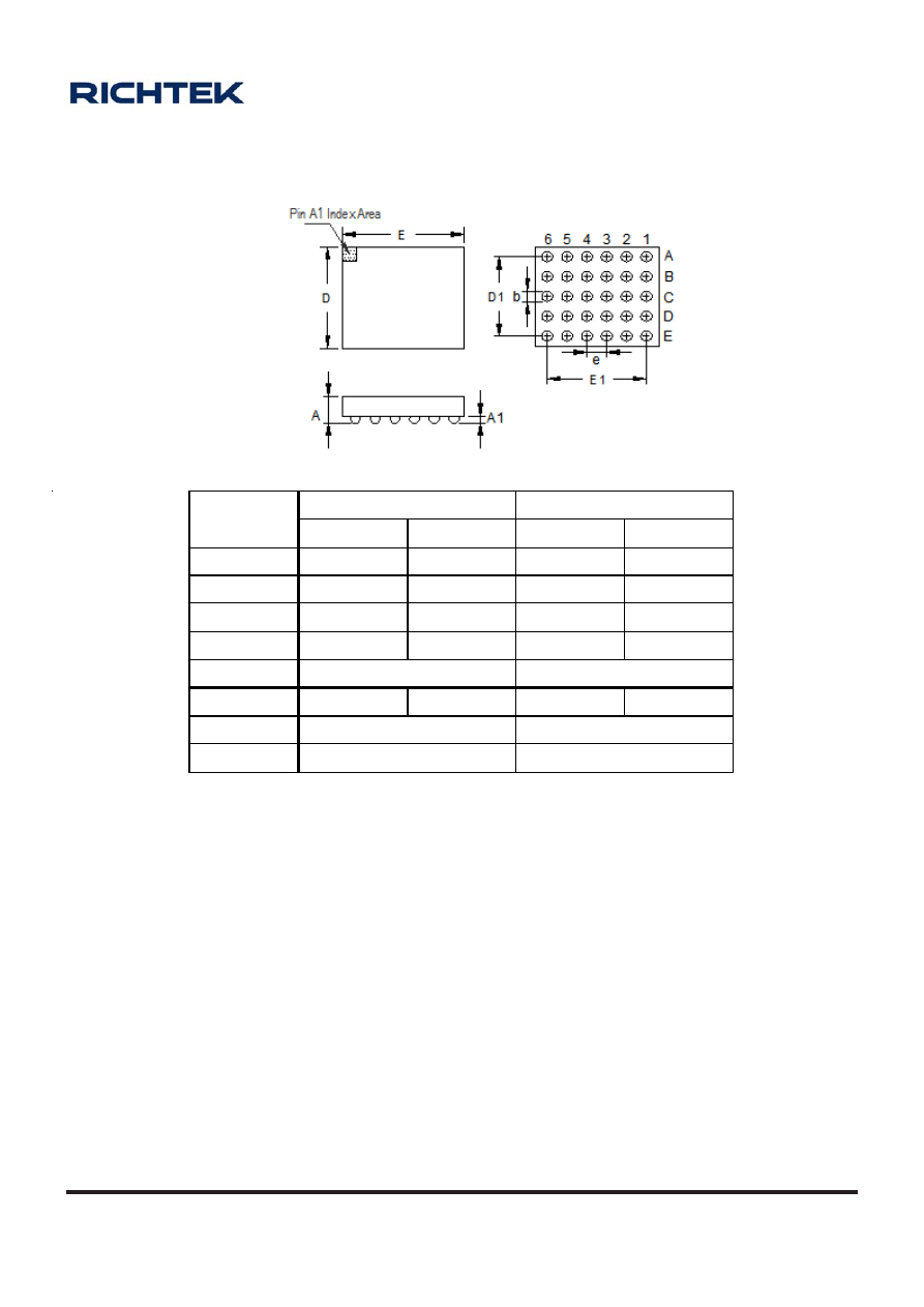
A-133
OD-100330
www.richtek.com
30B WL-CSP 2.45x2.05 Package
Symbol
Dimensions In Millimeters
Dimensions In Inches
Min Max Min Max
A 0.500 0.600 0.020 0.024
A1 0.130 0.180 0.005 0.007
b 0.180 0.250 0.007 0.010
D 2.000 2.100 0.079 0.083
D1 1.600
0.063
E 2.400 2.500 0.094 0.098
E1 2.000
0.079
e 0.400
0.016
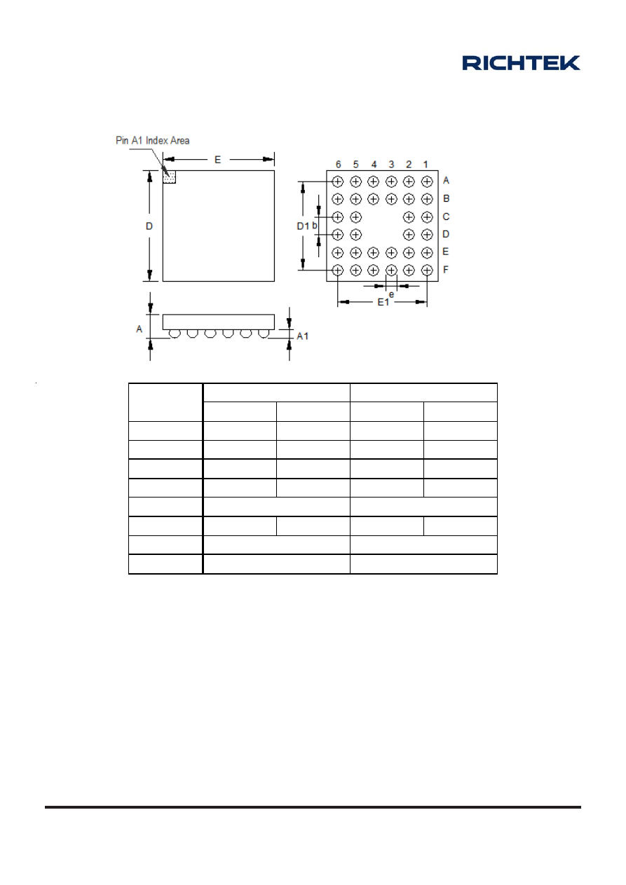
A-134
OD-100330
www.richtek.com
32B WL-CSP 2.4x2.4 Package
Symbol
Dimensions In Millimeters
Dimensions In Inches
Min Max Min Max
A 0.500 0.600 0.020 0.024
A1 0.130 0.180 0.005 0.007
b 0.180 0.250 0.007 0.010
D 2.350 2.450 0.093 0.096
D1 2.000
0.079
E 2.350 2.450 0.093 0.096
E1 2.000
0.079
e 0.400
0.016
Wyszukiwarka
Podobne podstrony:
KB04 SMD DISPLAY
407 B1HG7QK1 Demontaz montaz Pokrywka wlewu paliwa Obudowa pokrywy wlewu paliwa Nieznany
Eksploatacja obudów zmechanizowanych, górnictwo, maszyny i urządzenia
2377 Moje pierwsze SMD id 30349 Nieznany (2)
obudowy zmechanizowane
8 Charakterystyka obudowy chodnika Aw
obudowa łukowo podatna obliczenia projektowe
Obudowa akwarium wraz z miejscem na świetlówki, AKWARYSTYKA
Obudowa kotwiowa, AGH, TPEZ II
Obudowa wyrobisk
stasica obudowadarek
obudowy glosnikowe
Subwoofer w obudowie zamkniętej
X 9 OBUDOWY STOSOWANE W BUDOWNICTWIE PODZIEMNYM
Instrukcja drgania 1, Automatyka i robotyka air pwr, VI SEMESTR, Syst. monit. i diagn. w przem, Mate
ODRZWIA OBUDOWY ŁUKOWEJ PODATNEJ ŁP, kopia pracy
Obudowa wyrobisk górniczych
więcej podobnych podstron