
AV-1
AUDIO, VISUAL, NAVIGATION & TELEPHONE SYS-
TEM
K ELECTRICAL
CONTENTS
C
D
E
F
G
H
I
J
L
M
SECTION
AV
A
B
AV
Revision: November 2005
2005 Frontier
PRECAUTIONS .......................................................... 3
PREPARATION ........................................................... 4
Commercial Service Tool ......................................... 4
AUDIO ......................................................................... 5
Component Parts and Harness Connector Location
System Description .................................................. 6
BASE SYSTEM ..................................................... 6
PREMIUM SYSTEM (KING CAB) ......................... 6
PREMIUM SYSTEM (CREW CAB) ....................... 6
SPEED SENSITIVE VOLUME SYSTEM .............. 7
Schematic ................................................................ 8
PREMIUM SYSTEM (CREW CAB) ....................... 8
Wiring Diagram — AUDIO — ................................... 9
BASE SYSTEM ..................................................... 9
PREMIUM SYSTEM (KING CAB) ........................11
PREMIUM SYSTEM (CREW CAB) ..................... 13
Terminals and Reference Value for Audio Unit (Base
System) .................................................................. 20
Terminals and Reference Value for Audio Unit [Pre-
mium System (King Cab)] ...................................... 21
Terminals and Reference Value for Audio Unit [Pre-
mium System (Crew Cab)] ..................................... 22
Terminals and Reference Value for Audio Amplifier
[Premium System (Crew Cab)] .............................. 25
Audio Unit Self-Diagnosis Function (Premium Sys-
tem) ........................................................................ 28
Trouble Diagnosis .................................................. 29
Noise Inspection ..................................................... 30
TYPE OF NOISE AND POSSIBLE CAUSE ........ 31
Power Supply Circuit Inspection ............................. 31
Steering Switch Check (Premium System) ............. 32
Sound Is Not Heard From Front Door Speaker or
Front Tweeter (Base System) ................................. 35
Sound Is Not Heard From Rear Door Speaker (Base
System) .................................................................. 37
Sound Is Not Heard From Front Door Speaker or
Front Tweeter [Premium System (King Cab)] ......... 39
Sound Is Not Heard From Rear Door Speaker [Pre-
mium System (King Cab)] ....................................... 41
Sound Is Not Heard From Front Door Speaker or
Front Tweeter [Premium System (Crew Cab)] ........ 43
Sound Is Not Heard From Rear Door Speaker or
Rear Door Tweeter [Premium System (Crew Cab)]
Sound Is Not Heard From Subwoofer [Premium
System (Crew Cab)] ............................................... 50
Removal and Installation for Audio Unit ................. 51
Removal and Installation of Speaker ...................... 51
REMOVAL - FRONT DOOR SPEAKER .............. 51
INSTALLATION - FRONT DOOR SPEAKER ...... 51
REMOVAL - REAR DOOR SPEAKER ................ 51
INSTALLATION - REAR DOOR SPEAKER ........ 51
REMOVAL - FRONT TWEETER ......................... 51
INSTALLATION - FRONT TWEETER ................. 52
REMOVAL - REAR DOOR TWEETER - CREW
CAB ..................................................................... 52
INSTALLATION - REAR DOOR TWEETER -
CREW CAB ......................................................... 52
REMOVAL - SUBWOOFER (PREMIUM SYS-
TEM) - CREW CAB ............................................. 52
INSTALLATION - SUBWOOFER (PREMIUM
SYSTEM) - CREW CAB ...................................... 53

AV-2
Revision: November 2005
2005 Frontier
REMOVAL ........................................................... 53
INSTALLATION .................................................... 54
AUDIO ANTENNA .....................................................55

PRECAUTIONS
AV-3
C
D
E
F
G
H
I
J
L
M
A
B
AV
Revision: November 2005
2005 Frontier
PRECAUTIONS
PFP:00001
Precautions for Supplemental Restraint System (SRS) “AIR BAG” and “SEAT
BELT PRE-TENSIONER”
EKS00BYX
The Supplemental Restraint System such as “AIR BAG” and “SEAT BELT PRE-TENSIONER”, used along
with a front seat belt, helps to reduce the risk or severity of injury to the driver and front passenger for certain
types of collision. This system includes seat belt switch inputs and dual stage front air bag modules. The SRS
system uses the seat belt switches to determine the front air bag deployment, and may only deploy one front
air bag, depending on the severity of a collision and whether the front occupants are belted or unbelted.
Information necessary to service the system safely is included in the SRS and SB section of this Service Man-
ual.
WARNING:
●
To avoid rendering the SRS inoperative, which could increase the risk of personal injury or death
in the event of a collision which would result in air bag inflation, all maintenance must be per-
formed by an authorized NISSAN/INFINITI dealer.
●
Improper maintenance, including incorrect removal and installation of the SRS, can lead to per-
sonal injury caused by unintentional activation of the system. For removal of Spiral Cable and Air
Bag Module, see the SRS section.
●
Do not use electrical test equipment on any circuit related to the SRS unless instructed to in this
Service Manual. SRS wiring harnesses can be identified by yellow and/or orange harnesses or
harness connectors.
Wiring Diagrams and Trouble Diagnosis
EKS00BYY
When you read wiring diagrams, refer to the following:
●
GI-17, "How to Read Wiring Diagrams"
.
●
PG-4, "POWER SUPPLY ROUTING CIRCUIT"
.
When you perform trouble diagnosis, refer to the following:
●
GI-13, "HOW TO FOLLOW TEST GROUPS IN TROUBLE DIAGNOSES"
●
GI-29, "How to Perform Efficient Diagnosis for an Electrical Incident"

AV-4
PREPARATION
Revision: November 2005
2005 Frontier
PREPARATION
PFP:00002
Commercial Service Tool
EKS00BYZ
Tool name
Description
Power tool
Loosening bolts and nuts
PBIC0191E
AUDIO
AV-5
C
D
E
F
G
H
I
J
L
M
A
B
AV
Revision: November 2005
2005 Frontier
AUDIO
PFP:28111
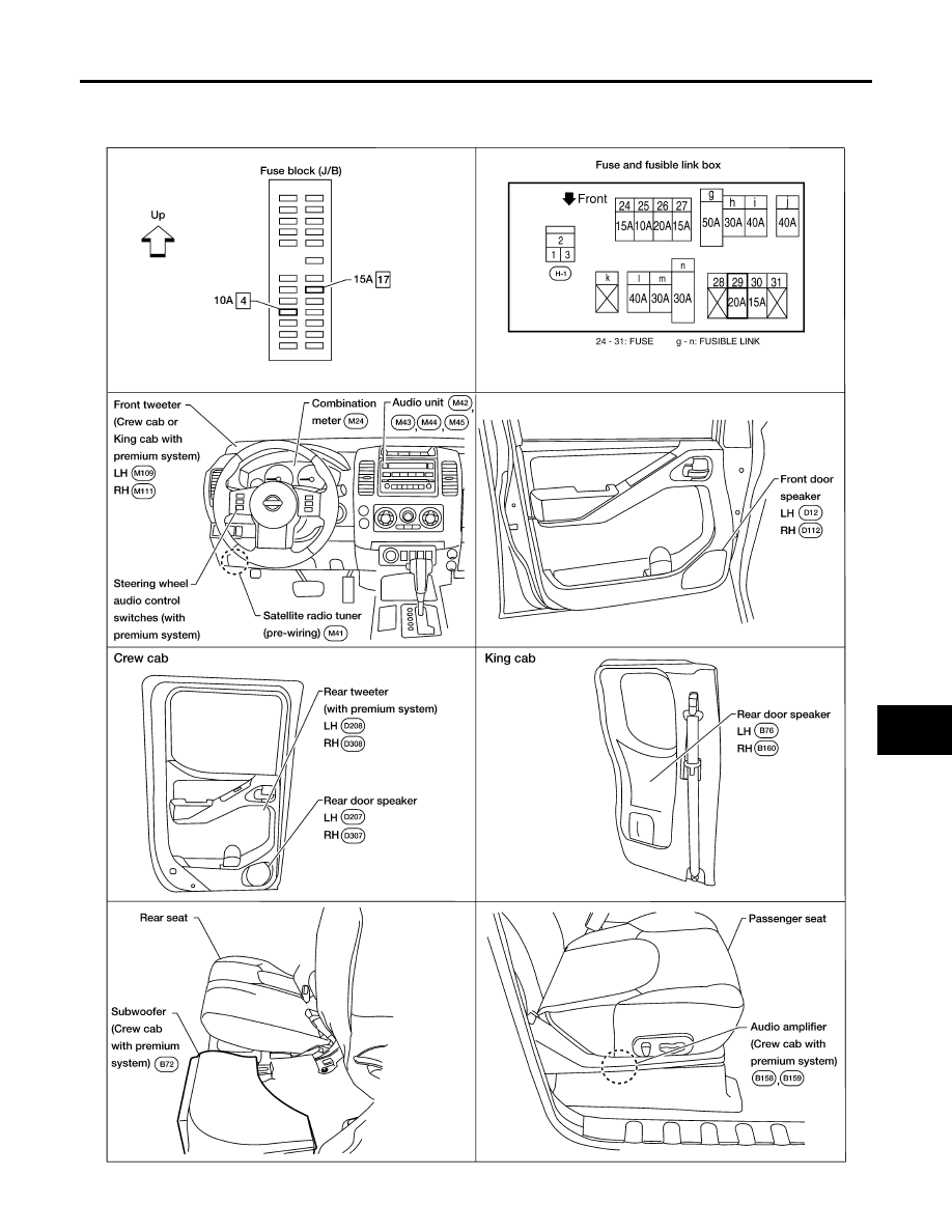
Component Parts and Harness Connector Location
EKS00BZ0
WKIA3995E

AV-6
AUDIO
Revision: November 2005
2005 Frontier
System Description
EKS00BZ1
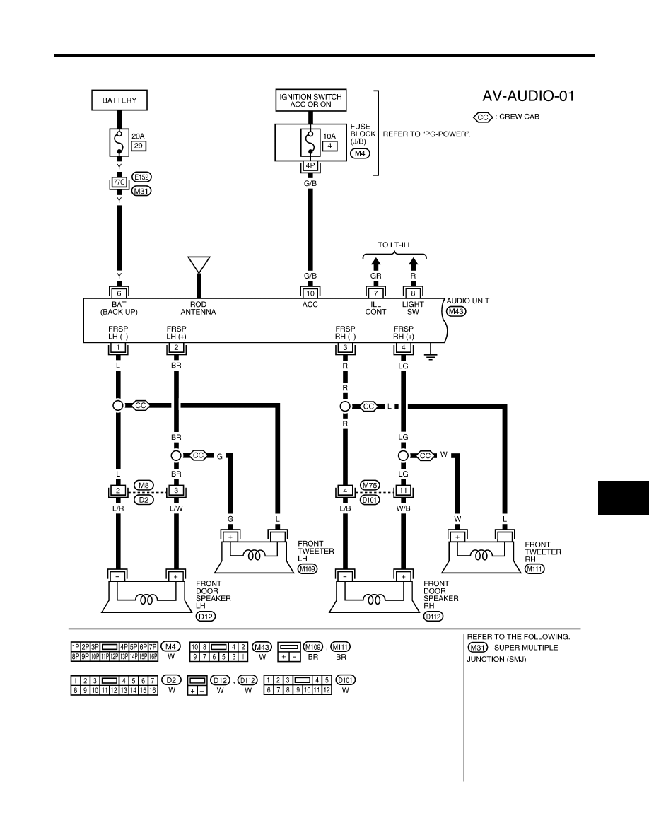
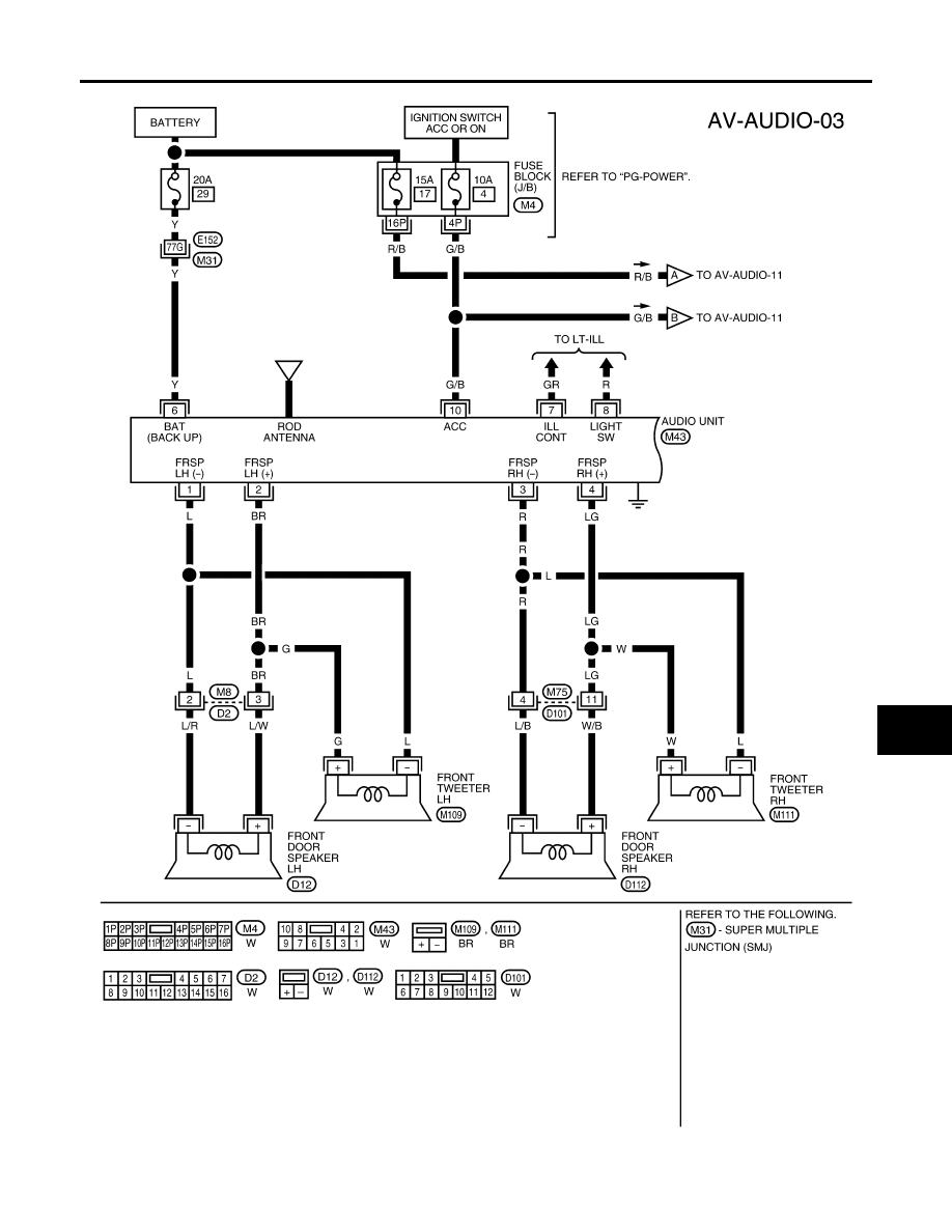
BASE SYSTEM
Refer to Owner's Manual for audio system operating instructions.
Power is supplied at all times
●
through 20A fuse (No. 29, located in the fuse and fusible link box)
●
to audio unit terminal 6.
With the ignition switch in the ACC or ON position, power is supplied
●
through 10A fuse [No. 4, located in the fuse block (J/B)]
●
to audio unit terminal 10.
Ground is supplied through the case of the audio unit.
Then audio signals are supplied
●
through audio unit terminals 1, 2, 3, 4, 13, 14, 15 and 16
●
to terminals + and - of front door speaker LH and RH
●
to terminals + and - of front tweeter LH and RH (Crew cab)
●
to terminals + and - of rear door speaker LH and RH.
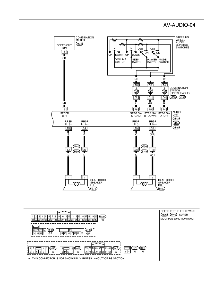
PREMIUM SYSTEM (KING CAB)
Refer to Owner's Manual for audio system operating instructions.
Power is supplied at all times
●
through 20A fuse [No. 29, located in the fuse and fusible link box]
●
to audio unit terminal 6.
With the ignition switch in the ACC or ON position, power is supplied
●
through 10A fuse [No. 4, located in the fuse block (J/B)]
●
to audio unit terminal 10.
Ground is supplied through the case of the audio unit.
Then audio signals are supplied
●
through audio unit terminals 1, 2, 3, 4, 13, 14, 15 and 16
●
to terminals + and - of front door speaker LH and RH
●
to terminals + and - of front tweeter LH and RH
●
to terminals + and - of rear door speaker LH and RH.
When one of steering wheel audio control switches is pushed, the resistance in steering switch circuit changes
depending on which button is pushed.
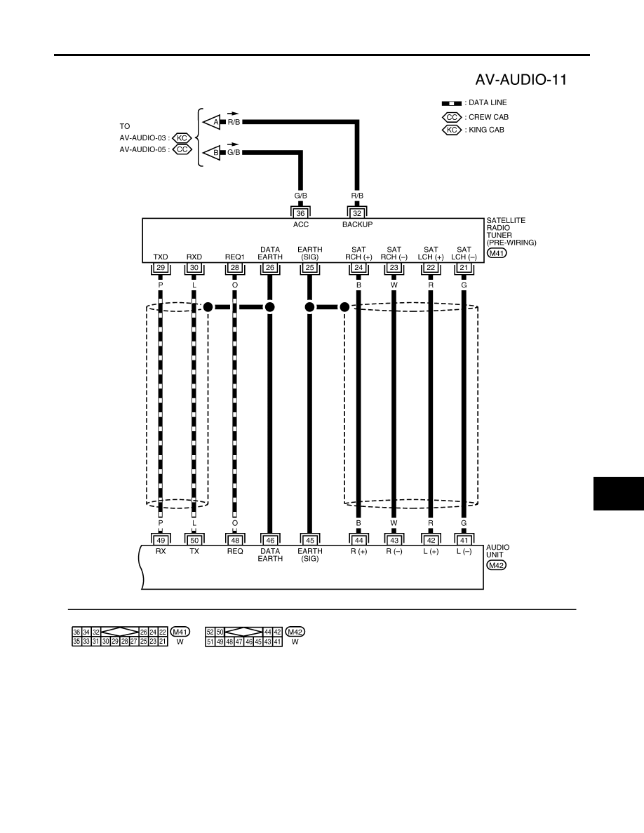
Satellite Radio Tuner (Pre-wiring)
The satellite radio tuner pre-wiring allows connection of a satellite radio tuner.
Power is supplied at all times
●
through 15A fuse [No. 17, located in the fuse block (J/B)]
●
to satellite radio tuner pre-wiring terminal 32.
With the ignition switch in the ACC or ON position, power is supplied
●
through 10A fuse [No. 4, located in the fuse block (J/B)]
●
to satellite radio tuner pre-wiring terminal 36.
Ground is supplied
●
to satellite radio tuner (pre-wiring) terminals 25 and 26
●
from audio unit terminals 45 and 46.
Then audio signals are supplied
●
through satellite radio tuner pre-wiring terminals 21, 22, 23 and 24
●
to audio unit terminals 41, 42, 43 and 44.
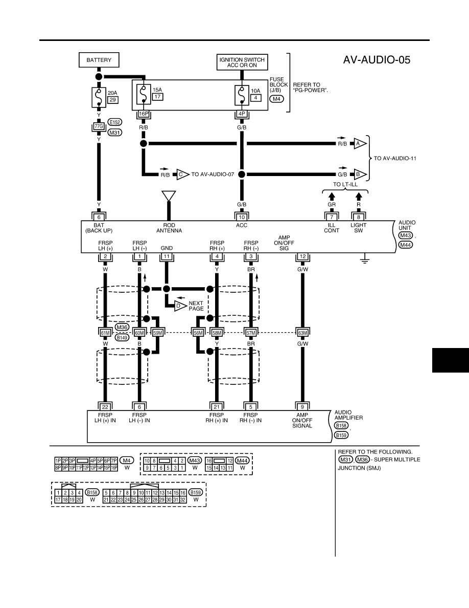
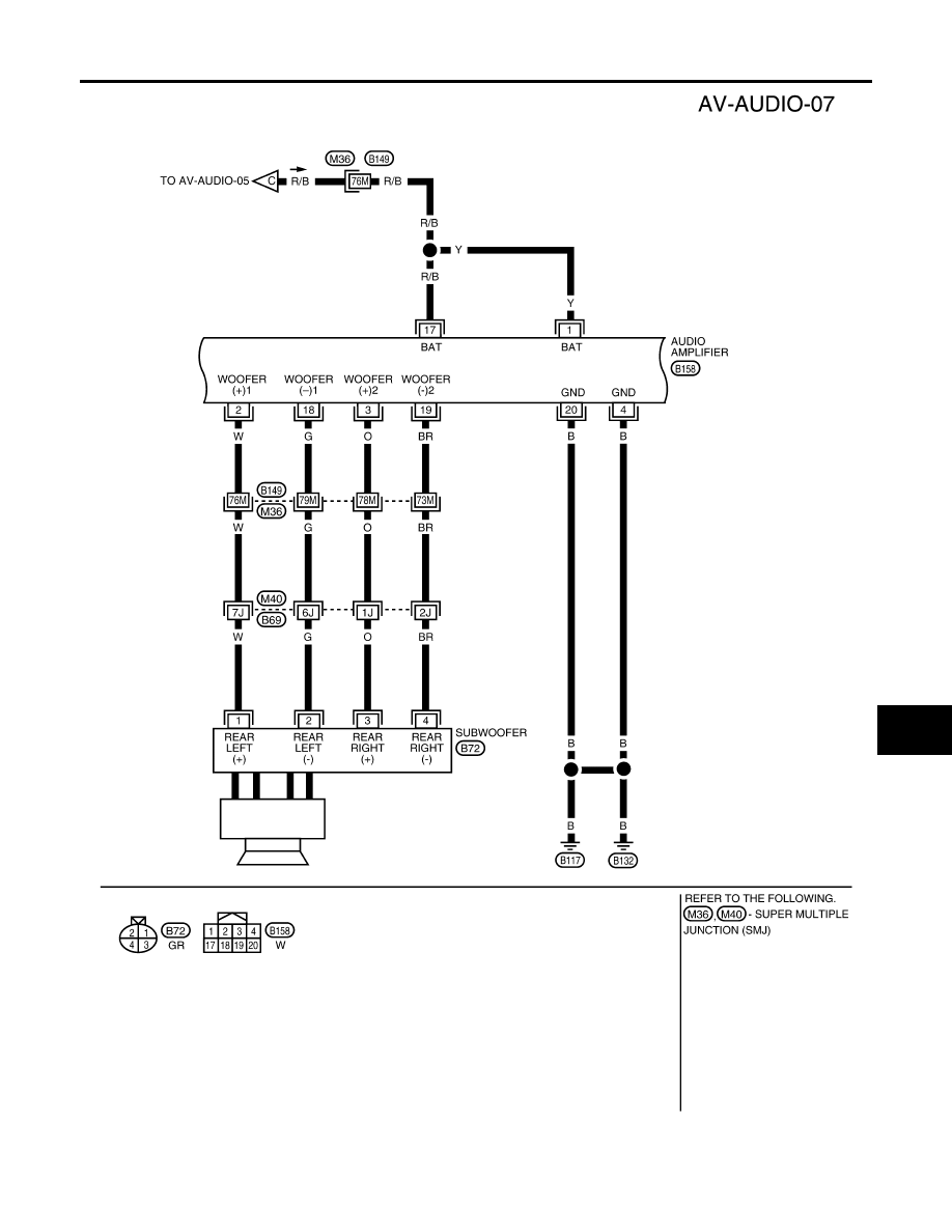
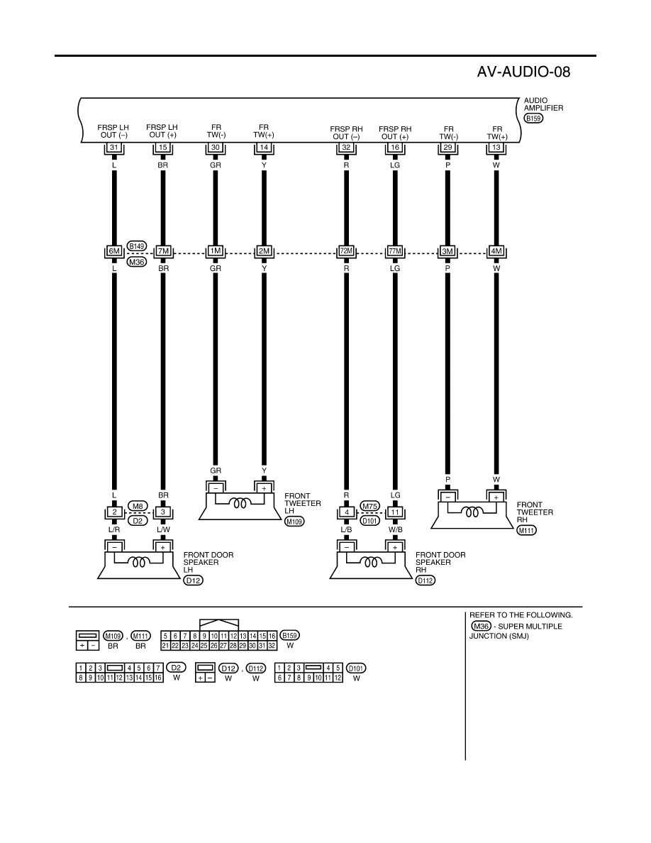
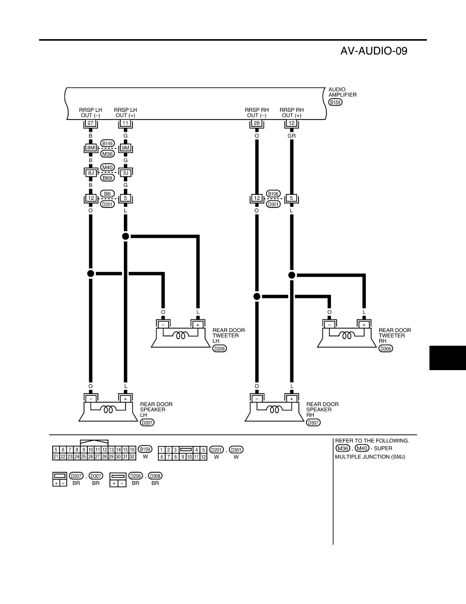
PREMIUM SYSTEM (CREW CAB)
Refer to Owner's Manual for audio system operating instructions.
Power is supplied at all times
●
through 15A fuse [No. 17, located in the fuse block (J/B)]

AUDIO
AV-7
C
D
E
F
G
H
I
J
L
M
A
B
AV
Revision: November 2005
2005 Frontier
●
to audio amplifier terminals 1 and 17
●
through 20A fuse [No. 29, located in the fuse and fusible link box]
●
to audio unit terminal 6.
With the ignition switch in the ACC or ON position, power is supplied
●
through 10A fuse [No. 4, located in the fuse block (J/B)]
●
to audio unit terminal 10.
Ground is supplied through the case of the audio unit.
Ground is also supplied
●
to audio amplifier terminals 4 and 20
●
through body grounds B7 and B19.
Then audio signals are supplied
●
through audio unit terminals 1, 2, 3, 4, 13, 14, 15 and 16
●
to audio amplifier terminals 5, 6, 7, 8, 21, 22, 23 and 24.
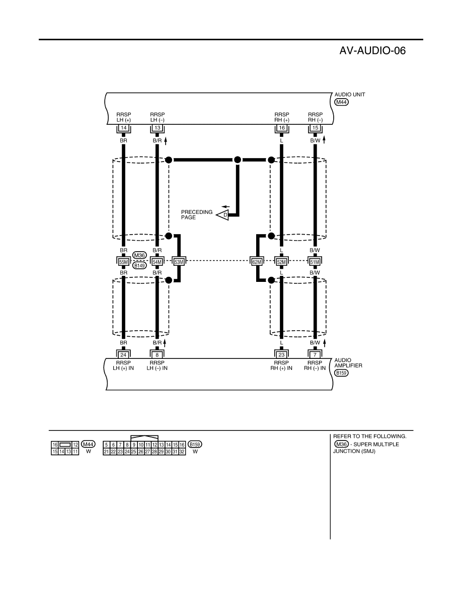
Audio signals are amplified by the audio amplifier
The amplified audio signals are supplied
●
through audio amplifier terminals 2, 3, 11, 12, 13, 14, 15, 16, 18, 19, 27, 28, 29, 30, 31 and 32
●
to terminals + and - of front door speaker LH and RH
●
to terminals + and - of front tweeter LH and RH
●
to terminals + and - of rear door speaker LH and RH
●
to terminals + and - of rear door tweeter LH and RH
●
to terminals 1, 2, 3 and 4 of subwoofer.
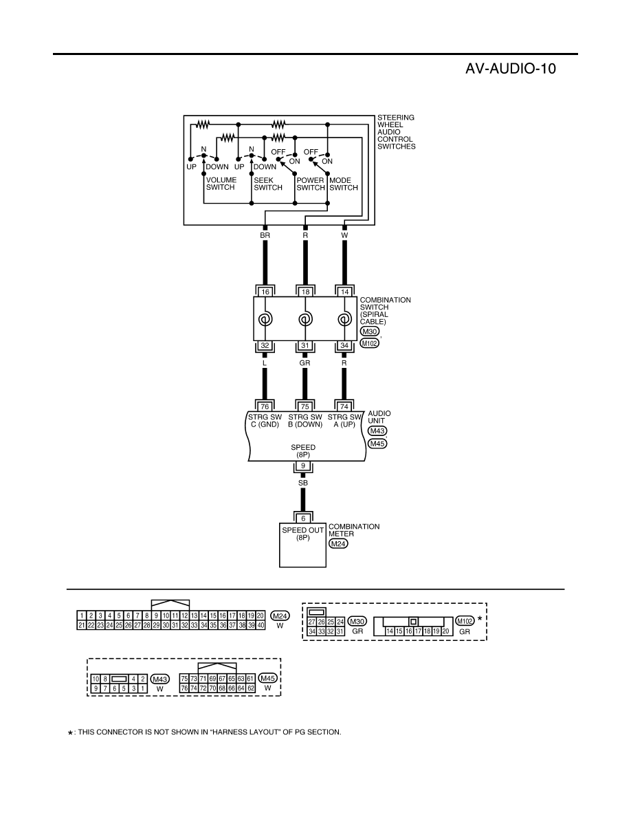
When one of steering wheel audio control switches is pushed, the resistance in steering switch circuit changes
depending on which button is pushed.
Satellite Radio Tuner (Pre-wiring)
The satellite radio tuner pre-wiring allows connection of a satellite radio tuner.
Power is supplied at all times
●
through 15A fuse [No. 17, located in the fuse block (J/B)]
●
to satellite radio tuner pre-wiring terminal 32.
With the ignition switch in the ACC or ON position, power is supplied
●
through 10A fuse [No. 4, located in the fuse block (J/B)]
●
to satellite radio tuner pre-wiring terminal 36.
Ground is supplied
●
to satellite radio tuner (pre-wiring) terminals 25 and 26
●
from audio unit terminals 45 and 46.
Then audio signals are supplied
●
through satellite radio tuner pre-wiring terminals 21, 22, 23 and 24
●
to audio unit terminals 41, 42, 43 and 44.
SPEED SENSITIVE VOLUME SYSTEM
Volume level of this system goes up and down automatically in proportion to the vehicle speed. The control
level can be selected by the customer. Refer to Owner's Manual for operating instructions.
AV-8
AUDIO
Revision: November 2005
2005 Frontier
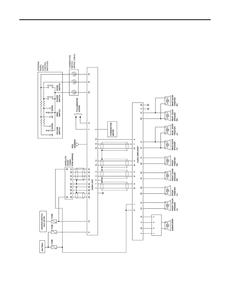
Schematic
EKS00BZ2
PREMIUM SYSTEM (CREW CAB)
WKWA2817E
AUDIO
AV-9
C
D
E
F
G
H
I
J
L
M
A
B
AV
Revision: November 2005
2005 Frontier
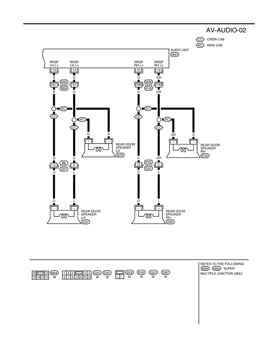
Wiring Diagram — AUDIO —
EKS00BZ3
BASE SYSTEM
WKWA2095E
AV-10
AUDIO
Revision: November 2005
2005 Frontier
WKWA2096E
AUDIO
AV-11
C
D
E
F
G
H
I
J
L
M
A
B
AV
Revision: November 2005
2005 Frontier
PREMIUM SYSTEM (KING CAB)
WKWA2098E
AV-12
AUDIO
Revision: November 2005
2005 Frontier
WKWA2099E
AUDIO
AV-13
C
D
E
F
G
H
I
J
L
M
A
B
AV
Revision: November 2005
2005 Frontier
PREMIUM SYSTEM (CREW CAB)
WKWA2818E
AV-14
AUDIO
Revision: November 2005
2005 Frontier
WKWA2103E
AUDIO
AV-15
C
D
E
F
G
H
I
J
L
M
A
B
AV
Revision: November 2005
2005 Frontier
WKWA2819E
AV-16
AUDIO
Revision: November 2005
2005 Frontier
WKWA2105E
AUDIO
AV-17
C
D
E
F
G
H
I
J
L
M
A
B
AV
Revision: November 2005
2005 Frontier
WKWA2106E
AV-18
AUDIO
Revision: November 2005
2005 Frontier
WKWA2107E
AUDIO
AV-19
C
D
E
F
G
H
I
J
L
M
A
B
AV
Revision: November 2005
2005 Frontier
SATELLITE RADIO TUNER (PRE-WIRING)
WKWA2820E
AV-20
AUDIO
Revision: November 2005
2005 Frontier
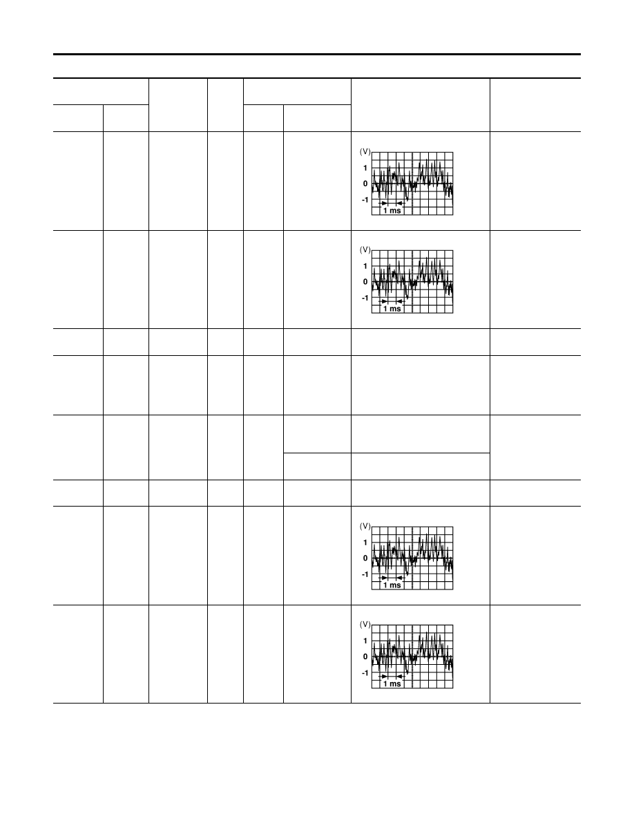
Terminals and Reference Value for Audio Unit (Base System)
EKS00BZ4
*: Crew cab
Terminal
(Wire color)
Item
Signal
input/
output
Condition
Reference value
(Approx.)
Example of symptom
+
–
Ignition
switch
Operation
2 (BR)
1 (L)
Audio sound
signal front
LH
Output
ON
Receive audio
signal
No sound from front
door speaker LH or
tweeter LH*.
4 (LG)
3 (R)
Audio sound
signal front
RH
Output
ON
Receive audio
signal
No sound from front
door speaker RH or
tweeter RH*.
6 (Y)
Ground
Battery
power
Input
–
–
Battery voltage
System does not
work properly.
7 (GR)
Ground
Illumination
control sig-
nal
Input
ON
Illumination
control switch
is operated by
lighting switch
in 1st position.
Changes between 0 and 12V
Audio unit illumina-
tion cannot be con-
trolled.
8 (R)
Ground
Illumination
signal
Input
OFF
Lighting switch
is in 1st posi-
tion.
Battery voltage
Audio unit illumina-
tion does not come
on when lighting
switch is in 1st posi-
tion.
Lighting switch
is OFF.
3V or less
10 (G/B)
Ground
ACC signal
Input
ON
Ignition switch
ACC or ON
Battery voltage
System does not
work properly.
14 (G)
13 (B)
Audio sound
signal rear
LH
Output
ON
Receive audio
signal
No sound from rear
door speaker LH.
16 (GR)
15 (O)
Audio sound
signal rear
RH
Output
ON
Receive audio
signal
No sound from rear
door speaker RH.
SKIA0177E
SKIA0177E
SKIA0177E
SKIA0177E
AUDIO
AV-21
C
D
E
F
G
H
I
J
L
M
A
B
AV
Revision: November 2005
2005 Frontier
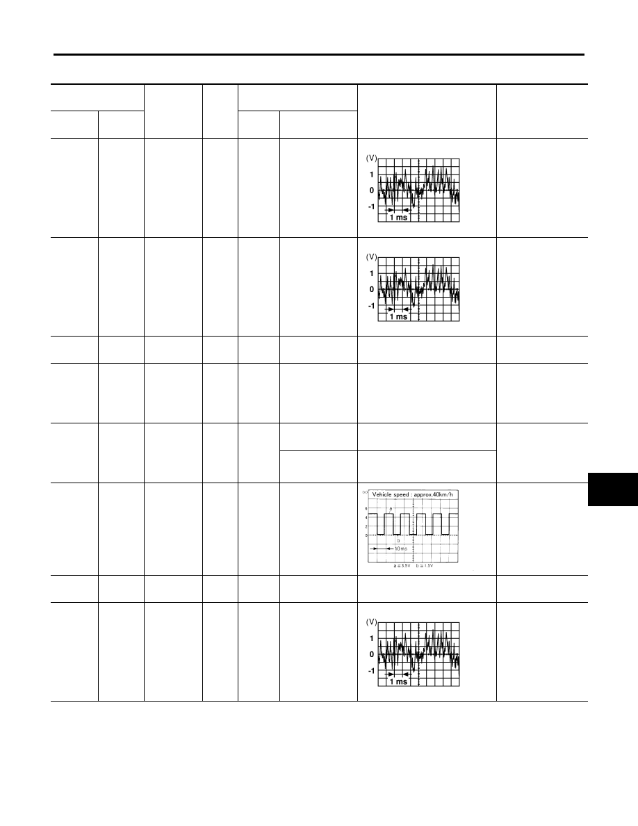
Terminals and Reference Value for Audio Unit [Premium System (King Cab)]
EKS00C2V
Terminal
(Wire color)
Item
Signal
input/
output
Condition
Reference value
(Approx.)
Example of symptom
+
–
Ignition
switch
Operation
2 (BR)
1 (L)
Audio sound
signal front
LH
Output
ON
Receive audio
signal
No sound from front
door speaker LH or
tweeter LH.
4 (LG)
3 (R)
Audio sound
signal front
RH
Output
ON
Receive audio
signal
No sound from front
door speaker RH or
tweeter RH.
6 (Y)
Ground
Battery
power
Input
–
–
Battery voltage
System does not
work properly.
7 (GR)
Ground
Illumination
control sig-
nal
Input
ON
Illumination con-
trol switch is
operated by light-
ing switch in 1st
position.
Changes between 0 and 12V
Audio unit illumina-
tion cannot be con-
trolled.
8 (R)
Ground
Illumination
signal
Input
OFF
Lighting switch is
in 1st position.
Battery voltage
Audio unit illumina-
tion does not come
on when lighting
switch is in 1st posi-
tion.
Lighting switch is
OFF.
3V or less
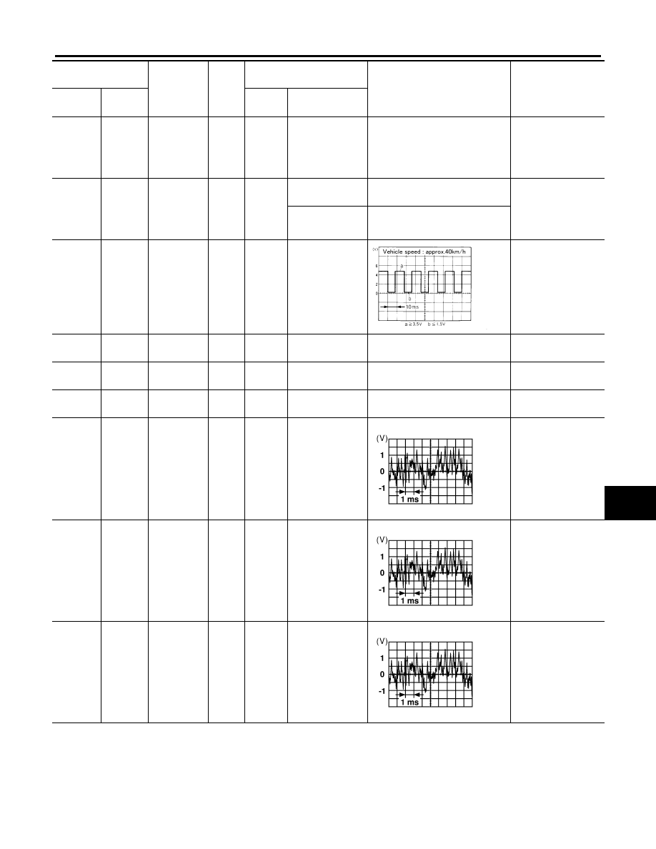
9 (SB)
Ground
Vehicle
speed sig-
nal
Input
ON
When vehicle
speed is approx.
40 km/h (25
MPH)
Speed sensitive vol-
ume inoperative.
10 (G/B)
Ground
ACC signal
Input
ON
–
Battery voltage
System does not
work properly.
14 (G)
13 (B)
Audio sound
signal rear
LH
Output
ON
Receive audio
signal
No sound from rear
door speaker LH.
SKIA0177E
SKIA0177E
SKIA0168E
SKIA0177E
AV-22
AUDIO
Revision: November 2005
2005 Frontier
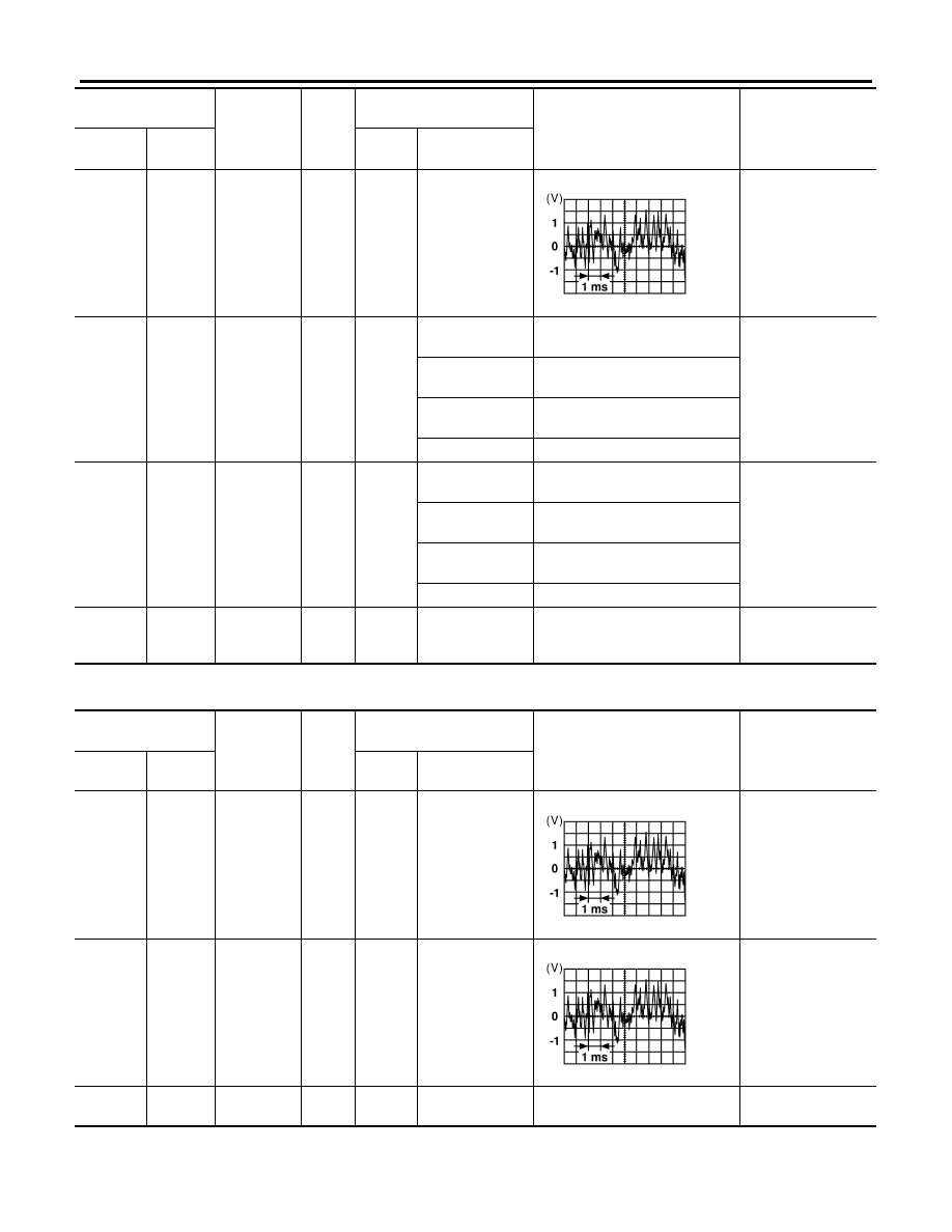
Terminals and Reference Value for Audio Unit [Premium System (Crew Cab)]
EKS00BZ5
16 (G/R)
15 (O)
Audio sound
signal rear
RH
Output
ON
Receive audio
signal
No sound from rear
door speaker RH.
74 (R)
Ground
Remote
control A
Input
ON
Press MODE
switch
0V
Steering wheel audio
controls do not func-
tion.
Press SEEK UP
switch
0.75V
Press VOL UP
switch
2V
Except for above
5V
75 (GR)
Ground
Remote
control B
Input
ON
Press POWER
switch
0V
Steering wheel audio
controls do not func-
tion.
Press SEEK
DOWN switch
0.75V
Press VOL
DOWN switch
2V
Except for above
5V
76 (L)
–
Remote
control
ground
–
–
–
–
Steering wheel audio
controls do not func-
tion.
Terminal
(Wire color)
Item
Signal
input/
output
Condition
Reference value
(Approx.)
Example of symptom
+
–
Ignition
switch
Operation
SKIA0177E
Terminal
(Wire color)
Item
Signal
input/
output
Condition
Reference value
(Approx.)
Example of symptom
+
–
Ignition
switch
Operation
2 (W)
1 (B)
Audio sound
signal front
LH
Output
ON
Receive audio
signal
No sound from front
door speaker LH or
tweeter LH.
4 (Y)
3 (BR)
Audio sound
signal front
RH
Output
ON
Receive audio
signal
No sound from front
door speaker RH or
tweeter RH.
6 (Y)
Ground
Battery
power
Input
–
–
Battery voltage
System does not
work properly.
SKIA0177E
SKIA0177E
AUDIO
AV-23
C
D
E
F
G
H
I
J
L
M
A
B
AV
Revision: November 2005
2005 Frontier
7 (GR)
Ground
Illumination
control sig-
nal
Input
ON
Illumination con-
trol switch is
operated by light-
ing switch in 1st
position.
Changes between 0 and 12V
Audio unit illumina-
tion cannot be con-
trolled.
8 (R)
Ground
Illumination
signal
Input
OFF
Lighting switch is
in 1st position.
Battery voltage
Audio unit illumina-
tion does not come
on when lighting
switch is in 1st posi-
tion.
Lighting switch is
OFF.
3V or less
9 (SB)
Ground
Vehicle
speed sig-
nal
Input
ON
When vehicle
speed is approx.
40 km/h (25
MPH)
Speed sensitive vol-
ume inoperative.
10 (G/B)
Ground
ACC signal
Input
ON
–
Battery voltage
System does not
work properly.
11
–
Shield
ground
–
–
–
–
–
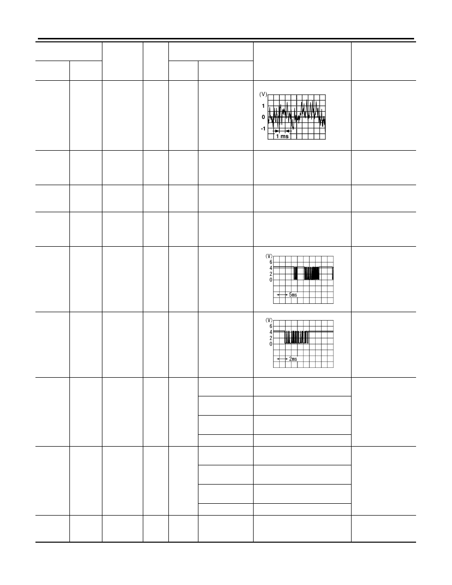
12 (G/W)
Ground
Amp. ON
signal
Output
ON
–
More than 6.5V
Audio amplifier does
not work properly.
14 (BR)
13 (B/R)
Audio sound
signal rear
LH
Output
ON
Receive audio
signal
No sound from rear
door speaker LH or
rear door tweeter LH.
16 (L)
15 (B/W)
Audio sound
signal rear
RH
Output
ON
Receive audio
signal
No sound from rear
door speaker RH or
rear door tweeter
RH.
42 (R)
41 (G)
Audio left
channel
sound sig-
nal from sat-
ellite radio
tuner
Input
ON
Receive audio
signal
No sound from satel-
lite radio tuner left
channel.
Terminal
(Wire color)
Item
Signal
input/
output
Condition
Reference value
(Approx.)
Example of symptom
+
–
Ignition
switch
Operation
SKIA0168E
SKIA0177E
SKIA0177E
SKIA0177E
AV-24
AUDIO
Revision: November 2005
2005 Frontier
44 (B)
43 (W)
Audio right
channel
sound sig-
nal from sat-
ellite radio
tuner
Input
ON
Receive audio
signal
No sound from satel-
lite radio tuner right
channel.
45
–
Shield
ground
(audio sig-
nal)
–
–
–
–
–
46
–
Shield
ground
(data)
–
–
–
–
–
48 (O)
Ground
Satellite
radio tuner
request to
audio unit
Input
ON
Turn audio unit
ON
5V
Satellite radio tuner
does not operate
properly.
49 (P)
Ground
Audio RX
Input
ON
Operate audio
volume
Satellite radio tuner
audio information
does not display
properly.
50 (L)
Ground
Audio TX
Output
ON
Operate audio
volume
Satellite radio tuner
audio information
does not display
properly.
74 (R)
Ground
Remote
control A
Input
ON
Press MODE
switch
0V
Steering wheel audio
controls do not func-
tion.
Press SEEK UP
switch
0.75V
Press VOL UP
switch
2V
Except for above
5V
75 (GR)
Ground
Remote
control B
Input
ON
Press POWER
switch
0V
Steering wheel audio
controls do not func-
tion.
Press SEEK
DOWN switch
0.75V
Press VOL
DOWN switch
2V
Except for above
5V
76 (L)
–
Remote
control
ground
–
–
–
–
Steering wheel audio
controls do not func-
tion.
Terminal
(Wire color)
Item
Signal
input/
output
Condition
Reference value
(Approx.)
Example of symptom
+
–
Ignition
switch
Operation
SKIA0177E
SKIA4403E
SKIA4402E
AUDIO
AV-25
C
D
E
F
G
H
I
J
L
M
A
B
AV
Revision: November 2005
2005 Frontier
Terminals and Reference Value for Audio Amplifier [Premium System (Crew
Cab)]
EKS00BZ6
Terminal
(wire color)
Item
Signal
input/
output
Condition
Reference value
(Approx.)
Example of
symptom
+
–
Ignition
switch
Operation
1 (Y)
Ground
Battery
Input
–
–
Battery voltage
System does not
work properly.
2 (W)
18 (G)
Subwoofer
Output
ON
Receive audio
signal
No sound from
subwoofer.
3 (O)
19 (BR)
Subwoofer
Output
ON
Receive audio
signal
No sound from
subwoofer.
4 (B)
Ground
Ground
–
ON
–
–
–
9 (G/W)
Ground
Amp. ON sig-
nal
Input
ON
–
More than 6.5V
System does not
work properly.
11 (G)
27 (B)
Rear door
speaker LH
and rear door
tweeter LH
Output
ON
Receive audio
signal
No sound from
rear door speaker
LH or rear door
tweeter LH.
12 (GR)
28 (O)
Rear door
speaker RH
and rear door
tweeter RH
Output
ON
Receive audio
signal
No sound from
rear door speaker
RH or rear door
tweeter RH.
13 (W)
29 (P)
Front tweeter
RH
Output
ON
Receive audio
signal
No sound from
front tweeter RH.
SKIA0177E
SKIA0177E
SKIA0177E
SKIA0177E
SKIA0177E
AV-26
AUDIO
Revision: November 2005
2005 Frontier
14 (Y)
30 (GR)
Front tweeter
LH
Output
ON
Receive audio
signal
No sound from
front tweeter LH.
15 (BR)
31 (L)
Front door
speaker LH
Output
ON
Receive audio
signal
No sound from
front door speaker
LH.
16 (LG)
32 (R)
Front door
speaker RH
Output
ON
Receive audio
signal
No sound from
front door speaker
RH.
17 (R/B)
Ground
Battery
Input
–
–
Battery voltage
System does not
work properly.
20 (B)
Ground
Ground
–
ON
–
–
–
21 (Y)
5 (BR)
Audio sound
signal front RH
Input
ON
Receive audio
signal
No sound from
front door speaker
RH or front tweeter
RH.
22 (W)
6 (B)
Audio sound
signal front LH
Input
ON
Receive audio
signal
No sound from
front door speaker
LH or front tweeter
LH.
Terminal
(wire color)
Item
Signal
input/
output
Condition
Reference value
(Approx.)
Example of
symptom
+
–
Ignition
switch
Operation
SKIA0177E
SKIA0177E
SKIA0177E
SKIA0177E
SKIA0177E
AUDIO
AV-27
C
D
E
F
G
H
I
J
L
M
A
B
AV
Revision: November 2005
2005 Frontier
23 (L)
7 (B/W)
Audio sound
signal rear RH
Input
ON
Receive audio
signal
No sound from
rear door speaker
RH or rear door
tweeter RH.
24 (BR)
8 (B/R)
Audio sound
signal rear LH
Input
ON
Receive audio
signal
No sound from
rear door speaker
LH or rear door
tweeter LH.
Terminal
(wire color)
Item
Signal
input/
output
Condition
Reference value
(Approx.)
Example of
symptom
+
–
Ignition
switch
Operation
SKIA0177E
SKIA0177E
AV-28
AUDIO
Revision: November 2005
2005 Frontier
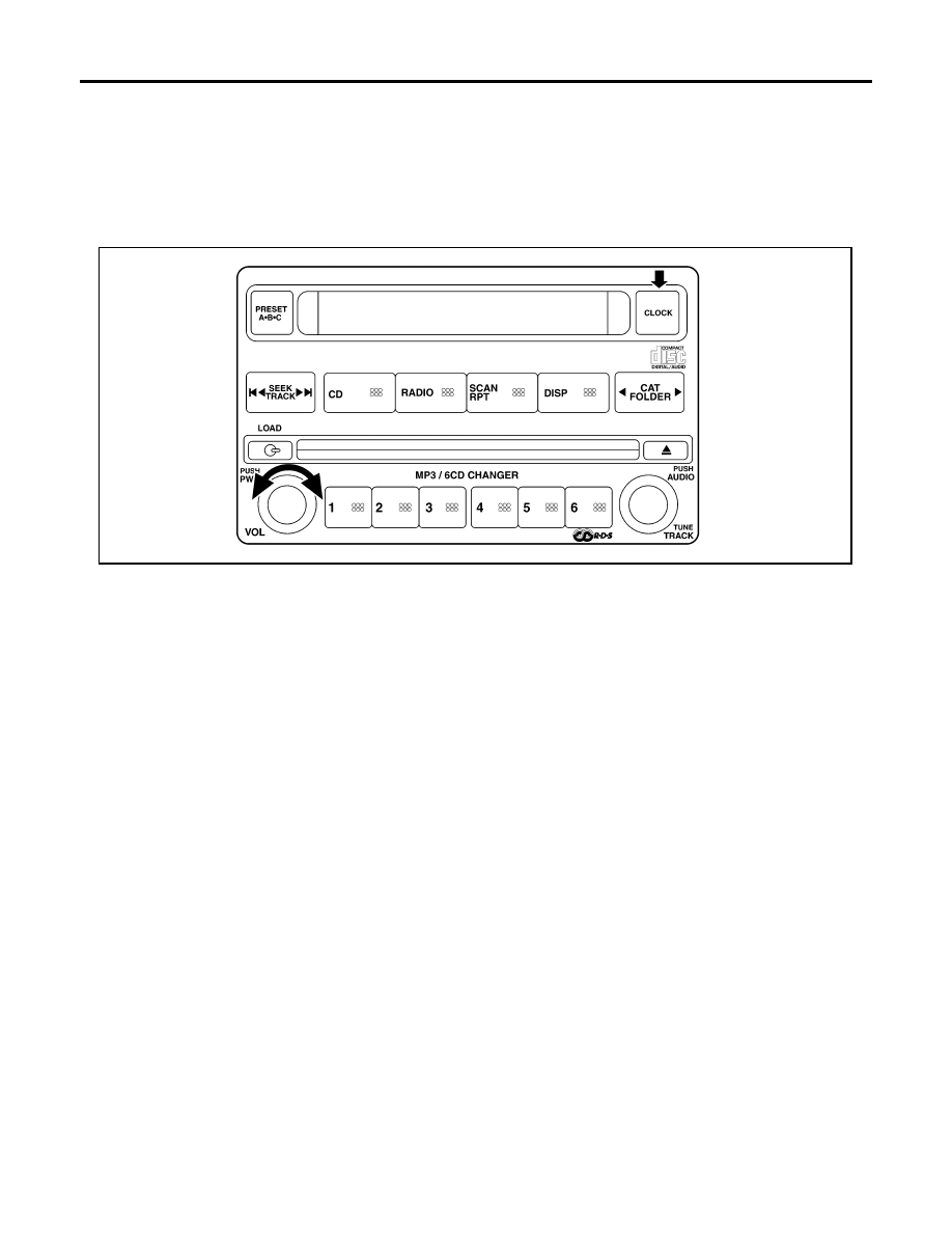
Audio Unit Self-Diagnosis Function (Premium System)
EKS00BZ8
It can check ON/OFF operation of each switch in the audio unit and diagnose the input signals from the steer-
ing switch.
STARTING THE SELF-DIAGNOSIS MODE
1.
Turn ignition switch from OFF to ACC.
2.
Press and hold the “CLOCK” switch and turn the volume control dial clockwise or counterclockwise for 30
clicks or more.
Then the self-diagnosis operates. A single beep indicates self-diagnosis mode is active.
3.
Initially, all display segments will be illuminated.
4.
Press each switch. When each switch is pressed, its name and communication code will be displayed.
NOTE:
CD player LOAD and EJECT buttons are not included in this test and will not change the display when
pressed.
EXITING THE SELF-DIAGNOSIS MODE
Turn ignition switch OFF. Then the self-diagnosis ends.
DIAGNOSIS FUNCTION
●
It can check for continuity of the switches by sounding a beep when each audio unit switch and steering
switch is pressed.
●
It can check for continuity of harness between audio unit and steering switch.
WKIA3368E

AUDIO
AV-29
C
D
E
F
G
H
I
J
L
M
A
B
AV
Revision: November 2005
2005 Frontier
Trouble Diagnosis
EKS00BZ9
The majority of the audio troubles are the result of outside causes (bad CD, electromagnetic interference,
etc.). Check the inspection items below to diagnose the malfunction.
MALFUNCTION WITH RADIO AND CD (BASE SYSTEM)
MALFUNCTION WITH RADIO AND CD [PREMIUM SYSTEM (KING CAB)]
MALFUNCTION WITH RADIO AND CD [PREMIUM SYSTEM (CREW CAB)]
Symptom
Possible cause
Inoperative
●
Audio unit power circuit check. Refer to
.
If above check is OK, replace audio unit.
All speakers do not sound
●
Audio unit
One or several speakers do not sound
●
Front door speaker check. Refer to
AV-35, "Sound Is Not Heard From Front
Door Speaker or Front Tweeter (Base System)"
●
Rear door speaker check. Refer to
AV-37, "Sound Is Not Heard From Rear
Poor sound
●
Audio unit
●
Speaker
Noisy
●
Audio unit
●
Electrical equipment (generator, bonding wire, etc.)
Symptom
Possible cause
Inoperative
●
Audio unit power circuit check. Refer to
.
If above check is OK, replace audio unit.
Steering switch does not operate
●
Steering switch check. Refer to
AV-32, "Steering Switch Check (Premium
If above check is OK, replace audio unit.
All speakers do not sound
●
Audio unit
One or several speakers do not sound
●
Front door speaker check. Refer to
AV-39, "Sound Is Not Heard From Front
Door Speaker or Front Tweeter [Premium System (King Cab)]"
●
Rear door speaker check. Refer to
AV-41, "Sound Is Not Heard From Rear
Door Speaker [Premium System (King Cab)]"
Poor sound
●
Audio unit
●
Speaker
Noisy
●
Audio unit
●
Electrical equipment (generator, bonding wire, etc.)
Symptom
Possible cause
Inoperative
●
Audio unit power circuit check. Refer to
If above check is OK, replace audio unit.
Steering switch does not operate
●
Steering switch check. Refer to
AV-32, "Steering Switch Check (Premium
If above check is OK, replace audio unit.
All speakers do not sound
●
Audio unit
●
Audio amplifier power supply and ground circuit check. Refer to
"Power Supply Circuit Inspection"
●
Audio amplifier ON signal
●
Audio amplifier

AV-30
AUDIO
Revision: November 2005
2005 Frontier
FOR RADIO ONLY
NOTE:
The following noise results from variations in field strength, such as fading noise and multi-path noise, or
external noise from trains and other sources. It is not a malfunction.
●
Fading noise: This noise occurs because of variations in the field strength in a narrow range due to moun-
tains or buildings blocking the signal.
●
Multi-path noise: This noise results from the waves sent directly from the broadcast station arriving at the
antenna at a different time from the waves which reflect off mountains or buildings.
FOR CD ONLY
Noise Inspection
EKS00BZA
The vehicle itself can be a source of noise if noise prevention parts or electrical equipment is malfunctioning.
Check if noise is caused and/or changed by engine speed, ignition switch turned to each position, and opera-
tion of each piece of electrical equipment, and determine the cause.
NOTE:
The source of the noise can be found easily by listening to the noise while removing the fuses of electrical
components, one by one.
One or several speakers do not sound
●
Front door speaker check. Refer to
AV-43, "Sound Is Not Heard From Front
Door Speaker or Front Tweeter [Premium System (Crew Cab)]"
●
Rear door speaker check. Refer to
AV-46, "Sound Is Not Heard From Rear
Door Speaker or Rear Door Tweeter [Premium System (Crew Cab)]"
.
●
AV-50, "Sound Is Not Heard From Subwoofer
.
Poor sound
●
Audio unit
●
Audio amplifier
●
Speaker
Noisy
●
Audio unit
●
Audio amplifier
●
Electrical equipment (generator, bonding wire, etc.)
Symptom
Possible cause
Symptom
Possible cause
No sound
●
Audio unit
●
Antenna feeder, wiring or connections
Noisy
●
Audio unit
●
Audio unit case ground
●
Antenna feeder, wiring or connections
●
Noise prevention parts
●
Electrical equipment
●
Wire harness of each piece of electrical equipment
All radio stations stored in memory are deleted
●
Audio unit power circuit. Refer to
●
Audio unit
Symptom
Possible cause
CD cannot be inserted.
●
CD
●
Audio unit
CD cannot be ejected.
The CD cannot be played.
The sound skips, stops suddenly, or is distorted.

AUDIO
AV-31
C
D
E
F
G
H
I
J
L
M
A
B
AV
Revision: November 2005
2005 Frontier
TYPE OF NOISE AND POSSIBLE CAUSE
Power Supply Circuit Inspection
EKS00BZB
1.
CHECK FUSES
Check that the following fuses are not blown.
OK or NG
OK
>> GO TO 2.
NG
>> If fuse is blown, be sure to eliminate cause of problem before installing new fuse. Refer to
"POWER SUPPLY ROUTING CIRCUIT"
Occurrence condition
Possible cause
Occurs only when engine is ON.
A continuous growling noise occurs. The speed of
the noise varies with changes in the engine speed.
●
Ignition components
A whistling noise occurs while the engine speed is
high. A booming noise occurs while the engine is
running and the lighting switch is ON.
●
Generator
The occurrence of the noise is linked with the operation of the fuel pump.
●
Fuel pump condenser
Noise only occurs when various
electrical components are oper-
ating.
A cracking or snapping sound occurs with the
operation of various switches.
●
Relay malfunction, audio unit malfunction
The noise occurs when various motors are operat-
ing.
●
Motor case ground
●
Motor
The noise occurs constantly, not just under certain conditions.
●
Rear defogger coil malfunction (crew cab)
●
Open circuit in printed heater (crew cab)
●
Poor ground of antenna feeder line
A cracking or snapping sound occurs while the vehicle is being driven, especially
when it is vibrating excessively.
●
Ground wire of body parts
●
Ground due to improper part installation
●
Wiring connections or a short circuit
Unit
Terminals
Signal name
Fuse No.
Audio unit
6
Battery power
29
10
Ignition switch ACC or ON
4
Audio amplifier
1
Battery power
17
17
AV-32
AUDIO
Revision: November 2005
2005 Frontier
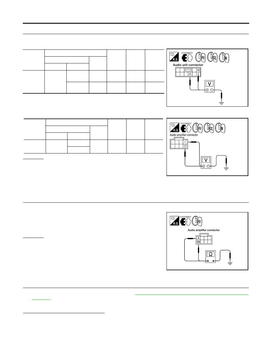
2.
POWER SUPPLY CIRCUIT CHECK
1.
Disconnect audio unit connector M43 and audio amplifier connector B158 [premium system (crew cab)].
2.
Check voltage between the audio unit and ground.
3.
Check voltage between audio amplifier [premium system (crew cab)] and ground.
OK or NG
OK
>>
●
Crew cab models with premium system, GO TO 3.
●
All other models, Inspection End.
NG
>>
●
Check connector housings for disconnected or loose
terminals.
●
Repair harness or connector.
3.
GROUND CIRCUIT CHECK
1.
Turn ignition switch OFF.
2.
Check continuity between audio amplifier harness connector
B158 terminal 4 and terminal 20 and ground.
OK or NG
OK
>> Inspection End.
NG
>>
●
Check connector housing for disconnected or loose
terminals.
●
Repair harness or connector.
Steering Switch Check (Premium System)
EKS00BZD
1.
SELF-DIAGNOSIS FUNCTION CHECK
1.
Start audio unit self-diagnosis function. Refer to
AV-28, "Audio Unit Self-Diagnosis Function (Premium
.
2.
Operate steering switch.
Does steering switch operate normally?
YES
>> Inspection End.
NO
>> GO TO 2.
Unit
Terminal No.
OFF
ACC
ON
(+)
(-)
Connector
Terminal
Audio unit
M43
6
Ground
Battery
voltage
Battery
voltage
Battery
voltage
10
Ground
0V
Battery
voltage
Battery
voltage
WKIA3228E
Unit
Terminal No.
OFF
ACC
ON
(+)
(-)
Connector
Terminal
Audio
amplifier
B158
1
Ground
Battery
voltage
Battery
voltage
Battery
voltage
17
WKIA3369E
Continuity should exist.
WKIA3370E
AUDIO
AV-33
C
D
E
F
G
H
I
J
L
M
A
B
AV
Revision: November 2005
2005 Frontier
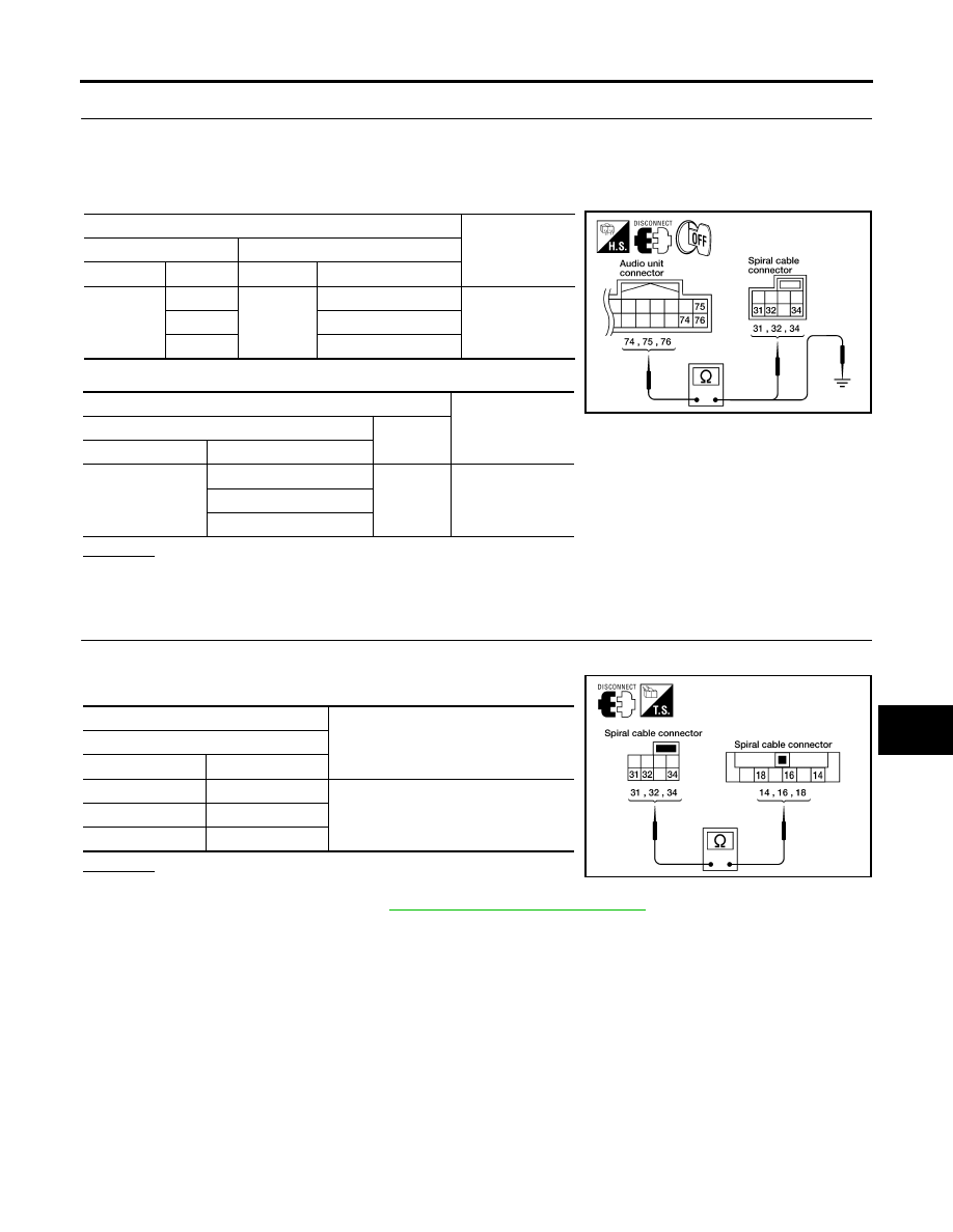
2.
CHECK HARNESS
1.
Turn ignition switch OFF.
2.
Disconnect audio unit connector M45 and spiral cable connector M30.
3.
Check continuity between spiral cable harness connector terminal and audio unit harness connector ter-
minal.
4.
Check continuity between audio unit and ground.
OK or NG
OK
>> GO TO 3.
NG
>> Repair harness.
3.
SPIRAL CABLE CHECK
1.
Disconnect spiral cable connectors M30 and M102.
2.
Check continuity between spiral cable terminals.
OK or NG
OK
>> GO TO 4.
NG
>> Replace spiral cable. Refer to
SRS-45, "Removal and Installation"
Terminals
Continuity
Spiral cable
Audio unit
Connector
Terminal
Connector
Terminal
M30
31
M45
75
Yes
32
76
34
74
Terminals
Continuity
Audio unit
—
Connector
Terminal
M45
74
Ground
No
75
76
WKIA3235E
Terminals
Continuity
Spiral cable
Terminal
Terminal
31
18
Yes
32
16
34
14
WKIA3233E
AV-34
AUDIO
Revision: November 2005
2005 Frontier
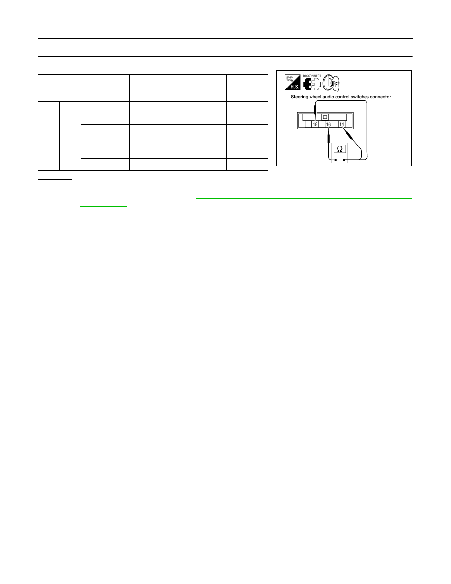
4.
CHECK STEERING SWITCH RESISTANCE
Check resistance between steering switch terminals.
OK or NG
OK
>> Inspection End.
NG
>> Replace steering switch. Refer to
AV-54, "Removal and Installation of Steering Wheel Audio Con-
Terminal
Signal name
Condition
Resistance
(
Ω
)
(Approx.)
18
16
Seek (down)
Depress (station) down switch.
165
Power
Depress power switch.
0
Volume (down)
Depress volume down switch.
652
14
16
Seek (up)
Depress (station) up switch.
165
Mode
Depress mode switch.
0
Volume (up)
Depress volume up switch.
652
WKIA3234E
AUDIO
AV-35
C
D
E
F
G
H
I
J
L
M
A
B
AV
Revision: November 2005
2005 Frontier
Sound Is Not Heard From Front Door Speaker or Front Tweeter (Base System)
EKS00BZG
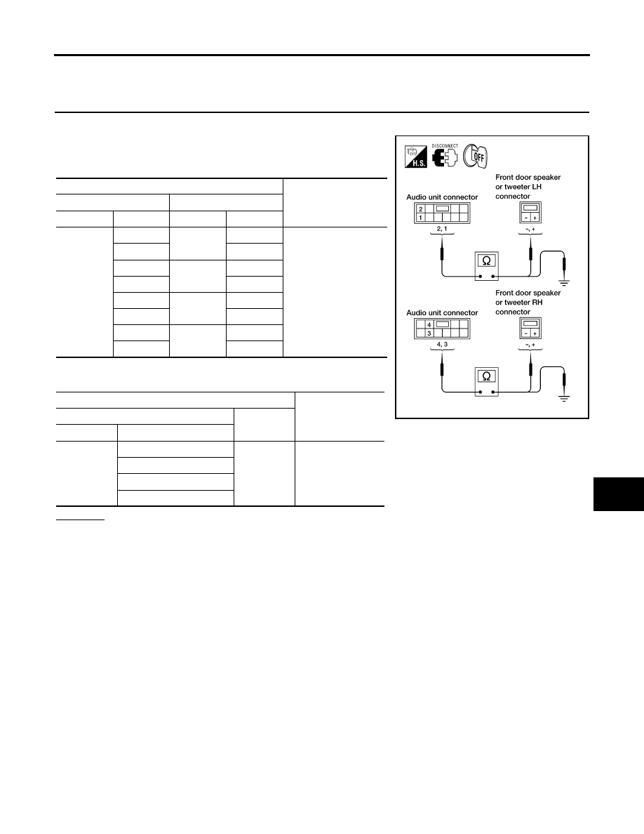
1.
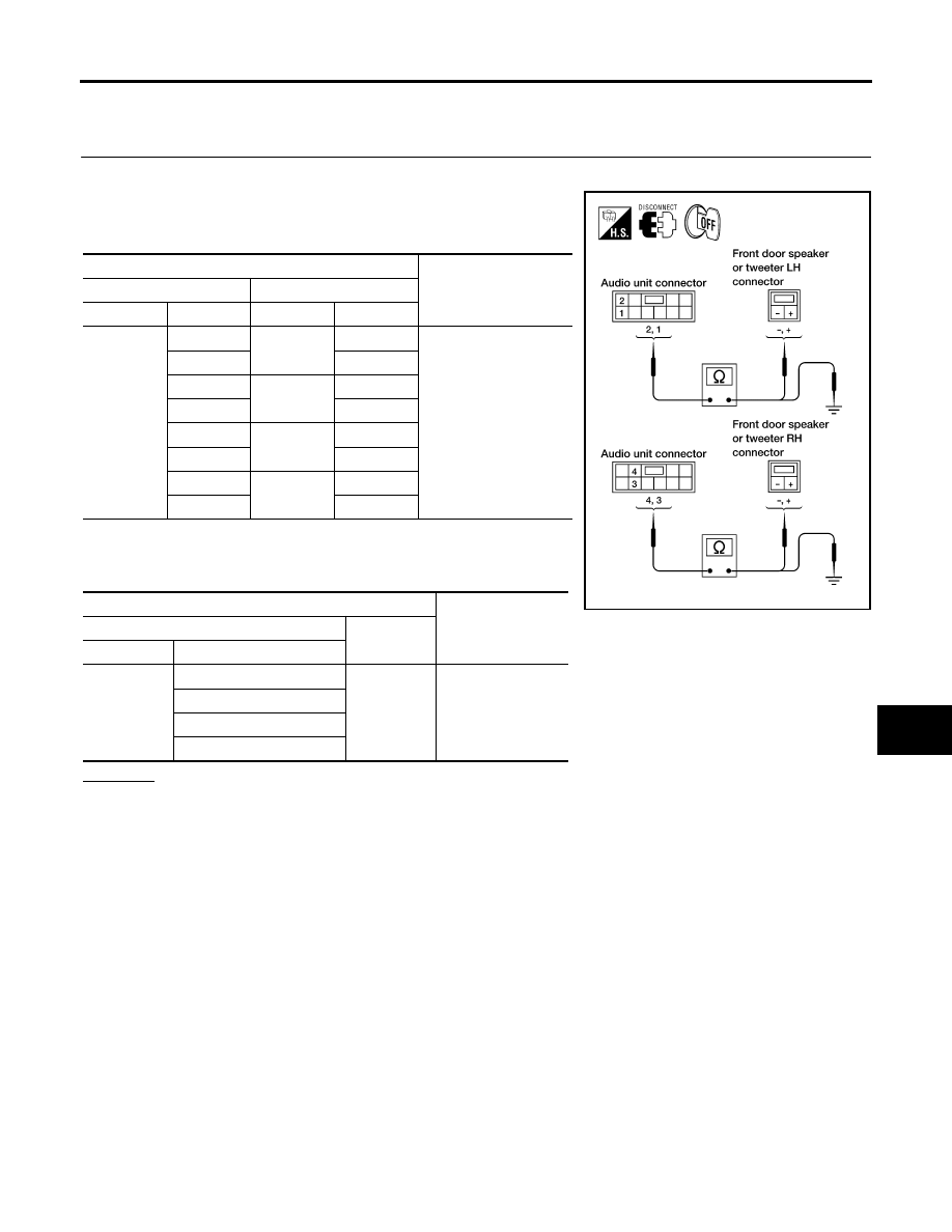
HARNESS CHECK
1.
Disconnect audio unit connector M43 and suspect speaker or tweeter (crew cab) connector.
2.
Check continuity between audio unit harness connector M43 ter-
minal and suspect speaker or tweeter (crew cab) harness con-
nector terminal.
*: Crew cab
3.
Check continuity between audio unit harness connector M43 ter-
minal and ground.
OK or NG
OK
>> GO TO 2.
NG
>>
●
Check connector housings for disconnected or loose terminals.
●
Repair harness or connector.
Terminals
Continuity
Audio unit
Speaker or tweeter
Connector
Terminal
Connector
Terminal
M43
2
D12
+
Yes
1
-
4
D112
+
3
-
2
M109*
+
1
-
4
M111*
+
3
-
Terminals
Continuity
Audio unit
—
Connector
Terminal
M43
2
Ground
No
1
4
3
WKIA1220E

AV-36
AUDIO
Revision: November 2005
2005 Frontier
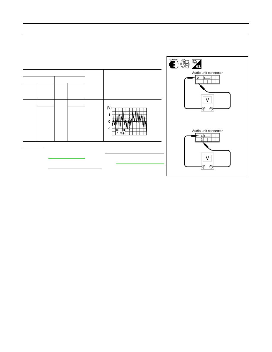
2.
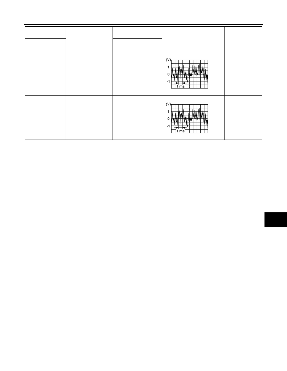
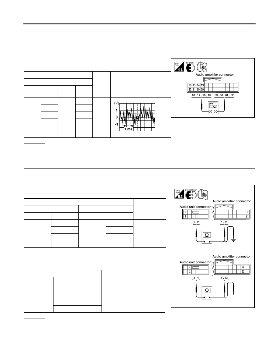
FRONT SPEAKER SIGNAL CHECK
1.
Connect audio unit connector and front speaker or tweeter (crew cab) connector.
2.
Turn ignition switch to ACC.
3.
Push “POWER” switch.
4.
Check the signal between audio unit harness connector terminal
and ground with CONSULT-II or oscilloscope.
OK or NG
OK
>> Replace speaker. Refer to
NG
>> Replace audio unit. Refer to
Terminals
Condi-
tion
Reference
signal
(+)
(-)
Con-
nec-
tor
Termi-
nal
Con-
nec-
tor
Termi-
nal
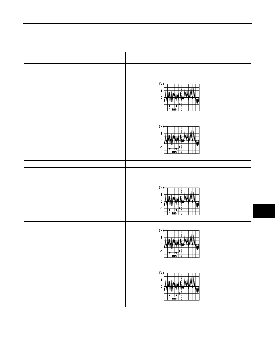
M43
2
M43
1
Receive
audio
signal
4
3
SKIA4278E
SKIA0177E
AUDIO
AV-37
C
D
E
F
G
H
I
J
L
M
A
B
AV
Revision: November 2005
2005 Frontier
Sound Is Not Heard From Rear Door Speaker (Base System)
EKS00BZH
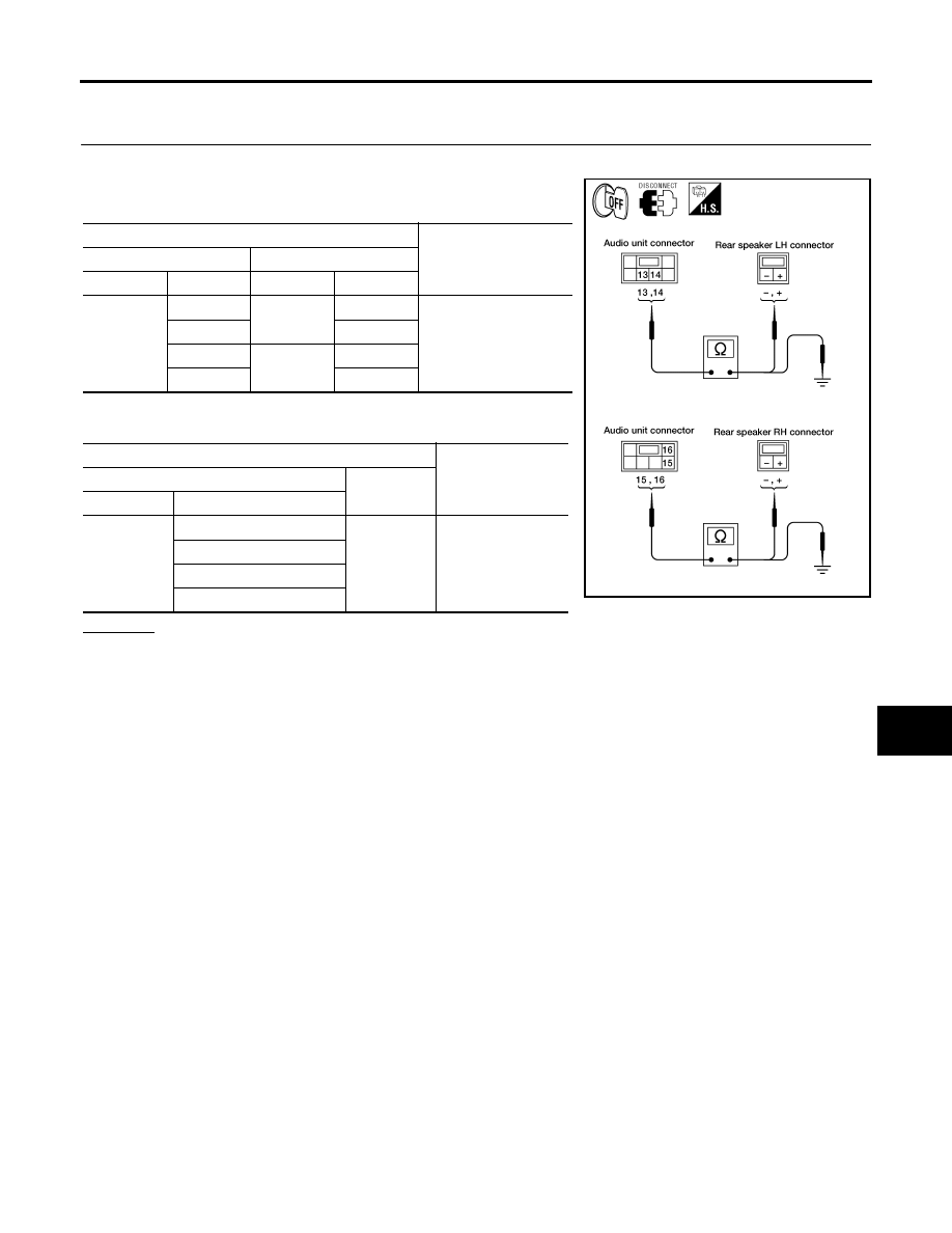
1.
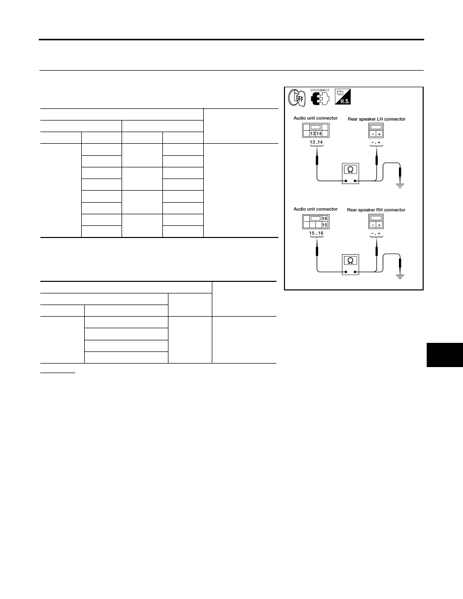
HARNESS CHECK
1.
Disconnect audio unit connector M44 and suspect speaker connector.
2.
Check continuity between audio unit harness connector M44 ter-
minal and suspect speaker harness connector terminal.
*1: King cab
*2: Crew cab
3.
Check continuity between audio unit harness connector M44 ter-
minal and ground.
OK or NG
OK
>> GO TO 2.
NG
>>
●
Check connector housings for disconnected or loose terminals.
●
Repair harness or connector.
Terminals
Continuity
Audio unit
Speaker or tweeter
Connector
Terminal
Connector
Terminal
M44
13
B76 *1
-
Yes
14
+
15
B160 *1
-
16
+
13
D207 *2
-
14
+
15
D307 *2
-
16
+
Terminals
Continuity
Audio unit
—
Connector
Terminal
M44
13
Ground
No
14
15
16
WKIA3371E
AV-38
AUDIO
Revision: November 2005
2005 Frontier
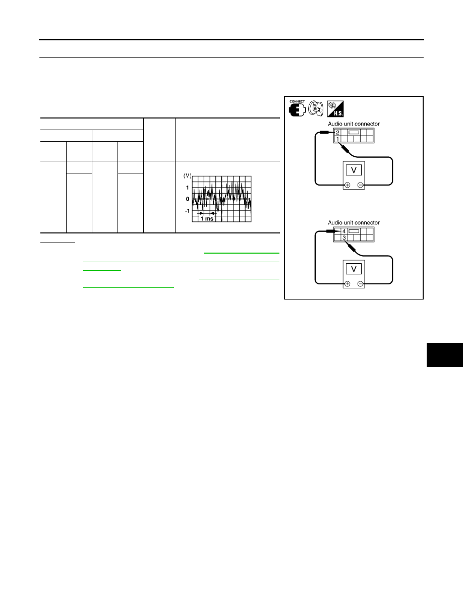
2.
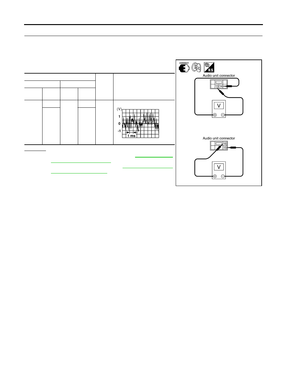
REAR SPEAKER SIGNAL CHECK
1.
Connect audio unit connector and rear speaker connector.
2.
Turn ignition switch to ACC.
3.
Push “POWER” switch.
4.
Check the signal between audio unit harness connector termi-
nals with CONSULT-II or oscilloscope.
OK or NG
OK
>> Replace rear door speaker. Refer to
.
NG
>> Replace audio unit. Refer to
Terminals
Condi-
tion
Reference
signal
(+)
(-)
Con-
nector
Termi-
nal
Con-
nector
Termi-
nal
M44
14
M44
13
Receiv
e audio
signal
16
15
SKIA4281E
SKIA0177E
AUDIO
AV-39
C
D
E
F
G
H
I
J
L
M
A
B
AV
Revision: November 2005
2005 Frontier
Sound Is Not Heard From Front Door Speaker or Front Tweeter [Premium Sys-
tem (King Cab)]
EKS00C2W
1.
HARNESS CHECK
1.
Disconnect audio unit connector M43 and suspect speaker or tweeter connector.
2.
Check continuity between audio unit harness connector M43 ter-
minal and suspect speaker or tweeter harness connector termi-
nal.
3.
Check continuity between audio unit harness connector M43 ter-
minal and ground.
OK or NG
OK
>> GO TO 2.
NG
>>
●
Check connector housings for disconnected or loose terminals.
●
Repair harness or connector.
Terminals
Continuity
Audio unit
Speaker or tweeter
Connector
Terminal
Connector
Terminal
M43
2
D12
+
Yes
1
-
4
D112
+
3
-
2
M109
+
1
-
4
M111
+
3
-
Terminals
Continuity
Audio unit
—
Connector
Terminal
M43
2
Ground
No
1
4
3
WKIA1220E
AV-40
AUDIO
Revision: November 2005
2005 Frontier
2.
FRONT SPEAKER SIGNAL CHECK
1.
Connect audio unit connector and front speaker or tweeter connector.
2.
Turn ignition switch to ACC.
3.
Push “POWER” switch.
4.
Check the signal between audio unit harness connector terminal
and ground with CONSULT-II or oscilloscope.
OK or NG
OK
>> Replace speaker. Refer to
NG
>> Replace audio unit. Refer to
Terminals
Condi-
tion
Reference
signal
(+)
(-)
Con-
nec-
tor
Termi-
nal
Con-
nec-
tor
Termi-
nal
M43
2
M43
1
Receive
audio
signal
4
3
SKIA4278E
SKIA0177E
AUDIO
AV-41
C
D
E
F
G
H
I
J
L
M
A
B
AV
Revision: November 2005
2005 Frontier
Sound Is Not Heard From Rear Door Speaker [Premium System (King Cab)]
EKS00C2X
1.
HARNESS CHECK
1.
Disconnect audio unit connector M44 and suspect speaker connector.
2.
Check continuity between audio unit harness connector M44 ter-
minal and suspect speaker harness connector terminal.
3.
Check continuity between audio unit harness connector M44 ter-
minal and ground.
OK or NG
OK
>> GO TO 2.
NG
>>
●
Check connector housings for disconnected or loose terminals.
●
Repair harness or connector.
Terminals
Continuity
Audio unit
Speaker or tweeter
Connector
Terminal
Connector
Terminal
M44
13
B76
-
Yes
14
+
15
B160
-
16
+
Terminals
Continuity
Audio unit
—
Connector
Terminal
M44
13
Ground
No
14
15
16
WKIA3371E

AV-42
AUDIO
Revision: November 2005
2005 Frontier
2.
REAR SPEAKER SIGNAL CHECK
1.
Connect audio unit connector and rear speaker connector.
2.
Turn ignition switch to ACC.
3.
Push “POWER” switch.
4.
Check the signal between audio unit harness connector termi-
nals with CONSULT-II or oscilloscope.
OK or NG
OK
>> Replace rear door speaker. Refer to
.
NG
>> Replace audio unit. Refer to
Terminals
Condi-
tion
Reference
signal
(+)
(-)
Con-
nector
Termi-
nal
Con-
nector
Termi-
nal
M44
14
M44
13
Receive
audio
signal
16
15
SKIA4281E
SKIA0177E
AUDIO
AV-43
C
D
E
F
G
H
I
J
L
M
A
B
AV
Revision: November 2005
2005 Frontier
Sound Is Not Heard From Front Door Speaker or Front Tweeter [Premium Sys-
tem (Crew Cab)]
EKS00BZI
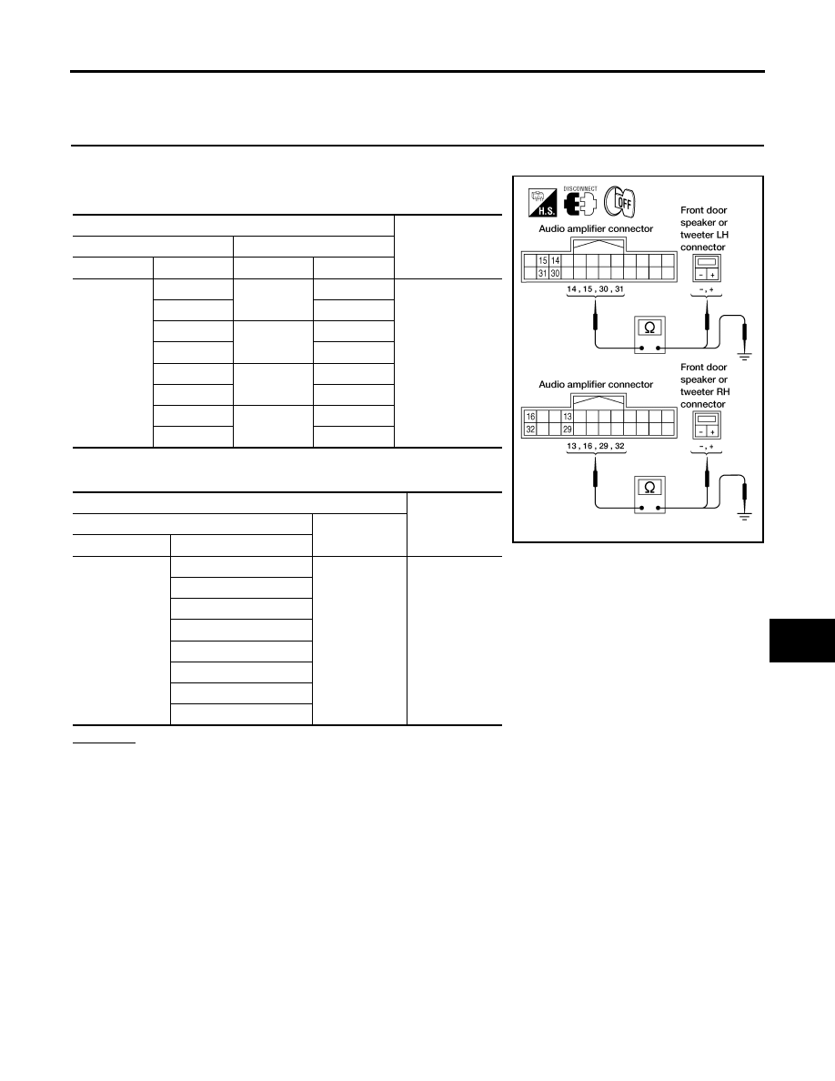
1.
HARNESS CHECK
1.
Disconnect audio amplifier connector B159 and suspect speaker connector.
2.
Check continuity between audio amplifier harness connector ter-
minal B159 and suspect speaker harness connector terminal.
3.
Check continuity between audio amplifier harness connector ter-
minal B159 and ground.
OK or NG
OK
>> GO TO 2.
NG
>>
●
Check connector housings for disconnected or loose terminals.
●
Repair harness or connector.
Terminals
Continuity
Audio amplifier
Speaker or tweeter
Connector
Terminal
Connector
Terminal
B159
15
D12
+
Yes
31
-
16
D112
+
32
-
14
M109
+
30
-
13
M111
+
29
-
Terminals
Continuity
Audio amplifier
—
Connector
Terminal
B159
13
Ground
No
14
15
16
29
30
31
32
WKIA3372E
AV-44
AUDIO
Revision: November 2005
2005 Frontier
2.
FRONT SPEAKER SIGNAL CHECK
1.
Connect audio amplifier connector B159 and suspect speaker connector.
2.
Turn ignition switch to ACC.
3.
Push “POWER” switch.
4.
Check the signal between audio amplifier harness connector
B159 terminals with CONSULT-II or oscilloscope.
OK or NG
OK
>> Replace suspect speaker. Refer to
AV-51, "Removal and Installation of Speaker"
NG
>> GO TO 3.
3.
HARNESS CHECK
1.
Turn ignition switch OFF.
2.
Disconnect audio unit connector M43 and audio amplifier connector B159.
3.
Check continuity between audio unit harness connector termi-
nals and audio amplifier harness connector terminals.
4.
Check continuity between audio unit harness connector termi-
nals and ground.
OK or NG
OK
>> GO TO 4.
NG
>>
●
Check connector housings for disconnected or loose terminals.
●
Repair harness or connector.
Terminals
Condi-
tion
Reference
signal
(+)
(-)
Con-
nector
Termi-
nal
Con-
nector
Termi-
nal
B159
13
B159
29
Receive
audio
signal
14
30
15
31
16
32
LKIA0602E
SKIA0177E
Terminals
Continuity
Audio unit
Audio amplifier
Connector
Terminal
Connector
Terminal
M43
1
B159
6
Yes
2
22
3
5
4
21
Terminals
Continuity
Audio unit
—
Connector
Terminal
M43
1
Ground
No
2
3
4
WKIA3374E
AUDIO
AV-45
C
D
E
F
G
H
I
J
L
M
A
B
AV
Revision: November 2005
2005 Frontier
4.
FRONT SPEAKER SIGNAL CHECK
1.
Connect audio unit connector and audio amplifier connector.
2.
Turn ignition switch to ACC.
3.
Push “POWER” switch.
4.
Check the signal between audio unit harness connector termi-
nals with CONSULT-II or oscilloscope.
OK or NG
OK
>> Replace audio amplifier. Refer to
Installation for Audio Amplifier (Premium System) -
Crew Cab"
.
NG
>> Replace audio unit. Refer to
.
Terminals
Condi-
tion
Reference
signal
(+)
(-)
Con-
nector
Termi-
nal
Con-
nector
Termi-
nal
M43
2
M43
1
Receive
audio
signal
4
3
SKIA4278E
SKIA0177E
AV-46
AUDIO
Revision: November 2005
2005 Frontier
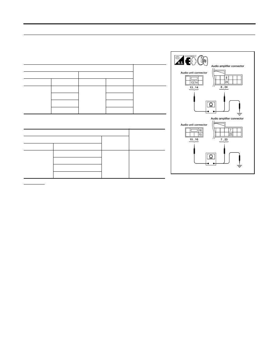
Sound Is Not Heard From Rear Door Speaker or Rear Door Tweeter [Premium
System (Crew Cab)]
EKS00BZJ
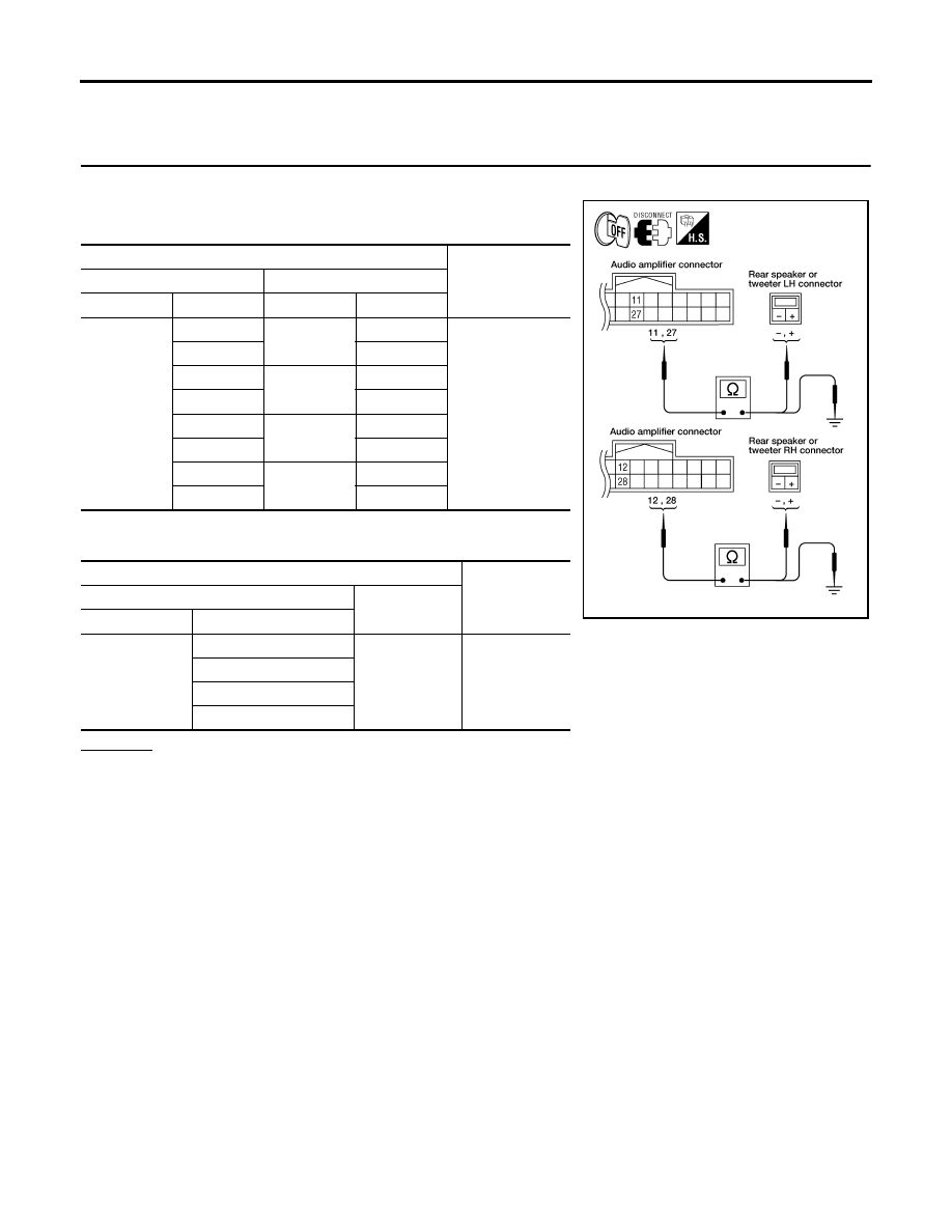
1.
HARNESS CHECK
1.
Disconnect audio amplifier connector B159 and suspect speaker connector.
2.
Check continuity between audio amplifier harness connector ter-
minal B159 and suspect speaker harness connector terminal.
3.
Check continuity between audio amplifier harness connector
B159 terminal and ground.
OK or NG
OK
>> GO TO 2.
NG
>>
●
Check connector housings for disconnected or loose terminals.
●
Repair harness or connector.
Terminals
Continuity
Audio amplifier
Speaker or tweeter
Connector
Terminal
Connector
Terminal
B159
11
D207
+
Yes
27
-
12
D307
+
28
-
11
D208
+
27
-
12
D308
+
28
-
Terminals
Continuity
Audio amplifier
—
Connector
Terminal
B159
11
Ground
No
27
12
28
WKIA3375E
AUDIO
AV-47
C
D
E
F
G
H
I
J
L
M
A
B
AV
Revision: November 2005
2005 Frontier
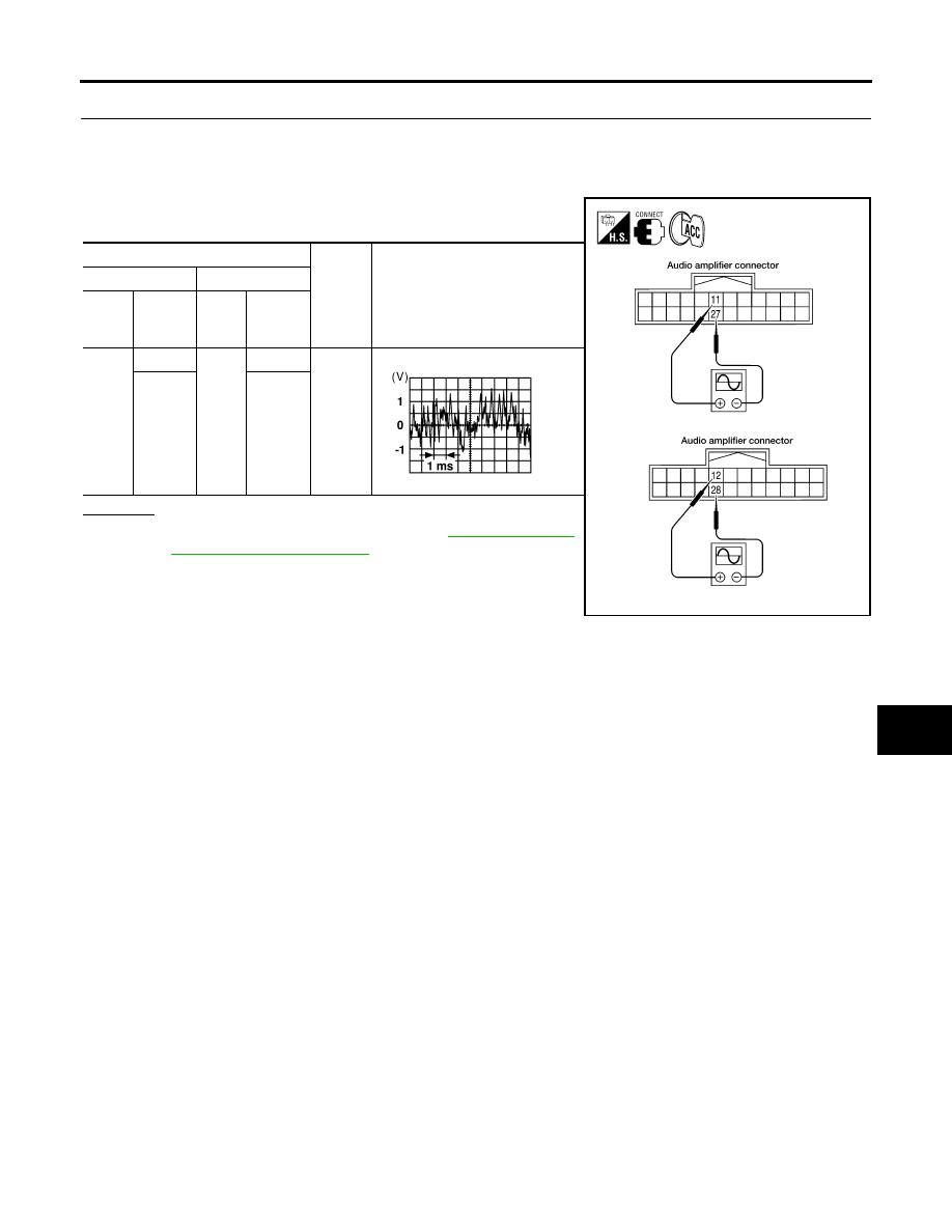
2.
REAR SPEAKER SIGNAL CHECK
1.
Connect audio amplifier connector B159 and suspect speaker connector.
2.
Turn ignition switch to ACC.
3.
Push “POWER” switch.
4.
Check the signal between audio amplifier harness connector
B159 terminals with CONSULT-II or oscilloscope.
OK or NG
OK
>> Replace suspect speaker. Refer to
NG
>> GO TO 3.
Terminals
Condi-
tion
Reference
signal
(+)
(-)
Con-
nec-
tor
Terminal
Con-
nec-
tor
Terminal
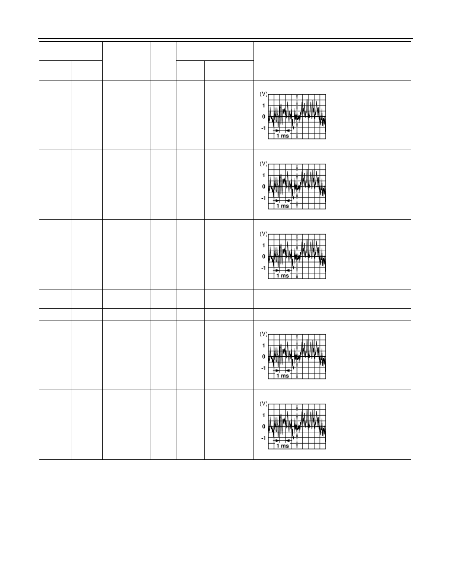
B159
11
B159
27
Receive
audio
signal
12
28
WKIA3376E
SKIA0177E
AV-48
AUDIO
Revision: November 2005
2005 Frontier
3.
HARNESS CHECK
1.
Turn ignition switch OFF.
2.
Disconnect audio unit connector M44 and audio amplifier connector B159.
3.
Check continuity between audio unit harness connector M44 ter-
minals and audio amplifier harness connector B159 terminals.
4.
Check continuity between audio unit harness connector terminal
and ground.
OK or NG
OK
>> GO TO 4.
NG
>>
●
Check connector housings for disconnected or loose terminals.
●
Repair harness or connector.
Terminals
Continuity
Audio unit
Audio amplifier
Connector
Terminal
Connector
Terminal
M44
13
B159
8
Yes
14
24
15
7
16
23
Terminals
Continuity
Audio unit
—
Connector
Terminal
M44
13
Ground
No
14
15
16
WKIA3377E
AUDIO
AV-49
C
D
E
F
G
H
I
J
L
M
A
B
AV
Revision: November 2005
2005 Frontier
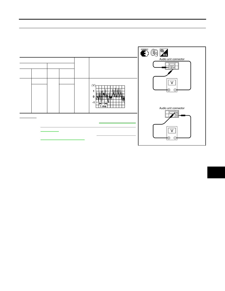
4.
REAR SPEAKER SIGNAL CHECK
1.
Connect audio unit connector M44 and audio amplifier connector B159.
2.
Turn ignition switch to ACC.
3.
Push “POWER” switch.
4.
Check the signal between audio unit harness connector M44
terminals with CONSULT-II or oscilloscope.
OK or NG
OK
>> Replace audio amplifier. Refer to
Installation for Audio Amplifier (Premium System) -
Crew Cab"
.
NG
>> Replace audio unit. Refer to
.
Terminals
Condi-
tion
Reference
signal
(+)
(-)
Con-
nector
Terminal
Con-
nector
Terminal
M44
14
M44
13
Receive
audio
signal
16
15
SKIA4316E
SKIA0177E
AV-50
AUDIO
Revision: November 2005
2005 Frontier
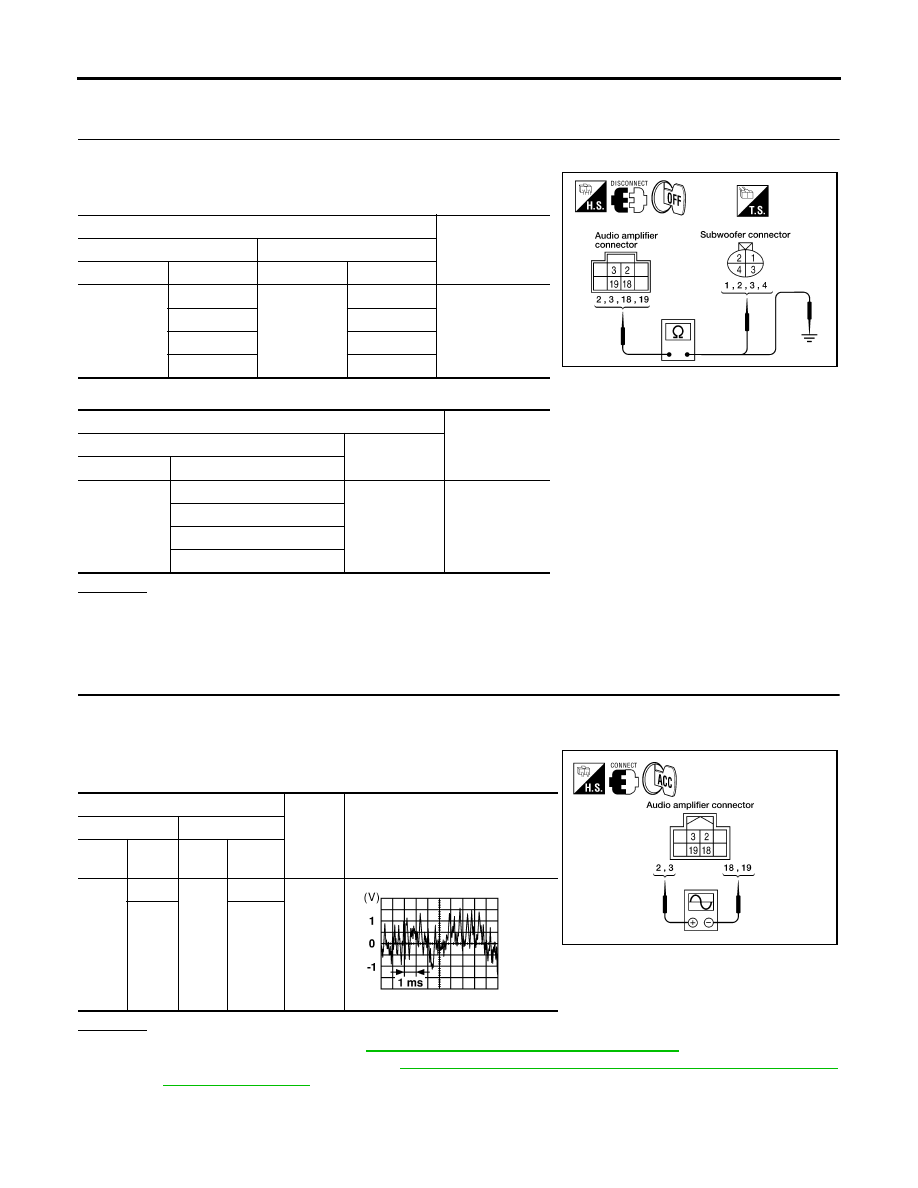
Sound Is Not Heard From Subwoofer [Premium System (Crew Cab)]
EKS00BZK
1.
HARNESS CHECK
1.
Disconnect audio amplifier connector B158 and subwoofer connector B72.
2.
Check continuity between audio amplifier harness connector ter-
minal and subwoofer harness connector terminal.
3.
Check continuity between audio amplifier harness connector terminal and ground.
OK or NG
OK
>> GO TO 2.
NG
>>
●
Check connector housings for disconnected or loose terminals.
●
Repair harness or connector.
2.
SUBWOOFER SIGNAL CHECK
1.
Connect audio amplifier connector and subwoofer connector.
2.
Turn ignition switch to ACC.
3.
Check the signal between audio amplifier harness connector ter-
minals with CONSULT-II or oscilloscope.
OK or NG
OK
>> Replace subwoofer. Refer to
AV-51, "Removal and Installation of Speaker"
NG
>> Replace audio amplifier. Refer to
AV-53, "Removal and Installation for Audio Amplifier (Premium
Terminals
Continuity
Audio amplifier
Subwoofer
Connector
Terminal
Connector
Terminal
B158
2
B72
1
Yes
3
3
18
2
19
4
Terminals
Continuity
Audio amplifier
—
Connector
Terminal
B158
2
Ground
No
3
18
19
WKIA3378E
Terminals
Condi-
tion
Reference
signal
(+)
(-)
Con-
nector
Termi-
nal
Con-
nector
Termi-
nal
B158
2
B158
18
Receive
audio
signal
3
19
WKIA3379E
SKIA0177E
AUDIO
AV-51
C
D
E
F
G
H
I
J
L
M
A
B
AV
Revision: November 2005
2005 Frontier
Removal and Installation for Audio Unit
EKS00BZL
REMOVAL
1.
Disconnect the negative battery cable.
2.
Using power tool, remove the audio unit screws.
3.
Remove cluster lid C. Refer to
4.
Pull out audio unit and disconnect connectors.
INSTALLATION
Installation is in the reverse order of removal.
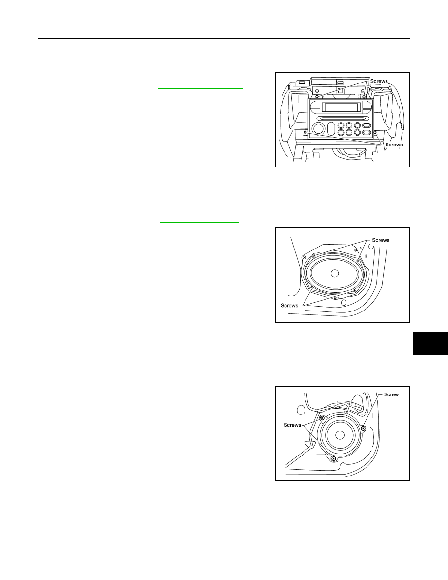
Removal and Installation of Speaker
EKS00BZN
REMOVAL - FRONT DOOR SPEAKER
1.
Remove door finisher. Refer to
2.
Remove the front door speaker screws.
3.
Disconnect the connector and remove speaker from front door.
INSTALLATION - FRONT DOOR SPEAKER
Installation is in the reverse order of removal.
REMOVAL - REAR DOOR SPEAKER
1.
Remove the rear door finisher. Refer to
2.
Remove the rear door speaker screws.
3.
Disconnect the connector and remove speaker from rear door.
INSTALLATION - REAR DOOR SPEAKER
Installation is in the reverse order of removal.
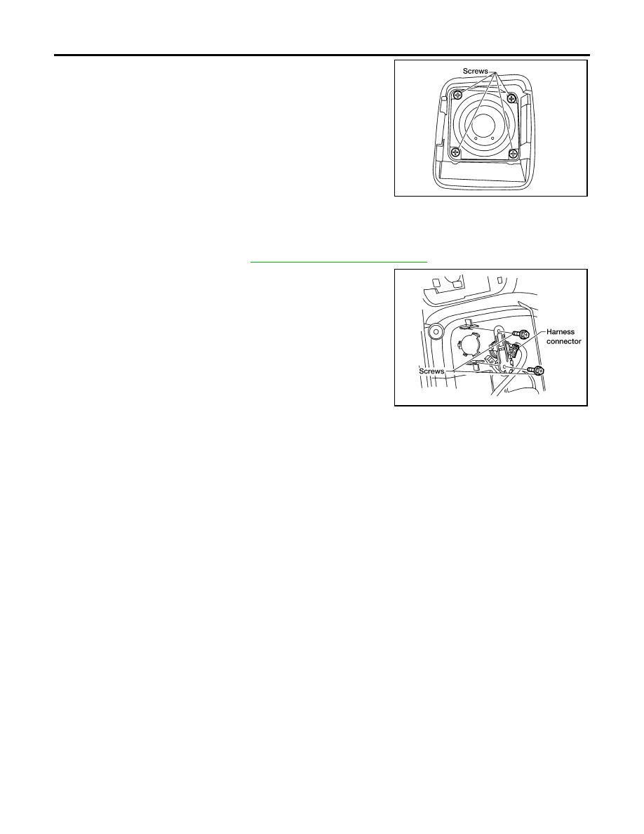
REMOVAL - FRONT TWEETER
1.
Remove the front tweeter grille.
LKIA0582E
WKIA1498E
Front door speaker screws
: 3.5 N·m (0.36 kg-m, 31 in-lb)
WKIA1492E
Rear door speaker screws
: 3.5 N·m (0.36 kg-m, 31 in-lb)
AV-52
AUDIO
Revision: November 2005
2005 Frontier
2.
Remove the front tweeter screws.
3.
Disconnect the connector, and remove front tweeter from instru-
ment panel.
INSTALLATION - FRONT TWEETER
Installation is in the reverse order of removal.
REMOVAL - REAR DOOR TWEETER - CREW CAB
1.
Remove rear door finisher. Refer to
2.
Remove the rear door tweeter screws.
3.
Remove rear door tweeter from rear door finisher.
INSTALLATION - REAR DOOR TWEETER - CREW CAB
Installation is in the reverse order of removal.
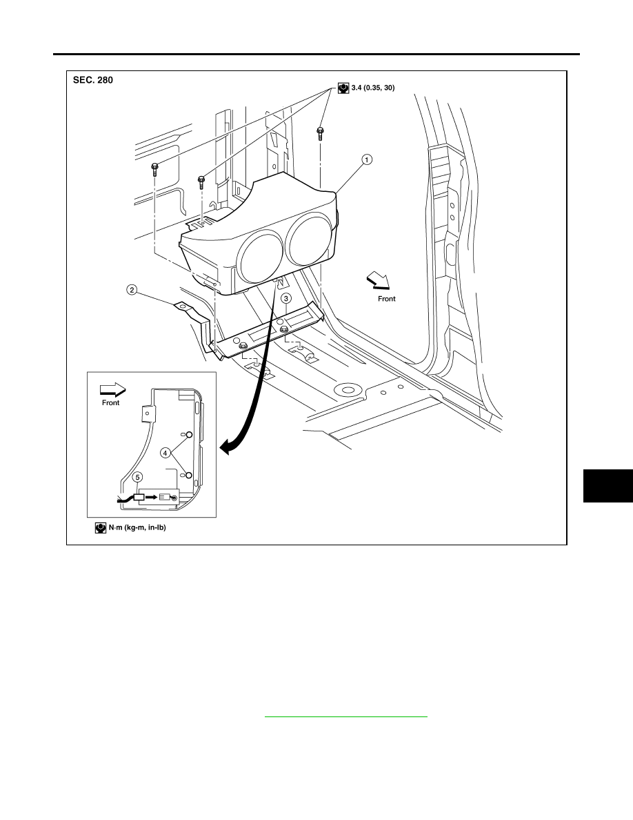
REMOVAL - SUBWOOFER (PREMIUM SYSTEM) - CREW CAB
1.
Position the LH rear seat cushion in the folded up position.
2.
Remove the subwoofer screws.
WKIA3735E
LKIA0586E
Rear door tweeter screws
: 3.5 N·m (0.36 kg-m, 31 in-lb)
AUDIO
AV-53
C
D
E
F
G
H
I
J
L
M
A
B
AV
Revision: November 2005
2005 Frontier
3.
Disconnect the connector and remove the subwoofer.
INSTALLATION - SUBWOOFER (PREMIUM SYSTEM) - CREW CAB
Installation is in the reverse order of removal.
NOTE:
Locate subwoofer assembly over alignment pins prior to installing subwoofer screws.
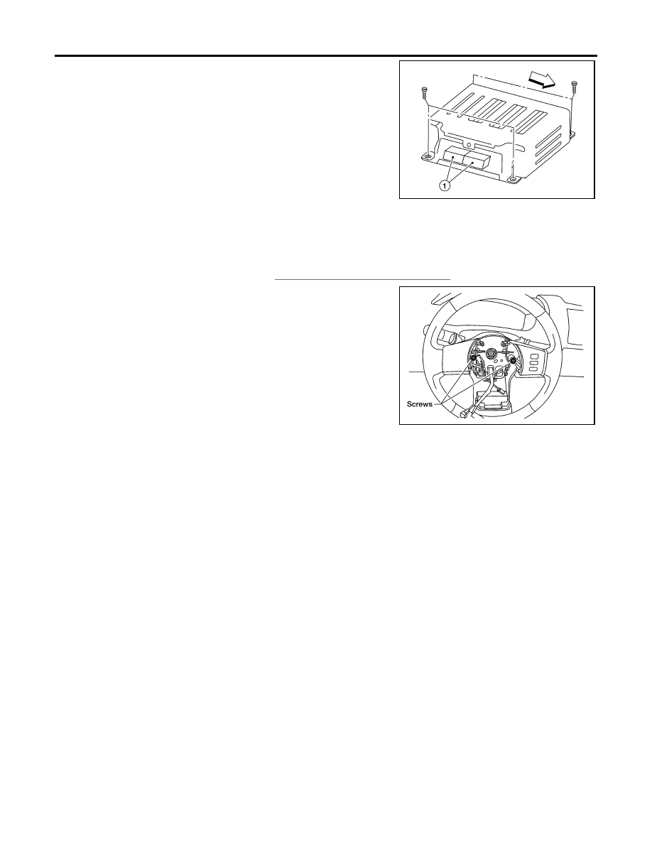
Removal and Installation for Audio Amplifier (Premium System) - Crew Cab
EKS00D8H
REMOVAL
1.
Disconnect the negative battery cable.
2.
Remove front passenger seat. Refer to
SE-19, "Removal and Installation"
3.
Using power tool, remove kick shield screws.
LKIA0639E
1.
Subwoofer
2.
Bracket
3.
Locating pin plate
4.
Locating pin
5.
Connector
AV-54
AUDIO
Revision: November 2005
2005 Frontier
4.
Disconnect connectors (1) and remove audio amplifier from kick
shield.
INSTALLATION
Installation is in the reverse order of removal.
Removal and Installation of Steering Wheel Audio Control Switches
EKS00BZO
REMOVAL
1.
Remove driver air bag module. Refer to
SRS-43, "Removal and Installation"
.
2.
Remove steering wheel audio control switch assembly screws.
3.
Disconnect the switch connector, and remove from steering
wheel.
INSTALLATION
Installation is in the reverse order of removal.
LKIA0661E
LKIA0589E
AUDIO ANTENNA
AV-55
C
D
E
F
G
H
I
J
L
M
A
B
AV
Revision: November 2005
2005 Frontier
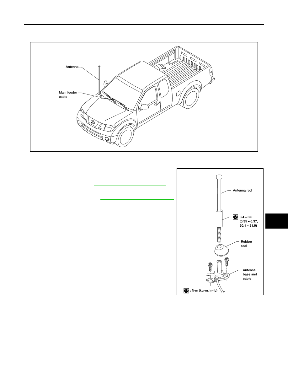
AUDIO ANTENNA
PFP:28200
Location of Antenna
EKS00D6P
Fixed Antenna Rod Replacement
EKS00D6Q
REMOVAL
1.
Remove antenna rod.
2.
Remove rubber seal.
3.
Remove cowl top. Refer to
EI-20, "Removal and Installation"
.
4.
Remove antenna base bolts.
5.
Remove audio unit. Refer to
AV-51, "Removal and Installation
.
6.
Disconnect antenna cable from audio unit.
7.
Remove antenna base and cable.
INSTALLATION
Install in reverse order of removal.
CAUTION:
Always properly tighten the antenna rod during installation or the antenna rod may bend or break dur-
ing vehicle operation.
LKIA0612E
AEL610C

AV-56
AUDIO ANTENNA
Revision: November 2005
2005 Frontier
Document Outline
- QUICK REFERENCE INDEX
- Table of Contents
- PRECAUTIONS
- PREPARATION
- AUDIO
- Component Parts and Harness Connector Location
- System Description
- Schematic
- Wiring Diagram — AUDIO —
- Terminals and Reference Value for Audio Unit (Base System)
- Terminals and Reference Value for Audio Unit [Premium System (King Cab)]
- Terminals and Reference Value for Audio Unit [Premium System (Crew Cab)]
- Terminals and Reference Value for Audio Amplifier [Premium System (Crew Cab)]
- Audio Unit Self-Diagnosis Function (Premium System)
- Trouble Diagnosis
- Noise Inspection
- Power Supply Circuit Inspection
- Steering Switch Check (Premium System)
- Sound Is Not Heard From Front Door Speaker or Front Tweeter (Base System)
- Sound Is Not Heard From Rear Door Speaker (Base System)
- Sound Is Not Heard From Front Door Speaker or Front Tweeter [Premium System (King Cab)]
- Sound Is Not Heard From Rear Door Speaker [Premium System (King Cab)]
- Sound Is Not Heard From Front Door Speaker or Front Tweeter [Premium System (Crew Cab)]
- Sound Is Not Heard From Rear Door Speaker or Rear Door Tweeter [Premium System (Crew Cab)]
- Sound Is Not Heard From Subwoofer [Premium System (Crew Cab)]
- Removal and Installation for Audio Unit
- Removal and Installation of Speaker
- REMOVAL - FRONT DOOR SPEAKER
- INSTALLATION - FRONT DOOR SPEAKER
- REMOVAL - REAR DOOR SPEAKER
- INSTALLATION - REAR DOOR SPEAKER
- REMOVAL - FRONT TWEETER
- INSTALLATION - FRONT TWEETER
- REMOVAL - REAR DOOR TWEETER - CREW CAB
- INSTALLATION - REAR DOOR TWEETER - CREW CAB
- REMOVAL - SUBWOOFER (PREMIUM SYSTEM) - CREW CAB
- INSTALLATION - SUBWOOFER (PREMIUM SYSTEM) - CREW CAB
- Removal and Installation for Audio Amplifier (Premium System) - Crew Cab
- Removal and Installation of Steering Wheel Audio Control Switches
- AUDIO ANTENNA
- POWER SUPPLY ROUTING CIRCUIT
- ELECTRICAL UNITS
- SUPER MULTIPLE JUNCTION (SMJ)
- FUSE BLOCK-JUNCTION BOX (J/B)
- FUSE AND FUSIBLE LINK BOX
- FUSE AND RELAY BOX
Wyszukiwarka
Podobne podstrony:
Danilo StaMta y Pasto DR PastoMagistrados(120309) DR(AV)
ROZŁAM-Odnowa, AV dokumentalny, Różne, Mszały, ministrantura
23 Fortell om situasjonen? oljen truet hele sørøstkysten av USA
67 AV System
AIWA AV S17
bajkal 95, AV dokumentalny, Syberia
Harman Kardon Amplituner AV AVR171
AV
blokowy av id 57628 Nieznany
AV
av
Sprawa śpiewów, AV dokumentalny, Różne, Mszały, ministrantura
Syberia w oczach polskich zesłańców, AV dokumentalny, Syberia
Hakerzy NET AV
polaczenia AV
CB y DG Mllin, Rionegro, La?ja? Corporacion Region V2 AT (AV)
Warunki mieszkaniowe Polaków deportowanych do ZSRR 1940-1946, AV dokumentalny, Syberia
2008 anleitung anlage av
więcej podobnych podstron