
AV
AV-1
DRIVER INFORMATION & MULTIMEDIA
C
D
E
F
G
H
I
J
K
L
M
B
SECTION
AV
A
O
P
CONTENTS
AUDIO, VISUAL & NAVIGATION SYSTEM
AUDIO LESS
PRECAUTION ...............................................
PRECAUTIONS ...................................................
PREPARATION ............................................
PREPARATION ...................................................
Commercial Service Tools ........................................
REMOVAL AND INSTALLATION ................
ANTENNA BASE ................................................
Exploded View ..........................................................
Removal and Installation ...........................................
ANTENNA FEEDER ............................................
Harness Layout .........................................................
AUDIO SYSTEM
BASIC INSPECTION ....................................
DIAGNOSIS AND REPAIR WORKFLOW ..........
Work Flow .................................................................
SYSTEM DESCRIPTION .............................
AUDIO SYSTEM .................................................
System Diagram ......................................................
System Description .................................................
Component Parts Location ......................................
Component Description ...........................................
HANDS-FREE PHONE SYSTEM .......................
System Diagram ......................................................
System Description .................................................
Component Parts Location ......................................
Component Description ...........................................
DIAGNOSIS SYSTEM (AUDIO UNIT) ..............
MODELS WITH iPod® CONNECTION FUNC-
TION : Diagnosis Description ..................................
MODELS WITHOUT iPod® CONNECTION
FUNCTION : Diagnosis Description ........................
DIAGNOSIS SYSTEM (TEL ADAPTER UNIT) ...
Diagnosis Description ..............................................
DTC/CIRCUIT DIAGNOSIS .........................
POWER SUPPLY AND GROUND CIRCUIT ....
AUDIO UNIT ...............................................................
AUDIO UNIT : Diagnosis Procedure .......................
IPOD ADAPTER ........................................................
iPod ADAPTER : Diagnosis Procedure ...................
SATELLITE RADIO TUNER ......................................
TEL ADAPTER UNIT .................................................
TEL ADAPTER UNIT : Diagnosis Procedure ..........
STEERING SWITCH SIGNAL A CIRCUIT
(STEERING SWITCH TO AUDIO UNIT) ...........
Description ...............................................................
Diagnosis Procedure ...............................................
Component Inspection .............................................
STEERING SWITCH SIGNAL B CIRCUIT
(STEERING SWITCH TO AUDIO UNIT) ...........
Description ...............................................................
Diagnosis Procedure ...............................................
Component Inspection .............................................
Revision: 2009 March
2009 Z12

AV-2
STEERING SWITCH SIGNAL GND CIRCUIT
(STEERING SWITCH TO AUDIO UNIT) ...........
Description ..............................................................
Diagnosis Procedure ..............................................
Component Inspection ............................................
STEERING SWITCH SIGNAL A CIRCUIT
(AUDIO UNIT TO TEL ADAPTER UNIT) ..........
Description ..............................................................
Diagnosis Procedure ..............................................
STEERING SWITCH SIGNAL B CIRCUIT
(AUDIO UNIT TO TEL ADAPTER UNIT) ..........
Description ..............................................................
Diagnosis Procedure ..............................................
STEERING SWITCH SIGNAL GND CIRCUIT
(AUDIO UNIT TO TEL ADAPTER UNIT) ..........
Description ..............................................................
Diagnosis Procedure ..............................................
COMMUNICATION SIGNAL CIRCUIT ..............
Description ..............................................................
Diagnosis Procedure ..............................................
Description ..............................................................
Diagnosis Procedure ..............................................
WOOFER AMP. ON SIGNAL CIRCUIT .............
Description ..............................................................
Diagnosis Procedure ..............................................
MICROPHONE SIGNAL CIRCUIT ....................
Description ..............................................................
Diagnosis Procedure ..............................................
TELEPHONE ON SIGNAL CIRCUIT .................
Description ..............................................................
Diagnosis Procedure ..............................................
ECU DIAGNOSIS INFORMATION ..............
AUDIO UNIT ......................................................
Reference Value .....................................................
Wiring Diagram - AUDIO - ......................................
WOOFER ...........................................................
Reference Value .....................................................
Wiring Diagram - AUDIO - ......................................
SATELLITE RADIO TUNER ..............................
Reference Value .....................................................
Wiring Diagram - AUDIO - ......................................
TEL ADAPTER UNIT .........................................
Reference Value .....................................................
Wiring Diagram - AUDIO - ......................................
iPod ADAPTER ...............................................
Reference Value ....................................................
Wiring Diagram - AUDIO - ....................................
SYMPTOM DIAGNOSIS ...........................
AUDIO SYSTEM SYMPTOMS .........................
Symptom Table .....................................................
HANDS-FREE PHONE SYMPTOMS ...............
Symptom Table .....................................................
NORMAL OPERATING CONDITION ...............
Description ............................................................
PRECAUTION ...........................................
PRECAUTIONS ................................................
PREPARATION .........................................
PREPARATION ................................................
Commercial Service Tools ....................................
REMOVAL AND INSTALLATION .............
AUDIO UNIT .....................................................
Exploded View ......................................................
Removal and Installation .......................................
FRONT DOOR SPEAKER ................................
Exploded View ......................................................
Removal and Installation .......................................
TWEETER .........................................................
Exploded View ......................................................
Removal and Installation .......................................
REAR DOOR SPEAKER ..................................
Exploded View ......................................................
Removal and Installation .......................................
WOOFER ..........................................................
Exploded View ......................................................
Removal and Installation .......................................
ANTENNA BASE ..............................................
MODELS WITH SATELLITE RADIO SYSTEM .......
MODELS WITHOUT SATELLITE RADIO SYSTEM
.
MODELS WITHOUT SATELLITE RADIO SYS-
TEM : Exploded View ............................................
MODELS WITHOUT SATELLITE RADIO SYS-
TEM : Removal and Installation ............................
SATELLITE RADIO TUNER .............................
Revision: 2009 March
2009 Z12

AV
AV-3
C
D
E
F
G
H
I
J
K
L
M
B
A
O
P
Exploded View ......................................................
Removal and Installation .......................................
TEL ADAPTER UNIT .......................................
Exploded View ......................................................
Removal and Installation .......................................
MICROPHONE .................................................
Exploded View ......................................................
Removal and Installation .......................................
iPod ADAPTER ................................................
Exploded View ......................................................
Removal and Installation .......................................
iPod CONNECTOR .........................................
Exploded View .......................................................
Removal and Installation .......................................
ANTENNA FEEDER ........................................
MODELS WITH SATELLITE RADIO SYSTEM .......
MODELS WITHOUT SATELLITE RADIO SYSTEM
..
MODELS WITHOUT SATELLITE RADIO SYS-
TEM : Harness Layout ...........................................
Revision: 2009 March
2009 Z12

AV-4
< PRECAUTION >
[AUDIO LESS]
PRECAUTIONS
PRECAUTION
PRECAUTIONS
Precaution for Supplemental Restraint System (SRS) "AIR BAG" and "SEAT BELT
PRE-TENSIONER"
INFOID:0000000005158179
The Supplemental Restraint System such as “AIR BAG” and “SEAT BELT PRE-TENSIONER”, used along
with a front seat belt, helps to reduce the risk or severity of injury to the driver and front passenger for certain
types of collision. This system includes seat belt switch inputs and dual stage front air bag modules. The SRS
system uses the seat belt switches to determine the front air bag deployment, and may only deploy one front
air bag, depending on the severity of a collision and whether the front occupants are belted or unbelted.
Information necessary to service the system safely is included in the “SRS AIR BAG” and “SEAT BELT” of this
Service Manual.
WARNING:
• To avoid rendering the SRS inoperative, which could increase the risk of personal injury or death in
the event of a collision which would result in air bag inflation, all maintenance must be performed by
an authorized NISSAN/INFINITI dealer.
• Improper maintenance, including incorrect removal and installation of the SRS, can lead to personal
injury caused by unintentional activation of the system. For removal of Spiral Cable and Air Bag
Module, see the “SRS AIR BAG”.
• Do not use electrical test equipment on any circuit related to the SRS unless instructed to in this
Service Manual. SRS wiring harnesses can be identified by yellow and/or orange harnesses or har-
ness connectors.
PRECAUTIONS WHEN USING POWER TOOLS (AIR OR ELECTRIC) AND HAMMERS
WARNING:
• When working near the Air Bag Diagnosis Sensor Unit or other Air Bag System sensors with the
ignition ON or engine running, DO NOT use air or electric power tools or strike near the sensor(s)
with a hammer. Heavy vibration could activate the sensor(s) and deploy the air bag(s), possibly
causing serious injury.
• When using air or electric power tools or hammers, always switch the ignition OFF, disconnect the
battery, and wait at least 3 minutes before performing any service.
Revision: 2009 March
2009 Z12

AV
PREPARATION
AV-5
< PREPARATION >
[AUDIO LESS]
C
D
E
F
G
H
I
J
K
L
M
B
A
O
P
PREPARATION
PREPARATION
Commercial Service Tools
INFOID:0000000004983596
Tool name
Description
Power tool
Loosening bolts and nuts
PBIC0191E
Revision: 2009 March
2009 Z12
AV-6
< REMOVAL AND INSTALLATION >
[AUDIO LESS]
ANTENNA BASE
REMOVAL AND INSTALLATION
ANTENNA BASE
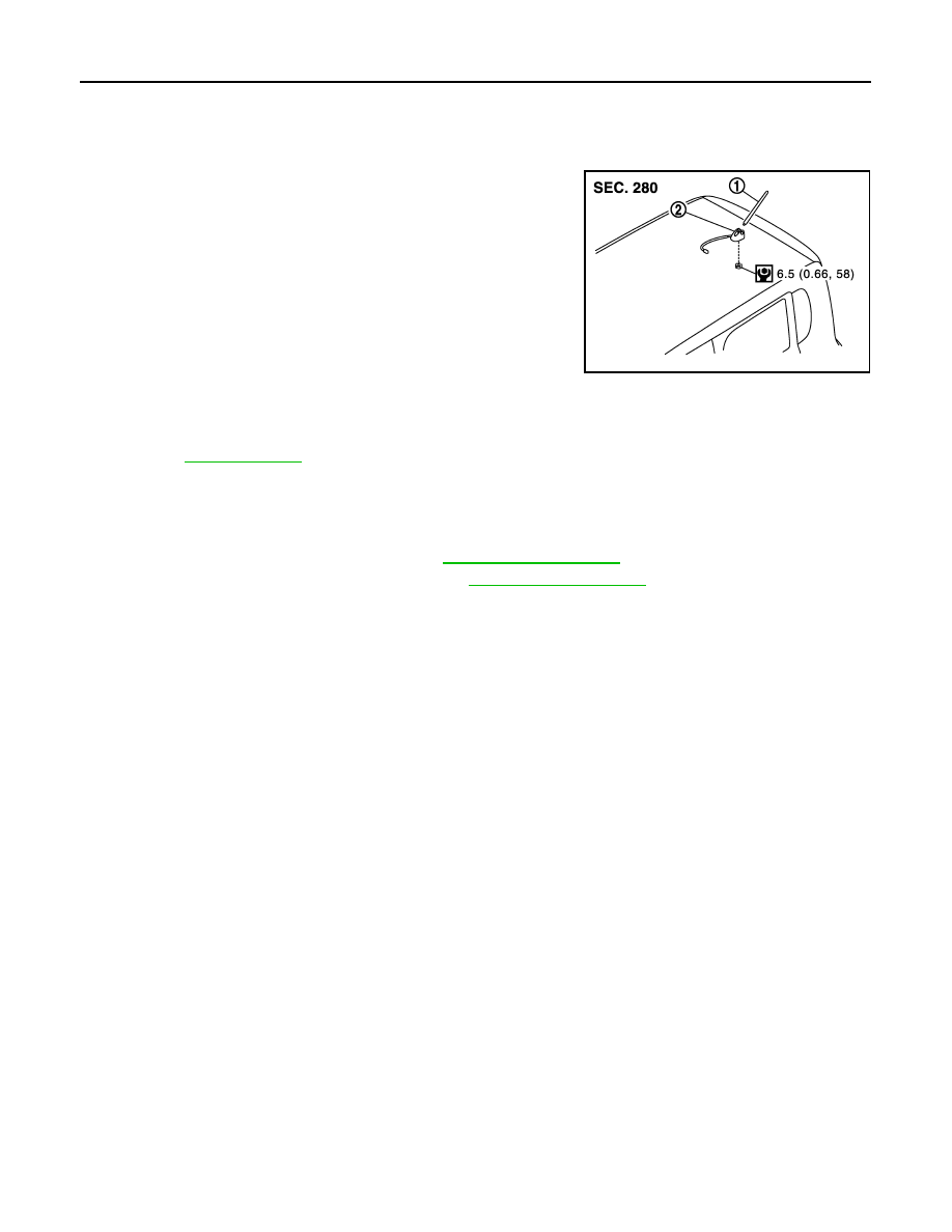
Exploded View
INFOID:0000000005087551
Removal and Installation
INFOID:0000000005087552
REMOVAL
1.
Remove luggage side upper finisher. Refer to
2.
Remove assist grip and headlining clips. Refer to
.
3.
Pull headlining (rear). Obtain a service area.
4.
Remove antenna base mounting nut.
5.
Remove antenna base.
INSTALLATION
Install in the reverse order of removal.
CAUTION:
Be careful about tightening torque. Antenna sensitivity becomes poor, and when it is excessive, roof
panel may be deformed, when antenna base mounting nut tightening torque is loose.
JSNIA1962GB
1.
Antenna rod
2.
Antenna base
for symbols in the figure.
Revision: 2009 March
2009 Z12
AV
ANTENNA FEEDER
AV-7
< REMOVAL AND INSTALLATION >
[AUDIO LESS]
C
D
E
F
G
H
I
J
K
L
M
B
A
O
P
ANTENNA FEEDER
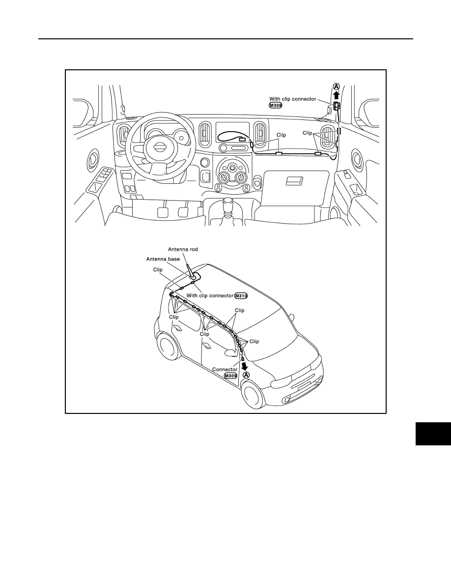
Harness Layout
INFOID:0000000004983615
JPNIA1722GB
Revision: 2009 March
2009 Z12
AV-8
< BASIC INSPECTION >
[AUDIO SYSTEM]
DIAGNOSIS AND REPAIR WORKFLOW
BASIC INSPECTION
DIAGNOSIS AND REPAIR WORKFLOW
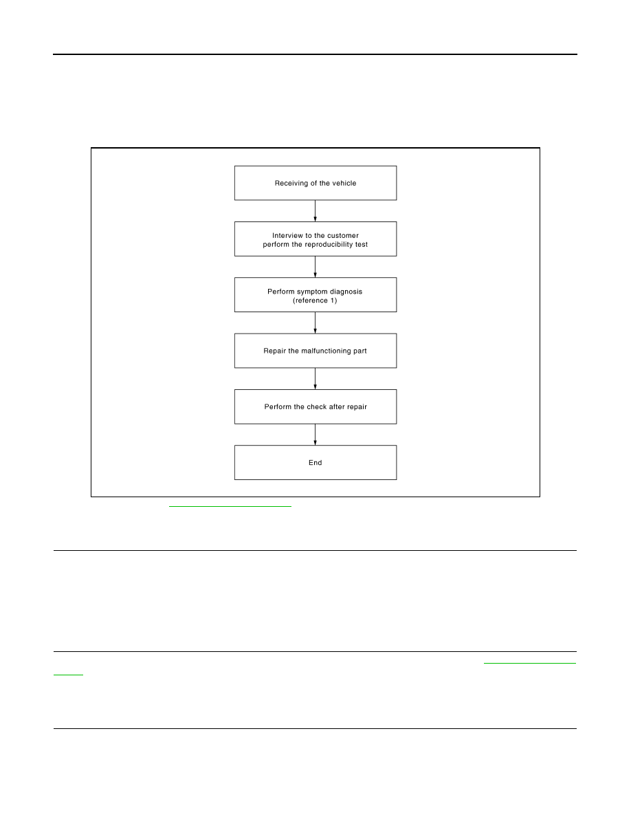
Work Flow
INFOID:0000000004940210
OVERALL SEQUENCE
Reference 1 ··· Refer to
.
DETAILED FLOW
1.
CHECK SYMPTOM
Check the malfunction symptoms by performing the following items.
• Interview the customer to obtain the malfunction information (conditions and environment when the malfunc-
tion occurred).
• Check the symptom.
>> GO TO 2.
2.
PERFORM DIAGNOSIS BY SYMPTOM
Perform the relevant diagnosis referring to the diagnosis chart by symptom. Refer to
.
>> GO TO 3.
3.
REPAIR OR REPLACE MALFUNCTIONING PARTS
Repair or replace the malfunctioning parts.
>> GO TO 4.
JSNIA0669GB
Revision: 2009 March
2009 Z12

AV
DIAGNOSIS AND REPAIR WORKFLOW
AV-9
< BASIC INSPECTION >
[AUDIO SYSTEM]
C
D
E
F
G
H
I
J
K
L
M
B
A
O
P
4.
FINAL CHECK
Perform the operation to check that the malfunction symptom is solved or any other symptoms are present.
Is there any symptom?
YES
>> GO TO 2.
NO
>> INSPECTION END
Revision: 2009 March
2009 Z12
AV-10
< SYSTEM DESCRIPTION >
[AUDIO SYSTEM]
AUDIO SYSTEM
SYSTEM DESCRIPTION
AUDIO SYSTEM
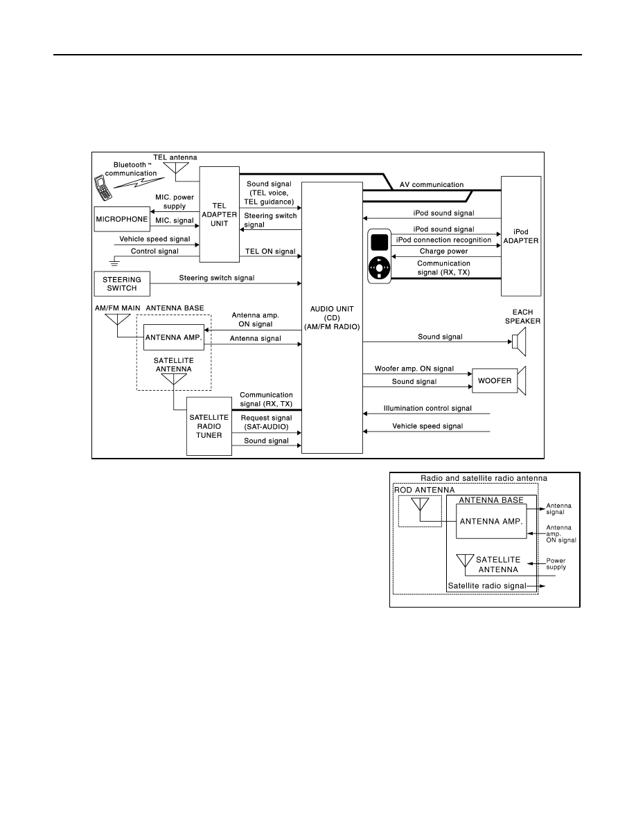
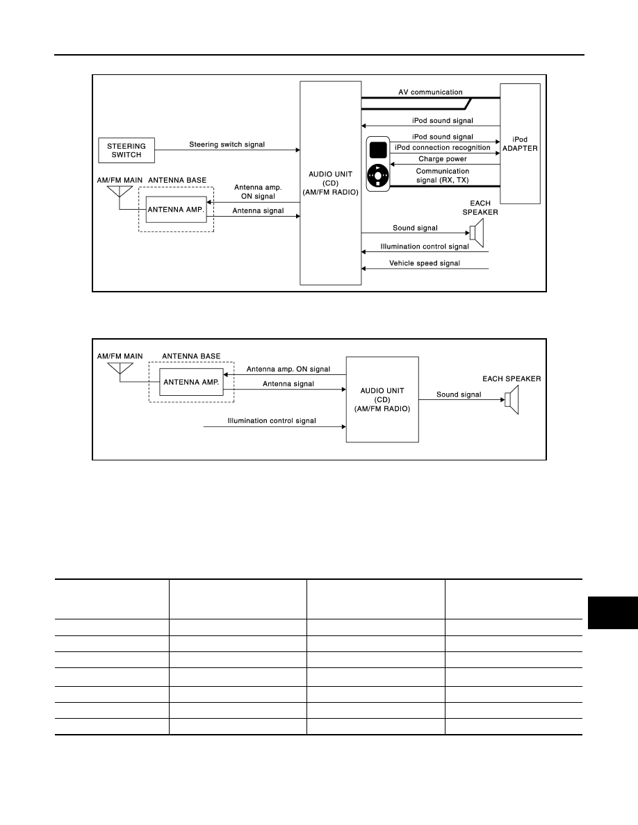
System Diagram
INFOID:0000000004940211
MODELS WITH iPod
®
CONNECTION FUNCTION AND HANDS-FREE PHONE SYSTEM
NOTE:
An antenna base integrated with radio antenna amp. and satellite
radio antenna is adopted.
JPNIA1642GB
JSNIA1062GB
Revision: 2009 March
2009 Z12
AV
AUDIO SYSTEM
AV-11
< SYSTEM DESCRIPTION >
[AUDIO SYSTEM]
C
D
E
F
G
H
I
J
K
L
M
B
A
O
P
MODELS WITH iPod
®
CONNECTION FUNCTION
NOTE:
An antenna base integrated with radio antenna amp. is adopted.
MODELS WITHOUT iPod
®
CONNECTION FUNCTION
NOTE:
An antenna base integrated with radio antenna amp. is adopted.
iPod
®
is a trademark of Apple inc., registered in the U.S. and other countries.
System Description
INFOID:0000000004940212
AUDIO SYSTEM
Audio functions
×
: Applicable
iPod
®
is a trademark of Apple inc., registered in the U.S. and other countries.
When the audio system is on, radio signals are received by the radio antenna. The audio unit then sends
audio signals to the each speaker.
FUNCTION DESCRIPTION
JPNIA1781GB
JPNIA1643GB
Models without iPod
®
connection
function
Models with iPod
®
connection
function
Models with iPod
®
connection
function and hands-free phone
system
AM/FM radio
×
×
×
CD
×
×
×
AUX connection
×
×
×
iPod
®
connection
—
×
×
Speed sensitive volume
—
×
×
Satellite radio
—
—
×
Hands-free phone system
—
—
×
Revision: 2009 March
2009 Z12

AV-12
< SYSTEM DESCRIPTION >
[AUDIO SYSTEM]
AUDIO SYSTEM
AM/FM Radio Mode
• AM/FM radio tuner is built into audio unit.
• Radio signals are received by radio antenna, next they are amplified by antenna amp., and finally the they
are input to audio unit. (Antenna amp. is built into antenna base.)
• Audio unit outputs the sound signal to each speaker. (models without woofer)
• Audio unit outputs the sound signal to woofer and each speaker. (models with woofer)
Satellite Radio System
• Radio signals are supplied to satellite radio tuner from the satellite radio antenna. (satellite radio antenna is
built into antenna base.)
• The satellite radio tuner sends sound signal to the audio unit.
• Audio unit outputs the sound signal to each speaker. (models without woofer)
• Audio unit outputs the sound signal to woofer and each speaker. (models with woofer)
iPod
®
Connection
• Connect iPod
®
and iPod adapter with wire harness and iPod adapter input iPod sound signal from iPod
®
.
• When iPod mode is selected, iPod adapter outputs iPod sound signal to audio unit.
• Audio unit outputs the sound signal to each speaker. (models without woofer)
• Audio unit outputs the sound signal to woofer and each speaker. (models with woofer)
AUX Connection
• When the external device is connected to the AUX (auxiliary) input jack of the audio unit, the external device
inputs a sound signal to the audio unit.
• When AUX mode is selected, audio unit outputs sound signal to each speaker. (models without woofer)
• When AUX mode is selected, audio unit outputs sound signal to woofer and each speaker. (models with
woofer)
Speed Sensitive Volume
• Volume level of this system gone up and down automatically in proportion to the vehicle speed.
• The control level can be selected by the customer.
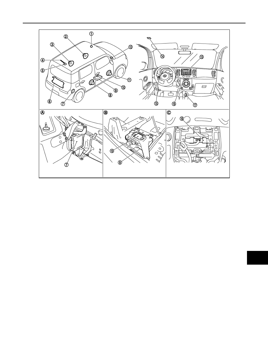
Component Parts Location
INFOID:0000000004940213
MODELS WITH iPod
®
CONNECTION FUNCTION
Revision: 2009 March
2009 Z12
AV
AUDIO SYSTEM
AV-13
< SYSTEM DESCRIPTION >
[AUDIO SYSTEM]
C
D
E
F
G
H
I
J
K
L
M
B
A
O
P
MODELS WITHOUT iPod
®
CONNECTION FUNCTION
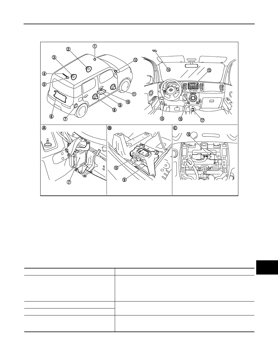
1.
Tweeter LH
2.
Front door speaker LH
3.
Rear door speaker LH
4.
Antenna rod
5.
Antenna base (antenna amp. and
satellite antenna)
6.
Woofer
7.
Satellite radio tuner
8.
Rear door speaker RH
9.
TEL adapter unit
10. TEL antenna
11. Front door speaker RH
12. Tweeter RH
13. Audio unit
14. Microphone
15. Steering switch
16. iPod adapter
17. iPod connector
A.
Luggage side RH
B.
Floor spacer is removed condition.
C.
A/C finisher is removed condition.
JPNIA1721ZZ
Revision: 2009 March
2009 Z12
AV-14
< SYSTEM DESCRIPTION >
[AUDIO SYSTEM]
AUDIO SYSTEM
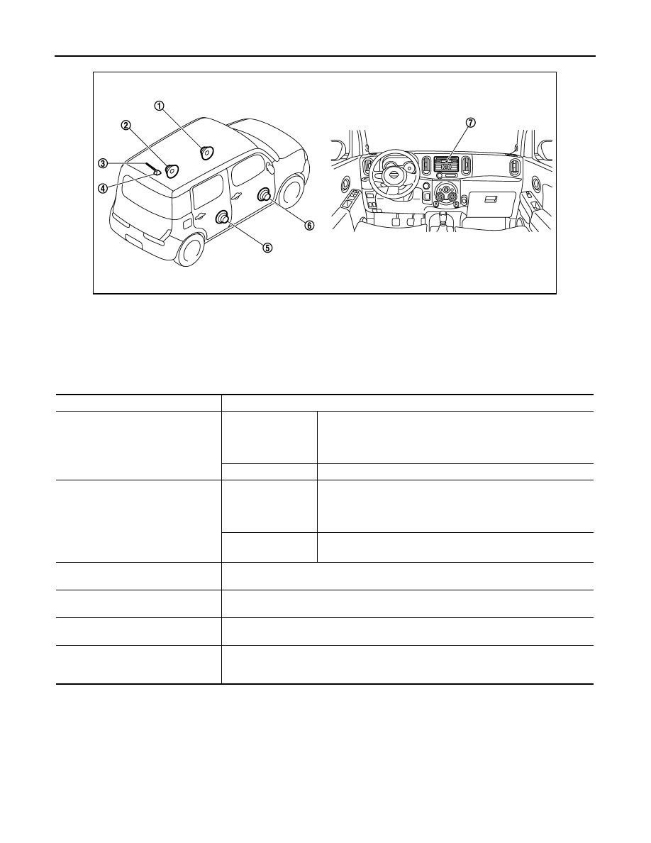
Component Description
INFOID:0000000004940214
1.
Front door speaker LH
2.
Rear door speaker LH
3.
Antenna rod
4.
Antenna base (antenna amp.)
5.
Rear door speaker RH
6.
Front door speaker RH
7.
Audio unit
JPNIA1720ZZ
Part name
Description
Audio unit
Models with iPod
®
connection function
and hands-free
phone system
Controls audio system, satellite radio system, and hands-free phone
system functions.
Except for above.
Controls audio system function.
Steering switch
Models with iPod
®
connection function
and hands-free
phone system
• Operation for audio and hands-free phone are possible.
• Steering switch signal (operation signal) is output to audio unit.
• Steering switch signal (operation signal) is output to TEL adapter
unit through audio unit.
Models with iPod
®
connection function
• Operation for audio is possible.
• Steering switch signal (operation signal) is output to audio unit.
Front door speaker
• Outputs sound signal from audio unit.
• Outputs high, mid and low range sounds.
Tweeter
• Outputs sound signal from audio unit.
• Outputs high range sounds.
Rear door speaker
• Outputs sound signal from audio unit.
• Outputs high, mid and low range sounds.
Woofer
• Woofer amp. ON signal is input from audio unit.
• Outputs sound signal from audio unit.
• Outputs low frequency sound.
Revision: 2009 March
2009 Z12

AV
AUDIO SYSTEM
AV-15
< SYSTEM DESCRIPTION >
[AUDIO SYSTEM]
C
D
E
F
G
H
I
J
K
L
M
B
A
O
P
iPod
®
is a trademark of Apple inc., registered in the U.S. and other countries.
Antenna base
Models with iPod
®
connection function
and hands-free
phone system
An antenna base integrated with antenna amp. and satellite radio
antenna is adopted.
Antenna amp.
• Radio signal received by rod antenna is amplified and transmitted
to audio unit.
• Power (antenna amp. ON signal) is supplied from audio unit.
Satellite radio antenna
• Receives the satellite radio wave and outputs it to the satellite ra-
dio tuner.
Except for above.
• An antenna base integrated with antenna amp.
• Radio signal received by rod antenna is amplified and transmitted
to audio unit.
• Power (antenna amp. ON signal) is supplied from audio unit.
Satellite radio tuner
• Receives radio signals from satellite radio antenna (satellite radio antenna is built into an-
tenna base).
• Sends sound signals to audio unit.
iPod adapter
• Inputs iPod sound signal from iPod
®
, and outputs iPod sound signal to audio unit.
• Receiving/transmitting of iPod
®
operation signals are performed as follows:
- between audio unit and iPod adapter: AV communication.
- between iPod
®
and iPod adapter: serial communication.
TEL adapter unit
• Receives the steering switch signal (operation signal) from the steering switch through au-
dio unit.
• Inputs the TEL voice signal from TEL antenna during reception and outputs it to the audio
unit.
• Inputs the TEL voice signal from microphone during speech recognition and outputs it to
the TEL antenna.
• Audio unit and TEL adapter unit exchange data by AV communication.
Part name
Description
Revision: 2009 March
2009 Z12
AV-16
< SYSTEM DESCRIPTION >
[AUDIO SYSTEM]
HANDS-FREE PHONE SYSTEM
HANDS-FREE PHONE SYSTEM
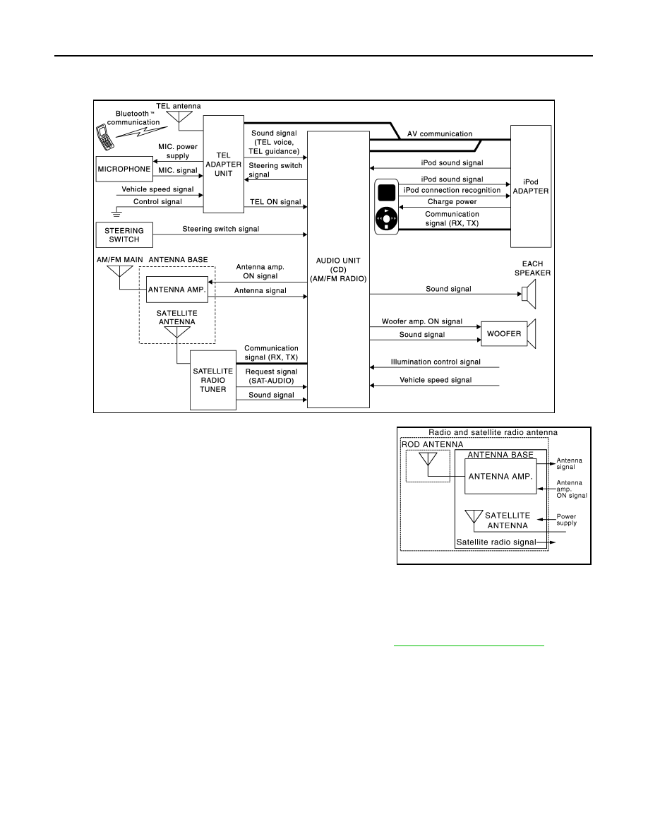
System Diagram
INFOID:0000000004940215
NOTE:
An antenna base integrated with radio antenna amp. and satellite
radio antenna is adopted.
System Description
INFOID:0000000004940216
• The connection between cellular phone and TEL adapter unit is performed with Bluetooth
™
communication.
• The voice guidance signal is input from the TEL adapter unit to the audio unit and output to the front speaker
when operating the telephone.
• TEL adapter unit has the on board self-diagnosis function. Refer to
AV-23, "Diagnosis Description"
.
WHEN RECEIVING A CALL
TEL voice signal received with the cellular phone is input from TEL antenna via TEL adapter unit to audio unit
with Bluetooth
™
communication and output to the front speaker. The operation is performed with the steering
switch or voice recognition function.
WHEN A CALL IS ORIGINATED
Speech sound (TEL voice signal) is input from the microphone to the TEL adapter unit. It is input from the TEL
antenna via Bluetooth
™
communication to the cellular phone. It is transmitted to the phone on the other side.
The operation is performed with the steering switch or voice recognition function.
JPNIA1642GB
JSNIA1062GB
Revision: 2009 March
2009 Z12
AV
HANDS-FREE PHONE SYSTEM
AV-17
< SYSTEM DESCRIPTION >
[AUDIO SYSTEM]
C
D
E
F
G
H
I
J
K
L
M
B
A
O
P
Component Parts Location
INFOID:0000000004940217
Component Description
INFOID:0000000004940218
1.
Tweeter LH
2.
Front door speaker LH
3.
Rear door speaker LH
4.
Antenna rod
5.
Antenna base (antenna amp. and
satellite antenna)
6.
Woofer
7.
Satellite radio tuner
8.
Rear door speaker RH
9.
TEL adapter unit
10. TEL antenna
11. Front door speaker RH
12. Tweeter LH
13. Audio unit
14. Microphone
15. Steering switch
16. iPod adapter
17. iPod connector
A.
Luggage side RH
B.
Floor spacer is removed condition.
C.
A/C finisher is removed condition.
JPNIA1721ZZ
Part name
Description
Audio unit
• Inputs TEL voice signal or voice guidance signal from TEL adapter unit and
outputs it to the front speaker during reception.
• Audio unit and TEL adapter unit exchange data by AV communication.
• Inputs steering switch signal (operation signal) from steering switch and out-
puts it to TEL adapter unit.
Front door speaker
Receives TEL voice and voice guidance signals from audio unit.
Tweeter
Steering switch
• The hands-free phone system can be operated.
• Steering switch signal (operation signal) is output to TEL adapter unit through
audio unit.
Revision: 2009 March
2009 Z12

AV-18
< SYSTEM DESCRIPTION >
[AUDIO SYSTEM]
HANDS-FREE PHONE SYSTEM
Microphone
• Uses when operating the hands-free phone.
• Outputs microphone signal (TEL voice signal) to the TEL adapter unit.
• The power (microphone power supply) is supplied from the TEL adapter unit.
TEL adapter unit
• Inputs the TEL voice signal from TEL antenna during reception and outputs
into the audio unit.
• Inputs the TEL voice signal from microphone during speech recognition and
outputs it to the TEL antenna.
TEL antenna
Connects with the cellular phone via Bluetooth
™
communication and communi-
cates the TEL voice signal.
Part name
Description
Revision: 2009 March
2009 Z12
AV
DIAGNOSIS SYSTEM (AUDIO UNIT)
AV-19
< SYSTEM DESCRIPTION >
[AUDIO SYSTEM]
C
D
E
F
G
H
I
J
K
L
M
B
A
O
P
DIAGNOSIS SYSTEM (AUDIO UNIT)
MODELS WITH iPod® CONNECTION FUNCTION
MODELS WITH iPod® CONNECTION FUNCTION : Diagnosis Description
INFOID:0000000004940219
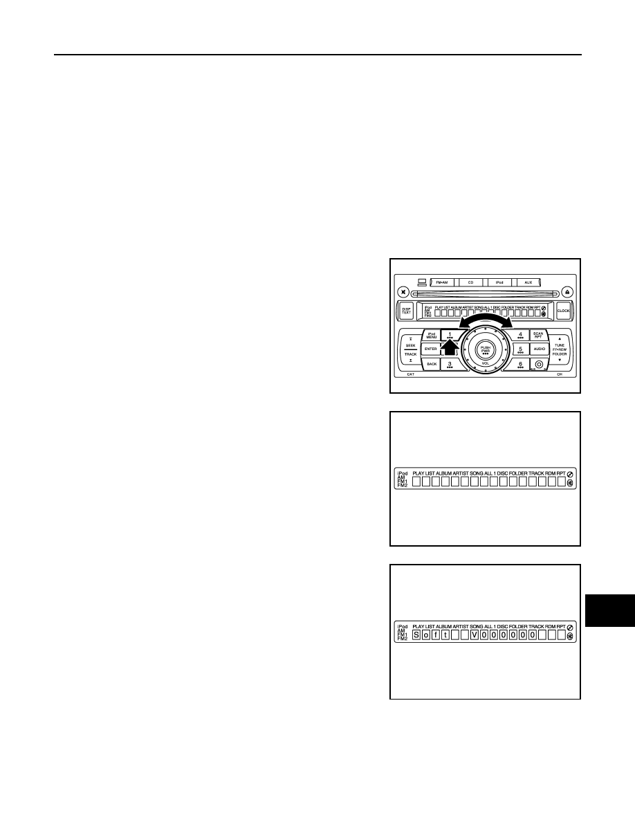
AUDIO UNIT SELF-DIAGNOSIS FUNCTION
Self-diagnosis mode can check the following items.
• Display all icons and segments
• Audio unit hardware/software/CD mechanism/EEPROM versions
• Satellite radio version
• Audio CD changer version
• iPod hardware/software versions
Operation Procedure
1.
Turn ignition switch to the ON position.
2.
Turn the audio unit off.
3.
While pressing the “1” button, turn the volume control dial clock-
wise or counterclockwise 30 clicks or more. When the self-diag-
nosis mode is started, a short beep will be heard.
4.
Initially, all display segments will be illuminated.
5.
Press the “DISP TEXT” switch to enter version diagnostics.
“Soft” (audio software version) is displayed.
JPNIA1650ZZ
JPNIA1651ZZ
JPNIA1652ZZ
Revision: 2009 March
2009 Z12
AV-20
< SYSTEM DESCRIPTION >
[AUDIO SYSTEM]
DIAGNOSIS SYSTEM (AUDIO UNIT)
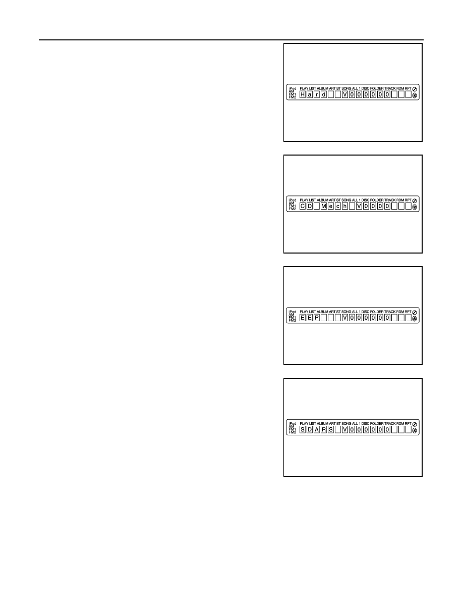
6.
Press the “DISP TEXT” switch again to display the “Hard” (audio
hardware version).
7.
Press the “DISP TEXT” switch again to display the “CD Mech”
(CD mechanism version).
8.
Press the “DISP TEXT” switch again to display the “EEP” (audio
unit EEPROM version).
9.
Press the “DISP TEXT” switch again to display the “SDARS”
(satellite radio version).
JPNIA1653ZZ
JPNIA1654ZZ
JPNIA1655ZZ
JPNIA1656ZZ
Revision: 2009 March
2009 Z12
AV
DIAGNOSIS SYSTEM (AUDIO UNIT)
AV-21
< SYSTEM DESCRIPTION >
[AUDIO SYSTEM]
C
D
E
F
G
H
I
J
K
L
M
B
A
O
P
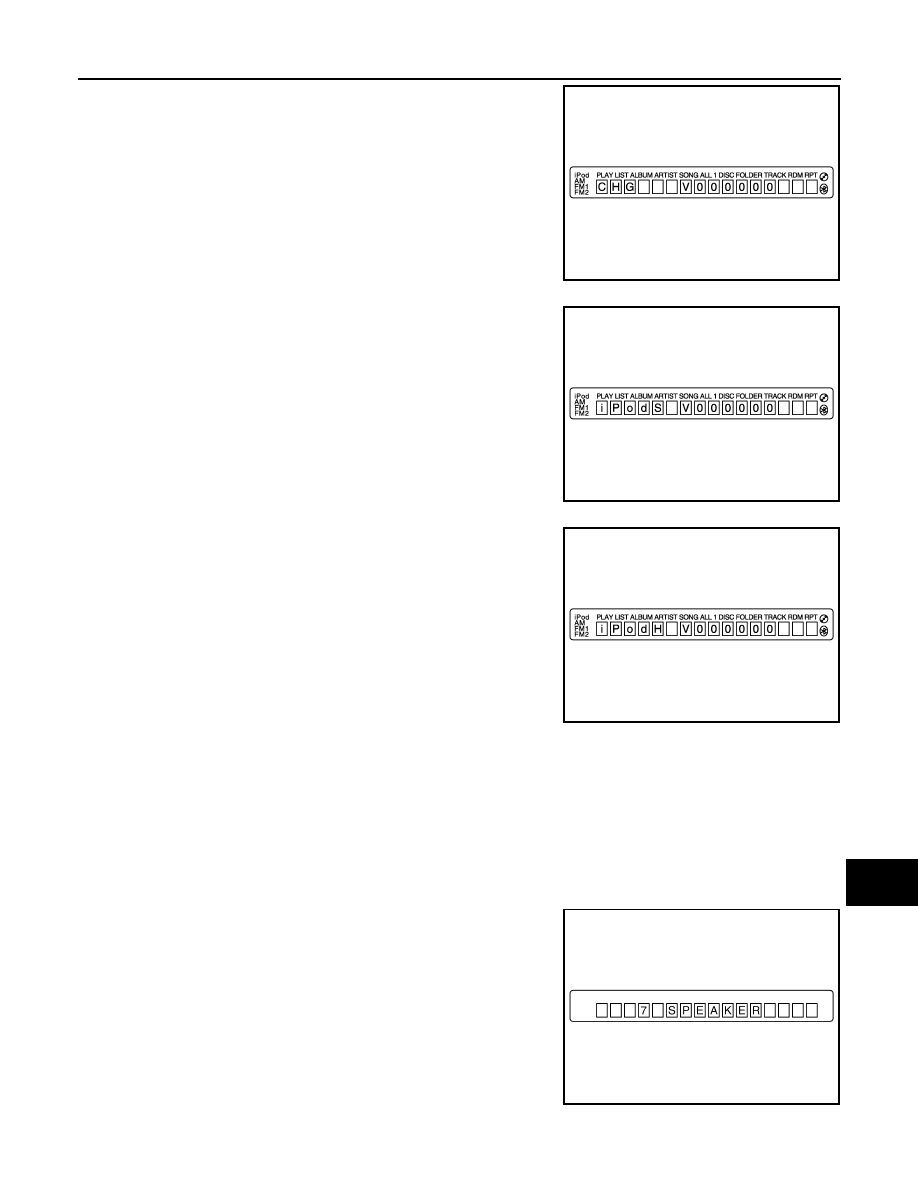
10. Press the “DISP TEXT” switch again to display the “CHG” (audio
CD changer version). If audio CD changer is not connected,
“FFFFFF” is displayed.
11. Press the “DISP TEXT” switch again to display the “iPodS” (iPod
software version). “FFFFFF” is displayed when communication
signals between the audio unit and iPod adapter include a mal-
function.
12. Press the “DISP TEXT” switch again to display the “iPodH” (iPod
hardware version). “FFFFFF” is displayed when communication
signals between the audio unit and iPod adapter include a mal-
function.
Finishing Self-diagnosis Mode
Self-diagnosis Mode is canceled when turning ignition switch OFF.
SWITCHING OF THE SPEAKER SETTING OF THE AUDIO UNIT
The speaker setting of the audio unit is selectable between “7 SPEAKER” (models with woofer) and “6
SPEAKER” (models without woofer).
Operation Procedure
1.
Turn ignition switch to the ON position.
2.
Turn the audio unit off.
3.
While pressing the “1” , “6” , and “AUDIO” buttons. When the
speaker setting is changed, setting after a change is displayed.
JPNIA1657ZZ
JPNIA1658ZZ
JPNIA1659ZZ
JPNIA1734ZZ
Revision: 2009 March
2009 Z12
AV-22
< SYSTEM DESCRIPTION >
[AUDIO SYSTEM]
DIAGNOSIS SYSTEM (AUDIO UNIT)
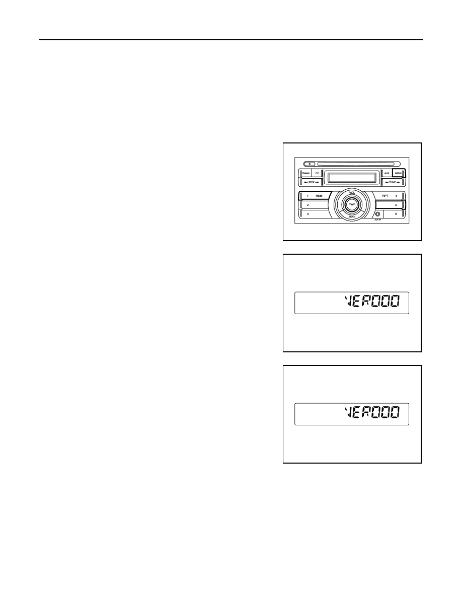
MODELS WITHOUT iPod® CONNECTION FUNCTION
MODELS WITHOUT iPod® CONNECTION FUNCTION : Diagnosis Description
INFOID:0000000004941271
Self-diagnosis mode can check the following items.
• Audio unit software version
• Audio CD changer version
OPERATION PROCEDURE
1.
Turn ignition switch to the ON position.
2.
Turn the audio unit off.
3.
Press “PWR” button while pressing “MENU”, “1” and “5” buttons.
When the self-diagnosis mode is started, a short beep will be
heard.
4.
Initially, Audio software version is displayed.
5.
Press the “PWR” button to display the audio CD changer ver-
sion. If audio CD changer is not connected, “FF” is displayed.
Finishing Self-diagnosis Mode
Self-diagnosis mode is canceled when turning ignition switch OFF.
JSNIA1923ZZ
JSNIA1924ZZ
JSNIA1924ZZ
Revision: 2009 March
2009 Z12

AV
DIAGNOSIS SYSTEM (TEL ADAPTER UNIT)
AV-23
< SYSTEM DESCRIPTION >
[AUDIO SYSTEM]
C
D
E
F
G
H
I
J
K
L
M
B
A
O
P
DIAGNOSIS SYSTEM (TEL ADAPTER UNIT)
Diagnosis Description
INFOID:0000000004940220
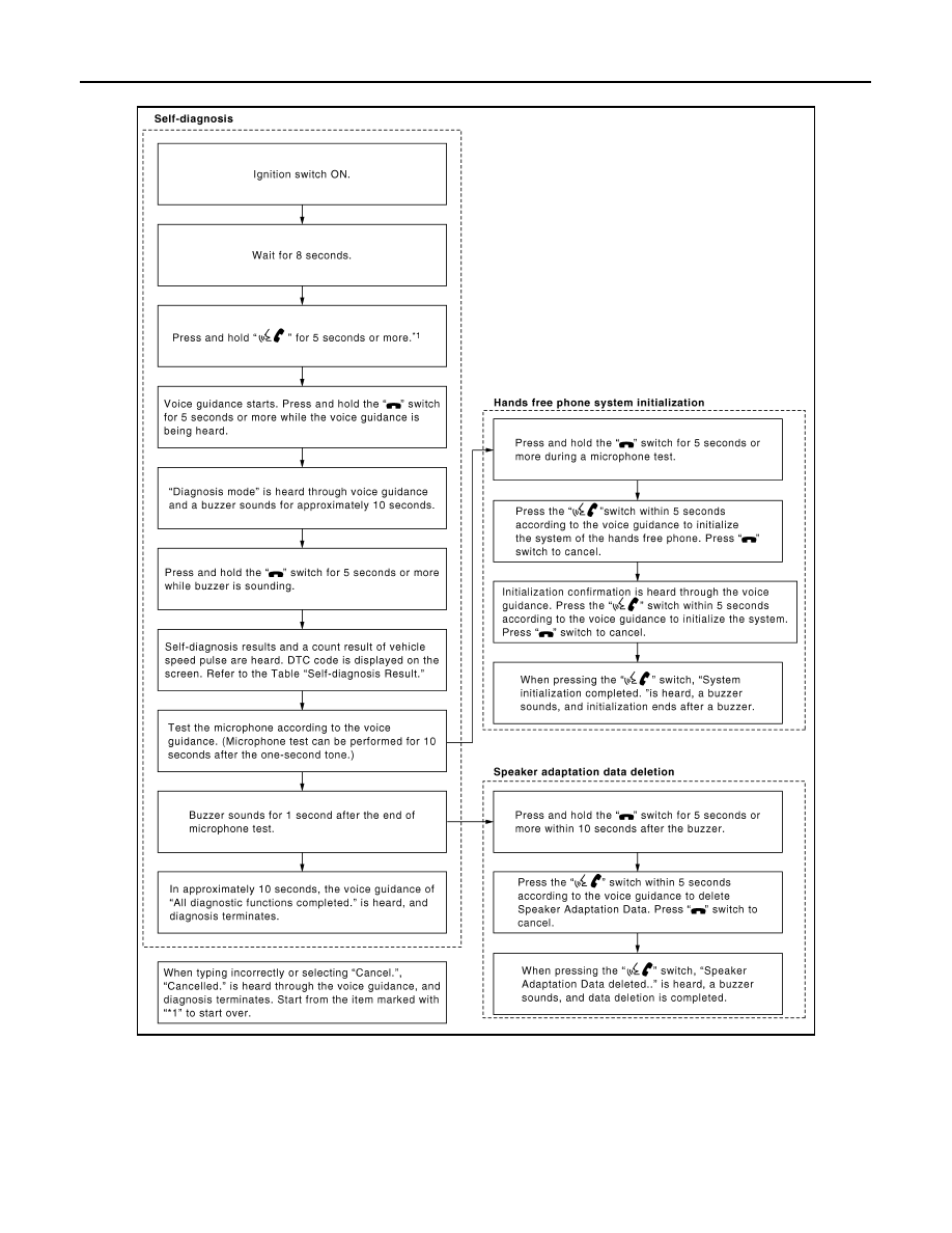
HANDS-FREE PHONE SYSTEM ON BOARD DIAGNOSIS
During on board diagnosis the diagnosis function of TEL adapter unit starts with the operation of the steering
switch and performs the diagnosis when ignition switch ACC.
ON BOARD DIAGNOSIS ITEM
The on board diagnosis has 3 modes: the self-diagnosis mode that performs the trouble diagnosis, the
speaker adaptation data deleting mode and the hands-free phone system initialization mode.
CAUTION:
• Perform the diagnosis with the vehicle stopped.
• Perform STEP2 if necessary.
SELF-DIAGNOSIS RESULTS
Self-diagnosis mode reads out the self-diagnosis results and indicates DTC on the audio screen.
NOTE:
• Error count is read out simultaneously when reading out the DTC name.
• The errors are read out continuously when some errors occur at the same time. The DTC displays are com-
bined and displayed. For example, DTC 01100 is displayed when DTC 01000 and DTC 00100 are indicated
at the same time.
Self-diagnosis results
The Details of Error Count
The error count guides “0” when the error occurs. The next time it counts up “1” if it is normal with the ignition
switch ON. It continues the count up unless the initialization of hands-free phone system is performed.
STEP
MODE
Description
STEP 1
Self-diagnosis
The self-diagnosis mode performs the microphone test and
the diagnosis of TEL adapter unit, TEL antenna and steering
switch, and then reads out the results with the sound and in-
dicates them on the audio screen.
STEP 2
Hands-free phone system initialization
Hands-free phone system initialization mode can perform
the initialization of hands-free phone system.
Speaker adaptation data deleting
The speaker adaptation data deleting mode can delete the
speaker adaptation data.
DTC
(Audio screen)
Failure massage
Possible causes
DTC 10000
Internal failure
TEL adapter unit
DTC 01000
Bluetooth antenna open
TEL antenna
DTC 00100
Bluetooth antenna shorted
DTC 00010
Button ladder A is stuck
Steering switch
DTC 00001
Button ladder B is stuck
DTC 00000
There are no failure records to report
—
Revision: 2009 March
2009 Z12
AV-24
< SYSTEM DESCRIPTION >
[AUDIO SYSTEM]
DIAGNOSIS SYSTEM (TEL ADAPTER UNIT)
FLOW CHART OF TROUBLE DIAGNOSIS
JSNIA0169GB
Revision: 2009 March
2009 Z12

AV
POWER SUPPLY AND GROUND CIRCUIT
AV-25
< DTC/CIRCUIT DIAGNOSIS >
[AUDIO SYSTEM]
C
D
E
F
G
H
I
J
K
L
M
B
A
O
P
DTC/CIRCUIT DIAGNOSIS
POWER SUPPLY AND GROUND CIRCUIT
AUDIO UNIT
AUDIO UNIT : Diagnosis Procedure
INFOID:0000000004940221
1.
CHECK FUSE
Check that the following fuses of the audio unit are not blown.
Is inspection result OK?
YES
>> GO TO 2.
NO
>> If fuse is blown, be sure to eliminate cause of malfunction before installing new fuse.
2.
CHECK AUDIO UNIT POWER SUPPLY CIRCUIT
Check voltage between the audio unit and ground.
Is inspection result OK?
YES
>> INSPECTION END
NO
>> Check harness between audio unit and fuse.
iPod ADAPTER
iPod ADAPTER : Diagnosis Procedure
INFOID:0000000005148283
1.
CHECK FUSE
Check for blown fuses.
Is the inspection result normal?
YES
>> GO TO 2.
NO
>> Be sure to eliminate the cause of malfunction before installing new fuse.
2.
CHECK POWER SUPPLY CIRCUIT
Check voltage between iPod adapter harness connector and ground.
Is the inspection result normal?
YES
>> INSPECTION END
NO
>> Check harness between iPod adapter and fuse.
SATELLITE RADIO TUNER
Power source
Fuse No.
Battery
34
Ignition switch ACC or ON
20
Signal name
Connector No.
Terminal No.
Ignition switch position
Voltage
Battery power supply
M46
19
OFF
Battery voltage
ACC power supply
7
ACC
Battery voltage
Power source
Fuse No.
Battery
34
Ignition switch ACC or ON
20
Signal name
Connector No.
Terminal No.
Ignition switch position
Voltage
Battery power supply
M99
5
OFF
Battery voltage
ACC power supply
3
ACC
Revision: 2009 March
2009 Z12

AV-26
< DTC/CIRCUIT DIAGNOSIS >
[AUDIO SYSTEM]
POWER SUPPLY AND GROUND CIRCUIT
SATELLITE RADIO TUNER : Diagnosis Procedure
INFOID:0000000004940223
1.
CHECK FUSES
Check that the following fuses of the satellite radio tuner are not blown.
Is inspection result OK?
YES
>> GO TO 2.
NO
>> If fuse is blown, be sure to eliminate cause of malfunction before installing new fuse.
2.
CHECK POWER SUPPLY CIRCUIT
Check voltage between the satellite radio tuner and ground.
Is inspection result OK?
YES
>> INSPECTION END
NO
>> Check harness between satellite radio tuner and fuse.
TEL ADAPTER UNIT
TEL ADAPTER UNIT : Diagnosis Procedure
INFOID:0000000004940224
1.
CHECK FUSES
Check that the following fuses of the TEL adapter unit are not blown.
Is inspection result OK?
YES
>> GO TO 2.
NO
>> If fuse is blown, be sure to eliminate cause of malfunction before installing new fuse.
2.
CHECK POWER SUPPLY CIRCUIT
Check voltage between TEL adapter unit harness connector and ground.
Is inspection result OK?
YES
>> GO TO 3.
NO
>> Check harness between TEL adapter unit and fuse.
3.
CHECK GROUND CIRCUIT
1.
Turn ignition switch OFF.
2.
Disconnect TEL adapter unit connector.
3.
Check continuity between TEL adapter unit harness connector and ground.
Power source
Fuse No.
Battery
34
Ignition switch ACC or ON
20
Signal name
Connector No.
Terminal No.
Ignition switch position
Voltage
Battery power supply
B73
12
OFF
Battery voltage
ACC power supply
16
ACC
Battery voltage
Power source
Fuse No.
Battery
34
Ignition switch ACC or ON
20
Ignition switch ON or START
2
Signal name
Connector No.
Terminal No.
Ignition switch position
Voltage
Battery power supply
B54
1
OFF
Battery voltage
ACC power supply
2
ACC
Battery voltage
Ignition signal
3
ON
Battery voltage
Revision: 2009 March
2009 Z12

AV
POWER SUPPLY AND GROUND CIRCUIT
AV-27
< DTC/CIRCUIT DIAGNOSIS >
[AUDIO SYSTEM]
C
D
E
F
G
H
I
J
K
L
M
B
A
O
P
Is inspection result OK?
YES
>> INSPECTION END
NO
>> Repair harness or connector.
Signal name
Connector No.
Terminal No.
Ignition switch position
Continuity
Ground
B54
4
OFF
Existed
Revision: 2009 March
2009 Z12

AV-28
< DTC/CIRCUIT DIAGNOSIS >
[AUDIO SYSTEM]
STEERING SWITCH SIGNAL A CIRCUIT (STEERING SWITCH TO AUDIO UNIT)
STEERING SWITCH SIGNAL A CIRCUIT (STEERING SWITCH TO AUDIO
UNIT)
Description
INFOID:0000000004940225
• Transmits the steering switch signal to audio unit.
• Transmits the steering switch signal to TEL adapter unit through audio unit (models with hands-free phone
system).
Diagnosis Procedure
INFOID:0000000004940226
1.
CHECK STEERING SWITCH SIGNAL A CIRCUIT
1.
Turn ignition switch OFF.
2.
Disconnect audio unit connector and spiral cable connector.
3.
Check continuity between audio unit harness connector and spiral cable harness connector.
4.
Check continuity between audio unit harness connector and ground.
Is the inspection result normal?
YES
>> GO TO 2.
NO
>> Repair harness or connector.
2.
CHECK SPIRAL CABLE
Check spiral cable.
Is the inspection result normal?
YES
>> GO TO 3.
NO
>> Replace spiral cable.
3.
CHECK AUDIO UNIT VOLTAGE
1.
Connect AV control unit connector and spiral cable connector.
2.
Turn ignition switch ON.
3.
Check voltage between audio unit harness connector.
Is the inspection result normal?
YES
>> GO TO 4.
NO
>> Replace audio unit.
4.
CHECK STEERING SWITCH
1.
Turn ignition switch OFF.
2.
Check steering switch. Refer to
.
Is the inspection result normal?
YES
>> INSPECTION END
NO
>> Replace steering switch.
Audio unit
Spiral cable
Continuity
Connector
Terminal
Connector
Terminal
M46
6
M33
24
Existed
Audio unit
Ground
Continuity
Connector
Terminal
M46
6
Not existed
(+)
(
−
)
Voltage
(Approx.)
Audio unit
Audio unit
Connector
Terminal
Connector
Terminal
M46
6
M46
15
3.2 V
Revision: 2009 March
2009 Z12
AV
STEERING SWITCH SIGNAL A CIRCUIT (STEERING SWITCH TO AUDIO UNIT)
AV-29
< DTC/CIRCUIT DIAGNOSIS >
[AUDIO SYSTEM]
C
D
E
F
G
H
I
J
K
L
M
B
A
O
P
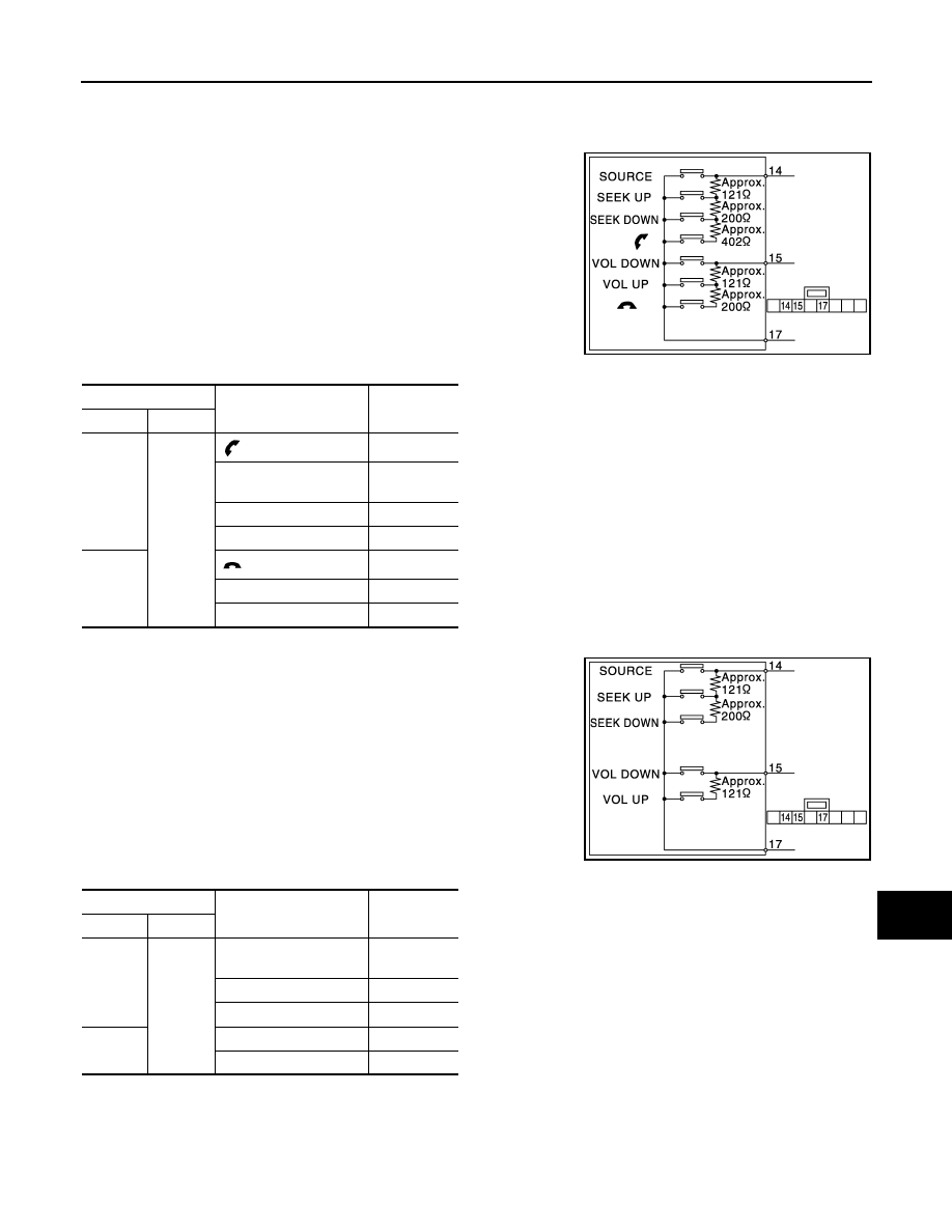
Component Inspection
INFOID:0000000004940227
MODELS WITH HANDS-FREE PHONE SYSTEM
Measure the resistance between the steering switch connector.
Standard
MODELS WITHOUT HANDS-FREE PHONE SYSTEM
Measure the resistance between the steering switch connector.
Standard
JPNIA1780GB
Steering switch
Condition
Resistance
(Approx.)
Ω
Terminal
Terminal
14
17
switch ON
709 – 737
SEEK DOWN switch
ON
315 – 327
SEEK UP switch ON
119 – 123
SOURCE switch ON
0
15
switch ON
315 – 327
VOL UP switch ON
119 – 123
VOL DOWN switch ON
0
JSNIA1145GB
Steering switch
Condition
Resistance
(Approx.)
Ω
Terminal
Terminal
14
17
SEEK DOWN switch
ON
315 – 327
SEEK UP switch ON
119 – 123
SOURCE switch ON
0
15
VOL UP switch ON
119 – 123
VOL DOWN switch ON
0
Revision: 2009 March
2009 Z12

AV-30
< DTC/CIRCUIT DIAGNOSIS >
[AUDIO SYSTEM]
STEERING SWITCH SIGNAL B CIRCUIT (STEERING SWITCH TO AUDIO UNIT)
STEERING SWITCH SIGNAL B CIRCUIT (STEERING SWITCH TO AUDIO
UNIT)
Description
INFOID:0000000005148285
• Transmits the steering switch signal to audio unit.
• Transmits the steering switch signal to TEL adapter unit through audio unit (models with hands-free phone
system).
Diagnosis Procedure
INFOID:0000000004940229
1.
CHECK STEERING SWITCH SIGNAL B CIRCUIT
1.
Turn ignition switch OFF.
2.
Disconnect audio unit connector and spiral cable connector.
3.
Check continuity between audio unit harness connector and spiral cable harness connector.
4.
Check continuity between audio unit harness connector and ground.
Is the inspection result normal?
YES
>> GO TO 2.
NO
>> Repair harness or connector.
2.
CHECK SPIRAL CABLE
Check spiral cable.
Is the inspection result normal?
YES
>> GO TO 3.
NO
>> Replace spiral cable.
3.
CHECK AUDIO UNIT VOLTAGE
1.
Connect audio unit connector and spiral cable connector.
2.
Turn ignition switch ON.
3.
Check voltage between audio unit harness connector.
Is the inspection result normal?
YES
>> GO TO 4.
NO
>> Replace audio unit.
4.
CHECK STEERING SWITCH
1.
Turn ignition switch OFF.
2.
Check steering switch. Refer to
.
Is the inspection result normal?
YES
>> INSPECTION END
NO
>> Replace steering switch.
Audio unit
Spiral cable
Continuity
Connector
Terminal
Connector
Terminal
M46
16
M33
31
Existed
Audio unit
Ground
Continuity
Connector
Terminal
M46
16
Not existed
(+)
(
−
)
Voltage
(Approx.)
Audio unit
Audio unit
Connector
Terminal
Connector
Terminal
M46
16
M46
15
3.2 V
Revision: 2009 March
2009 Z12

AV
STEERING SWITCH SIGNAL B CIRCUIT (STEERING SWITCH TO AUDIO UNIT)
AV-31
< DTC/CIRCUIT DIAGNOSIS >
[AUDIO SYSTEM]
C
D
E
F
G
H
I
J
K
L
M
B
A
O
P
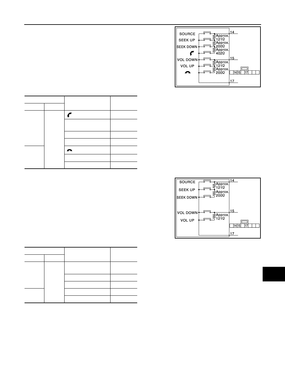
Component Inspection
INFOID:0000000004940230
MODELS WITH HANDS-FREE PHONE SYSTEM
Measure the resistance between the steering switch connector.
Standard
MODELS WITHOUT HANDS-FREE PHONE SYSTEM
Measure the resistance between the steering switch connector.
Standard
JPNIA1780GB
Steering switch
Condition
Resistance
(Approx.)
Ω
Terminal
Terminal
14
17
switch ON
709 – 737
SEEK DOWN switch
ON
315 – 327
SEEK UP switch ON
119 – 123
SOURCE switch ON
0
15
switch ON
315 – 327
VOL UP switch ON
119 – 123
VOL DOWN switch ON
0
JSNIA1145GB
Steering switch
Condition
Resistance
(Approx.)
Ω
Terminal
Terminal
14
17
SEEK DOWN switch
ON
315 – 327
SEEK UP switch ON
119 – 123
SOURCE switch ON
0
15
VOL UP switch ON
119 – 123
VOL DOWN switch ON
0
Revision: 2009 March
2009 Z12

AV-32
< DTC/CIRCUIT DIAGNOSIS >
[AUDIO SYSTEM]
STEERING SWITCH SIGNAL GND CIRCUIT (STEERING SWITCH TO AUDIO
UNIT)
STEERING SWITCH SIGNAL GND CIRCUIT (STEERING SWITCH TO AU-
DIO UNIT)
Description
INFOID:0000000004940231
• Transmits the steering switch signal to audio unit.
• Transmits the steering switch signal to TEL adapter unit through audio unit (models with hands-free phone
system).
Diagnosis Procedure
INFOID:0000000004940232
1.
CHECK STEERING SWITCH SIGNAL GND CIRCUIT
1.
Turn ignition switch OFF.
2.
Disconnect audio unit connector and spiral cable connector.
3.
Check continuity between audio unit harness connector and spiral cable harness connector.
4.
Connect audio unit connector.
Is the inspection result normal?
YES
>> GO TO 2.
NO
>> Repair harness or connector.
2.
CHECK SPIRAL CABLE
Check spiral cable.
Is the inspection result normal?
YES
>> GO TO 3.
NO
>> Replace spiral cable.
3.
CHECK GROUND CIRCUIT
1.
Connect audio unit connector.
2.
Check continuity between audio unit harness connector and ground.
Is the inspection result normal?
YES
>> GO TO 4.
NO
>> Replace audio unit.
4.
CHECK STEERING SWITCH
Check steering switch. Refer to
.
Is the inspection result normal?
YES
>> INSPECTION END
NO
>> Replace steering switch.
Component Inspection
INFOID:0000000004940233
MODELS WITH HANDS-FREE PHONE SYSTEM
Audio unit
Spiral cable
Continuity
Connector
Terminal
Connector
Terminal
M46
15
M33
33
Existed
Audio unit
Ground
Continuity
Connector
Terminal
M46
15
Existed
Revision: 2009 March
2009 Z12
AV
STEERING SWITCH SIGNAL GND CIRCUIT (STEERING SWITCH TO AUDIO
UNIT)
AV-33
< DTC/CIRCUIT DIAGNOSIS >
[AUDIO SYSTEM]
C
D
E
F
G
H
I
J
K
L
M
B
A
O
P
Measure the resistance between the steering switch connector.
Standard
MODELS WITHOUT HANDS-FREE PHONE SYSTEM
Measure the resistance between the steering switch connector.
Standard
JPNIA1780GB
Steering switch
Condition
Resistance
(Approx.)
Ω
Terminal
Terminal
14
17
switch ON
709 – 737
SEEK DOWN switch
ON
315 – 327
SEEK UP switch ON
119 – 123
SOURCE switch ON
0
15
switch ON
315 – 327
VOL UP switch ON
119 – 123
VOL DOWN switch ON
0
JSNIA1145GB
Steering switch
Condition
Resistance
(Approx.)
Ω
Terminal
Terminal
14
17
SEEK DOWN switch
ON
315 – 327
SEEK UP switch ON
119 – 123
SOURCE switch ON
0
15
VOL UP switch ON
119 – 123
VOL DOWN switch ON
0
Revision: 2009 March
2009 Z12

AV-34
< DTC/CIRCUIT DIAGNOSIS >
[AUDIO SYSTEM]
STEERING SWITCH SIGNAL A CIRCUIT (AUDIO UNIT TO TEL ADAPTER UNIT)
STEERING SWITCH SIGNAL A CIRCUIT (AUDIO UNIT TO TEL ADAPTER
UNIT)
Description
INFOID:0000000004940234
• Transmits the steering switch signal to audio unit.
• Transmits the steering switch signal to TEL adapter unit through audio unit.
Diagnosis Procedure
INFOID:0000000004940235
1.
CHECK STEERING SWITCH SIGNAL A (AUDIO UNIT TO TEL ADAPTER UNIT) CIRCUIT
1.
Turn ignition switch OFF.
2.
Disconnect audio unit connector and TEL adapter unit connector.
3.
Check continuity between audio unit harness connector and TEL adapter unit harness connector.
4.
Check continuity between audio unit harness connector and ground.
Is the inspection result normal?
YES
>> GO TO 2.
NO
>> Repair harness or connector.
2.
CHECK AUDIO UNIT VOLTAGE
1.
Connect audio unit connector and TEL adapter unit connector.
2.
Turn ignition switch ON.
3.
Check voltage between audio unit harness connector.
Is the inspection result normal?
YES
>> Replace TEL adapter unit.
NO
>> Replace audio unit.
Audio unit
TEL adapter unit
Continuity
Connector
Terminal
Connector
Terminal
M49
51
B54
12
Existed
Audio unit
Ground
Continuity
Connector
Terminal
M49
51
Not existed
(+)
(
−
)
Voltage
(Approx.)
Audio unit
Audio unit
Connector
Terminal
Connector
Terminal
M49
51
M49
53
4.8 V
Revision: 2009 March
2009 Z12

AV
STEERING SWITCH SIGNAL B CIRCUIT (AUDIO UNIT TO TEL ADAPTER UNIT)
AV-35
< DTC/CIRCUIT DIAGNOSIS >
[AUDIO SYSTEM]
C
D
E
F
G
H
I
J
K
L
M
B
A
O
P
STEERING SWITCH SIGNAL B CIRCUIT (AUDIO UNIT TO TEL ADAPTER
UNIT)
Description
INFOID:0000000005154027
• Transmits the steering switch signal to audio unit.
• Transmits the steering switch signal to TEL adapter unit through audio unit.
Diagnosis Procedure
INFOID:0000000004940238
1.
CHECK STEERING SWITCH SIGNAL B (AUDIO UNIT TO TEL ADAPTER UNIT) CIRCUIT
1.
Turn ignition switch OFF.
2.
Disconnect audio unit connector and TEL adapter unit connector.
3.
Check continuity between audio unit harness connector and TEL adapter unit harness connector.
4.
Check continuity between audio unit harness connector and ground.
Is the inspection result normal?
YES
>> GO TO 2.
NO
>> Repair harness or connector.
2.
CHECK AUDIO UNIT VOLTAGE
1.
Connect audio unit connector and TEL adapter unit connector.
2.
Turn ignition switch ON.
3.
Check voltage between audio unit harness connector.
Is the inspection result normal?
YES
>> Replace TEL adapter unit.
NO
>> Replace audio unit.
Audio unit
TEL adapter unit
Continuity
Connector
Terminal
Connector
Terminal
M49
52
B54
13
Existed
Audio unit
Ground
Continuity
Connector
Terminal
M49
52
Not existed
(+)
(
−
)
Voltage
(Approx.)
Audio unit
Audio unit
Connector
Terminal
Connector
Terminal
M49
52
M49
53
4.8 V
Revision: 2009 March
2009 Z12

AV-36
< DTC/CIRCUIT DIAGNOSIS >
[AUDIO SYSTEM]
STEERING SWITCH SIGNAL GND CIRCUIT (AUDIO UNIT TO TEL ADAPTER
UNIT)
STEERING SWITCH SIGNAL GND CIRCUIT (AUDIO UNIT TO TEL ADAPT-
ER UNIT)
Description
INFOID:0000000005154028
• Transmits the steering switch signal to audio unit.
• Transmits the steering switch signal to TEL adapter unit through audio unit.
Diagnosis Procedure
INFOID:0000000004940241
1.
CHECK STEERING SWITCH SIGNAL GND CIRCUIT
1.
Turn ignition switch OFF.
2.
Disconnect audio unit connector and TEL adapter unit connector.
3.
Check continuity between audio unit harness connector and TEL adapter unit harness connector.
Is the inspection result normal?
YES
>> GO TO 2.
NO
>> Repair harness or connector.
2.
CHECK GROUND CIRCUIT
1.
Connect audio unit connector.
2.
Check continuity between audio unit harness connector and ground.
Is the inspection result normal?
YES
>> INSPECTION END
NO
>> Repair harness or connector.
Audio unit
TEL adapter unit
Continuity
Connector
Terminal
Connector
Terminal
M49
53
B54
14
Existed
Audio unit
Ground
Continuity
Connector
Terminal
M49
53
Existed
Revision: 2009 March
2009 Z12
AV
COMMUNICATION SIGNAL CIRCUIT
AV-37
< DTC/CIRCUIT DIAGNOSIS >
[AUDIO SYSTEM]
C
D
E
F
G
H
I
J
K
L
M
B
A
O
P
COMMUNICATION SIGNAL CIRCUIT
Description
INFOID:0000000004940243
Satellite radio tuner and audio unit are connected with a serial communication. They transmit the operation
signal from audio unit to satellite radio tuner.
Diagnosis Procedure
INFOID:0000000004940244
1.
CHECK CONTINUITY COMMUNICATION SIGNAL (AUDIO
−
SAT) CIRCUIT
1.
Turn ignition switch OFF.
2.
Disconnect satellite radio tuner connector and audio unit connector.
3.
Check continuity between satellite radio tuner harness connector and audio unit harness connector.
4.
Check continuity between satellite radio tuner harness connector and ground.
Is inspection result OK?
YES
>> GO TO 2.
NO
>> Repair harness or connector.
2.
CHECK AUDIO UNIT
1.
Connect audio unit connector.
2.
Turn ignition switch ON.
3.
Check voltage between audio unit harness connector and ground.
Is inspection result OK?
YES
>> GO TO 3.
NO
>> Replace audio unit.
3.
CHECK SATELLITE RADIO TUNER
1.
Turn ignition switch OFF.
2.
Disconnect audio unit connector, and connect satellite radio tuner connector.
3.
Turn ignition switch ON.
4.
Check voltage between satellite radio tuner harness connector and ground.
Is inspection result OK?
YES
>> GO TO 4.
NO
>> Replace satellite radio tuner.
Satellite radio tuner
Audio unit
Continuity
Connector
Terminal
Connector
Terminal
B73
9
M48
39
Existed
10
40
Existed
Satellite radio tuner
Ground
Continuity
Connector
Terminal
B73
9
Not existed
10
Audio unit
Ground
Voltage
(Approx.)
Connector
Terminal
M48
39
4.0 V
Satellite radio tuner
Ground
Voltage
(Approx)
Connector
Terminal
M73
10
7.5 V
Revision: 2009 March
2009 Z12
AV-38
< DTC/CIRCUIT DIAGNOSIS >
[AUDIO SYSTEM]
COMMUNICATION SIGNAL CIRCUIT
4.
CHECK COMMUNICATION SIGNAL (SAT
−
AUDIO)
1.
Turn ignition switch OFF.
2.
Connect audio unit connector.
3.
Turn ignition switch ON.
4.
Check signal between satellite radio tuner harness connector and ground.
Is inspection result OK?
YES
>> GO TO 5.
NO
>> Replace satellite radio tuner.
5.
CHECK COMMUNICATION SIGNAL (AUDIO
−
SAT)
Check signal between audio unit harness connector and ground.
Is inspection result OK?
YES
>> INSPECTION END
NO
>> Replace audio unit.
Satellite radio tuner
Ground
Condition
Reference value
Connector
Terminal
B73
9
When satellite radio mode is
selected.
PKIB5039J
Audio unit
Ground
Condition
Reference value
Connector
Terminal
M48
40
When satellite radio mode is
selected.
SKIA9301J
Revision: 2009 March
2009 Z12
AV
REQUEST SIGNAL CIRCUIT (SAT TO AUDIO)
AV-39
< DTC/CIRCUIT DIAGNOSIS >
[AUDIO SYSTEM]
C
D
E
F
G
H
I
J
K
L
M
B
A
O
P
REQUEST SIGNAL CIRCUIT (SAT TO AUDIO)
Description
INFOID:0000000004940245
Request signal transmits the signal to recognize the connection of satellite radio tuner from satellite radio
tuner to audio unit.
Diagnosis Procedure
INFOID:0000000004940246
1.
CHECK CONTINUITY REQUEST SIGNAL CIRCUIT
1.
Turn ignition switch OFF.
2.
Disconnect satellite radio tuner connector and audio unit connector.
3.
Check continuity between satellite radio tuner harness connector and audio unit harness connector.
4.
Check continuity between satellite radio tuner harness connector and ground.
Is inspection result OK?
YES
>> GO TO 2.
NO
>> Repair harness or connector.
2.
CHECK AUDIO UNIT
1.
Connect audio unit connector.
2.
Turn ignition switch ON.
3.
Check voltage between audio unit harness connector and ground.
Is inspection result OK?
YES
>> GO TO 3.
NO
>> Replace audio unit.
3.
CHECK CONTINUITY REQUEST SIGNAL
1.
Turn ignition switch OFF.
2.
Connect satellite radio tuner connector.
3.
Turn ignition switch ON.
4.
Check signal between satellite radio tuner harness connector and ground.
Satellite radio tuner
Audio unit
Continuity
Connector
Terminal
Connector
Terminal
B73
8
M48
38
Existed
Satellite radio tuner
Ground
Continuity
Connector
Terminal
B73
8
Not existed
Audio unit
Ground
Voltage
(Approx.)
Connector
Terminal
M48
38
4.0 V
Satellite radio tuner
Ground
Condition
Reference value
Connector
Terminal
B73
8
When satellite radio mode is
selected.
SKIA9299J
Revision: 2009 March
2009 Z12

AV-40
< DTC/CIRCUIT DIAGNOSIS >
[AUDIO SYSTEM]
REQUEST SIGNAL CIRCUIT (SAT TO AUDIO)
Is inspection result OK?
YES
>> INSPECTION END
NO
>> Replace satellite radio tuner.
Revision: 2009 March
2009 Z12

AV
WOOFER AMP. ON SIGNAL CIRCUIT
AV-41
< DTC/CIRCUIT DIAGNOSIS >
[AUDIO SYSTEM]
C
D
E
F
G
H
I
J
K
L
M
B
A
O
P
WOOFER AMP. ON SIGNAL CIRCUIT
Description
INFOID:0000000004940249
When the audio system is turned on, a voltage signal is supplied from the audio unit to the woofer. When this
signal is received, the woofer will turn on.
Diagnosis Procedure
INFOID:0000000004940250
1.
CHECK CONTINUITY WOOFER AMP. ON SIGNAL CIRCUIT
1.
Turn ignition switch OFF.
2.
Disconnect audio unit connector and woofer connector.
3.
Check continuity between audio unit harness connector and woofer harness connector.
4.
Check continuity between woofer harness connector and ground.
Is inspection result OK?
YES
>> GO TO 2.
NO
>> Repair harness or connector.
2.
CHECK VOLTAGE AMP. ON SIGNAL
1.
Connect audio unit connector
2.
Turn ignition switch ON.
3.
Check voltage between audio unit harness connector and ground.
Is inspection result OK?
YES
>> Replace woofer.
NO
>> Replace audio unit.
Audio unit
Woofer
Continuity
Connector
Terminal
Connector
Terminal
M49
46
D127
4
Existed
Woofer
Ground
Continuity
Connector
Terminal
D127
4
Not existed
Audio unit
Ground
Voltage
(Approx.)
Connector
Terminal
M49
46
12.0 V
Revision: 2009 March
2009 Z12

AV-42
< DTC/CIRCUIT DIAGNOSIS >
[AUDIO SYSTEM]
MICROPHONE SIGNAL CIRCUIT
MICROPHONE SIGNAL CIRCUIT
Description
INFOID:0000000004940251
TEL adapter unit supplies power to microphone. The microphone transmits the sound voice to the TEL
adapter unit.
Diagnosis Procedure
INFOID:0000000004940252
1.
CHECK CONTINUITY BETWEEN TEL ADAPTER UNIT AND MICROPHONE CIRCUIT
1.
Turn ignition switch OFF.
2.
Disconnect TEL adapter unit connector and microphone connector.
3.
Check continuity between TEL adapter unit harness connector and microphone harness connector.
4.
Check continuity between TEL adapter unit harness connector and ground.
Is inspection result OK?
YES
>> GO TO 2.
NO
>> Repair harness or connector.
2.
CHECK MICROPHONE POWER SUPPLY
1.
Connect TEL adapter unit connector.
2.
Turn ignition switch ON.
3.
Check voltage between TEL adapter unit harness connector and ground.
Is inspection result OK?
YES
>> GO TO 3.
NO
>> Replace TEL adapter unit.
3.
CHECK MICROPHONE SIGNAL
1.
Turn ignition switch OFF.
2.
Connect microphone connector.
3.
Turn ignition switch ON.
4.
Check signal between TEL adapter unit harness connector.
TEL adapter unit
Microphone
Continuity
Connector
Terminal
Connector
Terminal
B54
7
R21
1
Existed
8
2
29
4
TEL adapter unit
Ground
Continuity
Connector
Terminal
B54
7
Not existed
29
TEL adapter unit
Ground
Voltage
(Approx.)
Connector
Terminal
B54
29
5.0 V
Revision: 2009 March
2009 Z12
AV
MICROPHONE SIGNAL CIRCUIT
AV-43
< DTC/CIRCUIT DIAGNOSIS >
[AUDIO SYSTEM]
C
D
E
F
G
H
I
J
K
L
M
B
A
O
P
Is inspection result OK?
YES
>> INSPECTION END
NO
>> Replace microphone.
TEL adapter unit
TEL adapter unit
Condition
Reference value
Connector
Terminal
Connector
Terminal
B54
7
B54
8
Give a voice.
SKIB3609E
Revision: 2009 March
2009 Z12

AV-44
< DTC/CIRCUIT DIAGNOSIS >
[AUDIO SYSTEM]
TELEPHONE ON SIGNAL CIRCUIT
TELEPHONE ON SIGNAL CIRCUIT
Description
INFOID:0000000004940253
When telephone is being used, TEL adapter unit transmits telephone ON signal to audio unit.
Diagnosis Procedure
INFOID:0000000004940254
1.
CHECK CONTINUITY TELEPHONE ON SIGNAL CIRCUIT
1.
Turn ignition switch OFF.
2.
Disconnect TEL adapter unit connector and audio unit connector.
3.
Check continuity between TEL adapter unit harness connector and audio unit harness connector.
4.
Check continuity between TEL adapter unit harness connector and ground.
Is inspection result OK?
YES
>> GO TO 2.
NO
>> Repair harness or connector.
2.
CHECK TELEPHONE ON SIGNAL
1.
Connect audio unit connector and TEL adapter unit connector.
2.
Turn ignition switch ON.
3.
Check voltage between audio unit harness connector and ground.
Is inspection result OK?
YES
>> INSPECTION END
NO
>> Replace audio unit.
TEL adapter unit
Audio unit
Continuity
Connector
Terminal
Connector
Terminal
B54
11
M49
54
Existed
TEL adapter unit
Ground
Continuity
Connector
Terminal
B54
11
Not existed
Audio unit
Ground
Condition
Voltage
(Approx.)
Connector
Terminal
M49
54
While using hands-free
phone system
0 V
While not using hands-free
phone system
5.0 V
Revision: 2009 March
2009 Z12
AV
AUDIO UNIT
AV-45
< ECU DIAGNOSIS INFORMATION >
[AUDIO SYSTEM]
C
D
E
F
G
H
I
J
K
L
M
B
A
O
P
ECU DIAGNOSIS INFORMATION
AUDIO UNIT
Reference Value
INFOID:0000000004940255
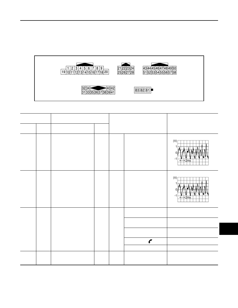
TERMINAL LAYOUT
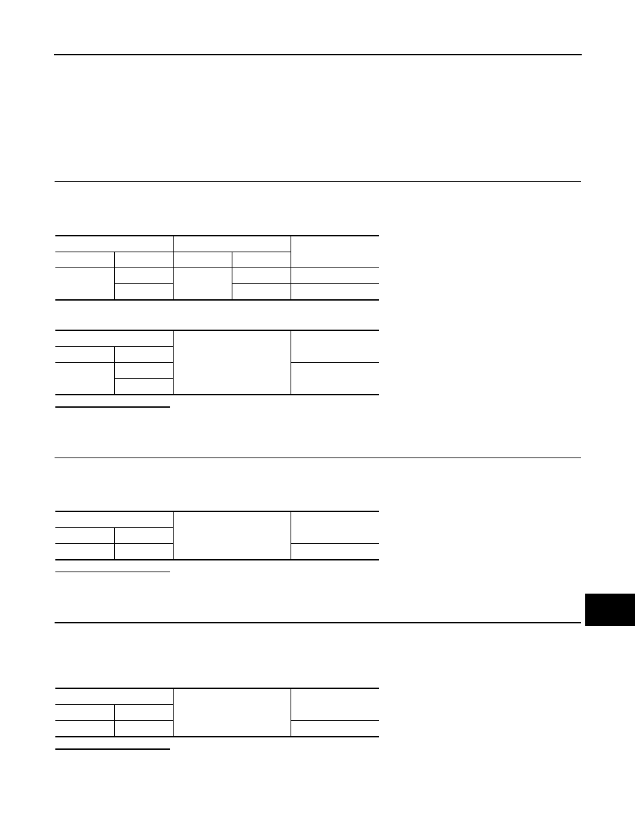
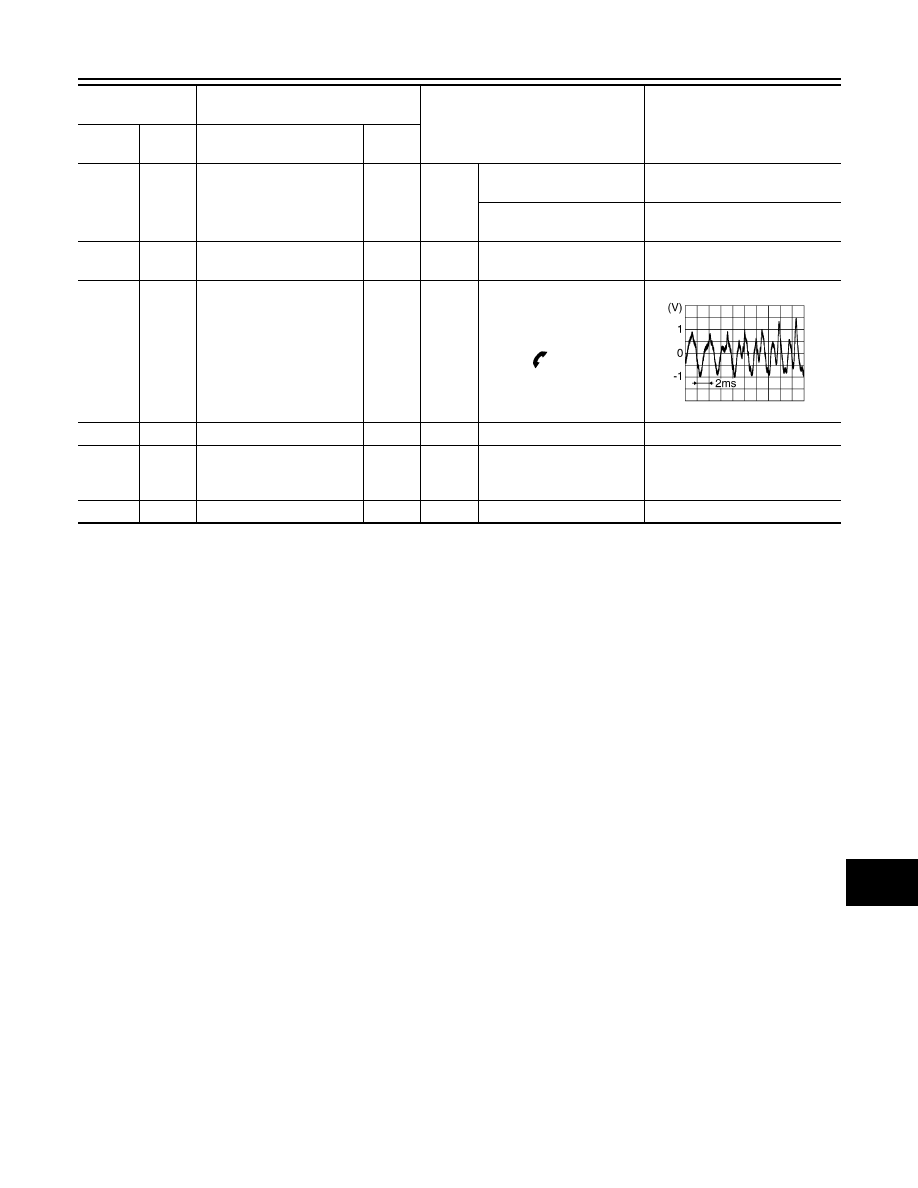
PHYSICAL VALUES
JPNIA1777ZZ
Terminal
(Wire color)
Description
Condition
Reference value
(Approx.)
+
–
Signal name
Input/
Output
2
(W)
3
(P)
Sound signal front speaker
LH
Output
Ignition
switch
ON
Sound output
4
(V)
5
(R/B)
Sound signal rear speaker
LH
Output
Ignition
switch
ON
Sound output
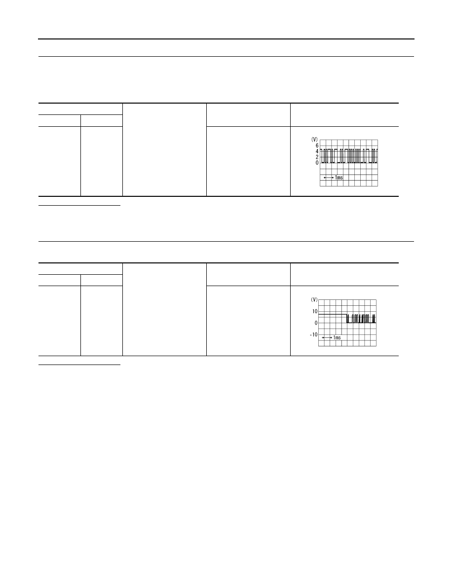
6
(W/L)
15
(L/G)
Steering switch signal A
Input
Ignition
switch
ON
Keep pressing SOURCE
switch
0 V
Keep pressing SEEK UP
switch
0.8 V
Keep pressing SEEK
DOWN switch
1.6 V
Keep pressing
switch
*
2.2 V
Except for above
3.2 V
7
(L/Y)
Ground
ACC power supply
Input
Ignition
switch
ACC
—
Battery voltage
SKIB3609E
SKIB3609E
Revision: 2009 March
2009 Z12
AV-46
< ECU DIAGNOSIS INFORMATION >
[AUDIO SYSTEM]
AUDIO UNIT
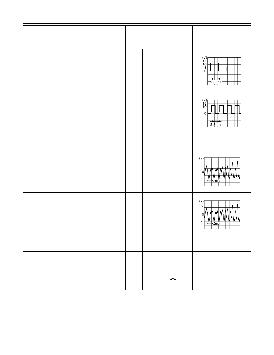
9
(W)
8
(B/R)
Illumination control signal
Input
Ignition
switch
OFF
• Lighting switch 1ST
• When meter illumination
is maximum
• Lighting switch 1ST
• When meter illumination
is step 11
• Lighting switch 1ST
• When meter illumination
is minimum
12.0 V
11
(G)
12
(R)
Sound signal front speaker
RH
Output
Ignition
switch
ON
Sound output
13
(LG)
14
(GR)
Sound signal rear speaker
RH
Output
Ignition
switch
ON
Sound output
15
(L/G)
Ground
Steering switch signal
ground
—
Ignition
switch
ON
—
0 V
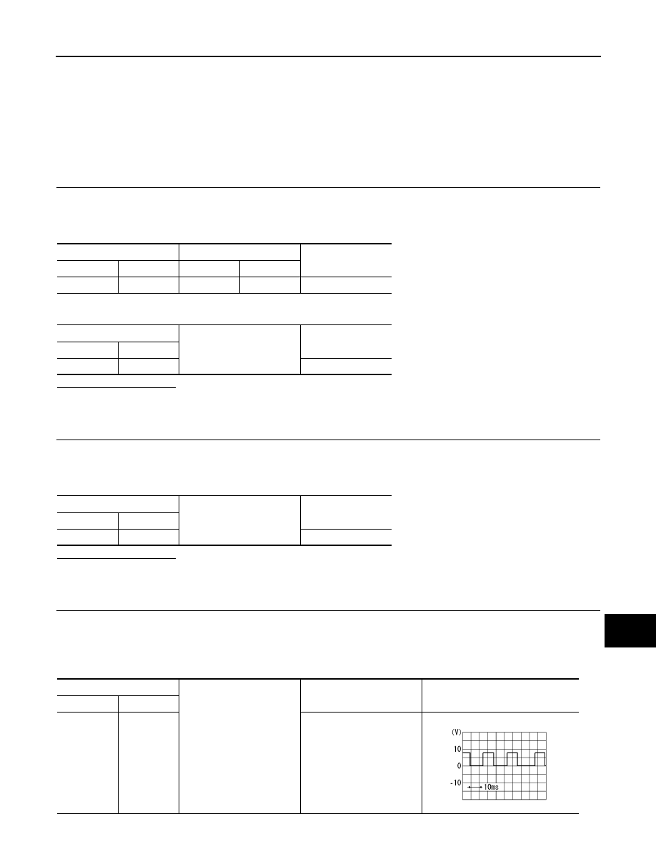
16
(GR/R)
15
(L/G)
Steering switch signal B
Input
Ignition
switch
ON
Keep pressing VOL DOWN
switch.
0 V
Keep pressing VOL UP
switch.
0.8 V
Keep pressing
switch
*
1.6 V
Except for above.
4.8 V
Terminal
(Wire color)
Description
Condition
Reference value
(Approx.)
+
–
Signal name
Input/
Output
JPNIA1687GB
JPNIA1686GB
SKIB3609E
SKIB3609E
Revision: 2009 March
2009 Z12
AV
AUDIO UNIT
AV-47
< ECU DIAGNOSIS INFORMATION >
[AUDIO SYSTEM]
C
D
E
F
G
H
I
J
K
L
M
B
A
O
P
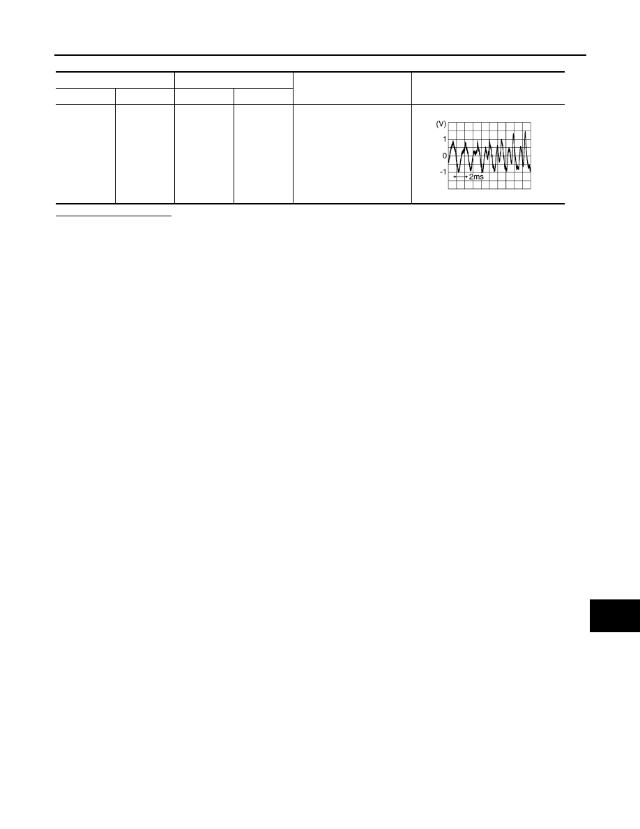
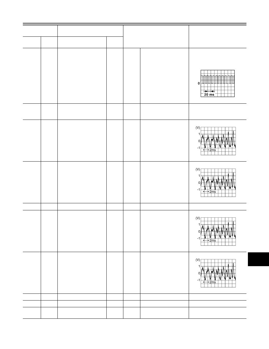
18
(L)
Ground
Vehicle speed signal
(8-pulse)
Input
Ignition
switch
ON
When vehicle speed is ap-
prox. 40 km/h (25 MPH)
NOTE:
The maximum voltage varies de-
pending on the specification
(destination unit).
19
(L)
Ground
Battery power supply
Input
Ignition
switch
OFF
—
Battery voltage
21
(R)
25
(W)
iPod sound signal LH
Input
Ignition
switch
ON
When iPod mode is select-
ed.
23
(B)
27
(G)
iPod sound signal RH
Input
Ignition
switch
ON
When iPod mode is select-
ed.
28
—
Shield
—
—
—
—
32
(R)
31
(G)
Satellite radio sound signal
LH
Input
Ignition
switch
ON
When satellite radio mode
is selected.
34
(B)
33
(W)
Satellite radio sound signal
RH
Input
Ignition
switch
ON
When satellite radio mode
is selected.
35
—
Shield
—
—
—
—
36
—
Shield
—
—
—
—
37
(W)
—
Source change
—
—
—
—
Terminal
(Wire color)
Description
Condition
Reference value
(Approx.)
+
–
Signal name
Input/
Output
JSNIA0012GB
SKIB3609E
SKIB3609E
SKIB3609E
SKIB3609E
Revision: 2009 March
2009 Z12
AV-48
< ECU DIAGNOSIS INFORMATION >
[AUDIO SYSTEM]
AUDIO UNIT
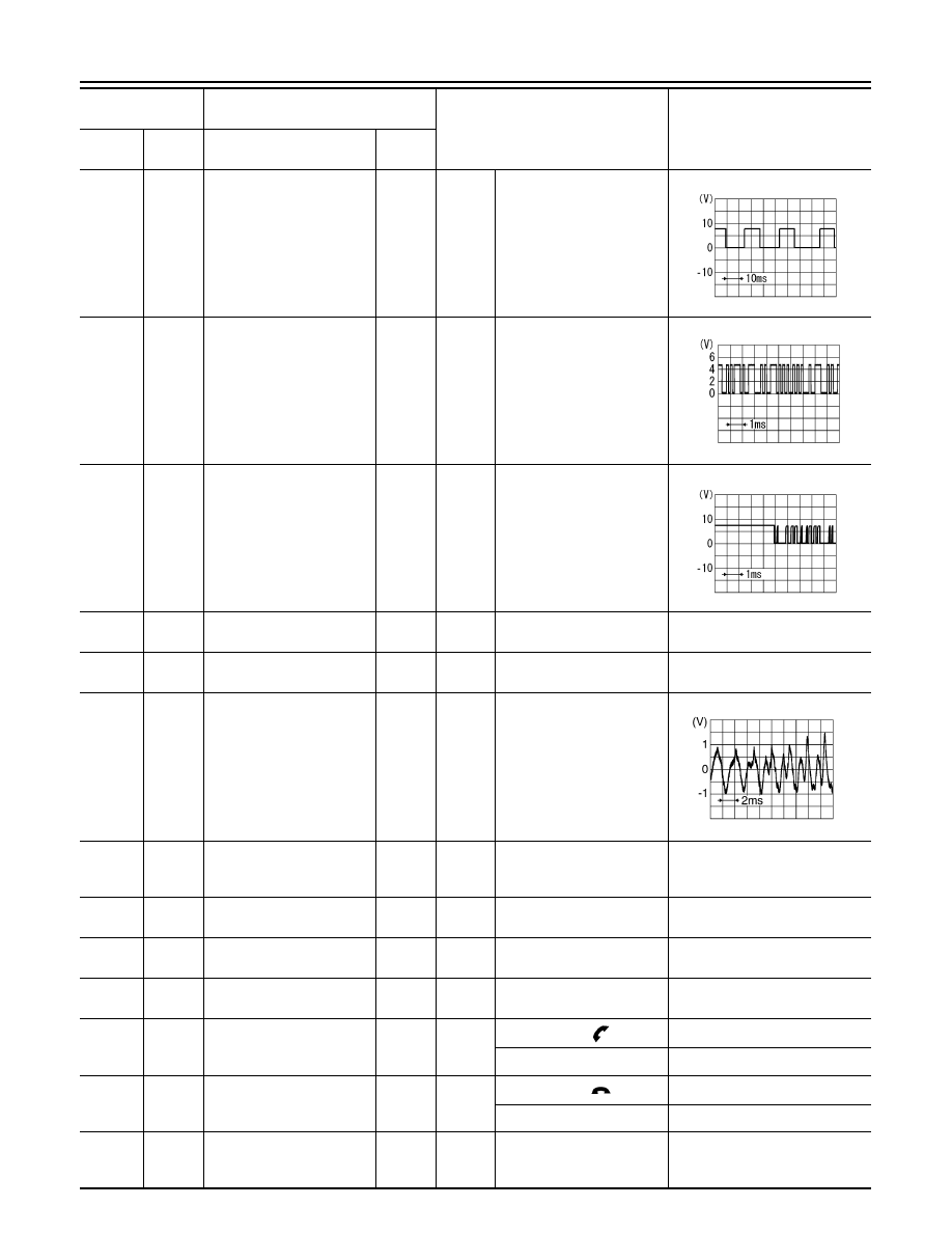
38
(G/Y)
Ground
Request signal
(SAT TO AUDIO)
Input
Ignition
switch
ON
When satellite radio mode
is selected.
39
(G/O)
Ground
Communication signal
(SAT TO AUDIO)
Input
Ignition
switch
ON
When satellite radio mode
is selected.
40
(G/R)
Ground
Communication signal
(AUDIO TO SAT)
Output
Ignition
switch
ON
When satellite radio mode
is selected.
41
(R/B)
—
Control signal
—
—
—
—
42
(Y/ W)
—
Request signal
(CHG TO AUDIO)
—
—
—
—
45
(P)
44
(L)
Sound signal woofer
Output
Ignition
switch
ON
Sound output
46
(Y/B)
Ground
Woofer amp. ON signal
Output
Ignition
switch
ON
—
12.0 V
47
(W)
—
AV communication signal
(H)
Input/
Output
—
—
—
48
(W)
—
AV communication signal
(H)
Input/
Output
—
—
—
49
(R)
—
AV communication signal
(L)
Input/
Output
—
—
—
51
(W/G)
53
(L/B)
Steering switch signal A
Output
Ignition
switch
ON
Keep pressing
switch
0 V
Except for above
4.8 V
52
(GR/R)
53
(L/B)
Steering switch signal B
Output
Ignition
switch
ON
Keep pressing
switch
0 V
Except for above
4.8 V
53
(L/B)
Ground
Steering switch signal
ground
—
Ignition
switch
ON
—
0 V
Terminal
(Wire color)
Description
Condition
Reference value
(Approx.)
+
–
Signal name
Input/
Output
SKIA9299J
PKIB5039J
SKIA9301J
SKIB3609E
Revision: 2009 March
2009 Z12
AV
AUDIO UNIT
AV-49
< ECU DIAGNOSIS INFORMATION >
[AUDIO SYSTEM]
C
D
E
F
G
H
I
J
K
L
M
B
A
O
P
*: Only for models hands-free phone system.
54
(O)
Ground
TEL ON signal
Input
Ignition
switch
ON
While using hands-free
phone system.
0 V
While not using hands-free
phone system.
5.0 V
55
(R)
—
AV communication signal
(L)
Input/
Output
—
—
—
56
(BR)
57
(Y)
Sound signal
(TEL voice, voice guid-
ance)
Input
Ignition
switch
ON
During voice guide output
with the
switch pressed.
58
—
Shield
—
—
—
—
61
Ground
Antenna amp. ON signal
Output
Ignition
switch
ON
—
12.0 V
62
—
AM–FM main
Input
—
—
—
Terminal
(Wire color)
Description
Condition
Reference value
(Approx.)
+
–
Signal name
Input/
Output
SKIB3609E
Revision: 2009 March
2009 Z12
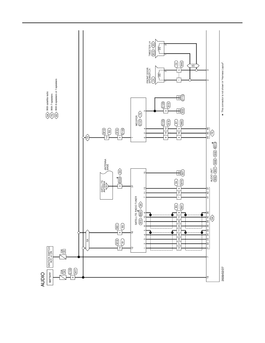
AV-50
< ECU DIAGNOSIS INFORMATION >
[AUDIO SYSTEM]
AUDIO UNIT
Wiring Diagram - AUDIO -
INFOID:0000000004940256
JCNWM2412GB
Revision: 2009 March
2009 Z12

AV
AUDIO UNIT
AV-51
< ECU DIAGNOSIS INFORMATION >
[AUDIO SYSTEM]
C
D
E
F
G
H
I
J
K
L
M
B
A
O
P
JCNWM2413GB
Revision: 2009 March
2009 Z12

AV-52
< ECU DIAGNOSIS INFORMATION >
[AUDIO SYSTEM]
AUDIO UNIT
JCNWM2414GB
Revision: 2009 March
2009 Z12

AV
AUDIO UNIT
AV-53
< ECU DIAGNOSIS INFORMATION >
[AUDIO SYSTEM]
C
D
E
F
G
H
I
J
K
L
M
B
A
O
P
JCNWM2415GB
Revision: 2009 March
2009 Z12
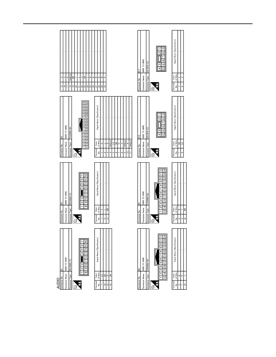
AV-54
< ECU DIAGNOSIS INFORMATION >
[AUDIO SYSTEM]
AUDIO UNIT
JCNWM2416GB
Revision: 2009 March
2009 Z12
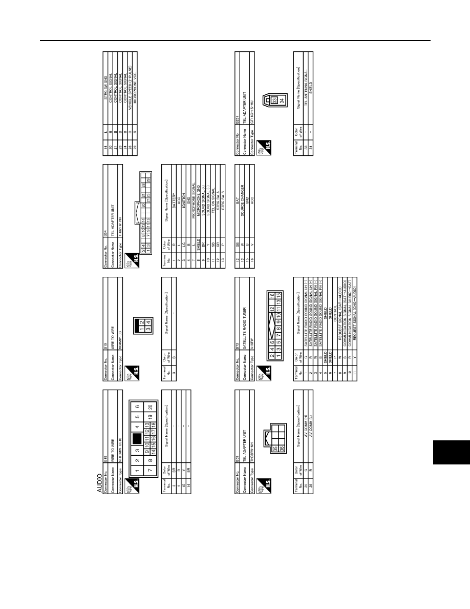
AV
AUDIO UNIT
AV-55
< ECU DIAGNOSIS INFORMATION >
[AUDIO SYSTEM]
C
D
E
F
G
H
I
J
K
L
M
B
A
O
P
JCNWM2417GB
Revision: 2009 March
2009 Z12

AV-56
< ECU DIAGNOSIS INFORMATION >
[AUDIO SYSTEM]
AUDIO UNIT
JCNWM2418GB
Revision: 2009 March
2009 Z12

AV
AUDIO UNIT
AV-57
< ECU DIAGNOSIS INFORMATION >
[AUDIO SYSTEM]
C
D
E
F
G
H
I
J
K
L
M
B
A
O
P
JCNWM2419GB
Revision: 2009 March
2009 Z12

AV-58
< ECU DIAGNOSIS INFORMATION >
[AUDIO SYSTEM]
AUDIO UNIT
JCNWM2420GB
Revision: 2009 March
2009 Z12

AV
AUDIO UNIT
AV-59
< ECU DIAGNOSIS INFORMATION >
[AUDIO SYSTEM]
C
D
E
F
G
H
I
J
K
L
M
B
A
O
P
JCNWM2421GB
Revision: 2009 March
2009 Z12
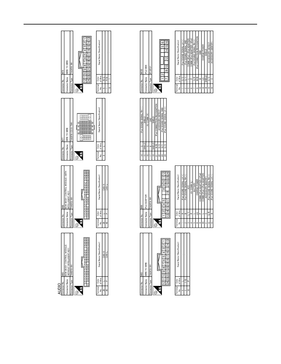
AV-60
< ECU DIAGNOSIS INFORMATION >
[AUDIO SYSTEM]
AUDIO UNIT
JCNWM2422GB
Revision: 2009 March
2009 Z12
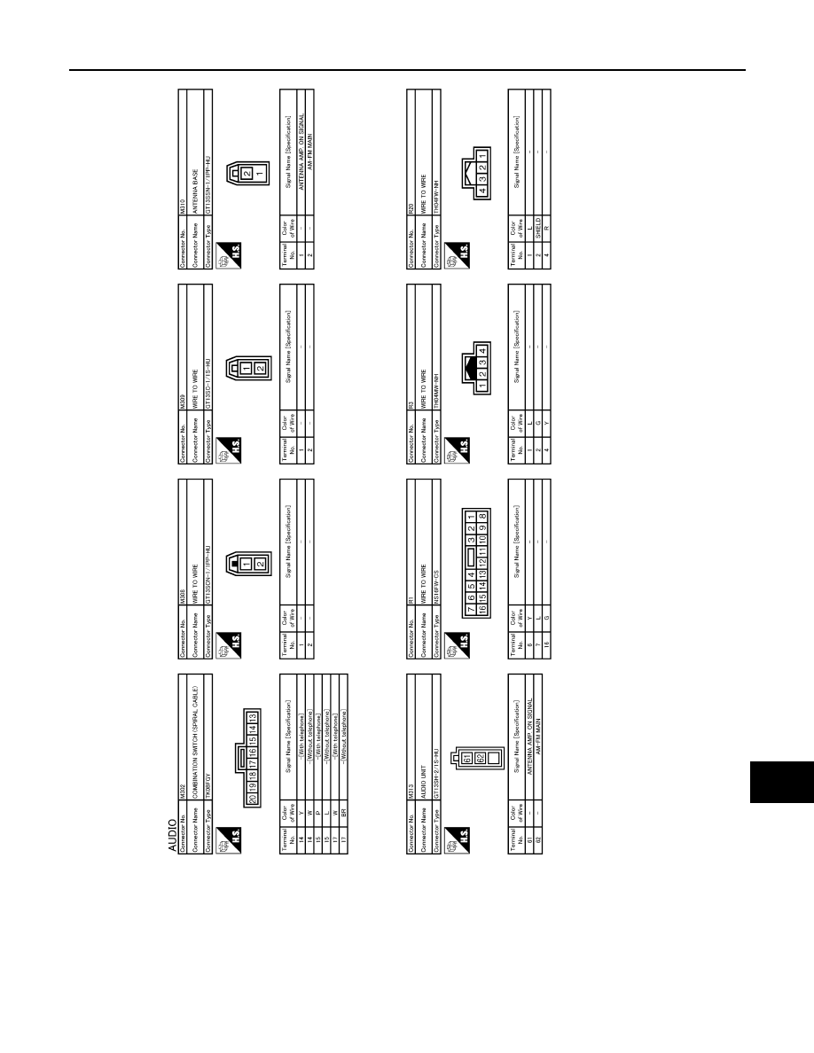
AV
AUDIO UNIT
AV-61
< ECU DIAGNOSIS INFORMATION >
[AUDIO SYSTEM]
C
D
E
F
G
H
I
J
K
L
M
B
A
O
P
JCNWM2423GB
Revision: 2009 March
2009 Z12
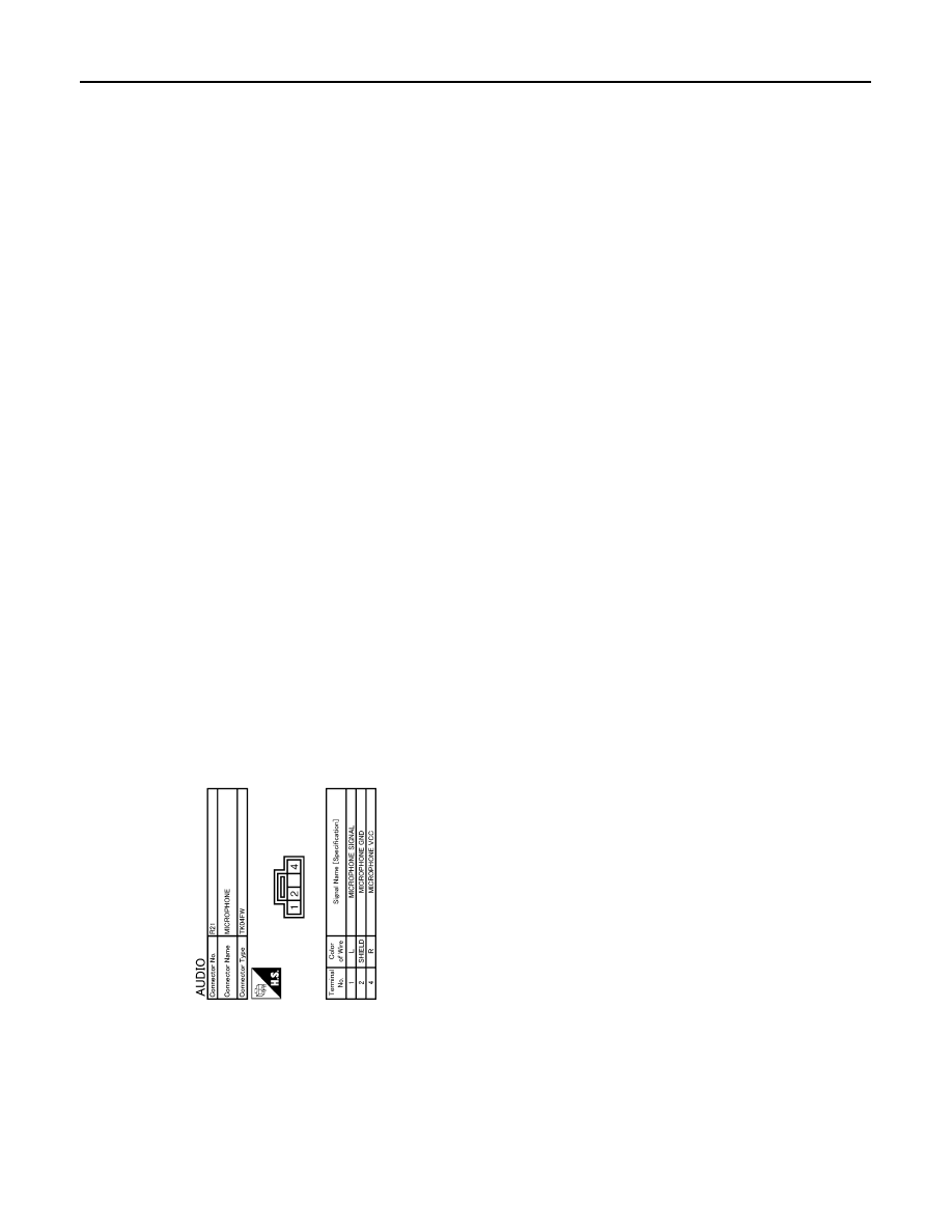
AV-62
< ECU DIAGNOSIS INFORMATION >
[AUDIO SYSTEM]
AUDIO UNIT
JCNWM2424GB
Revision: 2009 March
2009 Z12
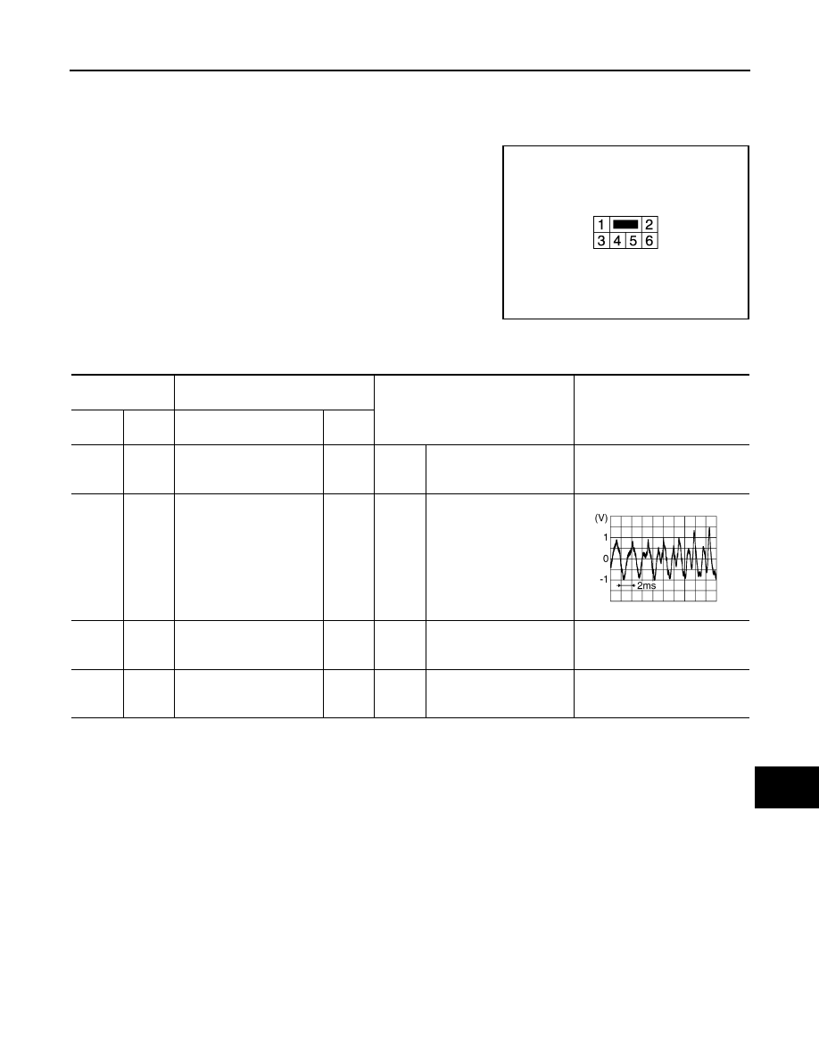
AV
WOOFER
AV-63
< ECU DIAGNOSIS INFORMATION >
[AUDIO SYSTEM]
C
D
E
F
G
H
I
J
K
L
M
B
A
O
P
WOOFER
Reference Value
INFOID:0000000004940259
TERMINAL LAYOUT
PHYSICAL VALUES
JPNIA1778ZZ
Terminal
(Wire color)
Description
Condition
Reference value
(Approx.)
+
–
Signal name
Input/
Output
1
(SB)
Ground
Battery power supply
Input
Ignition
switch
OFF
—
Battery voltage
2
(BR)
6
(R)
Sound signal woofer
Output
Ignition
switch
ON
Voice output
3
(B)
Ground
Ground
—
Ignition
switch
ON
—
0 V
4
(Y)
Ground
Woofer amp. ON signal
Input
Ignition
switch
ON
Voice output
12.0 V
SKIB3609E
Revision: 2009 March
2009 Z12

AV-64
< ECU DIAGNOSIS INFORMATION >
[AUDIO SYSTEM]
WOOFER
Wiring Diagram - AUDIO -
INFOID:0000000004940260
JCNWM2412GB
Revision: 2009 March
2009 Z12
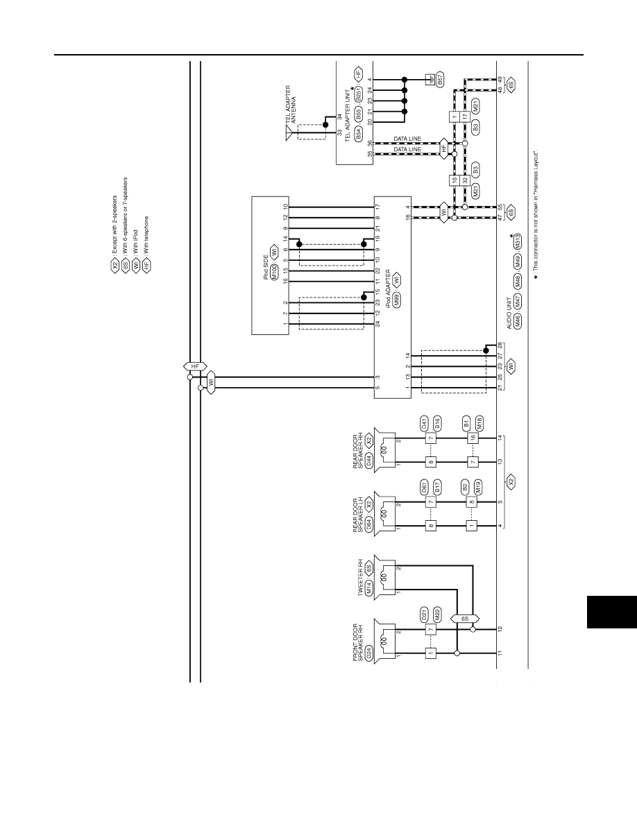
AV
WOOFER
AV-65
< ECU DIAGNOSIS INFORMATION >
[AUDIO SYSTEM]
C
D
E
F
G
H
I
J
K
L
M
B
A
O
P
JCNWM2413GB
Revision: 2009 March
2009 Z12

AV-66
< ECU DIAGNOSIS INFORMATION >
[AUDIO SYSTEM]
WOOFER
JCNWM2414GB
Revision: 2009 March
2009 Z12

AV
WOOFER
AV-67
< ECU DIAGNOSIS INFORMATION >
[AUDIO SYSTEM]
C
D
E
F
G
H
I
J
K
L
M
B
A
O
P
JCNWM2415GB
Revision: 2009 March
2009 Z12

AV-68
< ECU DIAGNOSIS INFORMATION >
[AUDIO SYSTEM]
WOOFER
JCNWM2416GB
Revision: 2009 March
2009 Z12

AV
WOOFER
AV-69
< ECU DIAGNOSIS INFORMATION >
[AUDIO SYSTEM]
C
D
E
F
G
H
I
J
K
L
M
B
A
O
P
JCNWM2417GB
Revision: 2009 March
2009 Z12
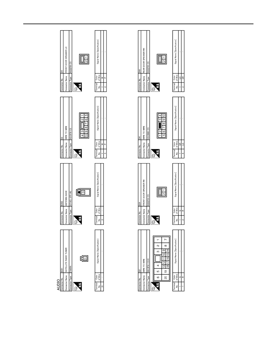
AV-70
< ECU DIAGNOSIS INFORMATION >
[AUDIO SYSTEM]
WOOFER
JCNWM2418GB
Revision: 2009 March
2009 Z12
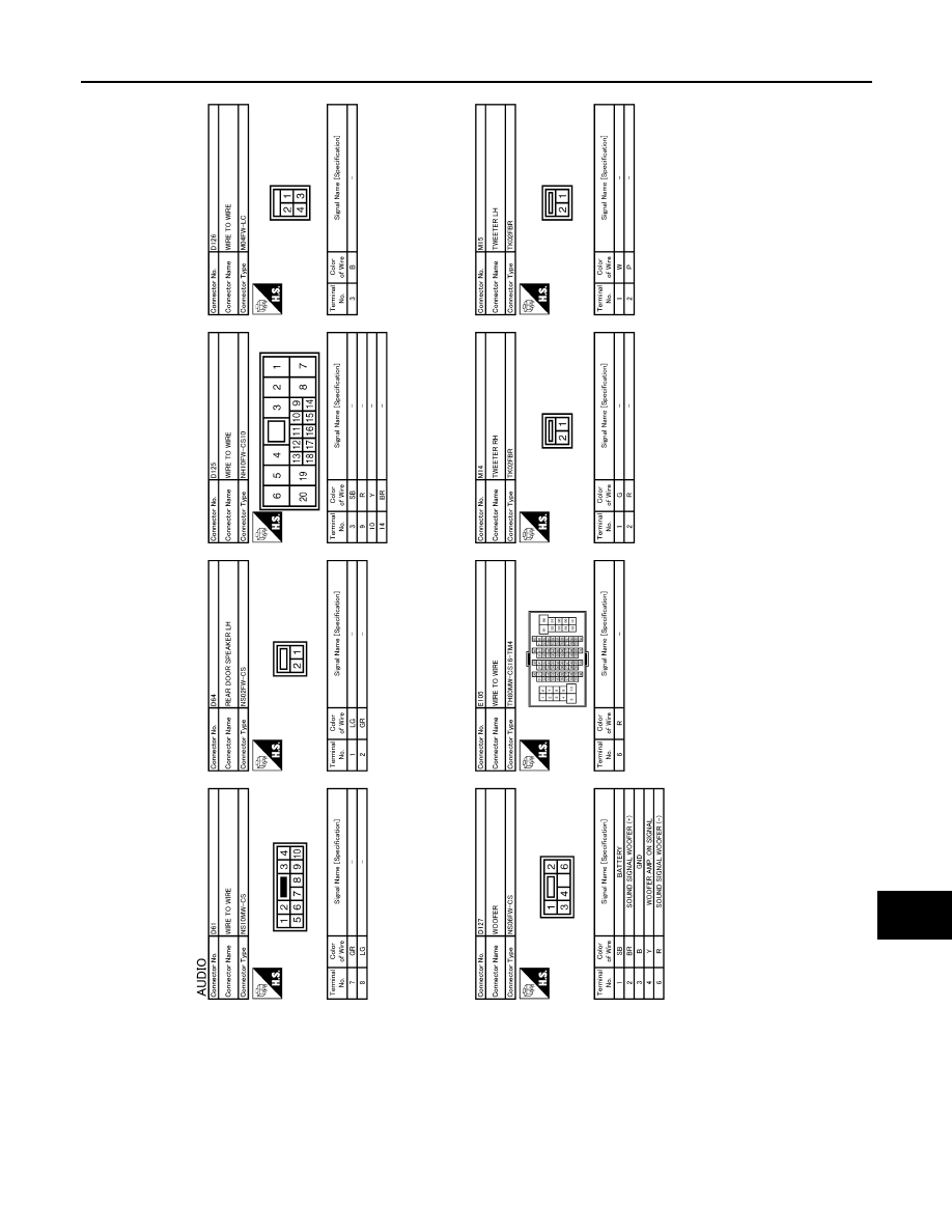
AV
WOOFER
AV-71
< ECU DIAGNOSIS INFORMATION >
[AUDIO SYSTEM]
C
D
E
F
G
H
I
J
K
L
M
B
A
O
P
JCNWM2419GB
Revision: 2009 March
2009 Z12

AV-72
< ECU DIAGNOSIS INFORMATION >
[AUDIO SYSTEM]
WOOFER
JCNWM2420GB
Revision: 2009 March
2009 Z12

AV
WOOFER
AV-73
< ECU DIAGNOSIS INFORMATION >
[AUDIO SYSTEM]
C
D
E
F
G
H
I
J
K
L
M
B
A
O
P
JCNWM2421GB
Revision: 2009 March
2009 Z12

AV-74
< ECU DIAGNOSIS INFORMATION >
[AUDIO SYSTEM]
WOOFER
JCNWM2422GB
Revision: 2009 March
2009 Z12

AV
WOOFER
AV-75
< ECU DIAGNOSIS INFORMATION >
[AUDIO SYSTEM]
C
D
E
F
G
H
I
J
K
L
M
B
A
O
P
JCNWM2423GB
Revision: 2009 March
2009 Z12

AV-76
< ECU DIAGNOSIS INFORMATION >
[AUDIO SYSTEM]
WOOFER
JCNWM2424GB
Revision: 2009 March
2009 Z12
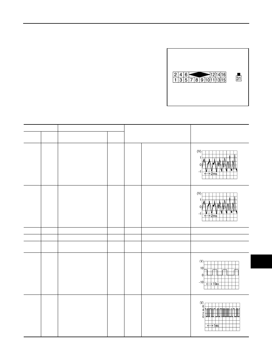
AV
SATELLITE RADIO TUNER
AV-77
< ECU DIAGNOSIS INFORMATION >
[AUDIO SYSTEM]
C
D
E
F
G
H
I
J
K
L
M
B
A
O
P
SATELLITE RADIO TUNER
Reference Value
INFOID:0000000004940261
TERMINAL LAYOUT
PHYSICAL VALUES
JPNIA1779ZZ
Terminal
Description
Condition
Reference value
(Approx.)
+
–
Signal name
Input/
Output
2
(R)
1
(G)
Satellite radio sound signal
LH
Output
Ignition
switch
ON
When satellite radio mode
is selected.
4
(B)
3
(W)
Satellite radio sound signal
RH
Output
Ignition
switch
ON
When satellite radio mode
is selected.
5
—
Shield
—
—
—
—
6
—
Shield
—
—
—
—
7
(P)
—
Control signal
—
—
—
—
8
(W)
Ground
Request signal
(SAT TO AUDIO)
Output
Ignition
switch
ON
When satellite radio mode
is selected.
9
(B)
Ground
Communication signal
(SAT
→
AUDIO)
Output
Ignition
switch
ON
When satellite radio mode
is selected.
SKIB3609E
SKIB3609E
SKIA9299J
PKIB5039J
Revision: 2009 March
2009 Z12

AV-78
< ECU DIAGNOSIS INFORMATION >
[AUDIO SYSTEM]
SATELLITE RADIO TUNER
10
(R)
Ground
Communication signal
(AUDIO
→
SAT)
Input
Ignition
switch
ON
When satellite radio mode
is selected.
11
(Y)
—
Request signal
(CHG TO AUDIO)
—
—
—
—
12
(SB)
Ground
Battery power supply
Input
Ignition
switch
OFF
—
Battery voltage
13
(W)
—
Source change
—
—
—
—
16
(V)
Ground
ACC power supply
Input
Ignition
switch
ACC
—
Battery voltage
31
—
Satellite radio antenna sig-
nal
Input
—
—
—
Terminal
Description
Condition
Reference value
(Approx.)
+
–
Signal name
Input/
Output
SKIA9301J
Revision: 2009 March
2009 Z12
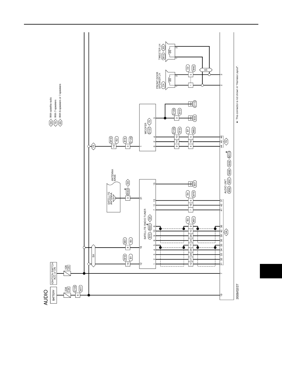
AV
SATELLITE RADIO TUNER
AV-79
< ECU DIAGNOSIS INFORMATION >
[AUDIO SYSTEM]
C
D
E
F
G
H
I
J
K
L
M
B
A
O
P
Wiring Diagram - AUDIO -
INFOID:0000000004940262
JCNWM2412GB
Revision: 2009 March
2009 Z12
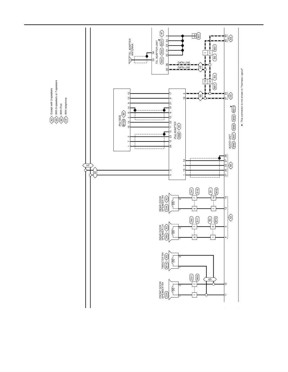
AV-80
< ECU DIAGNOSIS INFORMATION >
[AUDIO SYSTEM]
SATELLITE RADIO TUNER
JCNWM2413GB
Revision: 2009 March
2009 Z12
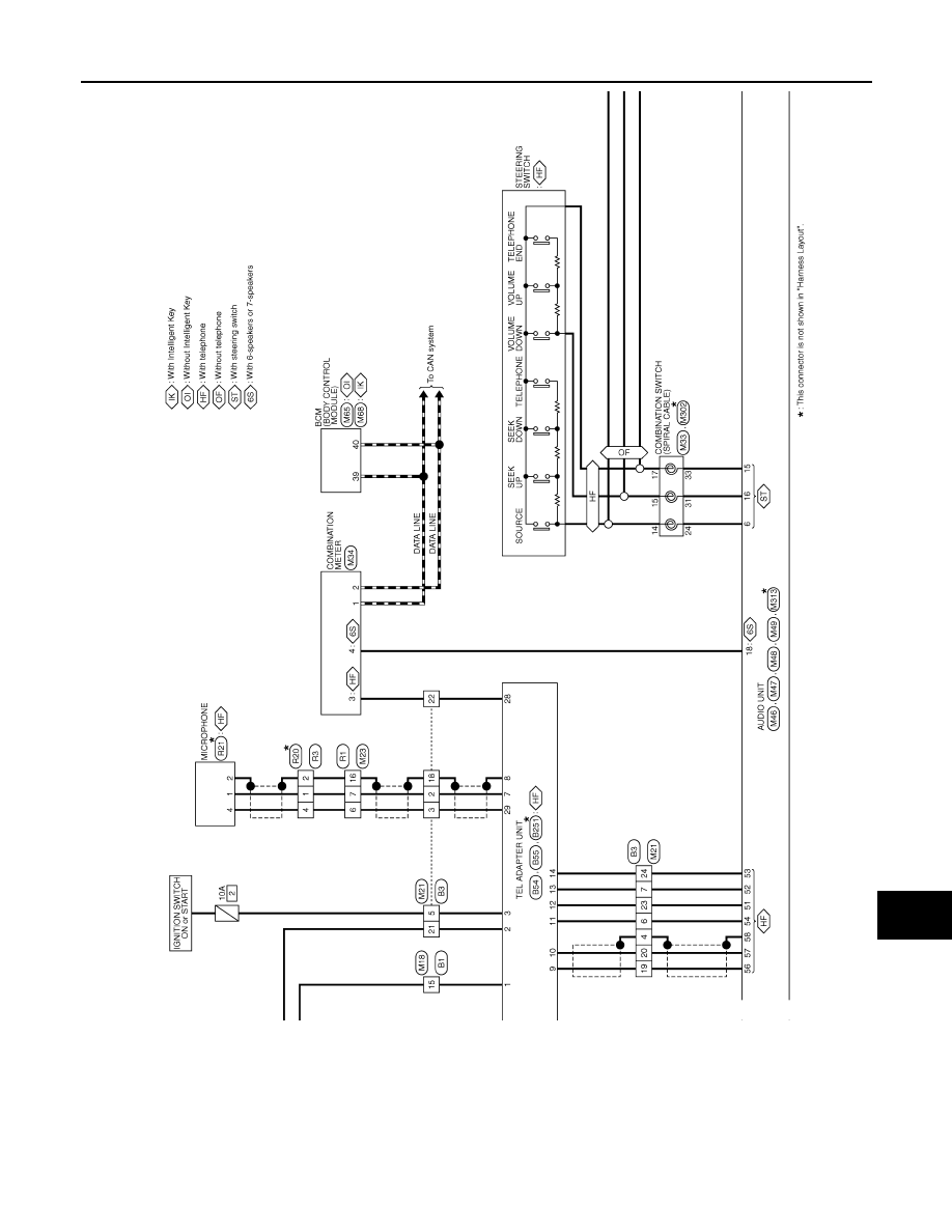
AV
SATELLITE RADIO TUNER
AV-81
< ECU DIAGNOSIS INFORMATION >
[AUDIO SYSTEM]
C
D
E
F
G
H
I
J
K
L
M
B
A
O
P
JCNWM2414GB
Revision: 2009 March
2009 Z12

AV-82
< ECU DIAGNOSIS INFORMATION >
[AUDIO SYSTEM]
SATELLITE RADIO TUNER
JCNWM2415GB
Revision: 2009 March
2009 Z12

AV
SATELLITE RADIO TUNER
AV-83
< ECU DIAGNOSIS INFORMATION >
[AUDIO SYSTEM]
C
D
E
F
G
H
I
J
K
L
M
B
A
O
P
JCNWM2416GB
Revision: 2009 March
2009 Z12
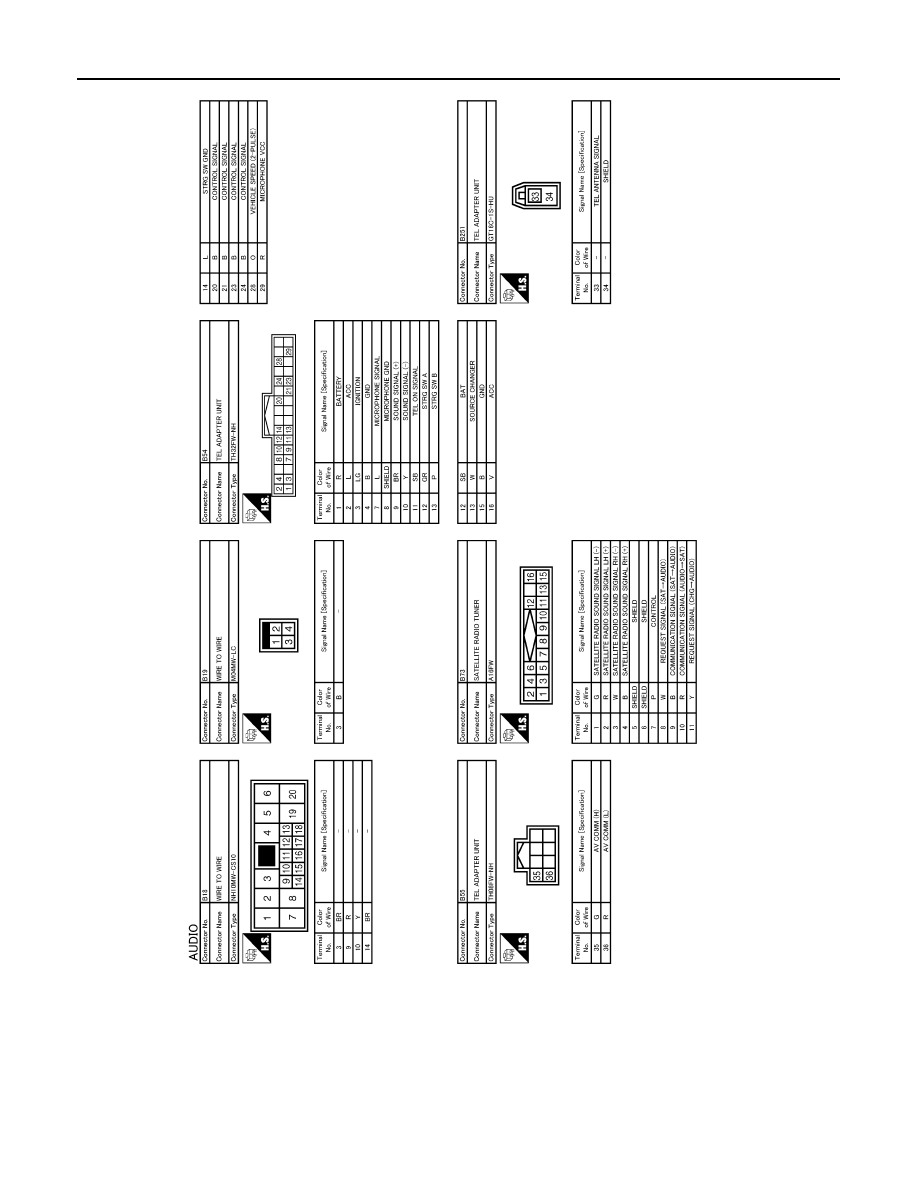
AV-84
< ECU DIAGNOSIS INFORMATION >
[AUDIO SYSTEM]
SATELLITE RADIO TUNER
JCNWM2417GB
Revision: 2009 March
2009 Z12
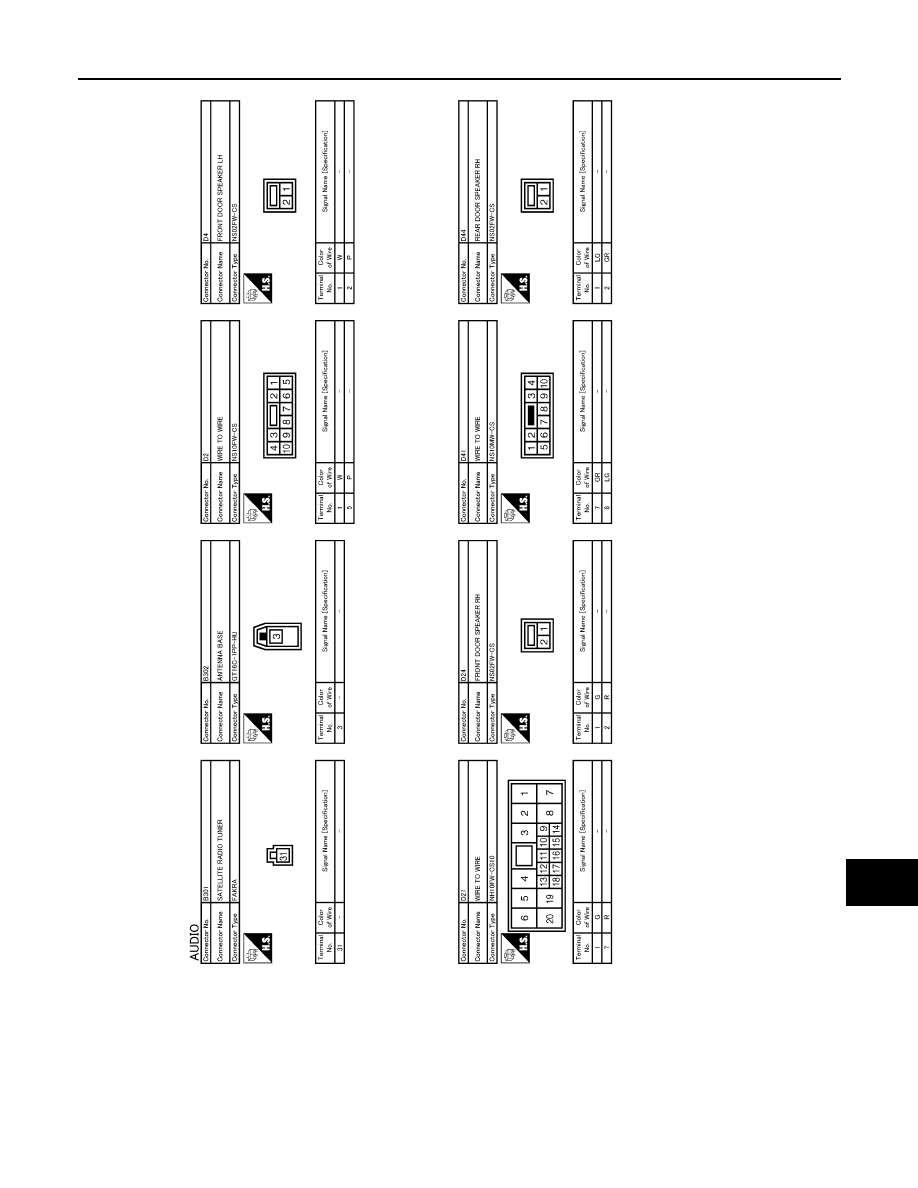
AV
SATELLITE RADIO TUNER
AV-85
< ECU DIAGNOSIS INFORMATION >
[AUDIO SYSTEM]
C
D
E
F
G
H
I
J
K
L
M
B
A
O
P
JCNWM2418GB
Revision: 2009 March
2009 Z12

AV-86
< ECU DIAGNOSIS INFORMATION >
[AUDIO SYSTEM]
SATELLITE RADIO TUNER
JCNWM2419GB
Revision: 2009 March
2009 Z12
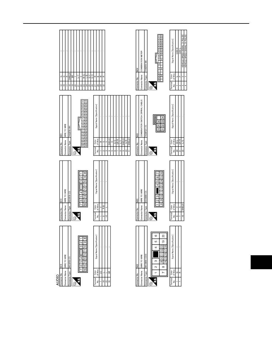
AV
SATELLITE RADIO TUNER
AV-87
< ECU DIAGNOSIS INFORMATION >
[AUDIO SYSTEM]
C
D
E
F
G
H
I
J
K
L
M
B
A
O
P
JCNWM2420GB
Revision: 2009 March
2009 Z12
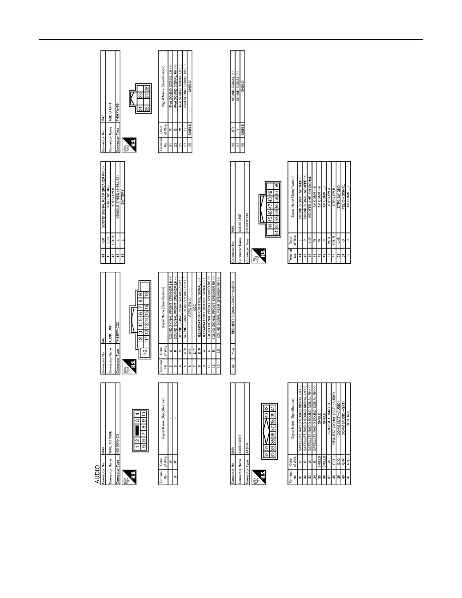
AV-88
< ECU DIAGNOSIS INFORMATION >
[AUDIO SYSTEM]
SATELLITE RADIO TUNER
JCNWM2421GB
Revision: 2009 March
2009 Z12

AV
SATELLITE RADIO TUNER
AV-89
< ECU DIAGNOSIS INFORMATION >
[AUDIO SYSTEM]
C
D
E
F
G
H
I
J
K
L
M
B
A
O
P
JCNWM2422GB
Revision: 2009 March
2009 Z12
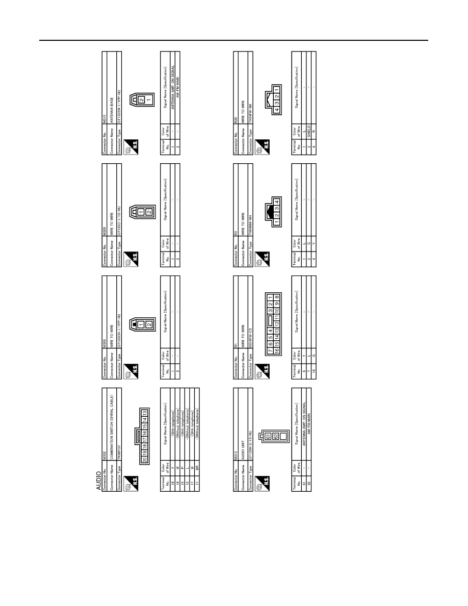
AV-90
< ECU DIAGNOSIS INFORMATION >
[AUDIO SYSTEM]
SATELLITE RADIO TUNER
JCNWM2423GB
Revision: 2009 March
2009 Z12

AV
SATELLITE RADIO TUNER
AV-91
< ECU DIAGNOSIS INFORMATION >
[AUDIO SYSTEM]
C
D
E
F
G
H
I
J
K
L
M
B
A
O
P
JCNWM2424GB
Revision: 2009 March
2009 Z12
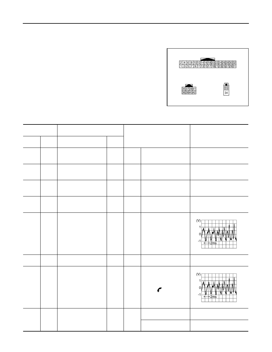
AV-92
< ECU DIAGNOSIS INFORMATION >
[AUDIO SYSTEM]
TEL ADAPTER UNIT
TEL ADAPTER UNIT
Reference Value
INFOID:0000000004940263
TERMINAL LAYOUT
PHYSICAL VALUES
JPNIA0011ZZ
Terminal
(Wire color)
Description
Condition
Reference value
(Approx.)
+
–
Signal name
Input/
Output
1
(R)
Ground
Battery power supply
Input
Ignition
switch
OFF
—
Battery voltage
2
(L)
Ground
ACC power supply
Input
Ignition
switch
ACC
—
Battery voltage
3
(LG)
Ground
Ignition signal
Input
Ignition
switch
ON
—
Battery voltage
4
(B)
Ground
Ground
—
Ignition
switch
ON
—
0 V
7
(L)
8
Microphone signal
Input
Ignition
switch
ON
Give a voice
8
—
Shield (microphone signal
ground)
—
—
—
—
9
(BR)
10
(Y)
Sound signal
(TEL voice, voice guid-
ance)
Output
Ignition
switch
ON
During voice guide output
with the
switch pressed.
11
(SB)
Ground
TEL ON signal
Output
Ignition
switch
ON
While using hands-free
phone system.
0 V
While not using hands-free
phone system.
5.0 V
SKIB3609E
SKIB3609E
Revision: 2009 March
2009 Z12

AV
TEL ADAPTER UNIT
AV-93
< ECU DIAGNOSIS INFORMATION >
[AUDIO SYSTEM]
C
D
E
F
G
H
I
J
K
L
M
B
A
O
P
12
(GR)
14
(L)
Steering switch signal A
Input
Ignition
switch
ON
Keep pressing
switch
0 V
Except for above
4.8 V
13
(P)
14
(L)
Steering switch signal B
Input
Ignition
switch
ON
Keep pressing
switch
0 V
Except for above.
4.8 V
14
(L)
Ground
Steering switch signal
ground
—
Ignition
switch
ON
—
0 V
20
(B)
Ground
Control signal
—
Ignition
switch
ON
—
0 V
21
(B)
Ground
Control signal
—
Ignition
switch
ON
—
0 V
23
(B)
Ground
Control signal
—
Ignition
switch
ON
—
0 V
24
(B)
Ground
Control signal
—
Ignition
switch
ON
—
0 V
28
(O)
Ground
Vehicle speed signal
(2-pulse)
Input
Ignition
switch
ON
When vehicle speed is ap-
prox. 40 km/h (25MPH)
NOTE:
The maximum voltage varies de-
pending on the specification
(destination unit).
29
(R)
Ground
Microphone power supply
Output
Ignition
switch
ON
—
5.0 V
33
—
TEL antenna signal
Input
—
Not connected to TEL an-
tenna connector.
5.0 V
34
—
Shield
—
—
—
—
35
(G)
—
AV communication signal
(H)
Input/
Output
—
—
—
36
(R)
—
AV communication signal
(L)
Input/
Output
—
—
—
Terminal
(Wire color)
Description
Condition
Reference value
(Approx.)
+
–
Signal name
Input/
Output
JSNIA0012GB
Revision: 2009 March
2009 Z12

AV-94
< ECU DIAGNOSIS INFORMATION >
[AUDIO SYSTEM]
TEL ADAPTER UNIT
Wiring Diagram - AUDIO -
INFOID:0000000004940264
JCNWM2412GB
Revision: 2009 March
2009 Z12

AV
TEL ADAPTER UNIT
AV-95
< ECU DIAGNOSIS INFORMATION >
[AUDIO SYSTEM]
C
D
E
F
G
H
I
J
K
L
M
B
A
O
P
JCNWM2413GB
Revision: 2009 March
2009 Z12
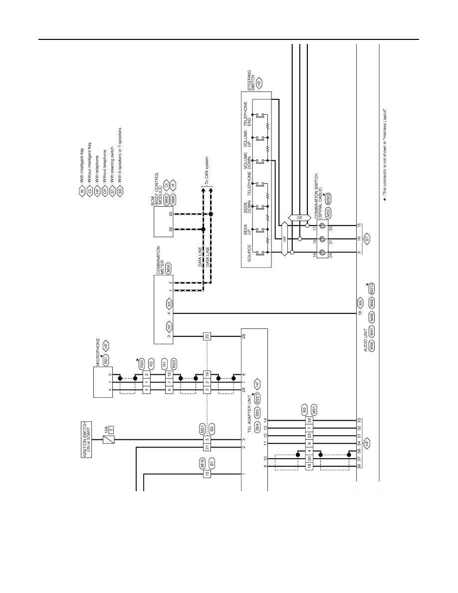
AV-96
< ECU DIAGNOSIS INFORMATION >
[AUDIO SYSTEM]
TEL ADAPTER UNIT
JCNWM2414GB
Revision: 2009 March
2009 Z12
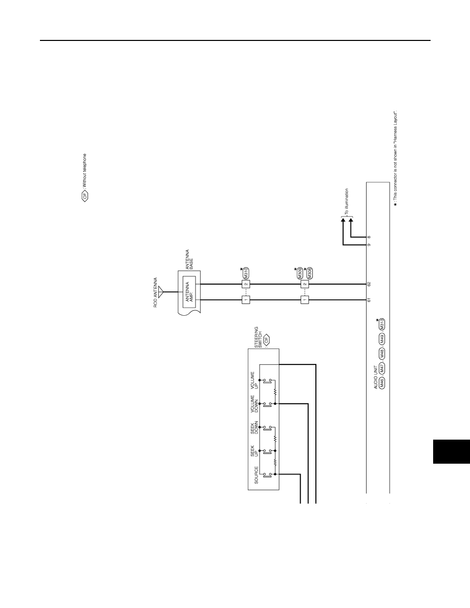
AV
TEL ADAPTER UNIT
AV-97
< ECU DIAGNOSIS INFORMATION >
[AUDIO SYSTEM]
C
D
E
F
G
H
I
J
K
L
M
B
A
O
P
JCNWM2415GB
Revision: 2009 March
2009 Z12

AV-98
< ECU DIAGNOSIS INFORMATION >
[AUDIO SYSTEM]
TEL ADAPTER UNIT
JCNWM2416GB
Revision: 2009 March
2009 Z12

AV
TEL ADAPTER UNIT
AV-99
< ECU DIAGNOSIS INFORMATION >
[AUDIO SYSTEM]
C
D
E
F
G
H
I
J
K
L
M
B
A
O
P
JCNWM2417GB
Revision: 2009 March
2009 Z12

AV-100
< ECU DIAGNOSIS INFORMATION >
[AUDIO SYSTEM]
TEL ADAPTER UNIT
JCNWM2418GB
Revision: 2009 March
2009 Z12

AV
TEL ADAPTER UNIT
AV-101
< ECU DIAGNOSIS INFORMATION >
[AUDIO SYSTEM]
C
D
E
F
G
H
I
J
K
L
M
B
A
O
P
JCNWM2419GB
Revision: 2009 March
2009 Z12
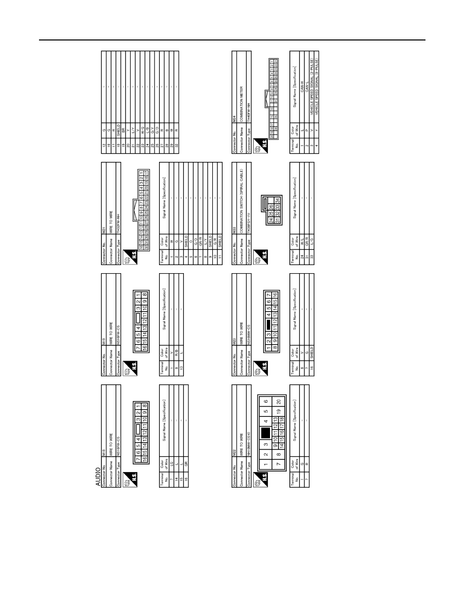
AV-102
< ECU DIAGNOSIS INFORMATION >
[AUDIO SYSTEM]
TEL ADAPTER UNIT
JCNWM2420GB
Revision: 2009 March
2009 Z12
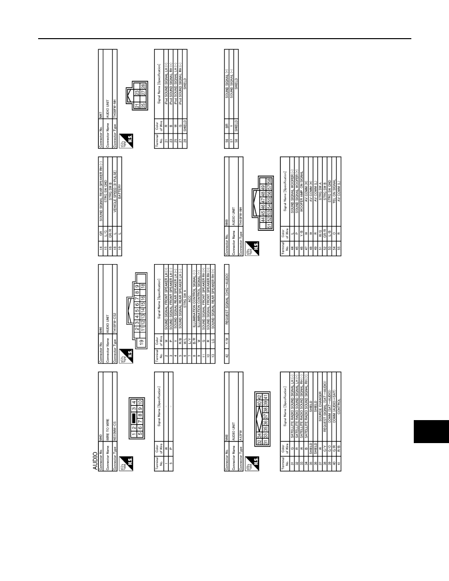
AV
TEL ADAPTER UNIT
AV-103
< ECU DIAGNOSIS INFORMATION >
[AUDIO SYSTEM]
C
D
E
F
G
H
I
J
K
L
M
B
A
O
P
JCNWM2421GB
Revision: 2009 March
2009 Z12

AV-104
< ECU DIAGNOSIS INFORMATION >
[AUDIO SYSTEM]
TEL ADAPTER UNIT
JCNWM2422GB
Revision: 2009 March
2009 Z12

AV
TEL ADAPTER UNIT
AV-105
< ECU DIAGNOSIS INFORMATION >
[AUDIO SYSTEM]
C
D
E
F
G
H
I
J
K
L
M
B
A
O
P
JCNWM2423GB
Revision: 2009 March
2009 Z12

AV-106
< ECU DIAGNOSIS INFORMATION >
[AUDIO SYSTEM]
TEL ADAPTER UNIT
JCNWM2424GB
Revision: 2009 March
2009 Z12
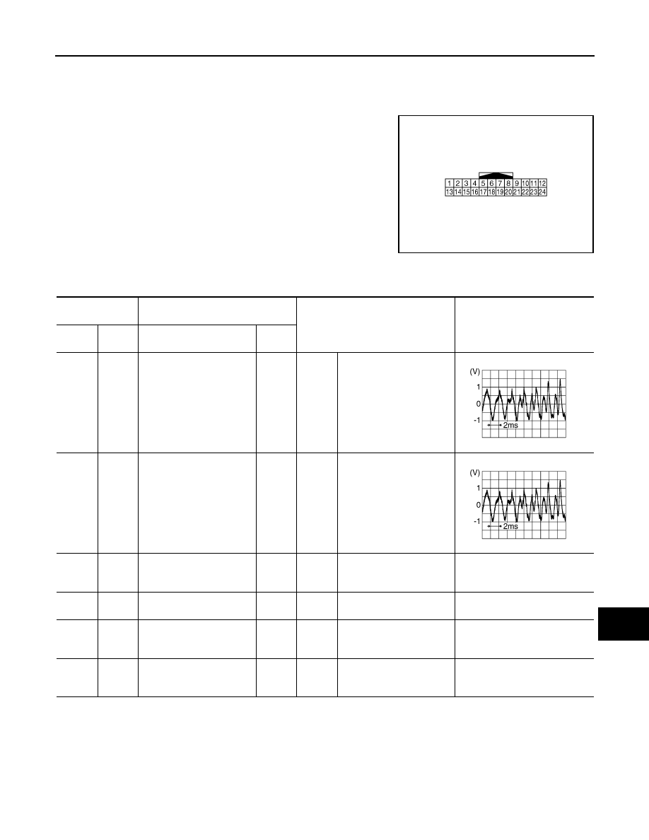
AV
IPOD ADAPTER
AV-107
< ECU DIAGNOSIS INFORMATION >
[AUDIO SYSTEM]
C
D
E
F
G
H
I
J
K
L
M
B
A
O
P
IPOD ADAPTER
Reference Value
INFOID:0000000004960354
TERMINAL LAYOUT
PHYSICAL VALUES
JSNIA0618ZZ
Terminal
(Wire color)
Description
Condition
Reference value
(Approx.)
+
–
Signal name
Input/
Output
1
(R)
13
(W)
iPod sound signal LH
Output
Ignition
switch
ON
When iPod mode is select-
ed.
2
(B)
14
(G)
iPod sound signal RH
Output
Ignition
switch
ON
When iPod mode is select-
ed.
3
(L/Y)
Ground
ACC power supply
Input
Ignition
switch
ACC
—
Battery voltage
4
(R)
—
AV communication signal
(L)
Input/
Output
—
—
—
5
(L)
Ground
Battery power supply
Input
Ignition
switch
OFF
—
Battery voltage
8
(LG)
Ground
iPod battery charge
Output
Ignition
switch
ON
Connected to iPod
®
12.0 V
SKIB3609E
SKIB3609E
Revision: 2009 March
2009 Z12
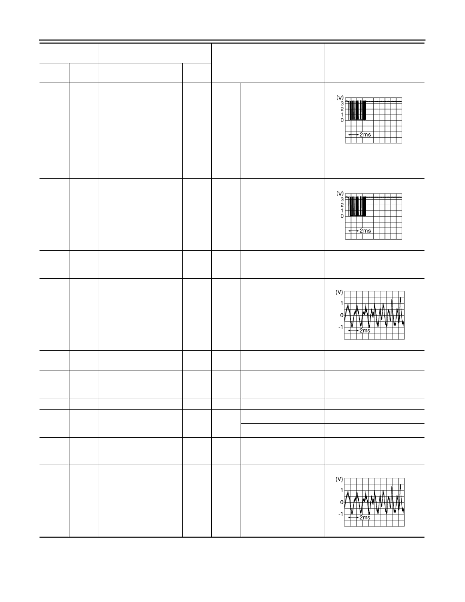
AV-108
< ECU DIAGNOSIS INFORMATION >
[AUDIO SYSTEM]
IPOD ADAPTER
9
(P)
Ground
Communication signal
(iPod adapter
→
iPod
®
)
Output
Ignition
switch
ON
The wave pattern is dis-
played just after iPod con-
nection.
NOTE:
After the wave pattern display,
the value continues Approx 3.3 V
10
(L)
Ground
Communication signal
(iPod
®
→
iPod adapter)
Input
Ignition
switch
ON
Connected to iPod
®
11
(O)
Ground
ACCESSORY-IDENTIFY
—
Ignition
switch
ON
Connected to iPod
®
0 V
12
(G/R)
23
(G/Y)
iPod sound signal RH
Input
Ignition
switch
ON
When iPod mode is select-
ed.
16
(G)
—
AV communication signal
(H)
Input/
Output
—
—
—
17
(B)
Ground
Ground
—
Ignition
switch
ON
—
0 V
19
—
Shield
—
—
—
—
21
(W/B)
Ground
iPod connection recogni-
tion signal
Input
Ignition
switch
ON
Not connected to iPod
®
4.0 V
Connected to iPod
®
0 V
22
(G/O)
Ground
ACCESSORY-DETECT
—
Ignition
switch
ON
Connected to iPod
®
0 V
24
(G/O)
23
(G/Y)
iPod sound signal LH
Input
Ignition
switch
ON
When iPod mode is select-
ed.
Terminal
(Wire color)
Description
Condition
Reference value
(Approx.)
+
–
Signal name
Input/
Output
JPNIA0462GB
JPNIA0462GB
SKIB3609E
SKIB3609E
Revision: 2009 March
2009 Z12

AV
IPOD ADAPTER
AV-109
< ECU DIAGNOSIS INFORMATION >
[AUDIO SYSTEM]
C
D
E
F
G
H
I
J
K
L
M
B
A
O
P
Wiring Diagram - AUDIO -
INFOID:0000000005175755
JCNWM2412GB
Revision: 2009 March
2009 Z12

AV-110
< ECU DIAGNOSIS INFORMATION >
[AUDIO SYSTEM]
IPOD ADAPTER
JCNWM2413GB
Revision: 2009 March
2009 Z12

AV
IPOD ADAPTER
AV-111
< ECU DIAGNOSIS INFORMATION >
[AUDIO SYSTEM]
C
D
E
F
G
H
I
J
K
L
M
B
A
O
P
JCNWM2414GB
Revision: 2009 March
2009 Z12
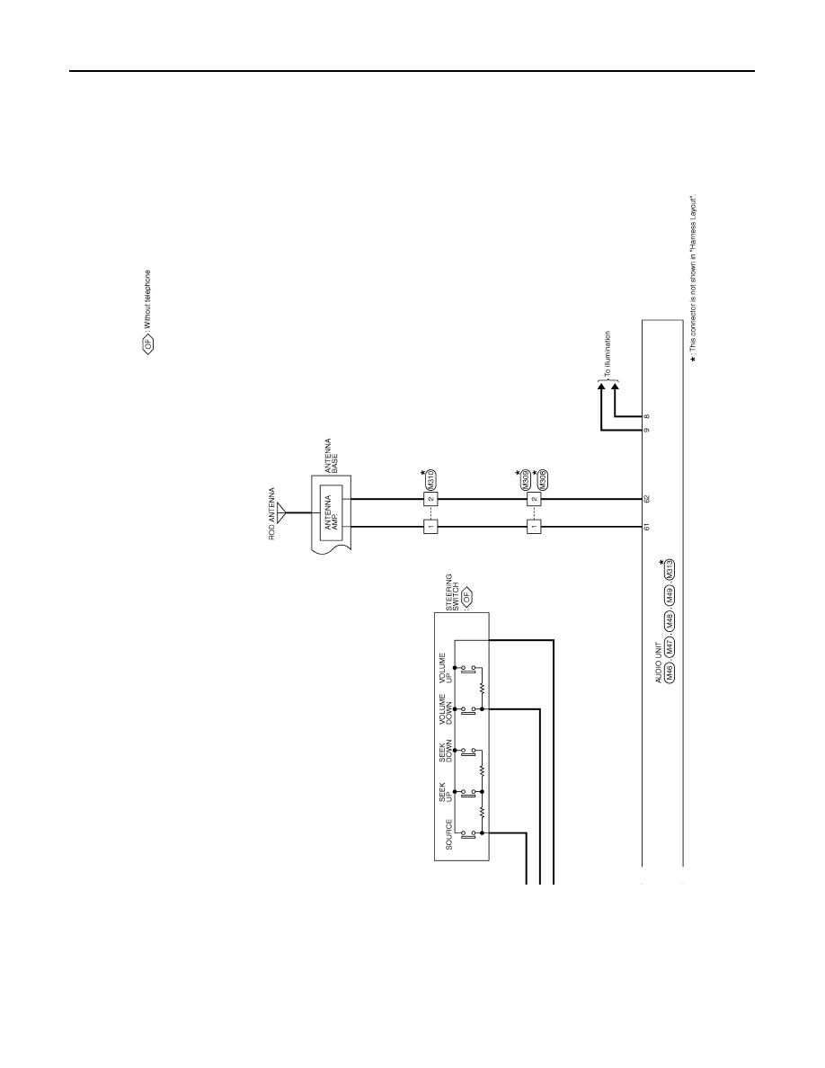
AV-112
< ECU DIAGNOSIS INFORMATION >
[AUDIO SYSTEM]
IPOD ADAPTER
JCNWM2415GB
Revision: 2009 March
2009 Z12
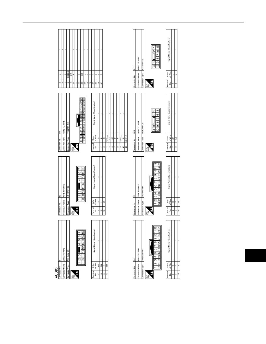
AV
IPOD ADAPTER
AV-113
< ECU DIAGNOSIS INFORMATION >
[AUDIO SYSTEM]
C
D
E
F
G
H
I
J
K
L
M
B
A
O
P
JCNWM2416GB
Revision: 2009 March
2009 Z12

AV-114
< ECU DIAGNOSIS INFORMATION >
[AUDIO SYSTEM]
IPOD ADAPTER
JCNWM2417GB
Revision: 2009 March
2009 Z12

AV
IPOD ADAPTER
AV-115
< ECU DIAGNOSIS INFORMATION >
[AUDIO SYSTEM]
C
D
E
F
G
H
I
J
K
L
M
B
A
O
P
JCNWM2418GB
Revision: 2009 March
2009 Z12
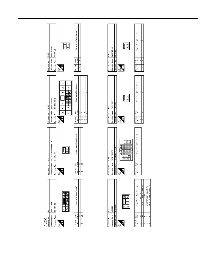
AV-116
< ECU DIAGNOSIS INFORMATION >
[AUDIO SYSTEM]
IPOD ADAPTER
JCNWM2419GB
Revision: 2009 March
2009 Z12

AV
IPOD ADAPTER
AV-117
< ECU DIAGNOSIS INFORMATION >
[AUDIO SYSTEM]
C
D
E
F
G
H
I
J
K
L
M
B
A
O
P
JCNWM2420GB
Revision: 2009 March
2009 Z12

AV-118
< ECU DIAGNOSIS INFORMATION >
[AUDIO SYSTEM]
IPOD ADAPTER
JCNWM2421GB
Revision: 2009 March
2009 Z12
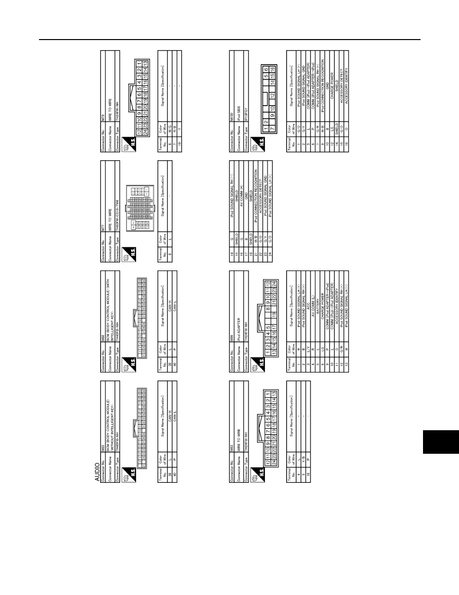
AV
IPOD ADAPTER
AV-119
< ECU DIAGNOSIS INFORMATION >
[AUDIO SYSTEM]
C
D
E
F
G
H
I
J
K
L
M
B
A
O
P
JCNWM2422GB
Revision: 2009 March
2009 Z12

AV-120
< ECU DIAGNOSIS INFORMATION >
[AUDIO SYSTEM]
IPOD ADAPTER
JCNWM2423GB
Revision: 2009 March
2009 Z12
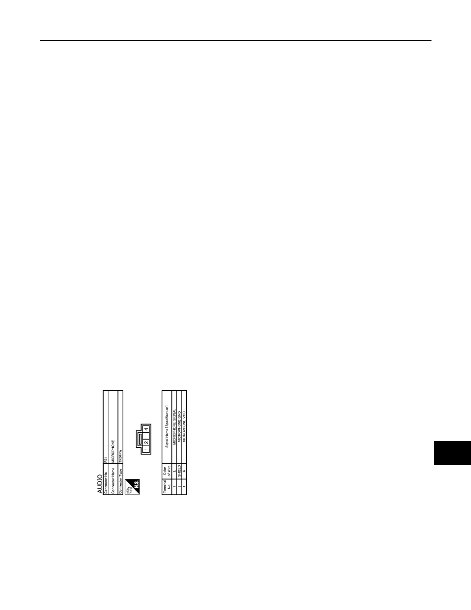
AV
IPOD ADAPTER
AV-121
< ECU DIAGNOSIS INFORMATION >
[AUDIO SYSTEM]
C
D
E
F
G
H
I
J
K
L
M
B
A
O
P
JCNWM2424GB
Revision: 2009 March
2009 Z12

AV-122
< SYMPTOM DIAGNOSIS >
[AUDIO SYSTEM]
AUDIO SYSTEM SYMPTOMS
SYMPTOM DIAGNOSIS
AUDIO SYSTEM SYMPTOMS
Symptom Table
INFOID:0000000004940265
AUDIO SYSTEM
RELATED TO iPod
®
Trouble Diagnosis Chart by Symptom
Connect another iPod
®
and check if the symptom is reproduced or not. If the symptom is reproduced, diag-
nose the vehicle. If no malfunction is detected, replace the iPod harness.
NOTE:
• It is unable to read a connection between iPod
®
and iPod harness.
• The iPod Touch and iPod Classic may not charge properly in some cases.
• As for iPod released concurrently with and after iPhone 3G (iPod Touch, iPod
Nano 4th generation, iPod
Classic 2nd generation, etc.) , 12 V charging circuit is deleted from iPod
®
.
Trouble diagnosis chart by symptom
Symptoms
Check items
Possible malfunction location / Action to take
Audio sound is not heard.
No sound from all speakers.
• Audio unit power supply and ground circuit. Refer to
"AUDIO UNIT : Diagnosis Procedure"
Sound is not heard from woofer.
• Change the speaker setting of the audio unit. Refer to
19, "MODELS WITH iPod® CONNECTION FUNCTION : Di-
agnosis Description"
.
• Sound signal woofer circuit
• Woofer amp. ON signal circuit. Refer to
.
Sound is not heard only from the
specific places.
Sound signal circuit of malfunctioning system.
Satellite radio is not received.
When “AUX” switch is pressed, it
change to satellite radio mode.
• Satellite radio sound signal circuit
• Satellite radio antenna
When “AUX” switch is pressed, it
does not change to satellite radio
mode.
• Satellite radio tuner power supply and ground circuit. Refer
AV-26, "SATELLITE RADIO TUNER : Diagnosis Proce-
• Request signal circuit. Refer to
• Communication circuit between audio unit and satellite radio
tuner. Refer to
Symptoms
Check items
Possible malfunction location / Action to take
There is no sound from the iP-
od
®
.
Other audio sounds are normal.
• iPod sound signal circuit between audio unit and iPod
adapter.
• iPod sound signal circuit between iPod
®
and iPod
adapter.
“iPod No connect” is displayed
when “iPod” switch is pressed.
• iPod battery charging is normal.
• iPod software and hardware version
are displayed when performing audio
unit self-diagnosis.
Communication circuit between iPod
®
and iPod adapter.
• iPod battery charging is normal.
• iPod software and hardware version
are not displayed when performing au-
dio unit self-diagnosis.
AV communication circuit between audio unit and iPod
adapter.
iPod battery charge does not work.
iPod adapter power supply and ground circuit. Refer to
AV-25, "iPod ADAPTER : Diagnosis Procedure"
iPod
®
cannot charge the bat-
tery.
Not chargeable even when connecting
other iPod
®
. Refer to above.
iPod battery charge circuit between iPod
®
and iPod
adapter.
Revision: 2009 March
2009 Z12
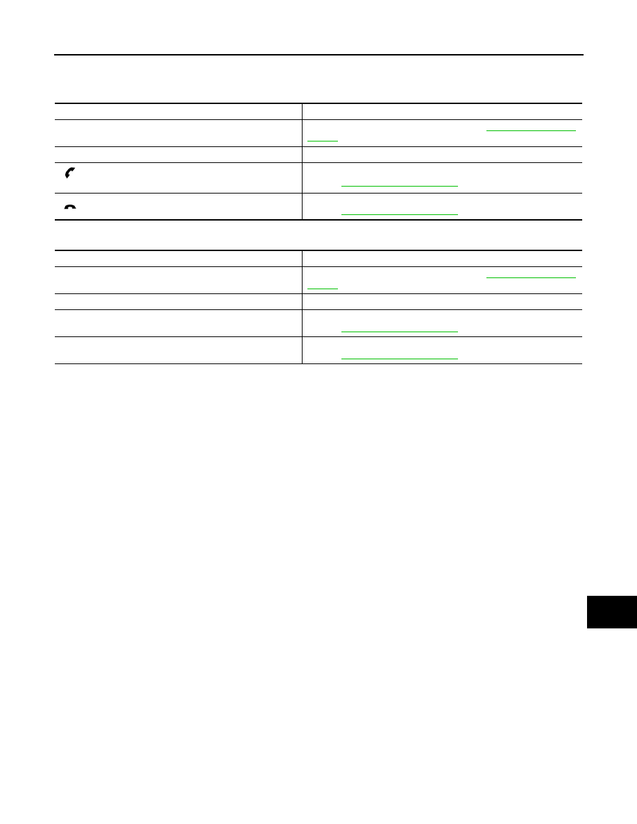
AV
AUDIO SYSTEM SYMPTOMS
AV-123
< SYMPTOM DIAGNOSIS >
[AUDIO SYSTEM]
C
D
E
F
G
H
I
J
K
L
M
B
A
O
P
iPod
®
is a trademark of Apple inc., registered in the U.S. and other countries.
RELATED TO STEERING SWITCH (MODELS WITH HANDS-FREE PHONE)
RELATED TO STEERING SWITCH (MODELS WITHOUT HANDS-FREE PHONE)
Symptoms
Possible malfunction location / Action to take
All steering switches are not operated.
Steering switch signal ground circuit. Refer to
Only specified switch cannot be operated.
Steering switch
“
”, “SEEK UP”, “SEEK DOWN” and “SOURCE” switches
are not operated.
Steering switch signal A circuit (steering switch to audio unit).
Refer to
“
”, “VOL UP” and “VOL DOWN” switches are not operated.
Steering switch signal B circuit (steering switch to audio unit).
Refer to
Symptoms
Possible malfunction location / Action to take
All steering switches are not operated.
Steering switch signal ground circuit. Refer to
Only specified switch cannot be operated.
Steering switch
“SEEK UP”, “SEEK DOWN” and “SOURCE” switches are not
operated.
Steering switch signal A circuit.
Refer to
“VOL UP” and “VOL DOWN” switches are not operated.
Steering switch signal B circuit.
Refer to
Revision: 2009 March
2009 Z12
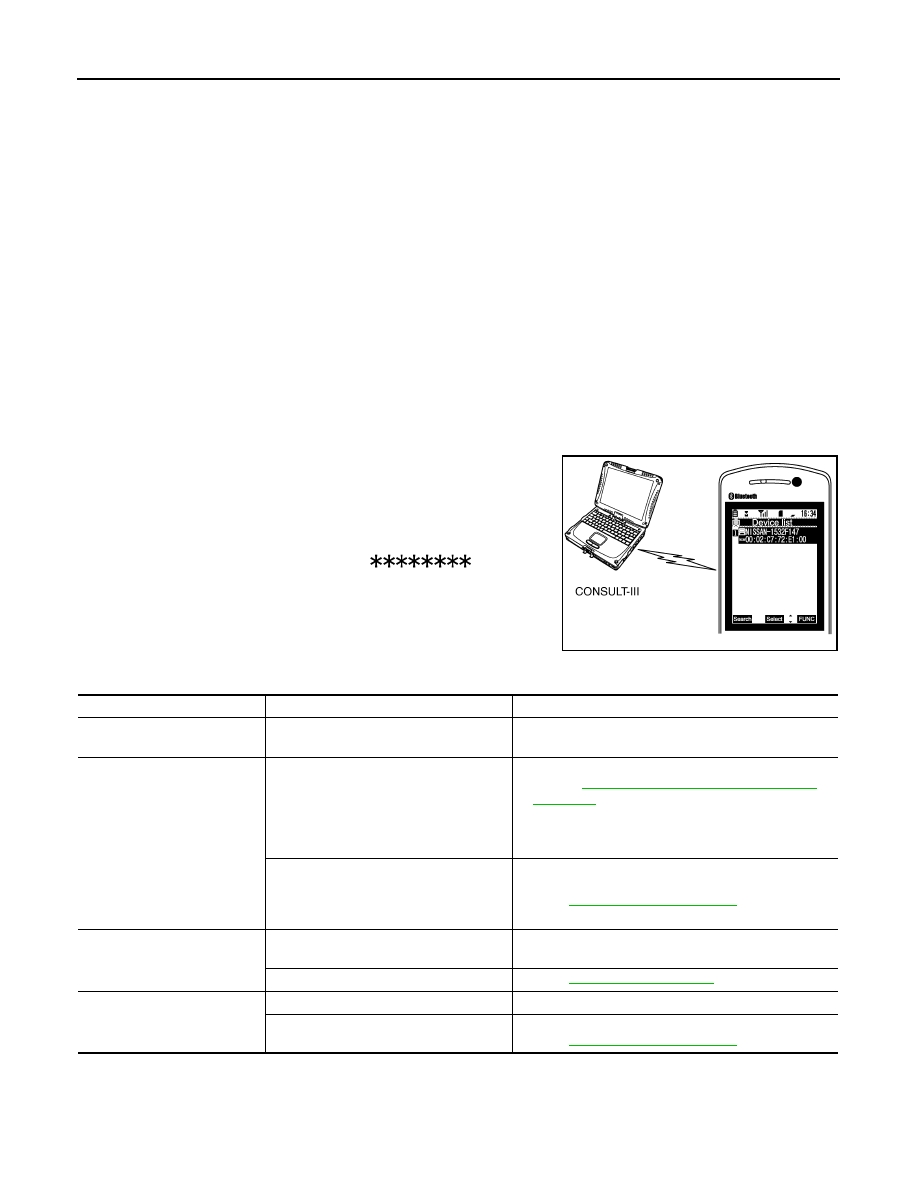
AV-124
< SYMPTOM DIAGNOSIS >
[AUDIO SYSTEM]
HANDS-FREE PHONE SYMPTOMS
HANDS-FREE PHONE SYMPTOMS
Symptom Table
INFOID:0000000004940266
RELATED TO HANDS-FREE PHONE
• Check that the cellular phone is corresponding type (Bluetooth
™
enabled) when the hands-free related mal-
function vehicle is in service before performing a diagnosis.
• There is a case that malfunction occurs due to the version change of the phone type, etc. even though it is a
corresponding type. Therefore, confirm it by changing the cellular phone to another corresponding type
phone, and check that it operates normally. It is necessary to distinguish whether the cause is the vehicle or
cellular phone. Check to ensure the customer's phone is supported by checking the phone compatibility for
the hands-free system.
Simple Check for Bluetooth
™
Communication
If cellular phone and TEL adapter unit cannot be connected with Bluetooth
™
communication, following proce-
dure allows the technician to judge which device has malfunction.
1.
Turn on a cellular phone, not connecting Bluetooth
™
communication.
2.
Start CONSULT-III, then start Windows
®
.
3.
Set CONSULT-III near a cellular phone.
4.
When operated Bluetooth
™
registration by cellular phone, check
if CONSULT-III
*
would be displayed on the device name.
(If other Bluetooth
™
device is located near cellular phone, a
name of the device would be displayed also.)
NOTE:
*:Displayed device name is “NISSAN-
”.
• If no device name is displayed, cellular phone is malfunction.
Repair the cellular phone first, then perform diagnosis.
• If CONSULT-III is displayed on device name, cellular phone is nor-
mal. Perform diagnosis as per the following table.
Trouble Diagnosis Chart by Symptom
RELATED TO STEERING SWITCH
JPNIA0441GB
Symptoms
Check items
Possible malfunction location/Action to take
Does not recognize cellular
phone connection.
Repeat the registration of cellular phone.
TEL adapter unit
Hands-free phone cannot be
established.
Both the reception and the speech cannot
be performed.
• TEL adapter unit power supply and ground circuit.
Refer to
AV-26, "TEL ADAPTER UNIT : Diagnosis
.
• Control signal circuit
• AV communication circuit between audio unit and TEL
adapter unit.
• Both the reception and the speech can-
not be performed.
• Audio can be operated by steering
switch.
TEL ON signal circuit.
Refer to
The other party's voice cannot
be heard by hands-free phone.
Audio system sound is normal.
Sound signal (telephone voice, telephone guidance) cir-
cuit
Audio system sound does not sound.
Refer to
Originating sound is not heard
by the other party with hands-
free phone communication.
Sound operation function is normal.
TEL adapter unit
Sound operation function does not work.
Microphone signal circuit.
Refer to
Revision: 2009 March
2009 Z12

AV
HANDS-FREE PHONE SYMPTOMS
AV-125
< SYMPTOM DIAGNOSIS >
[AUDIO SYSTEM]
C
D
E
F
G
H
I
J
K
L
M
B
A
O
P
Symptoms
Possible malfunction location / Action to take
All steering switches are not operated.
Steering switch signal ground circuit (steering switch to audio unit). Re-
fer to
.
Only specified switch cannot be operated.
Steering switch
“
”,“SEEK UP”, “SEEK DOWN” and “SOURCE” switches
are not operated.
Steering switch signal A circuit (steering switch to audio unit).
Refer to
“
”, “VOL UP” and “VOL DOWN” switches are not operated.
Steering switch signal B circuit (steering switch to audio unit).
Refer to
“
” switch is not operated.
Steering switch signal A circuit (audio unit to TEL adapter unit).
Refer to
“
” switch is not operated.
Steering switch signal B circuit (audio unit to TEL adapter unit).
Refer to
“
” and “
” switches are not operated.
Steering switch signal ground circuit (audio unit to TEL adapter unit).
Refer to
Revision: 2009 March
2009 Z12

AV-126
< SYMPTOM DIAGNOSIS >
[AUDIO SYSTEM]
NORMAL OPERATING CONDITION
NORMAL OPERATING CONDITION
Description
INFOID:0000000004940267
RELATED TO AUDIO
• The majority of the audio malfunctions are the result of outside causes (bad CD, electromagnetic interfer-
ence, etc.). Check the symptoms below to diagnose the malfunction.
• The vehicle itself can be a source of noise if noise prevention parts or electrical equipment is malfunctioning.
Check that noise is caused and/or changed by engine speed, ignition switch turned to each position, and
operation of each piece of electrical equipment. Then determine the cause.
NOTE:
• CD-R is not guaranteed to play because they can contain compressed audio (MP3, WMA) or could be incor-
rectly mastered by the customer on a computer.
• Check that the CDs carry the Compact Disc Logo. If not, the disc is not mastered to the red book Compact
Disc Standard and may not play.
Noise resulting from variations in field strength, such as fading noise and multi-path noise, or external noise from trains and other
sources, is not a malfunction.
NOTE:
• Fading noise: This noise occurs because of variations in the field strength in a narrow range due to mountains or buildings blocking
the signal.
• Multi-path noise: This noise results from a time difference between the broadcast waves directly from the station arriving at the
antenna and the waves reflected by mountains or buildings.
RELATED TO TELEPHONE
Symptoms
Cause and Counter measure
Cannot play
Check that the disc was inserted correctly.
Check that the disc is scratched or dirty.
Check if there is condensation inside the player. If there is, wait until the condensation is gone
(about 1 hour) before using the player.
If there is a temperature increase error, the CD player will play correctly after it returns to the nor-
mal temperature.
Files with extensions other than “.MP3”, “.WMA”, “.mp3”, or “.wma” cannot be played. In addition,
the character codes and number of characters for folder names and file names should be in com-
pliance with the specifications.
Check if the disc or the file is generated in an irregular format. This may occur depending on the
variation or the setting of MP3/WMA writing applications or other text editing applications.
Check if the finalization process, such as session close and disc close, is done for the disc.
Check if the disc is protected by copyright.
Poor sound quality
Check if the disc is scratched or dirty.
Bit rate may be too low.
It takes a relatively long time before
the music starts playing.
If there are many folder or file levels on the MP3/WMA CD, or if it is a multisession disc, some
time may be required before the music starts playing.
Music cuts off or skips
The writing software and hardware combination might not match, or the writing speed, writing
depth, writing width, etc., might not match the specifications. Try using the slowest writing speed.
Skipping with high bit rate files
Skipping may occur with large quantities of data, such as for high bit rate data.
Move immediately to the next song
when playing.
When a non-MP3/WMA file has been given an extension of “.MP3”, “.WMA”, “.mp3” or “.wma”, or
when play is prohibited by copyright protection, there will be approximately 5 seconds of no sound
and then the player will skip to the next song.
The songs do not play back in the
desired order.
The playback order is the order in which the files were written by the writing software. Therefore,
the files might not play in the desired order.
Revision: 2009 March
2009 Z12

AV
NORMAL OPERATING CONDITION
AV-127
< SYMPTOM DIAGNOSIS >
[AUDIO SYSTEM]
C
D
E
F
G
H
I
J
K
L
M
B
A
O
P
Symptoms
Cause and Counter measure
System fails to interpret the com-
mand correctly.
1. Ensure that the command format is valid.
2. Ensure that the command is spoken after the tone.
3. Speak clearly without pausing between words and at a level appropriate to the ambient noise
level in the vehicle.
4. Ensure that the ambient noise level is not excessive (for example, windows open or defroster
on).
NOTE:
If it is too noisy to use the phone, it is likely that the voice commands will not be recognized.
5. If more than one command was said at a time, try saying the commands separately.
6. If the system consistently fails to recognize commands, the voice training procedure should be
carried out to improve the recognition response for the speaker.
Refer to
AV-23, "Diagnosis Description"
.
The system consistently selects
the wrong entry from the phone
book.
1. Ensure that the phone book entry name requested matches what was originally stored. This
can be confirmed by using the “List Names” command.
2. Replace one of the names being confused with a new name.
Revision: 2009 March
2009 Z12

AV-128
< PRECAUTION >
[AUDIO SYSTEM]
PRECAUTIONS
PRECAUTION
PRECAUTIONS
Precaution for Supplemental Restraint System (SRS) "AIR BAG" and "SEAT BELT
PRE-TENSIONER"
INFOID:0000000005167696
The Supplemental Restraint System such as “AIR BAG” and “SEAT BELT PRE-TENSIONER”, used along
with a front seat belt, helps to reduce the risk or severity of injury to the driver and front passenger for certain
types of collision. This system includes seat belt switch inputs and dual stage front air bag modules. The SRS
system uses the seat belt switches to determine the front air bag deployment, and may only deploy one front
air bag, depending on the severity of a collision and whether the front occupants are belted or unbelted.
Information necessary to service the system safely is included in the “SRS AIR BAG” and “SEAT BELT” of this
Service Manual.
WARNING:
• To avoid rendering the SRS inoperative, which could increase the risk of personal injury or death in
the event of a collision which would result in air bag inflation, all maintenance must be performed by
an authorized NISSAN/INFINITI dealer.
• Improper maintenance, including incorrect removal and installation of the SRS, can lead to personal
injury caused by unintentional activation of the system. For removal of Spiral Cable and Air Bag
Module, see the “SRS AIR BAG”.
• Do not use electrical test equipment on any circuit related to the SRS unless instructed to in this
Service Manual. SRS wiring harnesses can be identified by yellow and/or orange harnesses or har-
ness connectors.
PRECAUTIONS WHEN USING POWER TOOLS (AIR OR ELECTRIC) AND HAMMERS
WARNING:
• When working near the Air Bag Diagnosis Sensor Unit or other Air Bag System sensors with the
ignition ON or engine running, DO NOT use air or electric power tools or strike near the sensor(s)
with a hammer. Heavy vibration could activate the sensor(s) and deploy the air bag(s), possibly
causing serious injury.
• When using air or electric power tools or hammers, always switch the ignition OFF, disconnect the
battery, and wait at least 3 minutes before performing any service.
Revision: 2009 March
2009 Z12
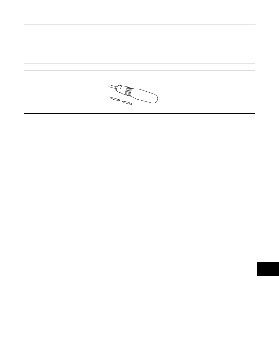
AV
PREPARATION
AV-129
< PREPARATION >
[AUDIO SYSTEM]
C
D
E
F
G
H
I
J
K
L
M
B
A
O
P
PREPARATION
PREPARATION
Commercial Service Tools
INFOID:0000000004940270
Tool name
Description
Power tool
Loosening bolts and nuts
PBIC0191E
Revision: 2009 March
2009 Z12
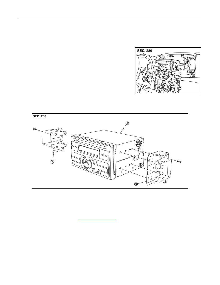
AV-130
< REMOVAL AND INSTALLATION >
[AUDIO SYSTEM]
AUDIO UNIT
REMOVAL AND INSTALLATION
AUDIO UNIT
Exploded View
INFOID:0000000004940271
REMOVAL
DISASSEMBLY
Removal and Installation
INFOID:0000000004940272
REMOVAL
1.
Remove cluster lid C. Refer to
2.
Remove audio unit screws, then disconnect audio unit connector and remove audio unit.
3.
Remove bracket screws to remove audio unit.
INSTALLATION
Install in the reverse order of removal.
JPNIA1638ZZ
1.
Audio unit
JPNIA1639ZZ
1.
Audio unit
2.
Bracket LH
3.
Bracket RH
Revision: 2009 March
2009 Z12

AV
FRONT DOOR SPEAKER
AV-131
< REMOVAL AND INSTALLATION >
[AUDIO SYSTEM]
C
D
E
F
G
H
I
J
K
L
M
B
A
O
P
FRONT DOOR SPEAKER
Exploded View
INFOID:0000000004940273
Removal and Installation
INFOID:0000000004940274
REMOVAL
1.
Remove front door finisher. Refer to
.
2.
Remove front door speaker screws, then disconnect front door speaker connector and remove front door
speaker.
INSTALLATION
Install in the reverse order of removal.
JPNIA1640ZZ
1.
Front door speaker
Revision: 2009 March
2009 Z12
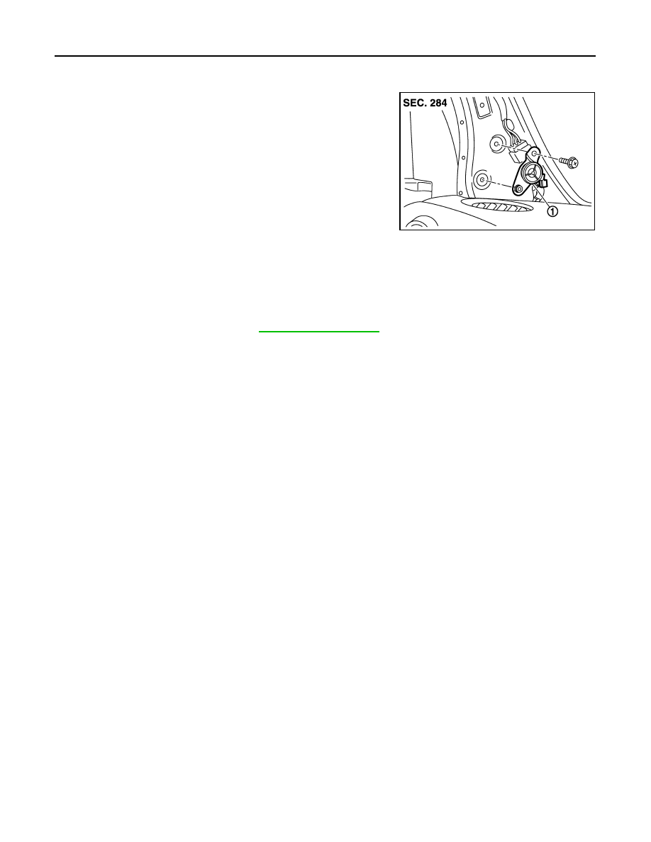
AV-132
< REMOVAL AND INSTALLATION >
[AUDIO SYSTEM]
TWEETER
TWEETER
Exploded View
INFOID:0000000004940275
Removal and Installation
INFOID:0000000004940276
REMOVAL
1.
Remove front pillar garnish. Refer to
.
2.
Remove tweeter screw and clip, then disconnect tweeter connector and remove tweeter.
INSTALLATION
Install in the reverse order of removal.
JPNIA1696ZZ
1.
Tweeter
Revision: 2009 March
2009 Z12
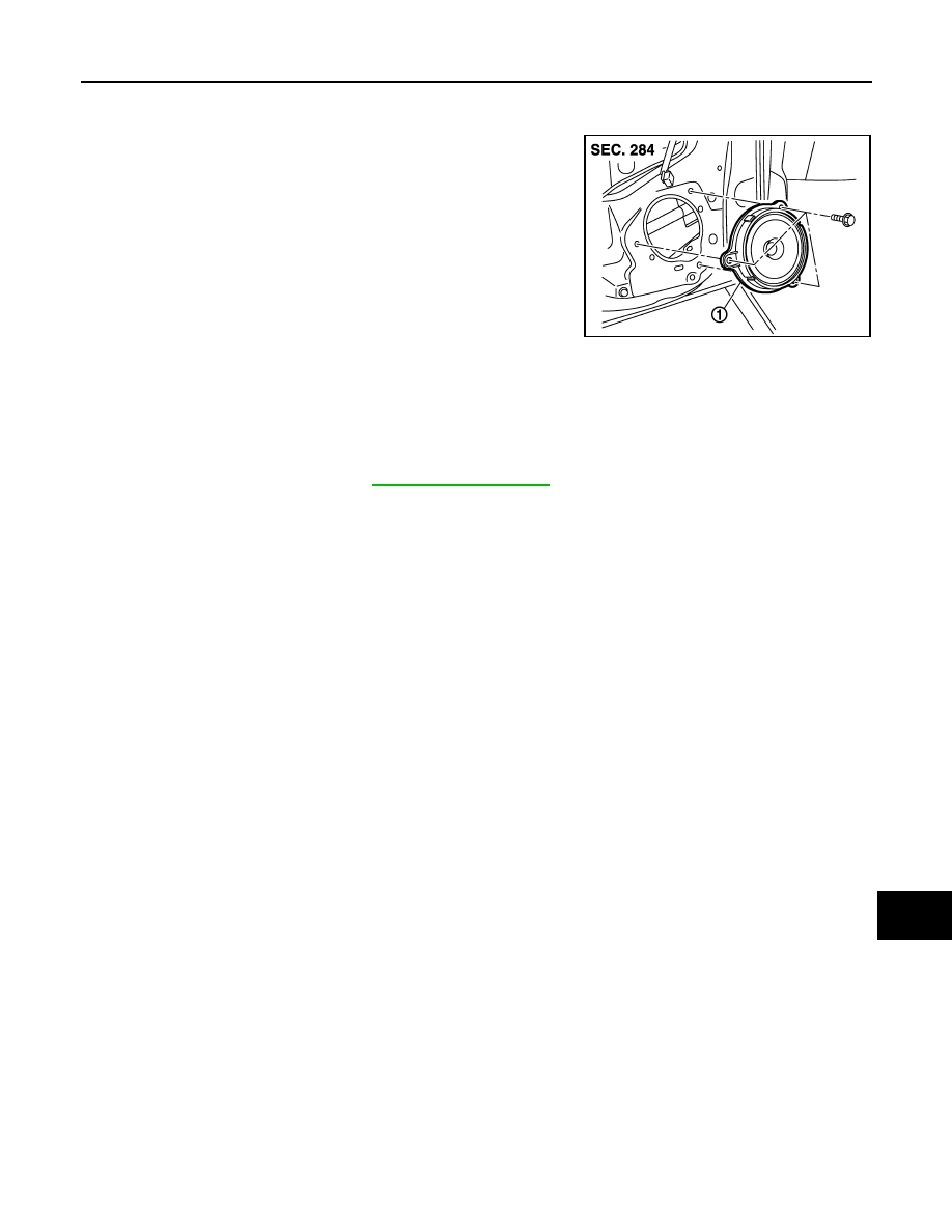
AV
REAR DOOR SPEAKER
AV-133
< REMOVAL AND INSTALLATION >
[AUDIO SYSTEM]
C
D
E
F
G
H
I
J
K
L
M
B
A
O
P
REAR DOOR SPEAKER
Exploded View
INFOID:0000000004940277
Removal and Installation
INFOID:0000000004940278
REMOVAL
1.
Remove rear door finisher. Refer to
.
2.
Remove rear door speaker screws, then disconnect rear door speaker connector and remove rear door
speaker.
INSTALLATION
Install in the reverse order of removal.
JPNIA1697ZZ
1.
Rear door speaker
Revision: 2009 March
2009 Z12
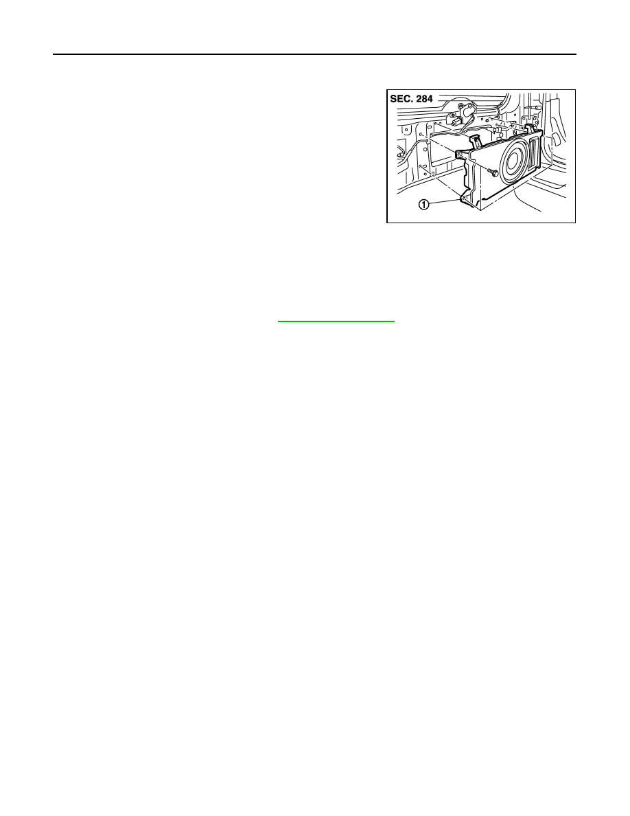
AV-134
< REMOVAL AND INSTALLATION >
[AUDIO SYSTEM]
WOOFER
WOOFER
Exploded View
INFOID:0000000004940281
Removal and Installation
INFOID:0000000004940282
REMOVAL
1.
Remove back door finisher lower. Refer to
.
2.
Remove screws and clips, then disconnect woofer connector and remove the woofer.
INSTALLATION
Install in the reverse order of removal.
JPNIA1698ZZ
1.
Woofer
Revision: 2009 March
2009 Z12
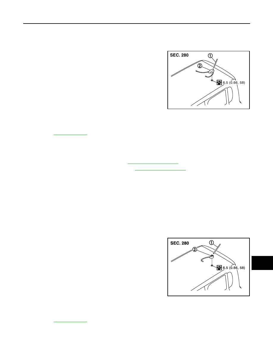
AV
ANTENNA BASE
AV-135
< REMOVAL AND INSTALLATION >
[AUDIO SYSTEM]
C
D
E
F
G
H
I
J
K
L
M
B
A
O
P
ANTENNA BASE
MODELS WITH SATELLITE RADIO SYSTEM
MODELS WITH SATELLITE RADIO SYSTEM : Exploded View
INFOID:0000000004960651
MODELS WITH SATELLITE RADIO SYSTEM : Removal and Installation
INFOID:0000000005087559
REMOVAL
1.
Remove luggage side upper finisher. Refer to
2.
Remove assist grip and headlining clips. Refer to
3.
Pull headlining (rear). Obtain a service area.
4.
Remove antenna base mounting nut.
5.
Remove antenna base.
INSTALLATION
Install in the reverse order of removal.
CAUTION:
Be careful about tightening torque. Antenna sensitivity becomes poor, and when it is excessive, roof
panel may be deformed, when antenna base mounting nut tightening torque is loose.
MODELS WITHOUT SATELLITE RADIO SYSTEM
MODELS WITHOUT SATELLITE RADIO SYSTEM : Exploded View
INFOID:0000000005087549
JPNIA1699GB
1.
Antenna rod
2.
Antenna base
for symbols in the figure.
JSNIA1962GB
1.
Antenna rod
2.
Antenna base
for symbols in the figure.
Revision: 2009 March
2009 Z12

AV-136
< REMOVAL AND INSTALLATION >
[AUDIO SYSTEM]
ANTENNA BASE
MODELS WITHOUT SATELLITE RADIO SYSTEM : Removal and Installation
INFOID:0000000005087550
REMOVAL
1.
Remove luggage side upper finisher. Refer to
2.
Remove assist grip and headlining clips. Refer to
.
3.
Pull headlining (rear). Obtain a service area.
4.
Remove antenna base mounting nut.
5.
Remove antenna base.
INSTALLATION
Install in the reverse order of removal.
CAUTION:
Be careful about tightening torque. Antenna sensitivity becomes poor, and when it is excessive, roof
panel may be deformed, when antenna base mounting nut tightening torque is loose.
Revision: 2009 March
2009 Z12
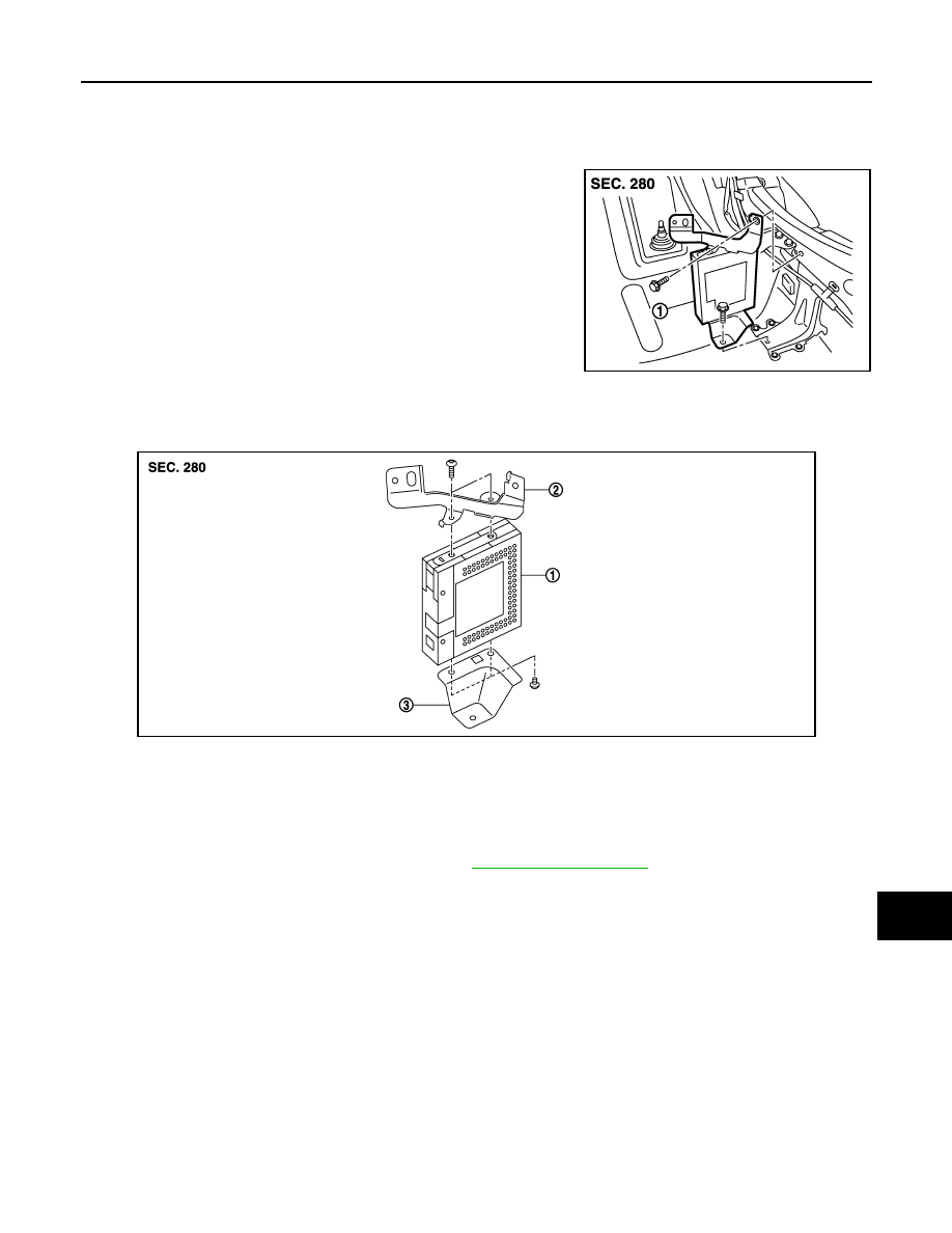
AV
SATELLITE RADIO TUNER
AV-137
< REMOVAL AND INSTALLATION >
[AUDIO SYSTEM]
C
D
E
F
G
H
I
J
K
L
M
B
A
O
P
SATELLITE RADIO TUNER
Exploded View
INFOID:0000000004940285
REMOVAL
DISASSEMBLY
Removal and Installation
INFOID:0000000004940286
REMOVAL
1.
Remove luggage side lower finisher RH. Refer to
.
2.
Disconnect satellite radio tuner connector.
3.
Remove satellite radio tuner screws, harness clip, and antenna feeder clip.
4.
Remove satellite radio tuner and bracket from the vehicle as a single unit.
5.
Remove bracket screws to remove satellite radio tuner.
INSTALLATION
Install in the reverse order of removal.
JPNIA1700ZZ
1.
Satellite radio tuner
JPNIA1701ZZ
1.
Satellite radio tuner
2.
Bracket A
3.
Bracket B
Revision: 2009 March
2009 Z12
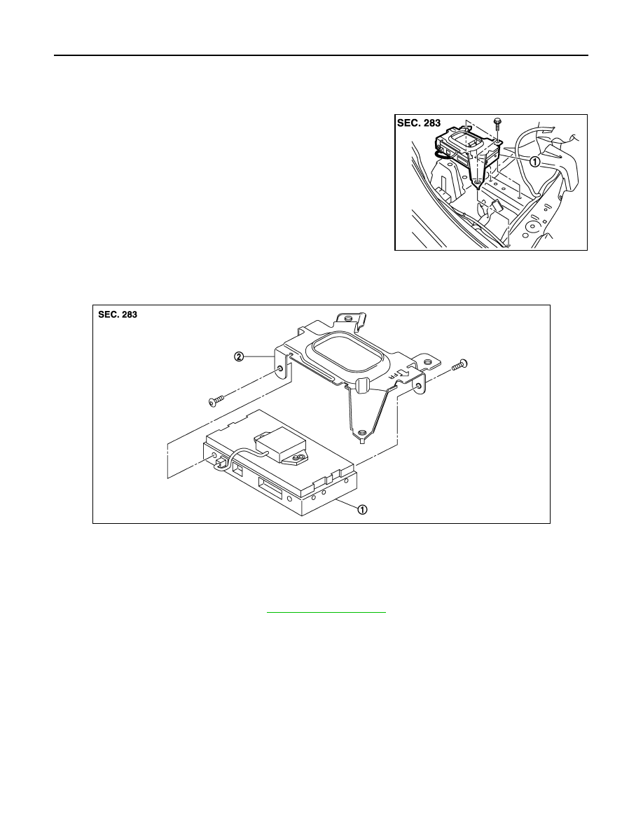
AV-138
< REMOVAL AND INSTALLATION >
[AUDIO SYSTEM]
TEL ADAPTER UNIT
TEL ADAPTER UNIT
Exploded View
INFOID:0000000004940291
REMOVAL
DISASSEMBLY
Removal and Installation
INFOID:0000000004940292
REMOVAL
1.
Remove rear floor spacer RH. Refer to
.
2.
Disconnect TEL adapter unit connector.
3.
Remove TEL adapter unit screws, then remove TEL adapter unit.
4.
Remove bracket screws, and then remove TEL adapter unit.
INSTALLATION
Install in the reverse order of removal.
JPNIA1702ZZ
1.
TEL adapter unit
JPNIA1703ZZ
1.
TEL adapter unit
2.
Bracket
Revision: 2009 March
2009 Z12
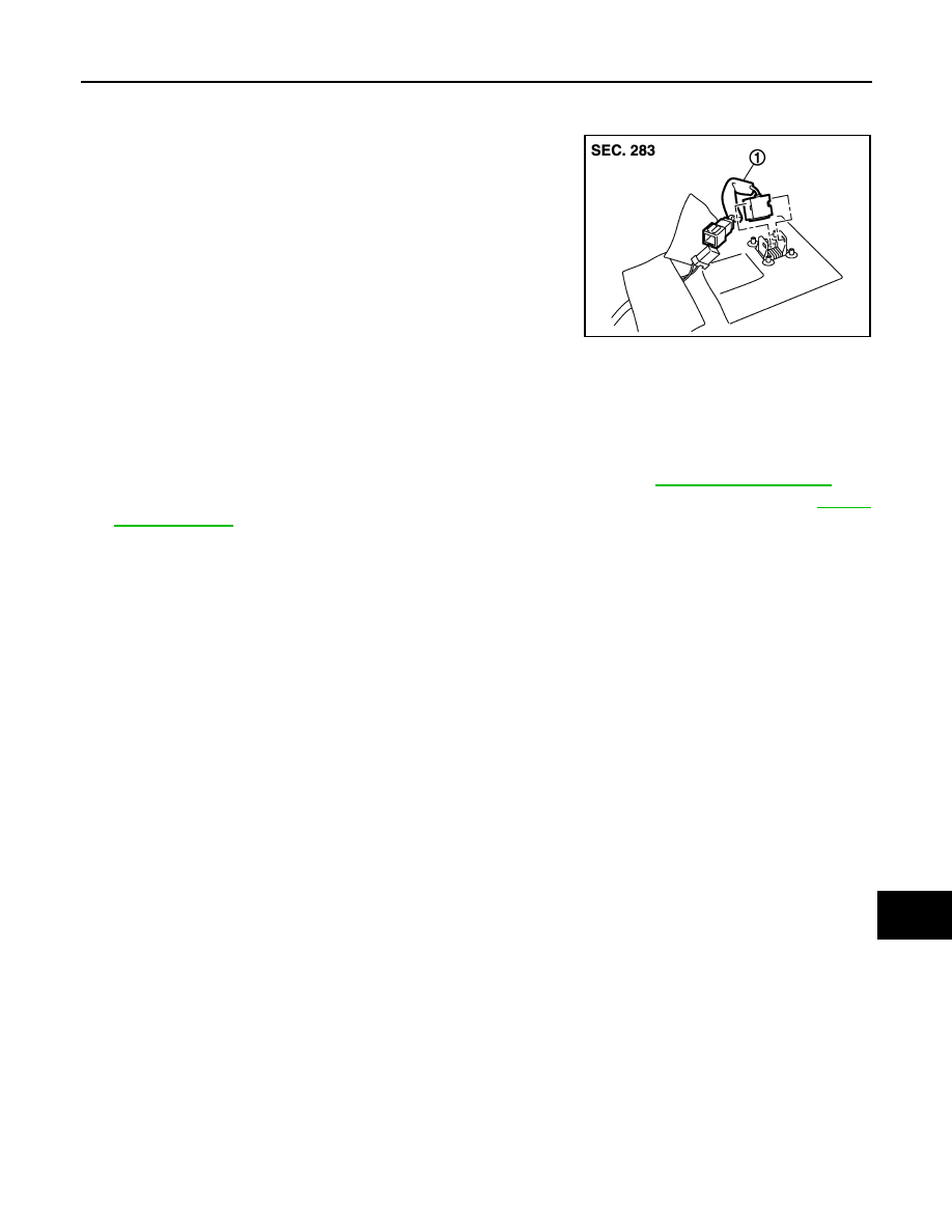
AV
MICROPHONE
AV-139
< REMOVAL AND INSTALLATION >
[AUDIO SYSTEM]
C
D
E
F
G
H
I
J
K
L
M
B
A
O
P
MICROPHONE
Exploded View
INFOID:0000000005096253
Removal and Installation
INFOID:0000000005096254
REMOVAL
1.
Remove front pillar garnish LH and center pillar upper garnish LH. Refer to
.
2.
Remove sun visor assy, map lamp assy, assist grip LH, and inside mirror cover. Refer to
3.
Pull headlining (left front). Obtain a service area.
4.
Remove microphone connector and pawl to remove microphone.
INSTALLATION
Install in the reverse order of removal.
JPNIA1704ZZ
1.
Microphone
Revision: 2009 March
2009 Z12
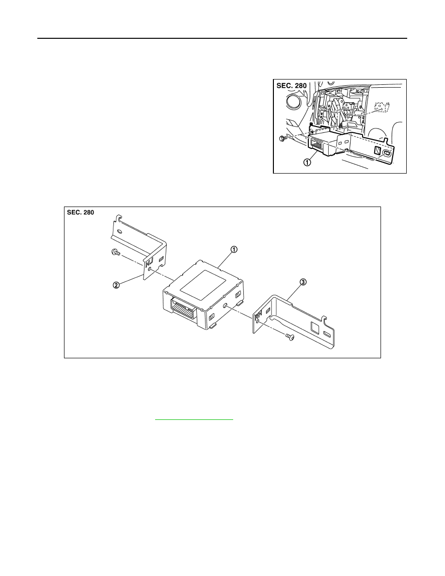
AV-140
< REMOVAL AND INSTALLATION >
[AUDIO SYSTEM]
IPOD ADAPTER
IPOD ADAPTER
Exploded View
INFOID:0000000005096980
REMOVAL
DISASSEMBLY
Removal and Installation
INFOID:0000000005096981
REMOVAL
1.
Remove A/C finisher. Refer to
.
2.
Remove iPod adapter connector and screws to remove iPod adapter.
INSTALLATION
Install in the reverse order of removal.
JPNIA1705ZZ
1.
iPod adapter
JPNIA1706ZZ
1.
iPod adapter
2.
Bracket LH
3.
Bracket RH
Revision: 2009 March
2009 Z12
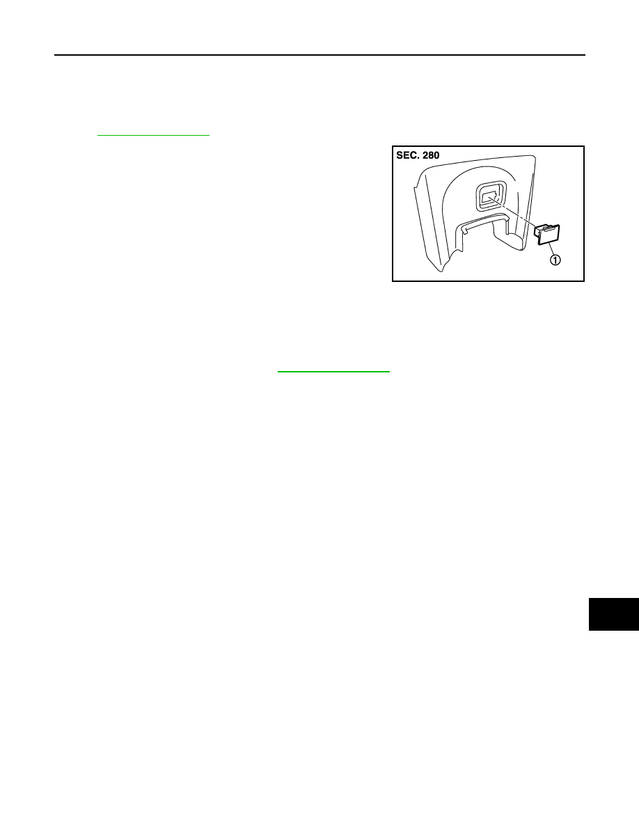
AV
IPOD CONNECTOR
AV-141
< REMOVAL AND INSTALLATION >
[AUDIO SYSTEM]
C
D
E
F
G
H
I
J
K
L
M
B
A
O
P
IPOD CONNECTOR
Exploded View
INFOID:0000000005096982
REMOVAL
.
DISASSEMBLY
Removal and Installation
INFOID:0000000005096983
REMOVAL
1.
Remove instrument lower cover. Refer to
2.
Push the pawl from the back of instrument lower cover to remove iPod connector.
INSTALLATION
Install in the reverse order of removal.
JPNIA1707ZZ
1.
iPod connector
Revision: 2009 March
2009 Z12
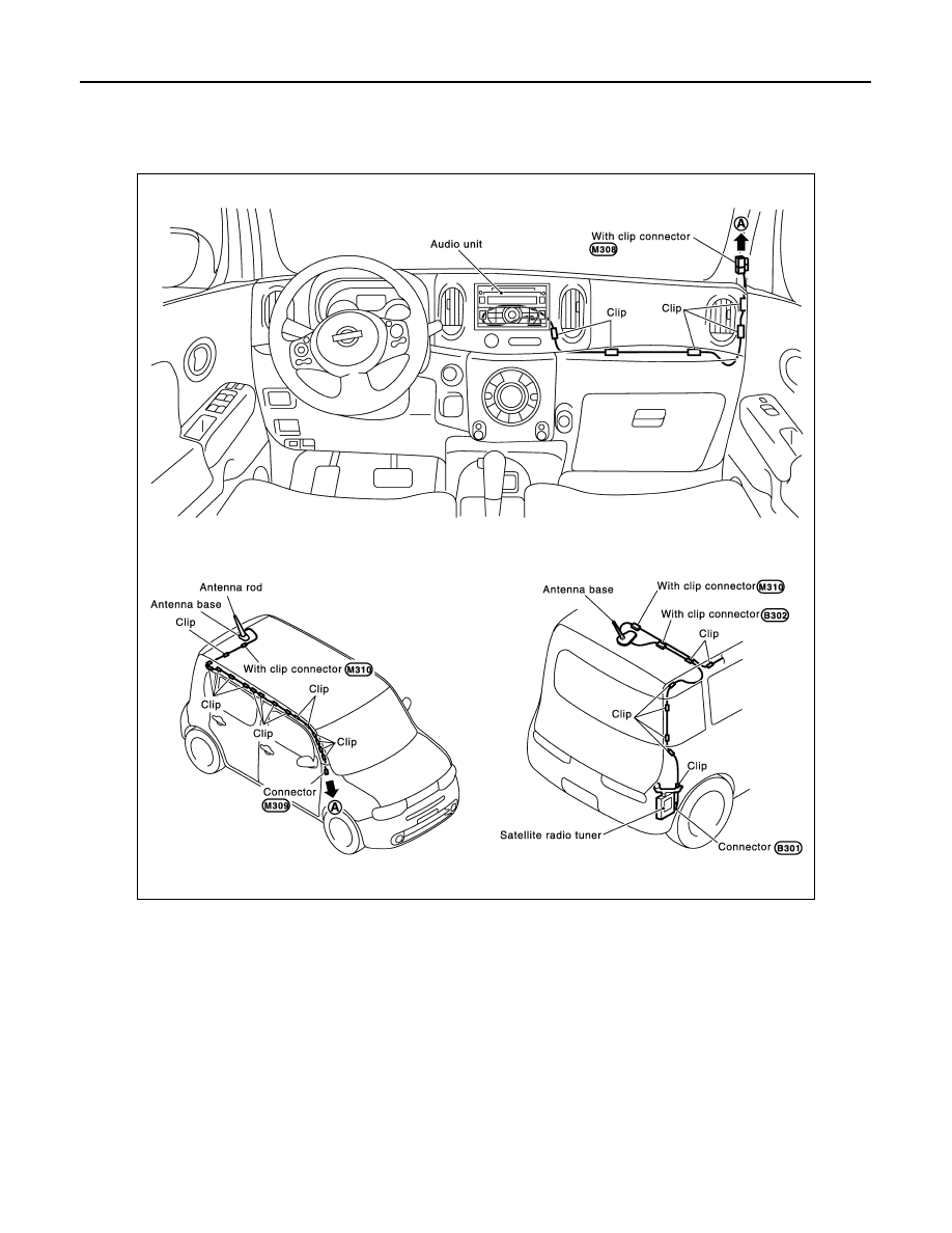
AV-142
< REMOVAL AND INSTALLATION >
[AUDIO SYSTEM]
ANTENNA FEEDER
ANTENNA FEEDER
MODELS WITH SATELLITE RADIO SYSTEM
MODELS WITH SATELLITE RADIO SYSTEM : Harness Layout
INFOID:0000000004940293
MODELS WITHOUT SATELLITE RADIO SYSTEM
JPNIA1724GB
Revision: 2009 March
2009 Z12
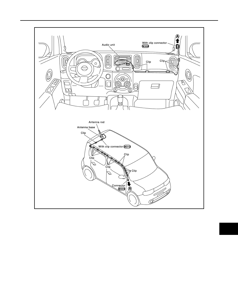
AV
ANTENNA FEEDER
AV-143
< REMOVAL AND INSTALLATION >
[AUDIO SYSTEM]
C
D
E
F
G
H
I
J
K
L
M
B
A
O
P
MODELS WITHOUT SATELLITE RADIO SYSTEM : Harness Layout
INFOID:0000000005096212
JPNIA1723GB
Revision: 2009 March
2009 Z12
Document Outline
- QUICK REFERENCE INDEX
- Table of Contents
- AUDIO LESS
- AUDIO SYSTEM
- BASIC INSPECTION
- SYSTEM DESCRIPTION
- DTC/CIRCUIT DIAGNOSIS
- POWER SUPPLY AND GROUND CIRCUIT
- STEERING SWITCH SIGNAL A CIRCUIT (STEERING SWITCH TO AUDIO UNIT)
- STEERING SWITCH SIGNAL B CIRCUIT (STEERING SWITCH TO AUDIO UNIT)
- STEERING SWITCH SIGNAL GND CIRCUIT (STEERING SWITCH TO AUDIO UNIT)
- STEERING SWITCH SIGNAL A CIRCUIT (AUDIO UNIT TO TEL ADAPTER UNIT)
- STEERING SWITCH SIGNAL B CIRCUIT (AUDIO UNIT TO TEL ADAPTER UNIT)
- STEERING SWITCH SIGNAL GND CIRCUIT (AUDIO UNIT TO TEL ADAPTER UNIT)
- COMMUNICATION SIGNAL CIRCUIT
- REQUEST SIGNAL CIRCUIT (SAT TO AUDIO)
- WOOFER AMP. ON SIGNAL CIRCUIT
- MICROPHONE SIGNAL CIRCUIT
- TELEPHONE ON SIGNAL CIRCUIT
- ECU DIAGNOSIS INFORMATION
- SYMPTOM DIAGNOSIS
- PRECAUTION
- PREPARATION
- REMOVAL AND INSTALLATION
- POWER SUPPLY ROUTING CIRCUIT
- FUSE BLOCK - JUNCTION BOX (J/B)
- FUSE, FUSIBLE LINK AND RELAY BOX
Wyszukiwarka
Podobne podstrony:
Danilo StaMta y Pasto DR PastoMagistrados(120309) DR(AV)
ROZŁAM-Odnowa, AV dokumentalny, Różne, Mszały, ministrantura
23 Fortell om situasjonen? oljen truet hele sørøstkysten av USA
67 AV System
AIWA AV S17
bajkal 95, AV dokumentalny, Syberia
Harman Kardon Amplituner AV AVR171
AV
blokowy av id 57628 Nieznany
AV
AV
Sprawa śpiewów, AV dokumentalny, Różne, Mszały, ministrantura
Syberia w oczach polskich zesłańców, AV dokumentalny, Syberia
Hakerzy NET AV
polaczenia AV
CB y DG Mllin, Rionegro, La?ja? Corporacion Region V2 AT (AV)
Warunki mieszkaniowe Polaków deportowanych do ZSRR 1940-1946, AV dokumentalny, Syberia
2008 anleitung anlage av
więcej podobnych podstron