
( R--J3 CONTROLLER )
PROFIBUS--DP(12M) Interface Function
OPERATOR’S MANUAL
B - 8 1254EN / 0 1
E
FA N U C LTD , 1 9 9 6

In this manual we have tried as much as possible to describe
all the various matters.
However, we cannot describe all the matters which must not
be done, or which cannot be done, because there are so
many possibilities.
Therefore, matters which are not especially described as
possible in this manual should be regarded as “impossible”.

PROFIBUS--DP(12M) Interface Function
OPERATOR’S MANUAL
B--81255EN/01
To be used ONLY with SYSTEM R--J3 Software V5.11P and later
This publication contains proprietary information of FANUC Ltd.
furnished for customer use only. No other uses are authorized without the
express written permission of FANUC Ltd.
FANUC LTD Japan
Oshino--Mura
Yamanashi Prefecture 401--0597
Japan

The descriptions and specifications contained in this manual were in effect
at the time this manual was approved for printing. FANUC Ltd.,
hereinafter referred to as FANUC, reserves the right to discontinue models
at any time or to change specifications or design without notice and
without incurring obligations.
FANUC manuals present descriptions, specifications, drawings,
schematics, bills of material, parts, connections and/or procedures for
installing, disassembling, connecting, operating and programming FANUC
products and/or systems. Such systems consist of robots, extended axes,
robot controllers, application software, the KARELR programming
language, and special tools.
FANUC requires that only persons who have been trained in one or more
approved FANUC Training Course(s) be permitted to install, operate, use,
perform procedures on, repair, and/or maintain FANUC’s products and/or
systems and their respective components. Approved training necessitates
that the courses selected be relevant to the type of system installed and
application performed at the customer site.
Additional information for training or maintenance contact
D
FANUC
Robot Overseas Sales Department
Tel: (0555)84--5690
FAX: (0555)84--5533
D
FANUC Robotics Europe S.A.
Zone Industrielle L--6468 Echternach,
Grand--Duche de Luxembourg
Tel: 352--7277771
FAX: 352--727777403
The information illustrated or contained herein is not to be reproduced,
copied, translated into another language, or transmitted in whole or in part
in any way without the prior written consent of FANUC Ltd.

Safety
B--81254EN/01
s--1
IMPORTANT!
Before operating, servicing or in any other way handling
the robot, the “FANUC Robot SAFETY HANDBOOK
(B-80687EN)” must be thoroughly studied.
SAFETY
B--81254EN/01
s--2
Consider following notes besides the items described in the SAFETY
HANDBOOK.
D
Teaching and manually operation
--
Don’t operate the teach pendant and operator’s panel with the
gloves on your hand.
--
Use a low override speed to increase your control over the robot
when jogging the robot.
--
Visualize the movement the robot will make before you press the
jog keys on the teach pendant.
--
Know the path that can be used to escape from a moving robot;
make sure the escape path is never blocked.
--
The area near the robot must be clean and free of oil, water, or
debris.
D
Production operation
--
Understand the complete task the robot is programmed to perform
before initiating production operation.
--
Know the location and status of all switches, sensors, and control
signals that could cause the robot to move.
--
Know where the EMERGENCY STOP buttons are located on both
the robot control and external control devices. Be prepared to press
these buttons in an emergency.
--
Never assume that a program is complete if the robot is not
moving. The robot could be waiting for an input signal that will
permit it to continue activity.
WARNING
This equipment generates, uses, and can radiate radio
frequency energy and if not installed and used in
accordance with the instruction manual, may cause
interference to radio communications. As temporarily
permitted by regulation, it has not been tested for
compliance with the limits for Class A computing devices
pursuant to subpart J of Part 15 of FCC Rules, which are
designed to provide reasonable protection against such
interference. Operation of the equipment in a residential
area is likely to cause interference, in which case the user,
at his own expense, will be required to take whatever
measure may be required to correct the interference.

Table of Contents
B--81224EN/01
Safety
s- -1
. . . . . . . . . . . . . . . . . . . . . . . . . . . . . . . . . . . . . . . . . . . . . . . . . . . . . . . . . . . . . . . . . . . . . . . . . . . . . . . .
Chapter 1
INTRODUCTION
1--1
. . . . . . . . . . . . . . . . . . . . . . . . . . . . . . . . . . . . . . . . . . . . . . . . . . . . . . . . . . . . . .
Chapter 2
SYSTEM OVERVIEW
2--1
. . . . . . . . . . . . . . . . . . . . . . . . . . . . . . . . . . . . . . . . . . . . . . . . . . . . . . . . . .
2.1 FUNCTION OVERVIEW
2--1
. . . . . . . . . . . . . . . . . . . . . . . . . . . . . . . . . . . . . . . . . . . . . . . . . . . . . .
2.2 SPECIFICATION OVERVIEW
2--1
. . . . . . . . . . . . . . . . . . . . . . . . . . . . . . . . . . . . . . . . . . . . . . . . .
2.3 FEATURES
2--2
. . . . . . . . . . . . . . . . . . . . . . . . . . . . . . . . . . . . . . . . . . . . . . . . . . . . . . . . . . . . . . . . .
2.4 COMMUNICATION DATA FLOW
2--3
. . . . . . . . . . . . . . . . . . . . . . . . . . . . . . . . . . . . . . . . . . . . . .
Chapter 3
PROFIBUS--DP BOARD
3--1
. . . . . . . . . . . . . . . . . . . . . . . . . . . . . . . . . . . . . . . . . . . . . . . . . . . . . . . .
3.1 PROFIBUS--DP BOARD COMPONENT NAMES
3--2
. . . . . . . . . . . . . . . . . . . . . . . . . . . . . . . . . .
3.2 PROFIBUS--DP BOARD CONNECTORS
3--2
. . . . . . . . . . . . . . . . . . . . . . . . . . . . . . . . . . . . . . . .
3.3 R--J3 MASTER FUNCTION LEDS
3--2
. . . . . . . . . . . . . . . . . . . . . . . . . . . . . . . . . . . . . . . . . . . . . .
3.4 R--J3 SLAVE FUNCTION LEDS
3--3
. . . . . . . . . . . . . . . . . . . . . . . . . . . . . . . . . . . . . . . . . . . . . . . .
3.5 PROFIBUS--DP BOARD INSTALLATION
3--4
. . . . . . . . . . . . . . . . . . . . . . . . . . . . . . . . . . . . . . .
Chapter 4
SETUP PRIOR TO STARTING COMMUNICATION
4--1
. . . . . . . . . . . . . . . . . . . . . . . . . . . . . . .
4.1 DP SLAVE/MASTER SETUP
4--1
. . . . . . . . . . . . . . . . . . . . . . . . . . . . . . . . . . . . . . . . . . . . . . . . . .
4.1.1 Number of Master/Slave Input/Output bytes
4--1
. . . . . . . . . . . . . . . . . . . . . . . . . . . . . . . . . . . . .
4.1.2 Setting the R--J3 Slave Function
4--3
. . . . . . . . . . . . . . . . . . . . . . . . . . . . . . . . . . . . . . . . . . . . . . .
4.2 DP MASTER PARAMETER
4--8
. . . . . . . . . . . . . . . . . . . . . . . . . . . . . . . . . . . . . . . . . . . . . . . . . . .
4.2.1 DP MASTER BUS PARAMETER
4--8
. . . . . . . . . . . . . . . . . . . . . . . . . . . . . . . . . . . . . . . . . . . . .
4.2.2 DP MASTER SLAVE PARAMETER
4--11
. . . . . . . . . . . . . . . . . . . . . . . . . . . . . . . . . . . . . . . . . .
4.3 DP MASTER I/O CONFIGURATION
4--17
. . . . . . . . . . . . . . . . . . . . . . . . . . . . . . . . . . . . . . . . . . . .
4.3.1 DP MASTER DIGITAL I/O CONFIGURATION
4--17
. . . . . . . . . . . . . . . . . . . . . . . . . . . . . . . . .
4.3.2 DP MASTER ANALOG I/O CONFIGURATION
4--19
. . . . . . . . . . . . . . . . . . . . . . . . . . . . . . . . .
Chapter 5
DIAGNOSTIC DATA OUTPUT BY A SLAVE COMMUNICATING WITH THE R--J3 MASTER
5--1
. . . . . . . . . . . . . . . . . . . . . . . . . . . . . . . . . . . . . . . . . . . . . . . . . . . . . . . . . . . . . . . . . . . . . . . . . . . . . .
5.1 DP MASTER DIAGNOSTIC DATA
5--1
. . . . . . . . . . . . . . . . . . . . . . . . . . . . . . . . . . . . . . . . . . . . .
Chapter 6
COMMUNICATION WITH DP MASTER (CLASS 2)
6--1
. . . . . . . . . . . . . . . . . . . . . . . . . . . . . . .

TABLE OF CONTENTS
B--81224EN/01
vi
Chapter 7
ERROR CODES AND RECOVERY
7--1
. . . . . . . . . . . . . . . . . . . . . . . . . . . . . . . . . . . . . . . . . . . . . .
Appendix A
GSD FILE FOR R--J3 PROFIBUS--DP SLAVE
A--1
. . . . . . . . . . . . . . . . . . . . . . . . . . . . . . . . . . . . .
Appendix B
GSD FILE FOR R--J3 PROFIBUS--DP MASTER
B--1
. . . . . . . . . . . . . . . . . . . . . . . . . . . . . . . . . . .
Appendix C
MENU MAP FOR R--J3 PROFIBUS--DP INTERFACE FUNCTION
C--1
. . . . . . . . . . . . . . . . . . .
List of Procedures
Procedure 3--1 Installing PROFIBUS--DP Board
3--4
. . . . . . . . . . . . . . . . . . . . . . . . . . . . . . . . . . . . . .
Procedure 4--1 Displaying DP SLAVE SETUP Screen
4--5
. . . . . . . . . . . . . . . . . . . . . . . . . . . . . . . . .
Procedure 4--2 Displaying DP MASTER SETUP Screen
4--7
. . . . . . . . . . . . . . . . . . . . . . . . . . . . . . .
Procedure 4--3 Displaying DP MASTER BUS PARAMETER Screen
4--9
. . . . . . . . . . . . . . . . . . . . .
Procedure 4--4 Displaying DP MASTER SLAVE PARAMETER Screen
4--13
. . . . . . . . . . . . . . . . . . .
Procedure 4--5 Displaying DP MASTER DIGITAL I/O CONFIG Screen
4--17
. . . . . . . . . . . . . . . . . .
Procedure 4--6 Displaying DP MASTER ANALOG I/O CONFIG Screen
4--24
. . . . . . . . . . . . . . . . . .
Procedure 5--1 Displaying the DP MASTER DIAGNOSTIC DATA
5--2
. . . . . . . . . . . . . . . . . . . . . . .
List of Figures
Figure 2--1. Example System Configuration
2--1
. . . . . . . . . . . . . . . . . . . . . . . . . . . . . . . . . . . . . . . . . .
Figure 2--2. R--J3 Master Function Data Flow
2--3
. . . . . . . . . . . . . . . . . . . . . . . . . . . . . . . . . . . . . . . . .
Figure 2--3. R--J3 DP Slave Function Data Flow
2--3
. . . . . . . . . . . . . . . . . . . . . . . . . . . . . . . . . . . . . . .
Figure 3--1. PROFIBUS BOARD
3--1
. . . . . . . . . . . . . . . . . . . . . . . . . . . . . . . . . . . . . . . . . . . . . . . . . .
Figure 3--2. R--J3 Master LEDs
3--2
. . . . . . . . . . . . . . . . . . . . . . . . . . . . . . . . . . . . . . . . . . . . . . . . . . . .
Figure 3--3. R--J3 Slave LEDs
3--3
. . . . . . . . . . . . . . . . . . . . . . . . . . . . . . . . . . . . . . . . . . . . . . . . . . . . .
Figure 3--4. Circuit Breaker and Latch of R--J3 Controller
3--5
. . . . . . . . . . . . . . . . . . . . . . . . . . . . . . .
Figure 3--5. Installing the R--J3 PROFIBUS--DP Interface Board
3--6
. . . . . . . . . . . . . . . . . . . . . . . . . .
Figure 3--6. Cable clamp
3--6
. . . . . . . . . . . . . . . . . . . . . . . . . . . . . . . . . . . . . . . . . . . . . . . . . . . . . . . . .
Figure 4--1. Limits on the Number of Master/Slave input/output bytes
4--2
. . . . . . . . . . . . . . . . . . . . .
Figure 4--2. Master Input/Output Data Area
4--13
. . . . . . . . . . . . . . . . . . . . . . . . . . . . . . . . . . . . . . . . . .
Figure 4--3. Analog Input Data Flow
4--22
. . . . . . . . . . . . . . . . . . . . . . . . . . . . . . . . . . . . . . . . . . . . . . . .
Figure 4--4. Analog Output Data Flow
4--22
. . . . . . . . . . . . . . . . . . . . . . . . . . . . . . . . . . . . . . . . . . . . . . .
Figure 4--5. R--J3 Analog Input Data Position in Analog Slave Area
4--23
. . . . . . . . . . . . . . . . . . . . . . .
Figure 4--6. R--J3 Analog Output Data Position in Analog Slave Area
4--23
. . . . . . . . . . . . . . . . . . . . . .
Figure C--1. Screens for R--J3 PROFIBUS--DP interface function
C--1
. . . . . . . . . . . . . . . . . . . . . . . . .

TABLE OF CONTENTS
B--81224EN/01
vii
List of Tables
Table 2--1. Specification Overview
2--1
. . . . . . . . . . . . . . . . . . . . . . . . . . . . . . . . . . . . . . . . . . . . . . . .
Table 3--1. PROFIBUS--DP Board Connectors
3--2
. . . . . . . . . . . . . . . . . . . . . . . . . . . . . . . . . . . . . . .
Table 3--2. R--J3 Master LEDs
3--2
. . . . . . . . . . . . . . . . . . . . . . . . . . . . . . . . . . . . . . . . . . . . . . . . . . .
Table 3--3. R--J3 Slave LEDs
3--3
. . . . . . . . . . . . . . . . . . . . . . . . . . . . . . . . . . . . . . . . . . . . . . . . . . . .
Table 4--1. Number of Master/Slave Input/Output bytes
4--1
. . . . . . . . . . . . . . . . . . . . . . . . . . . . . . .
Table 4--2. The configuration data for the R--J3 slave
4--3
. . . . . . . . . . . . . . . . . . . . . . . . . . . . . . . . . .
Table 4--3. The Station_status of parameter data for the R--J3 slave
4--4
. . . . . . . . . . . . . . . . . . . . . .
Table 4--4. DP SLAVE SETUP Screen
4--5
. . . . . . . . . . . . . . . . . . . . . . . . . . . . . . . . . . . . . . . . . . . . .
Table 4--5. DP MASTER SETUP Screen
4--6
. . . . . . . . . . . . . . . . . . . . . . . . . . . . . . . . . . . . . . . . . . .
Table 4--6. Initialization data of slave parameter
4--6
. . . . . . . . . . . . . . . . . . . . . . . . . . . . . . . . . . . . .
Table 4--7. DP MASTER BUS PARAMETER Screen
4--8
. . . . . . . . . . . . . . . . . . . . . . . . . . . . . . . . .
Table 4--8. DP MASTER SLAVE PARAMETER Screen
4--11
. . . . . . . . . . . . . . . . . . . . . . . . . . . . . .
Table 4--9. DP MASTER DIGITAL I/O CONFIG Screen
4--17
. . . . . . . . . . . . . . . . . . . . . . . . . . . . . .
Table 4--10. DP MASTER ANALOG I/O CONFIG Screen(1)
4--19
. . . . . . . . . . . . . . . . . . . . . . . . . .
Table 4--11. Data Configuration When Only Analog Inputs are Enabled
4--19
. . . . . . . . . . . . . . . . . . .
Table 4--12. Data Configuration When Only Analog Outputs are Enabled
4--20
. . . . . . . . . . . . . . . . .
Table 4--13. Data Configuration for Arc Welding Input Signals and Analog Inputs
4--20
. . . . . . . . . .
Table 4--14. Data Configuration for Arc Welding Output Signals and Analog Outputs
4--20
. . . . . . .
Table 4--15. DP MASTER ANALOG I/O CONFIG Screen(2)
4--21
. . . . . . . . . . . . . . . . . . . . . . . . . .
Table 5--1. DP MASTER DIAGNOSTIC DATA screen
5--1
. . . . . . . . . . . . . . . . . . . . . . . . . . . . . . . .
1
INTRODUCTION
B--81254EN/01
This manual explains the PROFIBUS--DP (12M) interface functions used
by the FANUC SYSTEM R--J3 (referred to as the R--J3). The descriptions
are based on the PROFIBUS standards stipulated in DIN 19245 Parts 1
and 3.
Other manuals provided with this product describe system
settings/operations other than those described in this manual. These
manuals need not be referenced by readers of this manual. Users are,
however, urged to observe the safety precautions described at the
beginning of each of these manuals.
Manuals specific
to individual tools
Each of these manuals describes the procedure for
setting up and operating the software for the related
tool, such as a spot welding tool or handling tool.
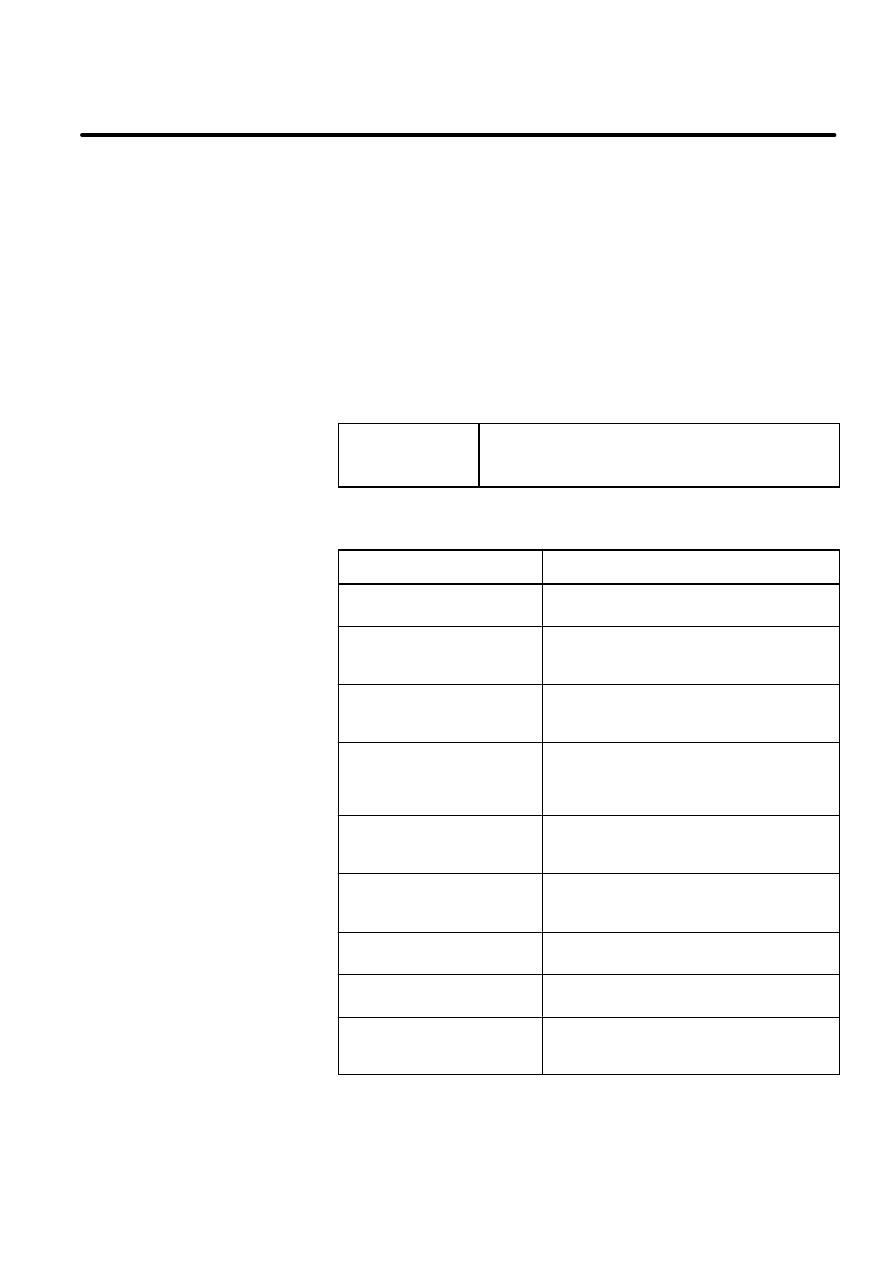
The contents of each section of this manual are briefly described below.
SECTION
Description
Chapter 2, SYSTEM
OVERVIEW
Briefly describes the functions of the R--J3
PROFIBUS--DP (12M) interface.
Chapter 3, PROFIBUS--DP
BOARD
Describes the PROFIBUS board required to
enable the R--J3 to communicate using the
PROFIBUS--DP interface.
Chapter 4, SETUP PRIOR
TO STARTING
COMMUNICATION
Describes how the R--J3 master/slave
function must be set up before communication
can be started.
Chapter 5, DIAGNOSTIC
DATA OUTPUT BY A SLAVE
COMMUNICATING WITH
THE R--J3 MASTER
Describes how to determine the causes of
problems that may occur during
communication between the R--J3 master and
slave.
Chapter 6,
COMMUNICATION WITH DP
MASTER (CLASS 2)
Describes the communication with DP
Master(Class 2).
Chapter 7, ERROR CODES
AND RECOVERY
Describes the alarm codes related to the
PROFIBUS--DP functions, their causes, and
the corresponding countermeasures.
Appendix A, GSD File for
R--J3 PROFIBUS--DP Slave
Use this file on the configurator (DP Slave
Class2) to setup R--J3 PROFIBUS--DP.
Appendix B, GSD File for
R--J3 PROFIBUS--DP Master
Use this file on the configurator (DP Master
Class2) to setup R--J3 PROFIBUS--DP.
Appendix C, MENU Map for
R--J3 PROFIBUS--DP
Interface Function
When you look for the PROFIBUS--DP screen
you want to display, use this MENU MAP.
Purpose of this Manual
Related Manuals
How to Use this
Manual
B--81254EN/01
1--2
1. ENTER YOUR CHAPTER TITLE HERE
This manual includes information essential to the safety of personnel,
equipment, software, and data. This information is indicated by headings
and boxes in the text.
WARNING
Information appearing under WARNING concerns the
protection of personnel. It is boxed and in bold type to set
it apart from other text.
CAUTION
Information appearing under CAUTION concerns the protection
of equipment, software, and data. It is boxed to set it apart
from other text.
NOTE Information appearing next to NOTE concerns related information
or useful hints.
Conventions Used in
this Manual
2
SYSTEM OVERVIEW
B--81254EN/01
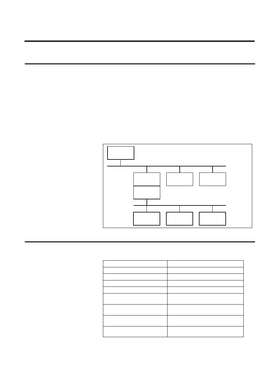
This section briefly describes the functions of the R--J3 PROFIBUS--DP
(12M) interface.
The PROFIBUS--DP (12M) interface function is implemented on a two
PROFIBUS--DP interface board. The PROFIBUS Master Interface board
is used for the DP master (class 1) function (referred to as the master
function) and The PROFIBUS Slave Interface board is used for the DP
slave function (referred to as the slave function). These functions can be
connected to separate networks.
On one of the networks to which it is connected, the R--J3 operates as a
master to exchange I/O data with peripheral equipment (such as a welding
equipment). On the other network, the R--J3 operates as a slave to
exchange I/O data with a unit such as a PLC, used to integrate cells. This
function is supported only for the R--J3.
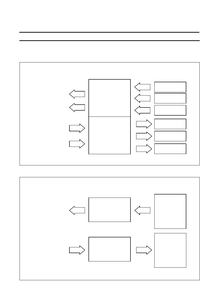
Figure 2--1. Example System Configuration
PLC
DP Master
R--J3
DP Slave #1
DP Slave
device #2
Network 1
R--J3
DP Master
DP Slave
device #3
Network 2
DP Slave
device #1
DP Slave
device #2
DP Slave
device #3
Networks 1 and 2 are independent of each other.
Table 2--1. Specification Overview
Item
Specification
Baud rate
max. 12 Mbauds
Supported types
DP slave and master
Number of inputs
1024 total for both slave and master
Number of outputs
1024 total for both slave and master
Number of analog inputs*
2 channels per one device
(max. 6 channels)
Number of analog outputs*
2 channels per one device
(max. 6 channels)
Supported signal types
Digital, UOP, group, analog, and arc
welding signals
Number of slave nodes that can
be connected in a master mode
32
* DP master function only
NOTE Analog and arc welding signals can be transmitted only with the
master function.
2.1
FUNCTION OVERVIEW
2.2
SPECIFICATION
OVERVIEW

B--81254EN/01
2--2
1. ENTER YOUR CHAPTER TITLE HERE
The R--J3 PROFIBUS--DP interface has the following features.
D
The DP master and slave functions operate independently of each
other.
D
The PROFIBUS--DP interface can be used together with other I/O
devices such as process I/O boards and the FANUC I/O Unit Model B.
D
A dedicated signal (UOP) can be allocated to I/O data exchanged via
the PROFIBUS--DP interface. The default setting allocates the signal
to I/O data transmitted with the slave function.
D
The signals and states listed below can be output to the
PROFIBUS--DP by reflecting them in DOs using the I/O Interconnect
function. The TP screen can be used to specify the DO to which a
particular signal or state is to be output. Refer to the manual provided
with the relevant tool.
--
CE marking 3--mode switch
--
SOP START/RESET
--
Cause of emergency stop, in the following cases:
TP emergency stop
SOP emergency stop
UOP immediately stop software signal (*IMSTP)
Open deadman or fence switch (FENCE1 and FENCE2)
External emergency stop (EMGIN1 and EMGIN2)
NOTE A DO that indicates the cause of an emergency stop is turned off
once the cause has been eliminated, even if the system remains in an alarm
state.
D
The PROFIBUS--DP interface can be used with arc welding and
sealing equipments. Refer to the manual provided with the relevant
tool for details.
2.3
FEATURES
B--81254EN/01
2--3
1. ENTER YOUR CHAPTER TITLE HERE
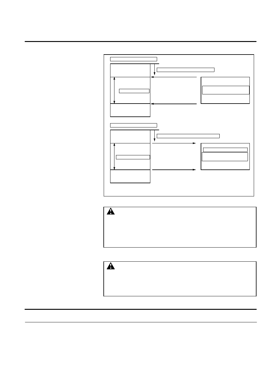
The contents of this section relate to the example system configuration
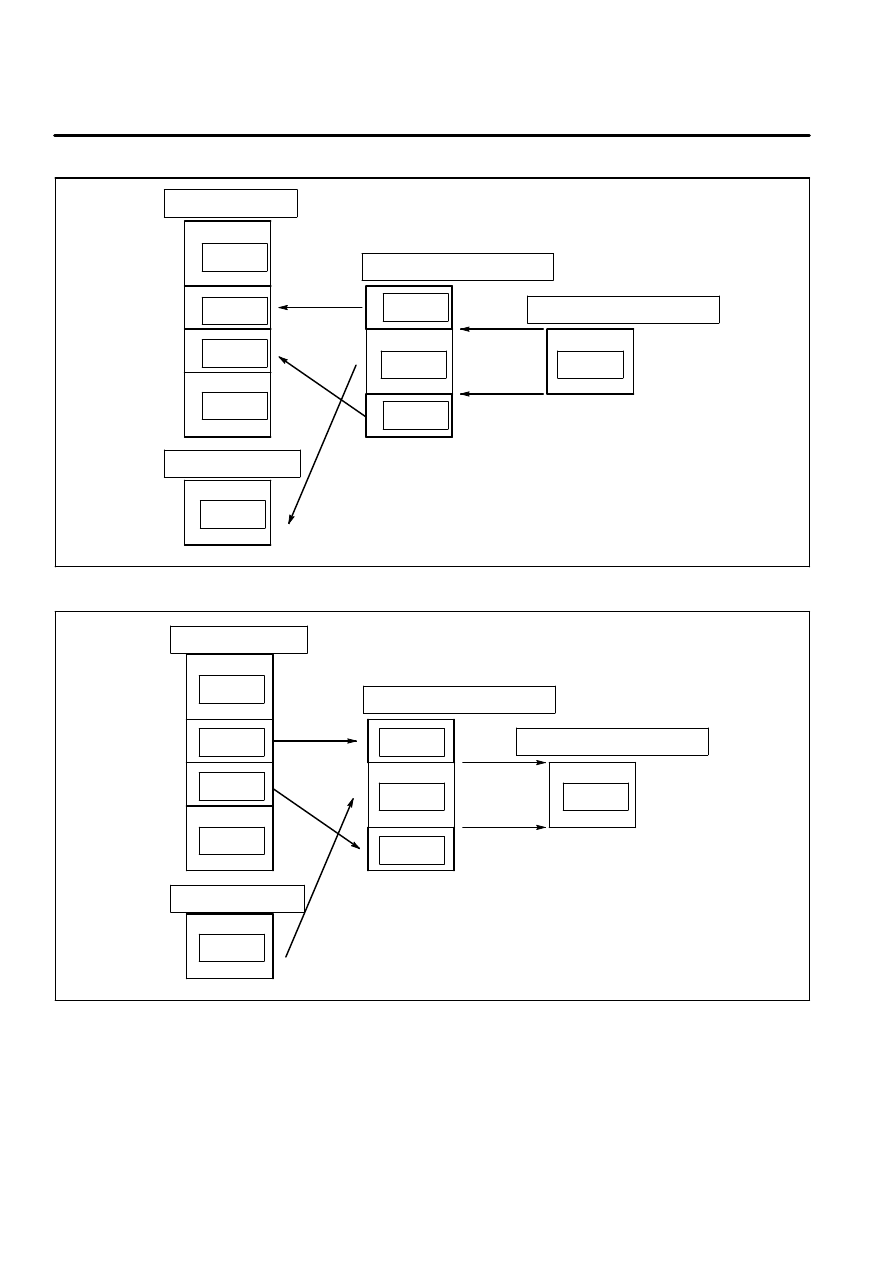
illustrated in Figure 2--1.
Figure 2--2. R--J3 Master Function Data Flow
Rack 66
Slot 1
DI, GI, UI
Slave #1
output data
R--J3 Controller
PROFIBUS Master board
master input/output data area
Slave device
Slave #1
input data
Slave #2
output data
Slave #3
output data
Slave #2
input data
Slave #3
input data
WI, WSK, AI
Rack 66
Slot 1
DO, GO, UO
WO, WST, AO
Master input
data area
Master output
data area
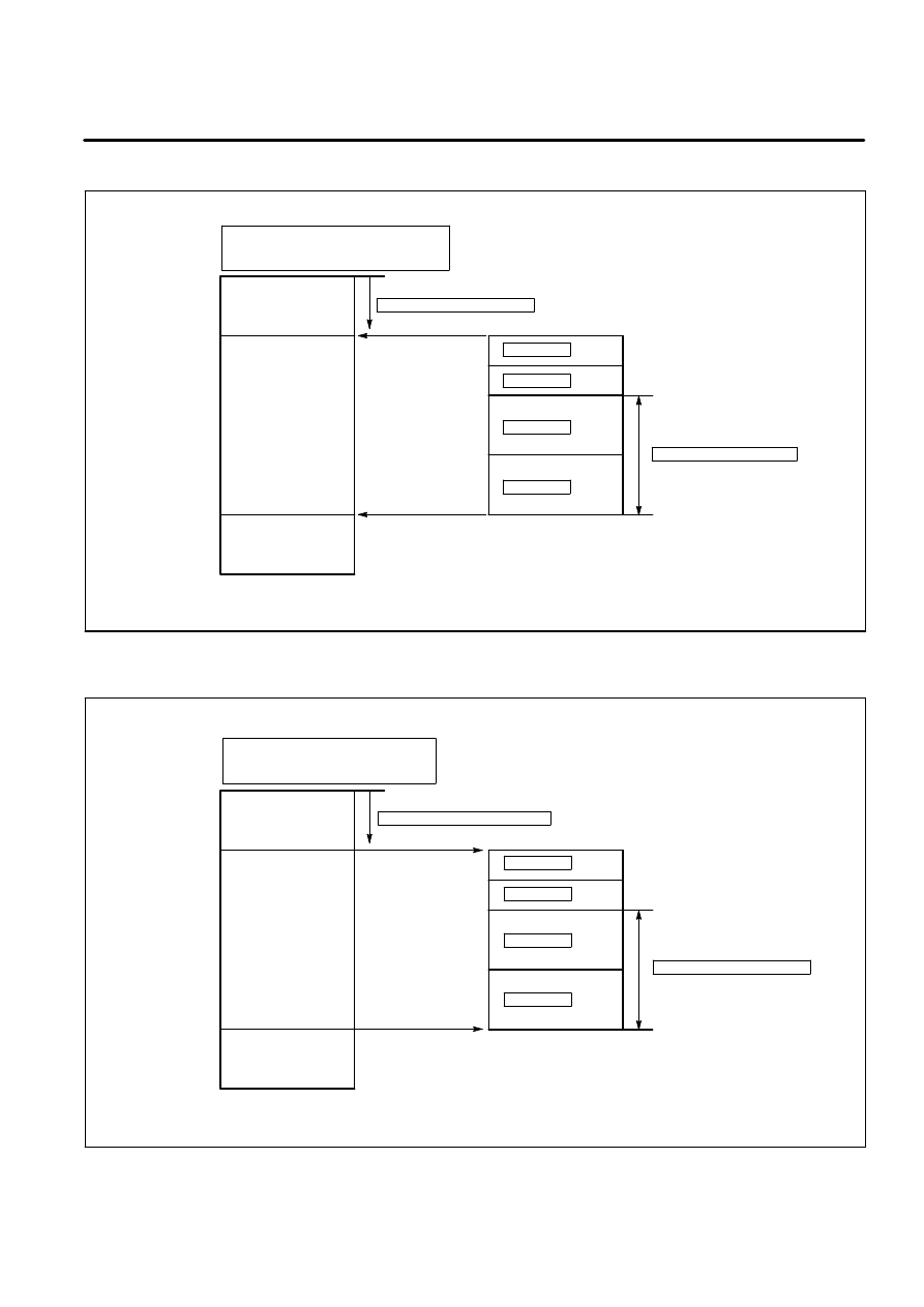
Figure 2--3. R--J3 DP Slave Function Data Flow
Master output data
R--J3 Controller
PROFIBUS Slave board
slave input/output data area
Master device
Master input data
Slave input data area
Slave output data area
Rack 67
Slot 1
DI, GI, UI
Rack 67
Slot 1
DO, GO, UO
2.4
COMMUNICATION
DATA FLOW
3
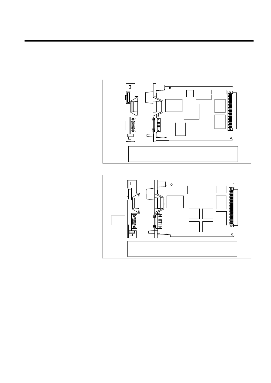
PROFIBUS--DP BOARD
B--81254EN/01
This section describes the PROFIBUS board required to enable
PROFIBUS--DP communication.
Figure 3--1. PROFIBUS BOARD
[PROFIBUS master board]
JN1: Nine--pin D--Sub female connector
PROFIBUS bus interface (master function)
JN1
[PROFIBUS master board]
JN2: Nine--pin D--Sub female connector
PROFIBUS bus interface (slave function)
JN2
B--81254EN/01
3--2
1. ENTER YOUR CHAPTER TITLE HERE
D
R--J3 Master function connector
D
R--J3 Master function status indication LEDs
D
R--J3 Slave function connector
D
R--J3 Slave function status indication LEDs
Table 3--1. PROFIBUS--DP Board Connectors
CONNECTOR
DESCRIPTION
JN1
Connector for cable used to connect the R--J3 master
function
JN2
Connector for cable used to connect the R--J3 slave
function
Figure 3--2. R--J3 Master LEDs
LED1
LED2
JN1
NOTE The face plate is indicated by a broken line.
Table 3--2. R--J3 Master LEDs
LED
DESCRIPTION
LED1
Turned on if the CPU of this board starts.
Usually ON.
LED2
Turned on when the R--J3 master contains the token.
Usually ON.
3.1
PROFIBUS--DP BOARD
COMPONENT NAMES
3.2
PROFIBUS--DP BOARD
CONNECTORS
3.3
R--J3 MASTER
FUNCTION LEDS
B--81254EN/01
3--3
1. ENTER YOUR CHAPTER TITLE HERE
Figure 3--3. R--J3 Slave LEDs
JN2
LED1
LED2
LED3
LEDB
NOTE The face plate is indicated by a broken line.
Table 3--3. R--J3 Slave LEDs
LED
DESCRIPTION
LED1
Turned on if the CPU of this board starts.
Usually ON.
LED2
Turned on when the R--J3 slave is performing DI/DO
transfer according to valid parameter and configuration
data (see Section 4.1.2) received from the DP master.
LED3
Turned off the following cases:
--
The R--J3 slave has received no parameter or
configuration data from DP master since the R--J3 was
switched on. Probable causes are an incorrectly
connected cable or the DP master not being switched
on.
--
The R--J3 slave has received the invalid parameter or
configuration data.
--
The R--J3 slave cannot communicate with the DP
master. Probable causes are a detached
communication cable or that the DP master has been
switched off.
LEDB
Turned on if the parity error occurs on this board.
Usually OFF.
3.4
R--J3 SLAVE
FUNCTION LEDS
B--81254EN/01
3--4
1. ENTER YOUR CHAPTER TITLE HERE
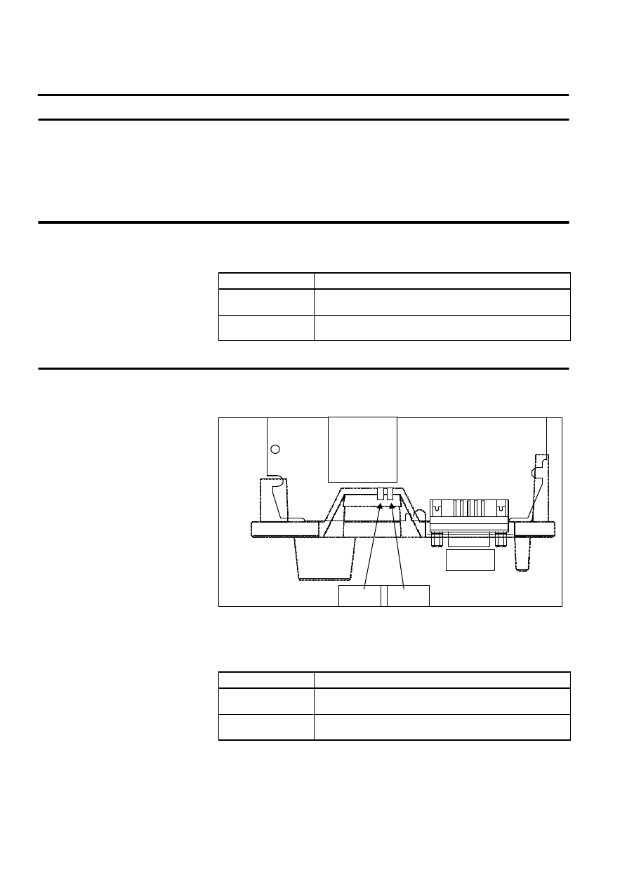
The PROFIBUS Master and Slave board can be installed in any
unoccupied option slot in the R--J3 controller.
WARNING
Before attempting to attach or detach a unit or board,
completely disconnect the power to the controller. Failure
to do so presents a serious risk of injury.
Procedure 3--1
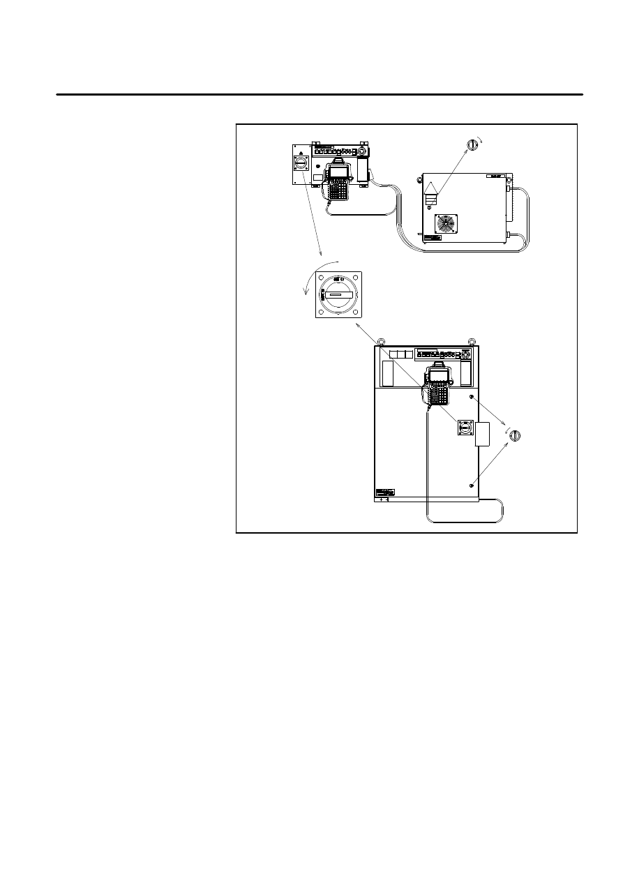
Installing PROFIBUS--DP Board
1 Switch off the power to the controller.
2 Disconnect electrical power from the controller. Turn the circuit
breaker to the OFF position.
WARNING
Even when the disconnect switch and circuit breaker are
set to their OFF positions, hazardous voltages are present
inside the controller. To completely disconnect the
controller, remove the plug of the controller’s power cord
from the wall outlet.
3 Using a standard (flat--blade) screwdriver, release the controller’s front
door by moving the latch to the UNLOCKED position. See
Figure 3--4.
3.5
PROFIBUS--DP BOARD
INSTALLATION
Step
B--81254EN/01
3--5
1. ENTER YOUR CHAPTER TITLE HERE
Figure 3--4. Circuit Breaker and Latch of R--J3 Controller
LOCKED
LOCKED
UNLOCKED
OFF
BREAKER
UN
LOCKED
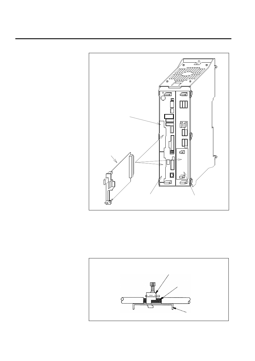
4 Insert the PROFIBUS--DP interface board into any unoccupied option
slot. Do not insert it into a slot intended for a power supply unit.
B--81254EN/01
3--6
1. ENTER YOUR CHAPTER TITLE HERE
Figure 3--5. Installing the R--J3 PROFIBUS--DP Interface Board
SLOT 10
(Mini Slot)
PROFBUS
Interface Board
SLOT 9
(Mini Slot)
SLOT 8
(Wide Mini Slot)
NOTE Partially strip the insulation of the PROFIBUS cable to expose the
shielding, and secure the cable with a metal clamp at the point where the
shielding is exposed. Refer to the relevant Connection/Maintenance
Manual for details.
Figure 3--6. Cable clamp
Clamp fixture
Shield jacket
Shield plate
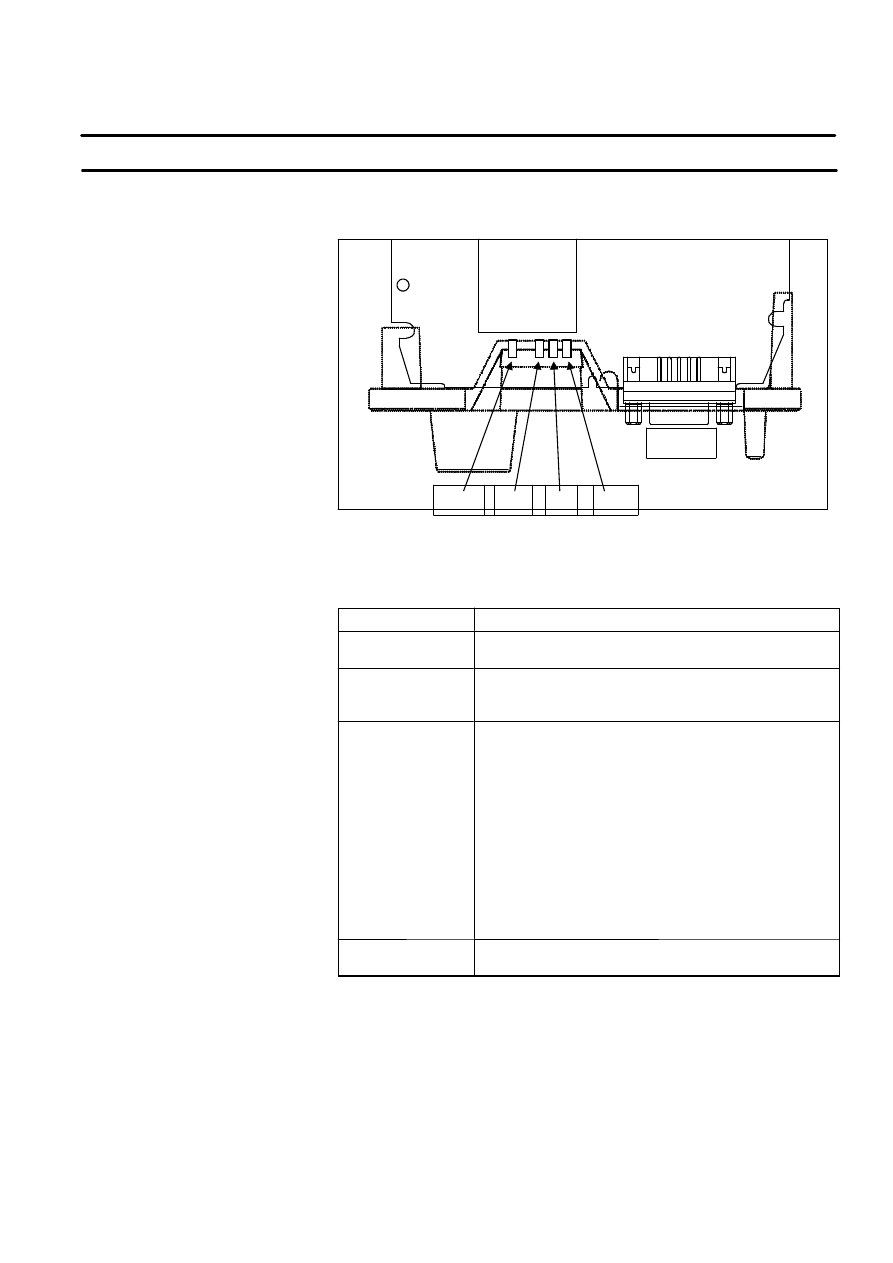
5 Close the controller door. Set the circuit breaker handle or disconnect
switch to the ON position.

B--81254EN/01
3--7
1. ENTER YOUR CHAPTER TITLE HERE
LOCKED
LOCKED
UNLOCKED
ON
BREAKER
UN
LOCKED
4
SETUP PRIOR TO STARTING
COMMUNICATION
B--81254EN/01
This chapter describes the master/slave function settings that must be made
before communication can be started.
This section describes how to set the number of master/slave input/output
bytes and so on.
Setting the number of master/slave input/output bytes The number of
master/slave input/output bytes is default settings as listed in Table 4--1.
Number of input bytes to the master
Number of signals that can be input to
the master
Number of output bytes from the master Number of signals that can be output
from the master
Number of input bytes to the slave
Number of signals that can be input to
the slave
Number of output bytes from the slave
Number of signals that can be output
from the slave
Table 4--1. Number of Master/Slave Input/Output bytes
Signal types
Default settings
Number of input bytes to the slave
8
Number of output bytes from the slave
10
Number of input bytes to the master
24
Number of output bytes from the master
22
The number of input/output bytes can be changed by using Procedure 4--1
or Procedure 4--2 .
For the new settings to become effective, it is necessary to clear all the
I/O assignment data and switch the R--J3 controller power off then on
again.
To use only the slave function, for example, the number of slave
input/output bytes must be set to no more than 128 and the number of
master input/output bytes to 0.
Maximum number of input bytes
128 >= number of input bytes to the slave + number of input bytes to the
master
Maximum number of output bytes
128 >= number of output bytes from the slave + number of output bytes
from the master
4.1
DP SLAVE/MASTER
SETUP
4.1.1
Number of
Master/Slave
Input/Output bytes
Limit on the number of
master/slave input/output
bytes
B--81254EN/01
4--2
1. ENTER YOUR CHAPTER TITLE HERE
Figure 4--1. Limits on the Number of Master/Slave input/output bytes
Slave input
data area
Number of input bytes to
R--J3 slave
Up to 128 bytes
Master input
data area
Slave output
data area
Master output
data area
Up to 128 bytes
Number of input bytes to
R--J3 master
Number of output bytes from
R--J3 slave
Number of output bytes from
R--J3 master
B--81254EN/01
4--3
1. ENTER YOUR CHAPTER TITLE HERE
Setting the DP master that will communicate with the R--J3 slave
Use Procedure 4--1 to set the R--J3 slave address. R--J3 Slave Address is
default settings to 3. For the new R--J3 slave address to become effective,
it is necessary to switch the R--J3 controller power off then on again.
Specify whether to set the consistency flag (configuration data) in the DP
master that communicates with the R--J3 slave. Use Procedure 4--1 to set
this flag. This flag is default settings to OFF. For the new consistency
flag to become effective, it is necessary to switch the R--J3 controller
power off then on again.
The configuration data for the R--J3 slave must be set in special identifying
formats, as listed below.
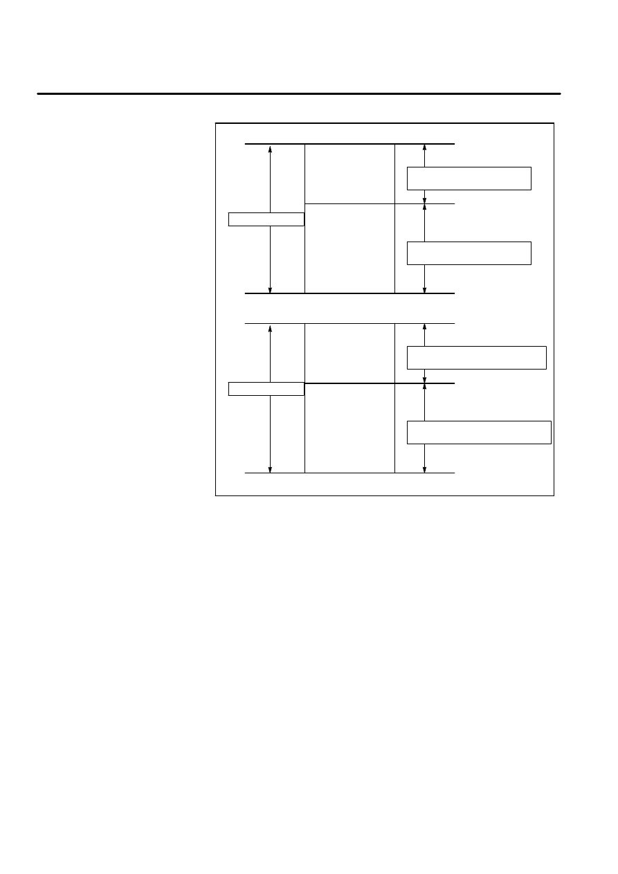
Table 4--2. The configuration data for the R--J3 slave
Byte 1 0xC0
Byte 2
If the outputs bytes number from Master to R--J3 is 8, and the
consistency flag is OFF, for example, byte 2 must be set to 0x07. If the
consistency flag is ON, byte 2 must be set to 0x87.
7
6
5
4
3
2
1
0
Bit--No
MSB
LSB
(Output bytes number from Master to R--J3) -- 1
fixed to 0
consistency flag
ON:1
OFF:0
Byte 3
If the input bytes number to Master from R--J3 is 10, and the consistency
flag is OFF, for example, byte 3 must be set to 0x09.
7
6
5
4
3
2
1
0
Bit--No
MSB
LSB
(Input bytes number to Master from R--J3) -- 1
fixed to 0
consistency flag
ON:1
OFF:0
4.1.2
SETTING THE R--J3
SLAVE FUNCTION
R--J3 Slave Address
Consistency flag for R--J3
Slave Configuration data

B--81254EN/01
4--4
1. ENTER YOUR CHAPTER TITLE HERE
Set the parameter data for the R--J3 slave as follows:
Set Station_status as listed below.
Table 4--3. The Station_status of parameter data for the R--J3 slave
Bit 7
Lock_Req = 1
Bit 6
UnLock_Req = 0
Bit 5
Sync_Req = 0
Bit 4
Freeze_Req = 0
Bit 3
WD_on = 1
Set WD_Fact_1 and WD_Fact_2 to 50 ms or more.
Set Ident_Number to 0x009F (hexadecimal).
Do not set User_Prm_Data.
For details, please refer Appendix A The R--J3 GSD file.
Parameter Data
B--81254EN/01
4--5
1. ENTER YOUR CHAPTER TITLE HERE
Table 4--4. DP SLAVE SETUP Screen
ITEM
Description
OUTPUT BYTES
Output byte number from DP Master to R--J3
INPUT BYTES
Input byte number to DP Master from R--J3
STATION ADDRESS
R--J3 Slave station address
CONSISTENCY FLAG
Specify whether to set consistency flag(configuration data) in the DP Master
that communicates with the R--J3 Slave.
MAX DIGITAL PORT NUM
The maximum point which can be displayed on digital I/O screen.
Procedure 4--1
Displaying DP SLAVE SETUP Screen
1 Press MENUS.
2 Select SETUP.
3 Press F1, [TYPE].
4 Select PROFIBUS.
5 If DP SLAVE SETUP Screen is not displayed, press F3,[OTHER], and
select SLAVE. If F3,[OTHER], is not displayed, press F2,LIST or
NEXT,> or PREV.
You can see the following screen.
DP SLAVE SETUP
1/5
1 OUTPUT BYTES
:
8
2 INPUT BYTES
:
10
3 STATION ADDRESS
:
3
4 CONSISTENCY FLAG
: OFF
5 MAX DIGITAL PORT NUM
: 256
[ TYPE ]
[OTHER ]
>
SETUP PROFIBUS-DP
JOINT
10 %
8
6 To change the setting, set the cursor to the item to be set, and enter a
value by using the numeric keys or function keys.
7 To clear the I/O assignment,
a Press NEXT,>.
b Press F1,CLR_ASG, then the following message is displayed.
”Clear all assignments ?”
c Press F4,YES to clear all I/O assignment.
Step
B--81254EN/01
4--6
1. ENTER YOUR CHAPTER TITLE HERE
8 To save all the PROFIBUS--DP setup data to a file,
a Press FCTN.
b Select SAVE. This will save all the PROFIBUS--DP setup data to
the file, PROFIBUS.SV file, on the default device.
Table 4--5. DP MASTER SETUP Screen
ITEM
Description
OUTPUT BYTES
Output byte number to DP Slave from R--J3
INPUT BYTES
Input byte number from DP Slave to R--J3
SLAVE PARAMETER INIT
The following procedure initializes the slave parameter sets.
CAUTION
Initialization sets all slave parameters to standard values,
canceling all user--set data. If previously set data must be
preserved, make a note of it before performing initialization.
1 Set this item to ON
2 Turn off the controller, then turn it on again.This procedure initializes the slave parameter
set specified for a slave communicating with the R--J3. The slave parameter set for station
NO.3,4,5,6 are set as listed in Table 4--6. The other slave parameter sets are set using the
same initialization data.
MAX DIGITAL PORT NUM
The maximum point which can be displayed on digital I/O screen.
Table 4--6. Initialization data of slave parameter
STATION NO.
DEVICE
The slave parameter set for station
NO.3
24 DIs/8 DOs 0.2 ms for Siemens ET
200B
The slave parameter set for station
NO.4
R--J3 slave
The slave parameter set for station
NO.5
R--J3 slave
The slave parameter set for station
NO.6
Siemens ET 200M
(The installed module in ET 200M are
SM321, SM322, SM331 and SM332.)
B--81254EN/01
4--7
1. ENTER YOUR CHAPTER TITLE HERE
Procedure 4--2
Displaying DP MASTER SETUP Screen
1 Press MENUS.
2 Select SETUP.
3 Press F1, [TYPE].
4 Select PROFIBUS.
5 If DP MASTER SETUP Screen is not displayed, press F3,[OTHER],
and select MASTER. If F3,[OTHER], is not displayed, press F2,LIST
or PREV or NEXT,>. You can see the following screen.
DP MASTER SETUP
1/4
1 OUTPUT BYTES
:
22
2 INPUT BYTES
:
24
3 SLAVE PARAMETER INIT
: OFF
4 MAX DIGITAL PORT NUM
: 256
[ TYPE ]
[OTHER ]
>
SETUP PROFIBUS-DP
JOINT
10 %
22
6 To change the setting, set the cursor to the item to be set, and enter a
value by using the numeric keys or function keys.
7 To clear the I/O assignment,
a Press NEXT,>.
b Press F1,CLR_ASG, then the following message is displayed.
”Clear all assignments ?”
c Press F4,YES to clear all I/O assignment.
8 To save all the PROFIBUS--DP setup data to a file,
a Press FCTN.
b Select SAVE. This will save all the PROFIBUS--DP setup data to
the file, PROFIBUS.SV file, on the default device.
Step

B--81254EN/01
4--8
1. ENTER YOUR CHAPTER TITLE HERE
This section describes how to set the master parameters that must be set
before the R--J3 master function can be used, as well as the slave
parameter to be set for a slave that communicates with the R--J3 master.
The master parameter data consists of data such as bus parameter data. Use
Procedure 4--3 to set the master parameters.
For details, refer to PROFIBUS STANDARD DIN 19245 Part 1 and Draft
Standard PROFIBUS--DP DIN 19245 Part 3.
These parameters may have to be modified if communication between the
R--J3 master and slave proves impossible. Whenever communication is
possible with the default settings, those settings should be left as it. If new
data is specified, it does not become effective until the power is switched
off then on again.
You need not change if there is no necessity because the optimum data has
already been set.
And when the Baudrate is changed, the optimum data is automatically set
as for other data.
Table 4--7. DP MASTER BUS PARAMETER Screen
ITEM
Description
FDL Add
Fieldbus Data Link Address of this station (R--J3 Master)
Baudrate
Baudrate
T SL
Slot Time
min T DSR
Minimum Station Delay Time
max T DSR
Maximum Station Delay Time
T QUI
Transmitter fall/Repeater switch Time
T SET
Setup Time
Target Rotation Time
Target Rotation Time
G
Gap Update Time
HSA
Highest Station Address
Max retry limit
Maximum Number of retries
BP Flag
User Interface Flag(Error Action Flag)
Error Action Flag
If OFF, no change of the operation mode in case of an error.
Min slave interval
Minimum slave interval for between two slave poll cycles
Poll Timeout
Poll Timeout for the master--master communication
4.2
DP MASTER
PARAMETER
4.2.1
DP MASTER BUS
PARAMETER
B--81254EN/01
4--9
1. ENTER YOUR CHAPTER TITLE HERE
Table 4--7. (Cont’d) DP MASTER BUS PARAMETER Screen
ITEM
Description
Data control Time
Data control time for sending own operation mode
Master user data length
The byte length of master user data
Master Class2 Name
master who created this parameter sets
Master user data
This field contains specific data from the manufacturer which necessary for the bus
parameter set.
Procedure 4--3
Displaying DP MASTER BUS PARAMETER Screen
1 Press MENUS.
2 Select SETUP.
3 Press F1, [TYPE].
4 Select PROFIBUS.
5 If DP MASTER BUS PARAMETER Screen is not displayed, press
F3,[OTHER], and select BUS PARAM. If F3,[OTHER], is not
displayed, press F2,LIST or NEXT,> or PREV.
You can see the following screen.
DP MASTER BUS PARAMETER
1/19
1 FDL Add
:
1
2 Baudrate
: [12.0
Mbit/s ]
3 T SL
:
1000
4 min T DSR
:
11
5 max T DSR
:
800
6 T QUI
:
9
7 T SET
:
16
8 Target Rotation Time
:
65000
9 G
:
10
10 HSA
:
126
11 Max retry limit
:
4
12 BP Flag
:
0 (
0h)
13
Error Action Flag
:
OFF
14 Min slave interval
:
1
15 Poll Timeout
:
1000
16 Data control Time
:
100
17 Master user data length :
34
Master Class2 Name
:
18 [
]
19 Master user data
:
<*DETAIL*>
[ TYPE ]
[OTHER ]
>
SETUP PROFIBUS-DP
JOINT
10 %
1
6 To change the setting, set the cursor to the item to be set, and enter a
value by using the numeric keys or function keys.
Step

B--81254EN/01
4--10
1. ENTER YOUR CHAPTER TITLE HERE
7 To change the baudrate:
a Move the cursor to Baudrate item.
b Enter the appropriate baudrate using F4,[CHOICE].
8 To change Master Class 2 Name:
a Move the cursor to the Master Class 2 Name item and press the
ENTER key.
b Select a method of naming this item.
c Press the appropriate function keys to enter this item.
d When you finished, press ENTER.
9 To change Master user data:
a Move the cursor to Master user data item.
b Press ENTER. The following is the screen for setting this item.
Press PREV on this screen returns to the screen shown above.
Each data must be set using a decimal number. The setting data
which is represented by hexadecimal number is displayed on the
right position.
DP MASTER BUS PARAMETER
1/32
USER DATA
DEC
HEX
1
0
(
0h)
2
0
(
0h)
3
0
(
0h)
4
0
(
0h)
5
0
(
0h)
6
0
(
0h)
7
0
(
0h)
8
0
(
0h)
9
0
(
0h)
[ TYPE ]
>
SETUP PROFIBUS-DP
JOINT
10 %
0
10 To clear the I/O assignment,
a Press NEXT,>.
b Press F1,CLR_ASG, then the following message is displayed.
”Clear all assignments ?”
c Press F4,YES to clear all I/O assignment.
11 To save all the PROFIBUS--DP setup data to a file,
a Press FCTN.
b Select SAVE. This will save all the PROFIBUS--DP setup data to
the file, PROFIBUS.SV file, on the default device.

B--81254EN/01
4--11
1. ENTER YOUR CHAPTER TITLE HERE
Setting the slave parameters for a slave that communicates with the R--J3
master. Use Procedure 4--4 to set the Slave parameter sets.
The user only has to set device--specific parameter data, an ID,
configuration data, user parameter data, and the R--J3 master--specific data
(described later). If a slave parameter is set incorrectly due to user error,
initialization should be performed to re--set that slave parameter (See
Section 4.1).
Each item must be set using a decimal number. For details, refer to
PROFIBUS STANDARD DIN 19245 Part 1 and Draft Standard
PROFIBUS--DP DIN 19245 Part 3.
Table 4--8. DP MASTER SLAVE PARAMETER Screen
ITEM
Description
SLAVE ENABLE/DISABLE
(ENB/DIS)
This data specifies whether this slave parameter set is effective. When the slave
parameter set is effective, switching the R--J3 controller power off then on again causes
communication with the slave to start, using the slave parameter settings. If the slave
parameter set is ineffective, switching the R--J3 controller power off then on again causes
communication with the slave to be disabled.
--
ENABLE : This slave parameter set is effective.
--
DISABLE: This slave parameter set is not effective.
STATION ADDRESS
(Address)
This data is set to the station address of the slave that communicates with the R--J3
Master using this slave parameter set. When you set the slave parameters, specifying n
as the number of slave parameter set causes a value of n+2 to be set. For the slave
parameters for slave address 6, for example, use the slave parameter set 4, where the
number is 4, obtained by subtracting 2 from 6. This item can be set to any value between
3 and 34. Communication is disabled if a value that falls outside this range is specified.
Comment
Comment for this slave parameter.
INPUT OFFSET
ADDRESS
This data is the offset in bytes from the beginning of the master input data area (DI data
area). The number of input data area (DI data area) bytes is set to the value obtained by
INPUT BYTES on DP MASTER SETUP Screen (See Section 4.1).
OUTPUT OFFSET
ADDRESS
This data is the offset in bytes from the beginning of the master output data area (DO data
area). The number of output data area (DO data area) bytes is set to the value obtained
by OUTPUT BYTES on DP MASTER SETUP Screen (See Section 4.1).
INPUT BYTES
This data is the number of data bytes input from this slave.
OUTPUT BYTES
This data is the number of data bytes output to this slave.
SLAVE FLAG
This data contains slave specific flags.
D
ACTIVE : The Active flag of slave flag
D
NEW PRM : The NEW_Prm flag of slave flag
SLAVE TYPE
This data contains a manufacturer specific type.
--
0:DP--Slave
4.2.2
DP MASTER SLAVE
PARAMETER
Setting the slave parameter

B--81254EN/01
4--12
1. ENTER YOUR CHAPTER TITLE HERE
Table 4--8. (Cont’d) DP MASTER SLAVE PARAMETER Screen
ITEM
Description
STATION STATUS
This data contains the Station_status of parameter data. This data contains the following
bits.
D
LOCK REQ : If LOCK_REQ=ON and UNLOCK_REQ=OFF, this slave is locked for other
masters.
D
UNLOCK REQ : If UNLOCK_REQ=ON and LOCK_REQ=OFF, this slave is unlocked for
other masters.
D
SYNC REQ : If ON, this slave accepts the sync control command.
D
FREEZE REQ : If ON, this slave accepts the freeze control command.
D
WD REQ : If ON, the watchdog control activated at this slave.
WD FACT1,2
The watchdog time=10ms * WD_FACT1 *WD_FACT2
MIN TSDR
This data is the minimum waiting time for a DP--Slave until it is allowed to send the
response frame to the DP--Master.
IDENT NUMBER
The ident number of this slave.
GROUP IDENT
This data determines which group(s) shall be addressed. Each bit represents a group.
D
GROUP 1 to 8
--
ON
: addressed
--
OFF
: Not addressed
USER PRM DATA BYTES
The byte length of user parameter data.
USER PRM DATA
The user parameter data.
CONFIG DATA BYTES
The byte length of configuration data.
CONFIG DATA
The configuration data.
DPRAM INPUT OFFSET
To set this data by using the following format.
(STATION ADDRESS -- 3) * 32
DPRAM OUTPUT OFFSET
To set this data by using the following format.
(STATION ADDRESS -- 3) * 32 + 1024
SLAVE USER DATA
BYTES
The byte length of slave user data.
SLAVE USER DATA
The slave user data.
R--J3 master--specific data that must be set are as follows.
D
SLAVE ENABLE/DISABLE(ENB/DIS)
D
INPUT OFFSET ADDRESS
D
OUTPUT OFFSET ADDRESS
D
INPUT BYTES
D
OUTPUT BYTES
Note that the data of INPUT BYTES and OUTPUT BYTES must match
the configuration data set in CONFIG DATA for this slave parameter set.
B--81254EN/01
4--13
1. ENTER YOUR CHAPTER TITLE HERE
Figure 4--2. Master Input/Output Data Area
Master input data area
INPUT OFFSET ADDRESS
OUTPUT OFFSET ADDRESS
Data output from slave
for STATION ADDRESS
Master output data area
Data input to slave for
STATION ADDRESS
INPUT BYTES
OUTPUT BYTES
CAUTION
Be careful not to exceed the limits of the master data area.
Otherwise, an error will be detected when the power is
switched on, and the data input from the slave will not be
reflected in the master input data area. Further more, no data
will be output from the R--J3 master to that slave.
CAUTION
Be careful to prevent the data area for one slave from
overlapping that of another slave. Otherwise, the R--J3 master
will not be able to read data from, or output data to, the slave
correctly.
Procedure 4--4
Displaying DP MASTER SLAVE PARAMETER Screen
1 Press MENUS.
2 Select SETUP.
3 Press F1, [TYPE].
4 Select PROFIBUS.
Step

B--81254EN/01
4--14
1. ENTER YOUR CHAPTER TITLE HERE
5 If DP MASTER SLAVE PARAMETER Screen is not displayed, press
F3,[OTHER], and select SLAVE PARAM. If F3,[OTHER], is not
displayed, press F2,LIST or NEXT,> or PREV. You can see the
following screen.
DP MASTER SLAVE PARAMETER
1/32
NO ENB/DIS Address
Comment
1 DISABLE
3 [
]
2 DISABLE
4 [
]
3 DISABLE
5 [
]
4 DISABLE
6 [
]
5 DISABLE
7 [
]
6 DISABLE
8 [
]
7 DISABLE
9 [
]
8 DISABLE
10 [
]
9 DISABLE
11 [
]
[ TYPE ] DETAIL [OTHER ] ENABLE DISABLE>
SETUP PROFIBUS-DP
JOINT
10 %
DISABLE
6 To change the setting, set the cursor to the item to be set, and enter a
value by using the numeric keys or function keys.
7 Move the cursor to the slave parameter you want to set up and Press
F2, DETAIL. You will see the following screen. When you finished
setting up the slave parameter, press F2,LIST or PREV.

B--81254EN/01
4--15
1. ENTER YOUR CHAPTER TITLE HERE
DP MASTER SLAVE PARAMETER 1
1/38
1 SLAVE ENABLE/DISABLE
:
DISABLE
2 STATION ADDRESS
:
3
COMMENT
:
3 [
]
4 INPUT OFFSET ADDRESS
:
0
5 OUTPUT OFFSET ADDRESS
:
0
6 INPUT BYTES
:
3
7 OUTPUT BYTES
:
1
8 SLAVE FLAG
:
192 (
C0h)
9
ACTIVE
:
ON
10
NEW PRM
:
ON
11 SLAVE TYPE
:
0
12 STATION STATUS
:
184 (
B8h)
13
LOCK REQ
:
ON
14
UNLOCK REQ
:
OFF
15
SYNC REQ
:
ON
16
FREEZE REQ
:
ON
17
WD REQ
:
ON
18 WD FACT1
:
10
19 WD FACT2
:
10
20 MIN TSDR
:
55
21 IDENT NUMBER
:
14 (
Eh)
22 GROUP IDENT
:
0 (
0h)
23
GROUP 1
:
OFF
24
GROUP 2
:
OFF
25
GROUP 3
:
OFF
26
GROUP 4
:
OFF
27
GROUP 5
:
OFF
28
GROUP 6
:
OFF
29
GROUP 7
:
OFF
30
GROUP 8
:
OFF
31 USER PRM DATA BYTES
:
5
32 USER PRM DATA
: <*DETAIL*>
33 CONFIG DATA BYTES
:
2
34 CONFIG DATA
: <*DETAIL*>
35 DPRAM INPUT OFFSET
:
0 (
0h)
36 DPRAM OUTPUT OFFSET :
1024 ( 400h)
37 SLAVE USER DATA BYTES
:
0
38 SLAVE USER DATA
: <*DETAIL*>
[ TYPE ]
LIST
ENABLE DISABLE>
SETUP PROFIBUS-DP
JOINT
10 %
DISABLE
8 To change Comment:
a Move the cursor to Comment item and press the ENTER key.
b Select a method of naming this item.
c Press the appropriate function keys to enter this item.
d When you finished, press ENTER.
9 To change USER PRM DATA or CONFIG DATA or SLAVE USER
DATA :
a Move the cursor to item.

B--81254EN/01
4--16
1. ENTER YOUR CHAPTER TITLE HERE
b Press ENTER. You will see a following screen for setting each
data. See the following screen for an example. Press PREV on this
screen returns to the screen shown above. Each data must be set
using a decimal number. The setting data which is represented by
hexadecimal number is displayed on the right position.
DP MASTER SLAVE PARAMETER 1
1/180
USER PARAM DATA
DEC
HEX
1
0
(
0h)
2
0
(
0h)
3
0
(
0h)
4
0
(
0h)
5
0
(
0h)
6
0
(
0h)
7
0
(
0h)
8
0
(
0h)
9
0
(
0h)
[ TYPE ]
>
SETUP PROFIBUS-DP
JOINT
10 %
0
10 To clear the I/O assignment,
a Press NEXT,>.
b Press F1,CLR_ASG, then the following message is displayed.
”Clear all assignments ?”
c Press F4,YES to clear all I/O assignment.
11 To display the next or before slave parameter:
a Press NEXT,>.
b Press F2,PREV, then the slave parameter of previous number is
displayed.
c Press F3,NEXT, then the slave parameter of next number is
displayed.
12 To save all the PROFIBUS--DP setup data to a file,
a Press FCTN.
b Select SAVE. This will save all the PROFIBUS--DP setup data to
the file, PROFIBUS.SV file, on the default device.

B--81254EN/01
4--17
1. ENTER YOUR CHAPTER TITLE HERE
This screen displays all digital I/O assignment data for the inputs and
outputs from/to a slave that communicates with R--J3 Master. The
following data can be set on DP MASTER SLAVE PARAMETER Screen,
too. See Section 4.2.2.
Table 4--9. DP MASTER DIGITAL I/O CONFIG Screen
ITEM
Description
Adr
The slave station address.
IN--BYTE
This data is the number of data bytes input from the slave.
OUT--BYTE
This data is the number of data bytes output to the slave.
IN--OFS
This data is the offset in bytes from the beginning of the master input data area (DI data
area). The number of input data area (DI data area) bytes is set to the value obtained by
INPUT BYTES on DP MASTER SETUP Screen (See Section 4.1).
OUT--OFS
This data is the offset in bytes from the beginning of the master output data area (DO data
area). The number of output data area (DO data area) bytes is set to the value obtained by
OUTPUT BYTES on DP MASTER SETUP Screen (See Section 4.1).
Procedure 4--5
Displaying DP MASTER DIGITAL I/O CONFIG Screen
1 Press MENUS.
2 Select I/O.
3 Press F1, [TYPE].
4 Select PROFIBUS.
5 If DP MASTER DIGITAL I/O CONFIG Screen is not displayed, press
F3,[OTHER], and select DIGITAL I/O. If F3,[OTHER], is not
displayed, press NEXT,>. You can see the following screen.
4.3
DP MASTER I/O
CONFIGURATION
4.3.1
DP MASTER DIGITAL
I/O CONFIGURATION
Step

B--81254EN/01
4--18
1. ENTER YOUR CHAPTER TITLE HERE
DP MASTER DIGITAL I/O CONFIG
1/32
NO Adr IN-BYTE OUT-BYTE IN-OFS OUT-OFS
1
3
3
1
0
0
2
4
10
8
3
1
3
5
10
8
13
9
4
6
18
10
13
9
5
7
3
1
13
9
6
8
3
1
13
9
7
9
3
1
13
9
8
10
3
1
13
9
9
11
3
1
13
9
[ TYPE ]
[OTHER ]
>
I/O PROFIBUS-DP
JOINT
10 %
3
6 To change the setting, set the cursor to the item to be set, and enter a
value by using the numeric keys.
7 To clear the I/O assignment,
a Press NEXT,>.
b Press F1,CLR_ASG, then the following message is displayed.
”Clear all assignments ?”
c Press F4,YES to clear all I/O assignment.
8 To save all the PROFIBUS--DP setup data to a file,
a Press FCTN.
b Select SAVE. This will save all the PROFIBUS--DP setup data to
the file, PROFIBUS.SV file, on the default device.

B--81254EN/01
4--19
1. ENTER YOUR CHAPTER TITLE HERE
D
Analog and arc welding signals can be transmitted only with the
master function.
D
Analog and arc welding signals use a different area to that used by
digital signals (refer to Figure 4--3, Figure 4--4).
D
Up to three slave devices can be connected to handle analog and arc
welding signals.
D
Eight arc welding input (WI) signals and eight welding output (WO)
signals can be transmitted.
D
In the standard configuration, two analog input (AI) channels and two
analog output (AO) channels are used for transmission. A maximum
of six AI and six AO channels can be used.
D
A welding stick detection (WST) command and welding stick
detection (WSK) signal can be transmitted as arc welding signals.
D
The analog and arc welding signals must be allocated to one slave.
To enable the exchange of analog and arc welding signals between the
R--J3 master and slave, the following data must be set.
Table 4--10. DP MASTER ANALOG I/O CONFIG Screen(1)
ITEM
Description
NUMBER OF DEVICE
This data specifies how many slave devices (referred to as analog devices) are involved
in the transmission of a set of arc welding input/output signals, the arc welding stick
detection signal, and arc welding or sealing analog signals (together referred to as analog
input/output data) via the PROFIBUS--DP interface. In other words, it specifies the
number of arc welding or sealing equipments that can be connected to the R--J3 over a
PROFIBUS--DP network. A maximum of three equipments can be connected. After
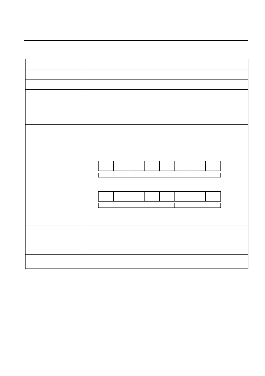
changing this data, clear the I/O assignment data, and switch the power off then on again.
ARC WELD SIGNAL
This data specifies whether arc welding input/output and arc welding stick detection
signals are to be output. If DISABLE (default), the arc welding signals are not transmitted.
Instead, only analog data is transmitted. If ENABLE, the arc welding signals are
transmitted. After changing this data, clear the I/O assignment data, and switch the power
off then on again. If DISABLE, the configuration of the analog data will be as listed in
Table 4--11.
Table 4--11. Data Configuration When Only Analog Inputs are Enabled
bit 7
bit 6
bit 5
bit 4
bit 3
bit 2
bit 1
bit 0
AD15--1 AD14--1 AD13--1 AD12--1 AD11--1 AD10--1 AD09--1 AD08--1
AD07--1 AD06--1 AD05--1 AD04--1 AD03--1 AD02--1 AD01--1 AD00--1
AD15--2 AD14--2 AD13--2 AD12--2 AD11--2 AD10--2 AD09--2 AD08--2
AD07--2 AD06--2 AD05--2 AD04--2 AD03--2 AD02--2 AD01--2 AD00--2
AD00--1 to AD15--1 are data input via analog input data channel 1.
AD00--2 to AD15--2 are data input via analog input data channel 2.
4.3.2
DP MASTER ANALOG
I/O CONFIGURATION

B--81254EN/01
4--20
1. ENTER YOUR CHAPTER TITLE HERE
AD08 to AD15 are the high--order byte, while AD00 to AD07 are the
low--order byte.
Table 4--12. Data Configuration When Only Analog Outputs are Enabled
bit 7
bit 6
bit 5
bit 4
bit 3
bit 2
bit 1
bit 0
DA15--1 DA14--1 DA13--1 DA12--1 DA11--1 DA10--1 DA09--1 DA08--1
DA07--1 DA06--1 DA05--1 DA04--1 DA03--1 DA02--1 DA01--1 DA00--1
DA15--2 DA14--2 DA13--2 DA12--2 DA11--2 DA10--2 DA09--2 DA08--2
DA07--2 DA06--2 DA05--2 DA04--2 DA03--2 DA02--2 DA01--2 DA00--2
DA00--1 to DA15--1 are data output via analog output data channel 1.
DA00--2 to DA15--2 are data output via analog output data channel 2.
DA08 to DA15 constitute the high--order byte, while DA00 to DA07
constitute the low--order byte.
If ENABLE, the configuration of the analog data will be as listed below.
Table 4--13. Data Configuration for Arc Welding Input Signals and Analog
Inputs
bit 7
bit 6
bit 5
bit 4
bit 3
bit 2
bit 1
bit 0
WI08
WI07
WI06
WI05
WI04
WI03
WI02
WI01
WSK
AD15--1 AD14--1 AD13--1 AD12--1 AD11--1 AD10--1 AD09--1 AD08--1
AD07--1 AD06--1 AD05--1 AD04--1 AD03--1 AD02--1 AD01--1 AD00--1
AD15--2 AD14--2 AD13--2 AD12--2 AD11--2 AD10--2 AD09--2 AD08--2
AD07--2 AD06--2 AD05--2 AD04--2 AD03--2 AD02--2 AD01--2 AD00--2
WI01 to WI08 are arc welding input signals. WSK is the welding stick
detection signal.
Table 4--14. Data Configuration for Arc Welding Output Signals and
Analog Outputs
bit 7
bit 6
bit 5
bit 4
bit 3
bit 2
bit 1
bit 0
WO08
WO07
WO06
WO05
WO04
WO03
WO02
WO01
WST
DA15--1 DA14--1 DA13--1 DA12--1 DA11--1 DA10--1 DA09--1 DA08--1
DA07--1 DA06--1 DA05--1 DA04--1 DA03--1 DA02--1 DA01--1 DA00--1
DA15--2 DA14--2 DA13--2 DA12--2 DA11--2 DA10--2 DA09--2 DA08--2
DA07--2 DA06--2 DA05--2 DA04--2 DA03--2 DA02--2 DA01--2 DA00--2
WO01 to WO08 are arc welding output signals. WST is the welding stick
detection signal.
DEVICE 1 to 3 correspond to analog device numbers.
The data of DEVICE 1 specifies data for analog device 1.
The data of DEVICE 2 specifies data for analog device 2.
The data of DEVICE 3 specifies data for analog device 3.
The term analog input indicates an analog input to the R--J3 master, that is,
data output from an analog slave device to the R--J3 master.
The term analog output indicates an analog output from the R--J3 master,
that is, data output from the R--J3 master to an analog device.
B--81254EN/01
4--21
1. ENTER YOUR CHAPTER TITLE HERE
Table 4--15. DP MASTER ANALOG I/O CONFIG Screen(2)
ITEM
Description
AI SLAVE ADDRESS
This data specifies the slave address for an analog input device.*
AO SLAVE ADDRESS
This data specifies the slave address for an analog output device.*
NUMBER OF AI
This data specifies the number of analog input channels.**
NUMBER OF AO
This data specifies the number of analog output channels.**
AI START BIT
An analog input consists of one word per channel. This data specifies the first bit in the
word data to become effective.
AO START BIT
An analog output consists of one word per channel. This data specifies the first bit in the
word data to become effective.
AI VALID/NOVALID BITS
This data specifies the number of valid/no valid bits on a analog input word data. The no
valid bits start from bit0. The valid bits start after the no valid bits. If 13, 3, the valid bits are
13 and the no valid bits are 3. This setting indicates as follows.
bit15
bit14
bit13
bit12
bit11
bit10
bit9
bit8
bit7
bit6
bit5
bit4
bit3
bit2
bit1
bit0
VALID BITS
VALID BITS
NO VALID BITS
(These bits are always 0)
AO VALID/NOVALID BITS
This data specifies the number of valid/no valid bits on a analog output word data. The
representation of this data is the same as AI VALID / NOVALID BITS.
AI OFFSET ADDRESS
This data specifies the first effective analog input data byte in an area dedicated to data
received from a unit having the slave address specified in AI SLAVE ADDRESS.
AO OFFSET ADDRESS
This data specifies the first effective analog output data byte in an area dedicated to data
received from a unit having the slave address specified in AO SLAVE ADDRESS.
*For an analog device having both analog input and output functions, both
of the above data must be set to the same value. For an input--only
analog device, set AO SLAVE ADDRESS to 0. For an output--only
analog device, set AI SLAVE ADDRESS to 0.
**Analog data is represented as a two’s complement. Both of the above
data are default settings to two channels. They can, however, be set up to
6 channels. An attempt to specify more than six channels will result in
only six channels being specified. After changing these data, clear the
I/O assignment data, and switch the power off then on again.
NOTE word = 2 bytes.
B--81254EN/01
4--22
1. ENTER YOUR CHAPTER TITLE HERE
Figure 4--3. Analog Input Data Flow
Data area for analog inputs
to the R--J3 master
Output area for slave
having analog output function
R--J3 Master digital
input data area
Digital
data 1
Digital
data 2
Digital
data 3
Digital
data 4
Analog
data
Analog
data
Analog
data
Digital
data 2
Digital
data 3
R--J3 Master analog
input data area
Figure 4--4. Analog Output Data Flow
Input area for slave
having analog input function
R--J3 Master digital
output data area
Digital
data 1
Digital
data 2
Digital
data 3
Digital
data 4
Analog
data
Data area for analog outputs
from the R--J3 master
Analog
data
Analog
data
Digital
data 2
Digital
data 3
R--J3 Master analog
output data area
B--81254EN/01
4--23
1. ENTER YOUR CHAPTER TITLE HERE
Figure 4--5. R--J3 Analog Input Data Position in Analog Slave Area
AI OFFSET ADDRESS
Output data area for slave device
sending analog data to the R--J3
master
WI
WSK
AI[n]
AI[n+1]
(NUMBER OF AI) * 2
Figure 4--6. R--J3 Analog Output Data Position in Analog Slave Area
AO OFFSET ADDRESS
Input data area for slave device
receiving analog data from the
R--J3 master
WO
WST
AO[n]
AO[n+1]
(NUMBER OF AO) * 2
NOTE ”n” is determined by configuring Analog I/O on Analog I/O
Screen.
B--81254EN/01
4--24
1. ENTER YOUR CHAPTER TITLE HERE
Procedure 4--6
Displaying DP MASTER ANALOG I/O CONFIG Screen
1 Press MENUS.
2 Select I/O.
3 Press F1, [TYPE].
4 Select PROFIBUS.
5 If DP MASTER ANALOG I/O CONFIG Screen is not displayed,
press F3,[OTHER], and select ANALOG I/O. If F3,[OTHER], is not
displayed, press NEXT,>. You can see the following screen.
DP MASTER ANALOG I/O CONFIG
1/32
1 NUMBER OF DEVICE
:
0
2 ARC WELD SIGNAL
: DISABLE
DEVICE 1
3
AI SLAVE ADDRESS
:
0
4
AO SLAVE ADDRESS
:
0
5
AI OFFSET ADDRESS
:
0
6
AO OFFSET ADDRESS
:
0
7
NUMBER OF AI
:
2
8
NUMBER OF AO
:
2
9
AI START BIT
:
3
10
AO START BIT
:
3
11
AI VALID/NOVALID BITS
:
13,
0
12
AO VALID/NOVALID BITS
:
13,
0
DEVICE 2
13
AI SLAVE ADDRESS
:
0
14
AO SLAVE ADDRESS
:
0
15
AI OFFSET ADDRESS
:
0
16
AO OFFSET ADDRESS
:
0
17
NUMBER OF AI
:
2
18
NUMBER OF AO
:
2
19
AI START BIT
:
3
20
AO START BIT
:
3
21
AI VALID/NOVALID BITS
:
13,
0
22
AO VALID/NOVALID BITS
:
13,
0
DEVICE 3
23
AI SLAVE ADDRESS
:
0
24
AO SLAVE ADDRESS
:
0
25
AI OFFSET ADDRESS
:
0
26
AO OFFSET ADDRESS
:
0
27
NUMBER OF AI
:
2
28
NUMBER OF AO
:
2
29
AI START BIT
:
3
30
AO START BIT
:
3
31
AI VALID/NOVALID BITS
:
13,
0
32
AO VALID/NOVALID BITS
:
13,
0
[ TYPE ]
[OTHER ]
>
I/O PROFIBUS-DP
JOINT
10 %
0
6 To change the setting, set the cursor to the item to be set, and enter a
value by using the numeric keys or function keys.
Step

B--81254EN/01
4--25
1. ENTER YOUR CHAPTER TITLE HERE
7 To clear the I/O assignment,
a Press NEXT,>.
b Press F1,CLR_ASG, then the following message is displayed.
”Clear all assignments ?”
c Press F4,YES to clear all I/O assignment.
8 To save all the PROFIBUS--DP setup data to a file,
a Press FCTN.
b Select SAVE. This will save all the PROFIBUS--DP setup data to
the file, PROFIBUS.SV file, on the default device.

5
DIAGNOSTIC DATA OUTPUT BY A
SLAVE COMMUNICATING WITH THE
R--J3 MASTER
B--81254EN/01
This section describes how to determine the cause of problems that may
occur during communication between the R--J3 master and slave.
All diagnostic data received from a slave communicating with the R--J3
master after the R--J3 controller power on is displayed on DP MASTER
DIAGNOSTIC DATA screen. The latest diagnostic data is always on the
top of list. The data on this screen are the status information and you can
not change them.
Table 5--1. DP MASTER DIAGNOSTIC DATA screen
ITEM
Description
VALID
(DIAGNOSTIC DATA VALID)
This data indicates whether the diagnostic data is valid or invalid.
--
TRUE: This diagnostic data is valid.
--
FALSE: This diagnostic data is invalid.
Address
(SLAVE STATION ADDRESS)
Slave station address that has output each diagnostic data.
Station Status 1
The first data of diagnostic data. The detail of this data is as follows.
D
Master Lock
This slave has been parameterized from another master
D
Prm Fault
The received parameter data from the R--J3 Master are different from those which
the DP--Slave has determined.
D
Invalid Slave Response
The received frame from a slave is not plausible response.
D
Not Supported
A function which this slave does not support is requested.
D
Ext Diag
A diagnostic entry exists in the slave specific diagnostic area(Ext_diag_Data).
D
Cfg Fault
The received configuration data from the R--J3 Master are different from those
which the DP--Slave has determined.
D
Station Not Ready
The DP--Slave is not yet ready for data transfer.
D
Station Non Existent
The DP--Slave can not be reached over the line.
5.1
DP MASTER
DIAGNOSTIC DATA

B--81254EN/01
5--2
1. ENTER YOUR CHAPTER TITLE HERE
Table 5--1. (Cont’d) DP MASTER DIAGNOSTIC DATA screen
ITEM
Description
Station Status 2
The second data of diagnostic data. The detail of this data is as follows.
D
Deactivated
The DP--Slave has been marked inactive.
D
Sync Mode
The DP--Slave has received the Sync control command.
D
Freeze Mode
The DP--Slave has received the Freeze control command.
D
WD on
The watchdog control of DP--Slave has been activated.
D
Stat Diag
The DP--Slave is not able to provide valid user data.
D
Prm Req
The DP--Slave should be reparameterized and reconfigured.
Station Status 3
The third data of diagnostic data. The detail of this data is as follows.
D
Ext Diag Overflow
These exists more diagnostic information than specified in Ext_Diag_Data.
Master Address
The address of DP Master is entered which has parameterized this slave.
Ident Number
The manufacturer identifier is given for this slave.
Ext Diag Data BYTES
The byte length of Ext_Diag_Data.
Ext Diag Data 1 -- 26
In this area the DP--Slave can enter its specific diagnostic.
NOTE For details, refer to PROFIBUS STANDARD DIN 19245 Part 1
and Draft Standard DIN 19245 Part 3.
Procedure 5--1
Displaying the DP MASTER DIAGNOSTIC DATA
1 Press MENUS.
2 Select STATUS.
3 Press F1, [TYPE].
4 Select PROFIBUS. The DP Master diagnostic data will be displayed.
See the following screen for an example.
Step

B--81254EN/01
5--3
1. ENTER YOUR CHAPTER TITLE HERE
DP MASTER DIAGNOSTIC DATA
1/64
NO
VALID
Address
Station Status 1
1
TRUE
4
00000000
2
TRUE
4
00000010
3
TRUE
4
00000001
4
FALSE
0
00000000
5
FALSE
0
00000000
6
FALSE
0
00000000
7
FALSE
0
00000000
8
FALSE
0
00000000
9
FALSE
0
00000000
[ TYPE ] DETAIL
STATUS PROFIBUS-DP
JOINT
10 %
1
NOTE The most recent received diagnostic data from a slave is number 1.
5 To display more information about a diagnostic data, press
F2,DETAIL. The detailed diagnostic data screen displays information
specific to the diagnostic data you selected. When you finished
viewing the detailed diagnostic data, press F2,LIST or PREV.

B--81254EN/01
5--4
1. ENTER YOUR CHAPTER TITLE HERE
DP MASTER DIAGNOSTIC DATA 1
1/49
1 DIAGNOSTIC\DATA\VALID
:
TRUE
2 SLAVE STATION ADDRESS
:
4
3 Station Status 1
:
00000000
4
Master Lock
:
OFF
5
Prm Fault
:
OFF
6
Invalid Slave Response :
OFF
7
Not Supported
:
OFF
8
Ext Diag
:
OFF
9
Cfg Fault
:
OFF
10
Station Not Ready
:
OFF
11
Station Non Existent
:
OFF
12 Station Status 2
:
00001100
13
Deactivated
:
OFF
14
Sync Mode
:
OFF
15
Freeze Mode
:
OFF
16
WD on
:
ON
17
Stat Diag
:
OFF
18
Prm Req
:
OFF
19 Station Status 3
:
00000000
20
Ext Diag Overflow
:
OFF
21 Master Address
:
1
22 Ident Number
:
9Fh
23 Ext Diag Data BYTES
:
0
24 Ext Diag Data
1
:
0h
25 Ext Diag Data
2
:
0h
26 Ext Diag Data
3
:
0h
27 Ext Diag Data
4
:
0h
28 Ext Diag Data
5
:
0h
29 Ext Diag Data
6
:
0h
30 Ext Diag Data
7
:
0h
31 Ext Diag Data
8
:
0h
32 Ext Diag Data
9
:
0h
33 Ext Diag Data 10
:
0h
34 Ext Diag Data 11
:
0h
35 Ext Diag Data 12
:
0h
36 Ext Diag Data 13
:
0h
37 Ext Diag Data 14
:
0h
38 Ext Diag Data 15
:
0h
39 Ext Diag Data 16
:
0h
40 Ext Diag Data 17
:
0h
41 Ext Diag Data 18
:
0h
42 Ext Diag Data 19
:
0h
43 Ext Diag Data 20
:
0h
44 Ext Diag Data 21
:
0h
45 Ext Diag Data 22
:
0h
46 Ext Diag Data 23
:
0h
47 Ext Diag Data 24
:
0h
48 Ext Diag Data 25
:
0h
49 Ext Diag Data 26
:
0h
[ TYPE ]
LIST
NEW
OLD
STATUS PROFIBUS-DP
JOINT
10 %
DIAGNOSTIC DATA VALID
6 To display the diagnostic data newer or older than the displayed data:

B--81254EN/01
5--5
1. ENTER YOUR CHAPTER TITLE HERE
a Press F4,NEW, then the diagnostic newer than the displayed data
is displayed.
b Press F5,OLD, then the diagnostic older than the displayed data is
displayed.

6
COMMUNICATION WITH DP MASTER
(CLASS 2)
B--81254EN/01
This section describes the communication with DP Master(Class 2).
The R--J3 DP Master Function supports the full functionality of services
for Master--Master Communication in the Draft Standard PROFIBUS--DP
DIN 19245 Part 3.
The following service are supported by the R--J3 DP Master Function
D
Get_Master_Diag
D
Upload
D
Download
D
Start_Seq
D
End_Seq
D
Act_para_brct
D
Act_Param
Supported services

7
ERROR CODES AND RECOVERY
B--81254EN/01
(ID = 92)
PROF-000 STOP.G System error(n)
Cause:
System error occurs
Remedy: Contact service. Please inform the digit value displayed in parenthesis. This data is needed
to track the problem.
PROF-001 WARN PROFIBUS PCB not installed
Cause:
PROFIBUS PCB is not mounted into the option slot on the backplane in the R--J3 controller.
Remedy: Mount PROFIBUS PCB into the option slot on the backplane in the R--J3 controller.
PROF-002 STOP.G PROFIBUS PCB abnormal(n)
Cause:
When (n) is 1 or 3, system error occurs in the firmware for DP Slave on Profibus PCB.
Remedy: Contact service. Please inform the digit value displayed in parenthesis. This data is
necessary to track the problem.
PROF-003 STOP.G Slave Config data error
Cause:
The configuration data which is expected by R--J3/DP Slave does not match the
configuration data for R--J3/DP Slave which is set by DP Master. While this alarm is active,
BUS FAULT LED of slave side on Profibus PCB is turned on.
Remedy: Change the R--J3 Slave setup data(See Section 4.1.2) to match the above both configuration
data or change the configuration data for R--J3/DP Slave which is set by DP Master. When
the correct data is set, BUS FAULT LED is turned off and RUN LED is turned on.
PROF-004 STOP.G Slave Param data error
Cause:
The parameter data which is expected by R--J3/DP Slave does not match the parameter
data for R--J3 DP Slave which is set by DP Master. While this alarm is active, BUS FAULT
LED of slave side on Profibus PCB is turned on.
Remedy: Change the parameter data (See Section 4.1.2) for R--J3 DP Slave on DP Master. When the
correct data is set, BUS FAULT LED is turned off and RUN LED is turned on.
PROF-005 STOP.G Master Slave Param error(n)
Cause:
The R--J3 DP MASTER slave parameter setting for slave which is specified by (n) is wrong.
The reason for this alarm is explained by the conditional expression. Following abbreviations
for setting data name are used to explain the reason.
NUMBER_IN
INPUT BYTES on DP MASTER SLAVE PARAMETER Screen
NUMBER_OUT
OUTPUT BYTES on DP MASTER SLAVE PARAMETER Screen
IN_OFFSET
INPUT OFFSET ADDRESS on DP MASTER SLAVE PARAMETER Screen
OUT_OFFSET
OUTPUT OFFSET ADDRESS on DP MASTER SLAVE PARAMETER Screen
Following terminologies are used to explain the reason.
DI byte number
INPUT BYTES on DP MASTER SETUP Screen
DO byte number
OUTPUT BYTES on DP MASTER SETUP Screen
PROF Error Codes

B--81254EN/01
7--2
1. ENTER YOUR CHAPTER TITLE HERE
Total byte number of analog output data and weld output signal data is calculated as follows.
In conditional expression, AO byte number means this data.
If ARC WELD SIGNAL on DP MASTER ANALOG I/O CONFIG Screen is DISABLE,
analog output byte number is NUMBER OF AO on DP MASTER ANALOG I/O CONFIG
Screen * 2.
If ARC WELD SIGNAL is ENABLE, analog output byte number is NUMBER OF AO * 2 +
2
AO_OFFSET
AO OFFSET ADDRESS on DP MASTER ANALOG I/O CONFIG Screen. The
data of NUMBER OF AO and AO OFFSET ADDRESS should be used the same
DEVICE number in AO SLAVE ADDRESS which stores address number (n).
Total byte number of analog input data and weld input signal data is calculated as follows.
In conditional expression, AI byte number means this data.
If ARC WELD SIGNAL on DP MASTER ANALOG I/O CONFIG Screen is DISABLE,
analog
input byte number is NUMBER OF AI on DP MASTER ANALOG I/O CONFIG Screen * 2.
If ARC WELD SIGNAL is ENABLE, analog input byte number is NUMBER OF AI * 2 + 2
AI_OFFSET
ADDRESS on DP MASTER ANALOG I/O CONFIG Screen.
The data of NUMBER OF AI and AI OFFSET ADDRESS should be used the
same DEVICE number in AI SLAVE ADDRESS which stores address number (n).
When one of the following conditions is satisfied, this alarm occurs.
a) DI byte number < NUMBER_IN + IN_OFFSET
b) DO byte number < NUMBER_OUT + OUT_OFFSET
c) NUMBER_IN
< AI_OFFSET + AI byte number
d) DI byte number < NUMBER_IN -- AI byte number + IN_OFFSET
e) NUMBER_OUT < AO_OFFSET + AO byte number
f) DO byte number < NUMBER_OUT -- AO byte number + OUT_OFFSET
Remedy: Change the R--J3 DP MASTER setup data not to satisfy the above conditional expressions.
PROF-006 STOP.G Another Master Lock(n)
Cause:
In case that R--J3 is DP Master, R--J3 checks the status of its DP Slave,
DP Slave, with address showed by (n) is already parameterized by the other
DP Master. ”n”in (n) means the address of slave. Please refer to Diag.Master_lock
of Station_status_1 in 8.3.1 of Draft Standard PROFIBUS--DP DIN 19245 Part3
in detail.
Remedy: Please modify the setting so that DP Slave with the address showed by (n), connected with
R--J3 DP Master is not parameterized by the other DP Slave.
PROF-007 STOP.G Parameter Fault(n)
Cause:
In case that R--J3 is DP Master, R--J3 checks the status of its DP Slave, the parameter part
of slave parameter set on DP MASTER SLAVE PARAMETER screen connect with DP Slave
with address showed by (n), is incorrect. Please refer to the description about
Diag.Prm_Fault of Station_status_1 in 8.3.1 of Draft Standard PROFIBUS--DP DIN 19245
Part3 in detail.
Remedy: Please modify the parameter part of slave parameter set. Please refer to the manual of DP
Slave or consult the manufacturer.

B--81254EN/01
7--3
1. ENTER YOUR CHAPTER TITLE HERE
PROF-008 STOP.G Invalid Slave Response(n)
Cause:
In case that R--J3 is DP Master, R--J3 checks the status of its DP Slave, it received the
invalid response from DP Slave with address showed by (n). Please refer to the description
of Diag.Invalid_Slave_Response of Station_status_1 in 8.3.1 of Draft Standard
PROFIBUS--DP DIN 19245 Part3 in detail.
Remedy: Please confirm the status of the corresponding DP Slave. Please the manual of DP Slave or
consult the manufacturer.
PROF-010 STOP.G Config Fault(n)
Cause:
In case that R--J3 is DP Master, R--J3 checks the status of its DP Slave, the configuration
part of slave parameter set on DP MASTER SLAVE PARAMETER to connect with DP Slave
with address showed by (n) is incorrect. Please refer to the description about Diag.Cfg_Fault
of Station_status_1 in 8.3.1 of Draft Standard PROFIBUS--DP DIN 19245 Part3 in detail.
Remedy: Please modify configuration part of slave parameter set. Please refer to the manual of DP
Slave or consult the manufacturer.
PROF-011 STOP.G Slave not ready(n)
Cause:
In case that R--J3 is DP Master, R--J3 checks the status of its DP Slave, DP Slave with
address showed by (n) is not yet ready for data transfer. Please refer to the description
about Diag.Station_Not_Ready of Station_status_1 in 8.3.1 of Draft Standard
PROFIBUS--DP DIN 19245 Part3 in detail.
Remedy: Please adjust the corresponding DP Slave so as to be ready for data transfer before
receiving the request for data transfer from DP Master to the DP Slave.
PROF-012 STOP.G Slave not existent(n)
Cause:
In case that R--J3 is DP Master, R--J3 checks the status of its DP, Slave DP Slave with
address showed by (n) has not connected with network or is not powered on. Please refer to
the description about Diag.Station_Non_Existent of Station_status_1 in 8.3.1 of Draft
Standard PROFIBUS--DP DIN 19245 Part3 in detail.
Remedy: Please connect the corresponding DP Slave with network or turn it on.
PROF-013 STOP.G CMI error(code = n)
Cause:
There is a contradiction between the robot controller software and the DP Master software on
the PROFIBUS board. The detail is shown by the sub error code n as follows.
Code No.
Description
7
Unrecoverable error occurred in the PROFIBUS board DP Master software.
8
The initialize data in the common memory interface are invalid.
10
There is no response from the DP Master software on the PROFIBUS board.
1. PROFIBUS board is broken.
11
Controller type and version of the DP Master software are not compatible.
12
The layer is not correct when the robot controller software issues a service request to the DP Master
software on the PROFIBUS board.
13
The service ID is not correct, when the robot controller software issues a service request to the DP
Master software on the PROFIBUS board.
14
The service primitive is not correct, when the robot controller software issues a service request to the DP
Master software on the PROFIBUS board.
15
Lack of the data block memory in the common memory interface on the PROFIBUS board.
16
Communication reference is invalid.
19
Routine call for the common memory interface is invalid.

B--81254EN/01
7--4
1. ENTER YOUR CHAPTER TITLE HERE
Code No.
Description
20
Error occurred in the common memory interface.
21
There is no available memory space on the PROFIBUS board.
22
The service request was issued before receiving the response of the previous service request.
23
The DP Master software process on the PROFIBUS board overran.
24
Unsupported service request was issued from robot controller software to the DP Master software on the
PROFIBUS board.
25
The service request which was issued from robot controller software was not executed by DP Master
software on the PROFIBUS board.
Remedy: Contact service except the following 2 sub error codes. Please inform the digit value
displayed in parenthesis. This data is needed to track the problem.
Code No.
Description
10
Exchange the PROFIBUS board.
23
Turn off and on the robot controller. Record error and contact service when this error occurs frequently.
PROF-014 STOP.G DP error(code = n)
Cause:
DDLM--Function Call error occurred on the PROFIBUS board DP Master software. The sub
error code n means the following status value. Please refer to the section 8.2 Description
Format of DDLM--Function Calls in the document ”Draft Standard PROFIBUS--DP DIN 19245
Part3”for details.
Code No.
Status value
Description
1
UE
Remote--DDLM/FDL interface error
2
RR
Resources of the remote--FDL Entity not sufficient or not available
3
RS
Service or remote--address at remote--LSAP or remote--LSAP not activated;
--
remote--station is no DP--Station
--
remote--station is not yet ready for these functions
--
remote--station is associated with an other Requestor
--
optional service not available
4
RA
Access of remote--SAP blocked
17
NA
Negative ack, no reaction from remote station
18
DS
Local--FDL/PHY Entity is not possible
19
NO
Service in this state not possible
20
LR
Local resource not available
21
IV
Invalid parameters in request
22
TO
Function--Timeout expired
193
FE
Format--Error in a Request--frame
194
NI
Function not implemented
195
AD
Access denied
196
EA
Area too large (Up--/Download)
197
LE
Data--block--length too large (Up--/Download)
198
RE
Format--Error in a Response--frame
199
IP
Invalid Parameter
200
SC
Sequence Conflict
201
SE
Sequence Error
202
NE
Area non--existent

B--81254EN/01
7--5
1. ENTER YOUR CHAPTER TITLE HERE
Code No.
Description
Status value
203
DI
Data Incomplete
204
NC
Master parameter set not compatible
Remedy: Please refer to the section 8.2 Description Format of DDLM--Function Calls in the document
”Draft Standard PROFIBUS--DP DIN 19245 Part3”.
PROF-015 STOP.G DP sub error(code = n)
Cause:
DDLM--Function Call error occurred in the DP Master software on the PROFIBUS board. This
alarm message is supplement of ”PROF--014 DP error”. The detail is shown by the sub error
code n as follows.
Code No.
Description
1
Data alignment problem occurred.
2
Too many DP Slaves are connected.
3
Slave address is incorrect.
4
Specified address assign mode is not supported.
5
Too short diagnostic data.
6
Parameter data length in the slave parameter set is invalid.
7
Configuration data length in the slave parameter set is invalid.
8
Diagnostic data length is invalid.
9
Bus parameter length is invalid.
10
Slave parameter length is invalid.
11
I/O data length is invalid.
12
Memory area for the DP Master software on the PROFIBUS board is insufficient.
13
Operation mode of the DP Master software on the PROFIBUS board is not correct.
14
DP Slave denied the access.
15
The area code of the service request from robot controller to DP Master software on the PROFIBUS
board is invalid.
16
The service request from robot controller to the DP Master software on the PROFIBUS board is not
supported.
17
The parameter part in the slave parameter set for the DP Master software on the PROFIBUS board is
invalid.
18
The configuration data part in the slave parameter set for the DP Master software on the PROFIBUS
board is invalid.
19
The address assignment table in the slave parameter set for the DP Master software on the PROFIBUS
board is invalid.
20
The slave user data part in the slave parameter set for the DP Master software on the PROFIBUS board
is invalid.
21
The slave parameter set for DP Master software on the PROFIBUS board is invalid.
22
Cannot access the specified area.
23
The baud rate value in the bus parameter set for DP Master software on the PROFIBUS board is invalid.
24
The BP flag value in the bus parameter set for DP Master software on the PROFIBUS board is invalid.
25
FDL state is invalid when robot controller issues a service request to the DP Master software on the
PROFIBUS board.
26
Specified activation is invalid when robot controller issues a service request to the DP Master software
on the PROFIBUS board.
27
Master station address in the bus parameter set is invalid.
28
DPRAM initialization error occurred in DP Master software on the PROFIBUS board.

B--81254EN/01
7--6
1. ENTER YOUR CHAPTER TITLE HERE
Code No.
Description
29
Specified data length is not correct when robot controller issues a service request to the DP Master
software on the PROFIBUS board.
31
Specified identifier is invalid when robot controller issues a service request to the DP Master software on
the PROFIBUS board.
Remedy: Contact service except the following 12 sub error codes. Please inform the digit value
displayed in parenthesis. This data is needed to track the problem.
Code No.
Description
2
The number of the DP Slaves must be equal to or less than 32.
3
Set a correct slave address.
13
Issue a correct service request in the correct operation mode. If any slave parameter is downloaded into
robot controller, the operation mode can be changed to CLEAR or OPERATE. If no slave parameter is
downloaded into robot controller, the operation mode stays in the STOP. Pay attention to the above
description when DP Master class2 issues service requests.
14
Confirm the status of the DP Slave device.
17
The parameter part in the slave parameter set are downloaded from DP Master
class2 or R--J3 DP Master class1.
1 Confirm the parameter part from the DP Master class2 is correct, when they are downloaded from
DP Master class2.
2 Confirm the values in the following items on DP MASTER SLAVE PARAMETER Screen are correct.
STATION STATUS
D
LOCK REQ
D
UNLOCK REQ
D
SYNC REQ
D
FREEZE REQ
D
WD REQ
WD FACT1
WD FACT2
MIN TSDR
IDENT NUMBER
GROUP IDENT
D
GROUP 1
D
GROUP 2
D
GROUP 3
D
GROUP 4
D
GROUP 5
D
GROUP 6
D
GROUP 7
D
GROUP 8
USER PRM DATA BYTES
USER PRM DATA
18
The configuration data part in the slave parameter set are downloaded from
DP Master class2 or R--J3 DP Master class1.
1 Confirm the configuration data part from the DP Master class2 is correct, when they are downloaded
from DP Master class2.
2 Confirm the values in the following items on DP MASTER SLAVE PARAMETER
Screen are correct.
CONFIG DATA BYTES
CONFIG DATA
19
The address assignment table in the slave parameter set are downloaded from
DP Master class2 or R--J3 DP Master class1.
1 Confirm the address assignment table from the DP Master class2 is correct, when they are downloaded
from DP Master class2.
2 Confirm the values in the following items on DP MASTER SLAVE PARAMETER Screen are correct.
INPUT BYTES
OUTPUT BYTES
DPRAM INPUT OFFSET
DPRAM OUTPUT OFFSET

B--81254EN/01
7--7
1. ENTER YOUR CHAPTER TITLE HERE
Code No.
Description
20
The slave user data part in the slave parameter set are downloaded from DP
Master class2 or R--J3 DP Master class1.
1 Confirm the slave user data part from the DP Master class2 is correct, when they are downloaded from
DP Master class2.
2 Confirm the values in the following items on DP MASTER SLAVE PARAMETER Screen are correct.
SLAVE USER DATA BYTES
SLAVE USER DATA
21
The slave parameter set is downloaded from DP Master class2 or R--J3 DP Master class1.
1 Confirm the slave parameter set from the DP Master class2 is correct, when they are downloaded from
DP Master class2.
2 Confirm the values in the following items on DP MASTER SLAVE PARAMETER Screen are correct.
SLAVE FLAG
D
ACTIVE
D
NEW PRM
SLAVE TYPE
23
The baud rate value in the bus parameter set is downloaded from DP Master class2
or R--J3 DP Master class1.
1 Confirm the baud rate value in the bus parameter set from the DP Master class2 is correct, when it is
downloaded from DP Master class2.
2 Confirm the value of Baudrate on DP MASTER BUS PARAMETER screen is correct.
24
The BP flag value in the bus parameter set is downloaded from DP Master class2 or R--J3 DP Master
class1.
1 Confirm the BP flag value in the bus parameter set from the DP Master class2 is correct, when it is
downloaded from DP Master class2.
2 Confirm the BP Flag value on DP MASTER BUS PARAMETER Screen is correct.
27
The master station address of this robot in the bus parameter set is downloaded from DP Master class2
or R--J3 DP Master class1.
1 Confirm the master station address in the bus parameter set from the DP Master class2 is correct, when
it is downloaded from DP Master class2.
2 Confirm the FDL Add value on DP MASTER BUS PARAMETER Screen is correct.
PROF-016 STOP.G Slave communication stop
Cause:
1. Some error occurred in the DP Slave software on the PROFIBUS board.
2. The version of the DP Slave software on the PROFIBUS board is old.
Remedy: 1. Record error and contact service.
2. Replace the DP Slave software on the PROFIBUS board to the new one.
PROF-017 STOP.G Slave disconnected
Cause:
1. The cable of the DP Slave on the PROFIBUS board in R--J3 controller is disconnected.
2. The communication to the DP Master is disconnected.
Remedy: 1. Reconnect the cable or replace the broken wire.
2. Confirm that the DP Master station is alive so that it can communicate with the DP Slave.

B--81254EN/01
7--8
1. ENTER YOUR CHAPTER TITLE HERE
PROF-018 STOP.G Exist specific diag(n)
Cause:
In case that R--J3 is DP Master, R--J3 checks the status of its DP Slave, a status message
exists in the slave specific diagnostic area in the received diagnostic data. This diagnostic
data is sent from DP Slave with address showed by (n). Please refer to the description about
Diag.Ext_Diag of Station_status_1 in 8.3.1 of Draft Standard PROFIBUS--DP DIN 19245
Part3 in detail.
Remedy: Please refer to the manual of DP Slave or consult the manufacturer to investigate the
specific diagnostic data.

A
GSD File for R--J3 PROFIBUS--DP Slave
B--81254EN/01
A--1
;======================================================
; FANUC ROBOT DP Slave 12M
/SPC3
; Date : 13.07.99
;======================================================
;
#Profibus_DP
Vendor_Name = ”FANUC”
Model_Name = ”FANUC ROBOT”
Revision = ”1.0”
Ident_Number = 0x009F
Protocol_Ident = 0
Station_Type = 0
FMS_supp = 0
Hardware_Release = ”1.00”
Software_Release = ”1.00”
9.6_supp = 1
19.2_supp = 1
93.75_supp = 1
187.5_supp = 1
500_supp = 1
1.5M_supp = 1
3M_supp = 1
6M_supp = 1
12M_supp = 1
MaxTsdr_9.6 = 60
MaxTsdr_19.2 = 60
MaxTsdr_93.75 = 60
MaxTsdr_187.5 = 60
MaxTsdr_500 = 100
MaxTsdr_1.5M = 150
MaxTsdr_3M = 250
MaxTsdr_6M = 450
MaxTsdr_12M = 800
Redundancy = 0
Repeater_Ctrl_Sig = 2
24V_Pins = 0
;
; Slave specific parameters
;
Freeze_Mode_supp = 0
Sync_Mode_supp = 0
Auto_Baud_supp = 1
Set_Slave_Add_supp = 0
User_Prm_Data_Len = 0
Min_Slave_Intervall = 1
Modular_Station = 0
;
Module = ”8 Byte Out, 10 Byte In” 0xC0,0x07,0x09
EndModule
;

B
GSD File for R--J3 PROFIBUS--DP Master
B--81254EN/01
B--1
;*****************************************************************************
;
; FANUC ROBOT DP Master Class 1
; Date : 13.07.99
;
;*****************************************************************************
#Profibus_DP
Vendor_Name
= ”FANUC”
Model_Name
= ”FANUC ROBOT”
Revision
= ”1.00”
Ident_Number
= 0x00A2
Protocol_Ident
= 0
Station_Type
= 1
FMS_supp
= 0
Hardware_Release = ”1.00”
Software_Release = ”1.00”
9.6_supp
= 1
19.2_supp
= 1
93.75_supp = 1
187.5_supp = 1
500_supp
= 1
1.5M_supp
= 1
3M_supp
= 1
6M_supp
= 1
12M_supp
= 1
MaxTsdr_9.6
= 60
MaxTsdr_19.2
= 60
MaxTsdr_93.75 = 60
MaxTsdr_187.5 = 60
MaxTsdr_500
= 100
MaxTsdr_1.5M
= 150
MaxTsdr_3M
= 250
MaxTsdr_6M
= 450
MaxTsdr_12M
= 800
Redundancy
= 0
Repeater_Ctrl_Sig = 2
24V_Pins
= 0
Download_supp
= 1
Upload_supp
= 1
Act_Para_Brct_supp = 1
Act_Param_supp
= 1
Max_MPS_Length
= 65532
Max_Lsdu_MS
= 244
Max_Lsdu_MM
= 244

B. GSD File for R--J3 PROFIBUS--DP Master
B--81254EN/01
B--2
Min_Poll_Timeout
= 1000
Trdy_9.6
= 11
Trdy_19.2
= 11
Trdy_93.75 = 11
Trdy_187.5 = 11
Trdy_500
= 11
Trdy_1.5M
= 11
Trdy_3M
= 11
Trdy_6M
= 11
Trdy_12M
= 11
Tqui_9.6
= 0
Tqui_19.2
= 0
Tqui_93.75 = 0
Tqui_187.5 = 0
Tqui_500
= 0
Tqui_1.5M
= 0
Tqui_3M
= 3
Tqui_6M
= 6
Tqui_12M
= 9
Tset_9.6
= 1
Tset_19.2
= 1
Tset_93.75 = 1
Tset_187.5 = 1
Tset_500
= 1
Tset_1.5M
= 1
Tset_3M
= 4
Tset_6M
= 8
Tset_12M
= 16
LAS_Len
= 32
Tsdi_9.6
= 70
Tsdi_19.2
= 70
Tsdi_93.75 = 70
Tsdi_187.5 = 70
Tsdi_500
= 150
Tsdi_1.5M
= 200
Tsdi_3M
= 250
Tsdi_6M
= 450
Tsdi_12M
= 800
Max_Slaves_supp = 32
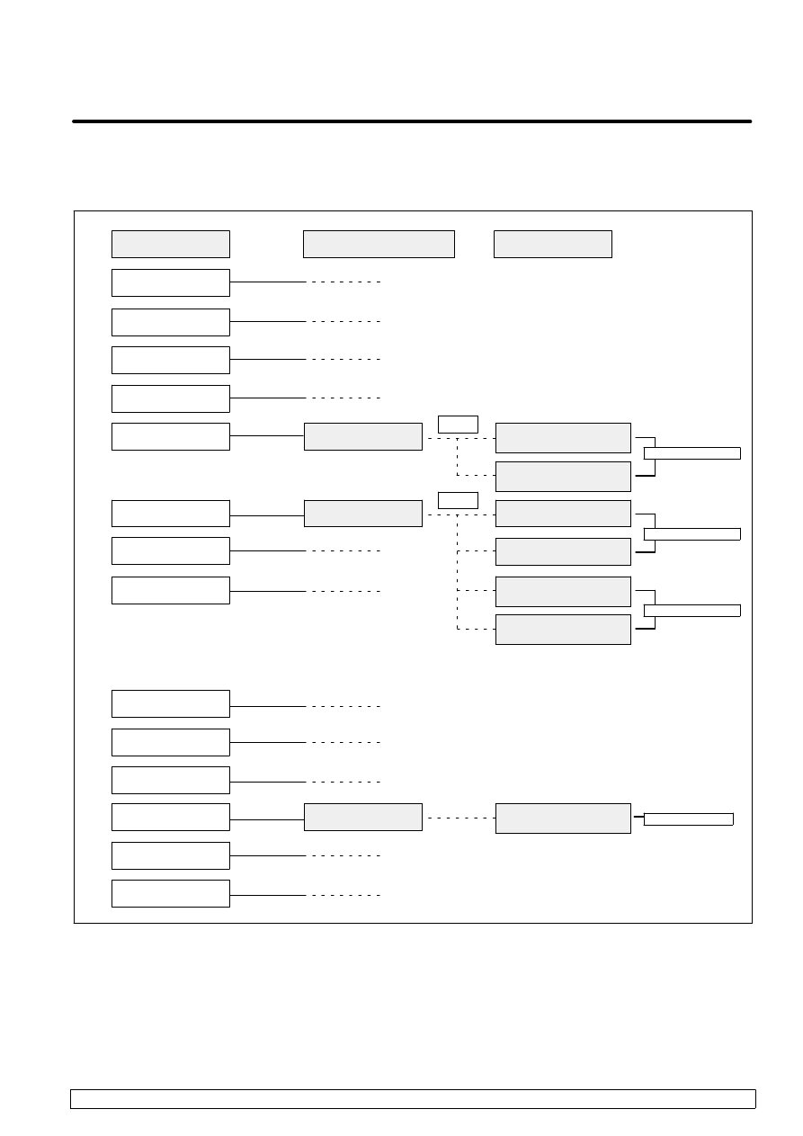
C
MENU Map for R--J3 PROFIBUS--DP Interface
Function
B--81254EN/01
C--1
There are the following screens for R--J3 PROFIBUS--DP Interface
Function.
Figure C--1. Screens for R--J3 PROFIBUS--DP interface function
F3
See Section 4.3.
See Section 4.1.
See Section 4.2.
See Chapter 5.
F3
Screen Menu*
UTILITIES
MANUAL FCTNS
TEST CYCLE
ALARM
SETUP
FILE
USER
SELECT
EDIT
DATA
STATUS
POSITION
SYSTEM
I/O
Screen Change Menu**
PROFIBUS
PROFIBUS
PROFIBUS
Screen
DP MASTER
DIAGNOSTIC DATA
DP MASTER
DIGITAL I/O CONFIG
DP SLAVE SETUP
DP MASTER SETUP
DP MASTER
BUS PARAMETER
DP MASTER
SLAVE PARAMETER
DP MASTER
ANALOG I/O CONFIG
* To display the screen menu, press the MENUS key on teach pendant. And then select the item with arrow key
and press ENTER key.
** To display the screen change menu, press the F1, [TYPE].
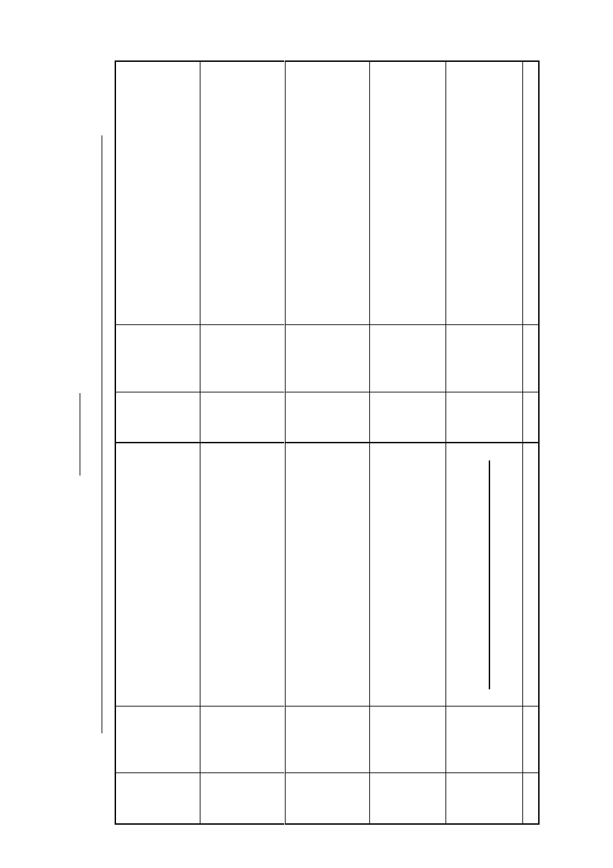
R
ev
is
io
n
R
ec
o
rd
FA
N
U
C
R
o
b
o
t
se
ri
es
(
R
--J
3
C
O
N
T
R
O
L
L
E
R
)
P
R
O
F
IB
U
S
--D
P
(1
2M
)
In
te
rf
ac
e
F
u
n
ct
io
n
O
P
E
R
A
TO
R
’S
M
A
N
U
A
L
(B
--8
12
54
E
N
)
01
N
ov
.,
’9
9
R
ev
is
io
n
D
at
e
C
on
te
nt
s
R
ev
is
io
n
D
at
e
C
on
te
nt
s

D
No part of this manual may
be reproduced in any form.
D
All specifications and designs
are subject to change without
notice.

O ct . , 1 9 9 9
FA N U C LT D
Pri n t e d i n Ja p a n
Wyszukiwarka
Podobne podstrony:
instrukcja profibus
Basic information on PROFIBUS h1112g
Profibus EP 12 2009
Interfejsy szeregowe RS232, PROFIBUS
PROFIBUS
Przemysłowa sieć Profibus
Profibus informacje
Komunikacja PROFIBUS, S7 200, S7 300(1)
Interface szeregowy PROFIBUS
Porównanie FF z ProfibusPA
profibus
787 W06 Profibus id 46028 Nieznany
instrukcja profibus
02 AUMA ba sar1 07 16 ac1 profibus pl
R J2 Controller Profibus DP Operator Manual [B 80844EN 03]
więcej podobnych podstron