Steerprop
TECHNICAL INFORMATION
DESIGNERS' CHECKLIST No. 2
Offshore Support Vessels

2/2001
April 2001
DESIGNERS’ CHECKLIST Nº 2
Offshore Support Vessels
TABLE OF CONTENTS
HULL FORM
1.
Stern Lines .................................................................................................. 1
2.
Hard Chine .................................................................................................. 2
3.
Round Bilge................................................................................................. 2
4.
Transom ...................................................................................................... 2
SKEG
5.
Skeg Size .................................................................................................... 3
WEIGHT, HYDROSTATIC, STABILITY
6.
Weight......................................................................................................... 4
7.
Trim and Draft.............................................................................................. 4
HULL STRENGTH
8.
Mounting Adapters....................................................................................... 4
9.
Navigation Mast........................................................................................... 5
10.
Shaft Bearing Support.................................................................................. 5
11.
Bulwark ....................................................................................................... 5
12.
Skeg............................................................................................................ 5
PROPULSOR INSTALLATION
13.
Propulsor Installation Alternatives................................................................. 5
14.
Distance between the Propulsor Units .......................................................... 7
15.
Propulsor Tilting and Heeling........................................................................ 8
INTERMEDIATE SHAFTS
16.
Shaft Arrangement....................................................................................... 9
17.
Shaft Angle................................................................................................ 12
18.
Cardan Joint Phasing................................................................................. 13
CONTROL LAYOUT
19.
Control Layout ........................................................................................... 13
PROPULSOR ROOM SPACE
20.
Propulsor Room Space .............................................................................. 14
MAIN ENGINE
21.
Main Engine Choice .................................................................................. 14
EXTERNAL CONNECTIONS
22.
Electricity................................................................................................... 14
23.
Cabling...................................................................................................... 14
24.
External Tanks........................................................................................... 15
25.
Cooling...................................................................................................... 15
2/2001
April 2001
DESIGNERS’ CHECKLIST Nº 2
Offshore Support Vessels
This “checklist” is compiled in order to enable designers with no or little experience in
azimuth propulsion vessels to make significantly better preliminary designs and proposals
for azimuth propulsion vessels. The list can also well serve the experienced designer as a
checklist or reminder that important aspects have been considered in the design.
The list is based on a the experience of supporting naval architects, shipyards and owners
with comments, hints and suggestions on how to improve their designs in order to optimise
the available performance of vessels equipped with azimuth propulsion. When compiling
the list we have also used direct input from naval architects on what is special on vessels
with azimuth propulsion and what should be kept in mind when designing these kinds of
vessels.
The list is in no way exhaustive and does not include every important aspect of a good
azimuth propulsor vessel design. It is more to be seen as a reminder to details often not
known, forgotten or ignored.
The advice and details in the list should not be taken as requirements, nor can a vessel be
designed solely relying on the items in this list – the real work, and end result is still up to
the naval architect designing the vessel, as is the full responsibility. Steerprop Ltd. cannot
be held responsible for any possible negative influence on any design based on the
proposals in this list.
HULL FORM
1.
Stern Lines
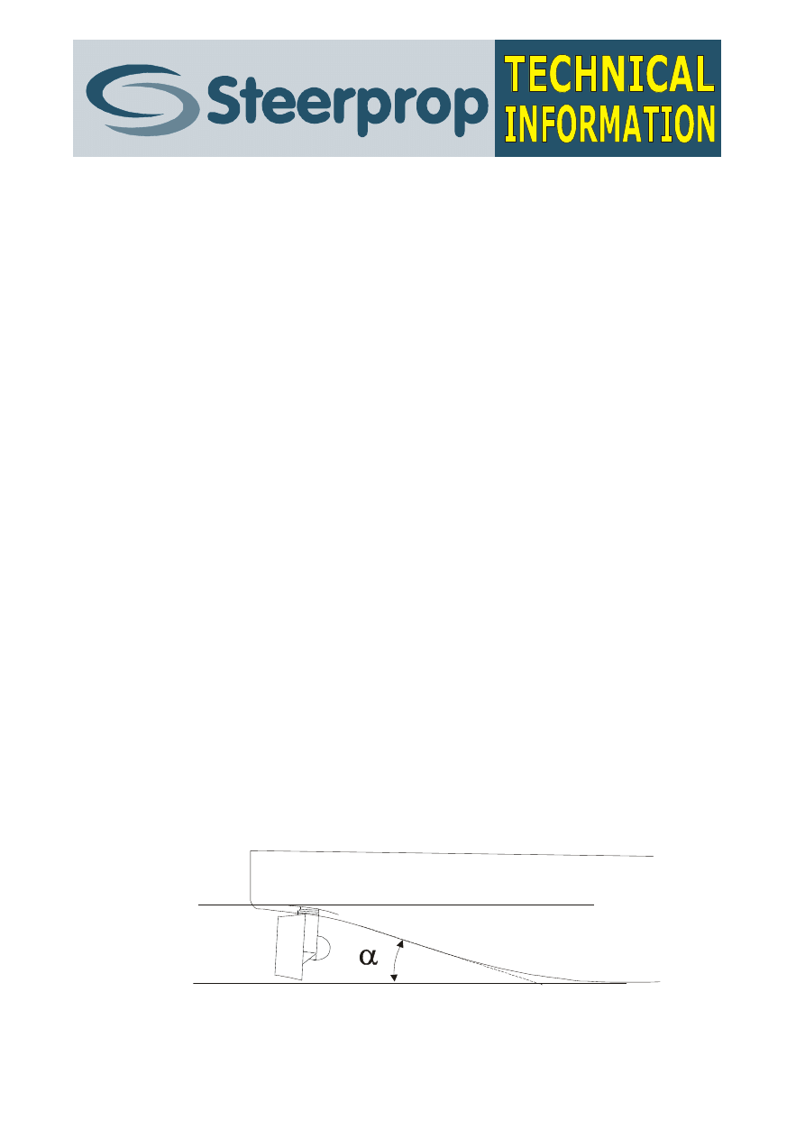
Offshore support vessels with azimuth propulsors should be designed with
a “buttock flow” or - also called, “pram-type” – stern, where the water
inflow to the propellers is mainly along the buttocks, not from the sides.
The angle between the baseline and the buttocks in the stern should be
kept as small as possible. A good rule-of-thumb for maximum
recommended angle is 13º + 1º for each meter of immersion (hull draft).
Thus, the angle should normally be kept less than 17º …18º (fig. 1).
Fig.1.
Profile of a buttock flow stern. Maximum recommended angle a is 13º + 1º for each meter
of draft

2/2001
April 2001
DESIGNERS’ CHECKLIST Nº 2
Offshore Support Vessels
2
Larger angles will cause the water flow to separate and cause turbulence
in front of the propeller, as well as water inflow from the sides – both of
which are prone to decrease propeller performance drastically.
The stern profile is often S-formed, but there is neither need nor benefit in
this neither in straightening the buttocks to be almost horizontal in way of
the propulsors.
The stern should, however, have a slight V-angle all the way to the
transom. There is no need for flattening the area in way of the propulsors.
A V-angle – even a slight one – will reduce the risk for stern slamming in
waves.
The propulsors may protrude below base line, as on some designs they do.
This should also be considered in the skeg dimensions.
2.
Hard Chine
Hard chine designs are possible, but only double chine type is
recommended. Alignment of the chine needs special attention, as flow
separation may occur where flow-lines cross the chine. This increases the
resistance and deteriorates the operating conditions for the propeller,
reducing the performance of the vessel correspondingly.
The double chine should extend all the way to the transom.
3.
Round Bilge
From the hydrodynamic point of view the best bilge form is a round bilge,
with a radius growing towards the stern.
4.
Transom
The transom should be designed with as little immersion as possible, as
the water “trapped” behind the transom causes a large increase in
resistance.
An immersed transom may be “cut off” at approximately 45º to the
waterline in way of the waterline in order to improve astern performance,
fig. 2. A cut off will have a substantial influence on both astern speed and
astern manoeuvrability.
The propulsor should not be installed too close to the transom in order to
avoid ventilation of the propeller while going astern or braking.
2/2001
April 2001
DESIGNERS’ CHECKLIST Nº 2
Offshore Support Vessels
3
Fig. 2. A transom “cut-off”, as shown above, will improve the astern performance substantially
SKEG
5.
Skeg Size
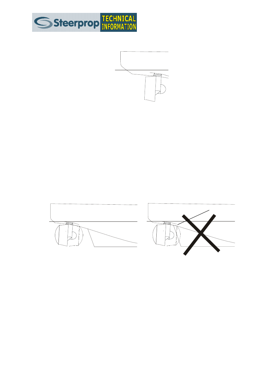
The skeg can normally be very small without losing the directional
stability. A short skeg will make the vessel more manoeuvrable and will
improve astern course keeping and performance. In no case should the
skeg run all the way to the propulsors, when turned for astern sailing, fig.
3. A too long skeg will also make sidestepping difficult as the water flow
from the propulsor is re-directed by skeg.
Fig. 3. Maximum skeg length shown in the left figure. The right figure shows a too long skeg.
The draft of the skeg should preferably be large enough to go below the
azimuth propulsors by 100…300mm. However, dry-docking procedures
should be taken into account, especially when the propulsion units are
protruding below the bottom of the hull.
2/2001
April 2001
DESIGNERS’ CHECKLIST Nº 2
Offshore Support Vessels
4
WEIGHT, HYDROSTATICS, STABILITY
6.
Weight
The weight of the azimuth propulsors may come as a surprise and often it
will be difficult to get a proper balance, if not accounted for in the basic
design. The units are way back in an area with little or no hull volume.
Hence, the centre of gravity for the rest of the vessel needs to be kept
more forward than on similar vessels with conventional propulsion.
7.
Trim and Draft
It should be possible to alter at least the trim in order to improve the
performance and to prevent ventilation of the propellers in waves or when
braking or when running astern. Supply vessels may be required to have
ample ballast tanks in order to compensate for cargo and to improve the
performance of the empty vessel.
HULL STRENGTH
8.
Mounting Adapters
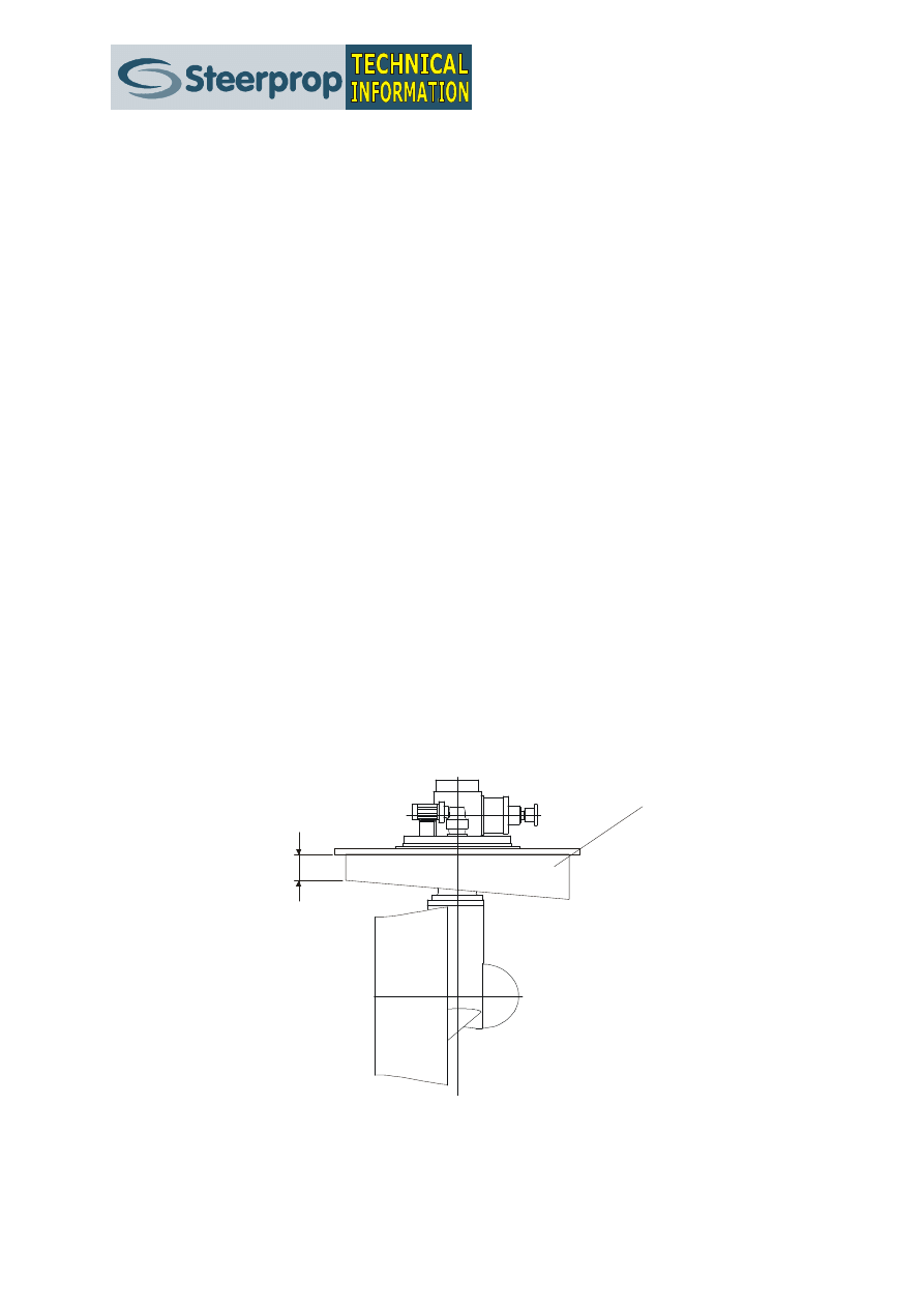
Minimum recommended mounting adapter height is 300 …500 mm at the
lowest point, depending on size and form, fig. 4. Minimum height is
determined by strength requirements and installation procedure.
min. 300 mm
Mounting adapter
Fig. 4.
A drawing showing the mounting adapter and its minimum height.
The hull in way of the azimuth propulsors may require extra strength to
accomplish the correct sequence of damage, i.e. the propulsor should
break before tearing off the bottom.

2/2001
April 2001
DESIGNERS’ CHECKLIST Nº 2
Offshore Support Vessels
5
9.
Navigation Mast
The mast needs to be stiff enough and possibly supported to reduce
excessive vibrations, especially in fast manoeuvres at high speed.
10.
Shaft Bearing Supports
The shaft bearing supports need to be stiff and strong enough to take the
load of the rotating shaft.
11.
Bulwark
The bulwark should be inclined inwards to prevent it from touching when
close to other vessels. Ideally the bulwark should not be as far to the sides
as possible, but some tens of centimetres inwards to enable easy stepping
onboard without having to jump the bulwark first.
The bulwark around aft deck need to be strong enough to take the whole
weight of the tow wire without shearing, if the vessel is equipped with an
aft winch and intended also for towing.
12.
Skeg
The skeg need to be supported inside the hull, not just welded to the
bottom plate. A “soft” skeg may cause severe vibration throughout the
vessel, not only to the skeg itself. The vessel is also supported by the skeg
during dry-docking and it is the first part to hit the bottom in case of
grounding, thus protecting the propeller nozzles.
PROPULSOR INSTALLATION
13.
Propulsor Installation Alternatives
The Steerprop propulsors may be installed in several different
configurations and variations thereof. Additional, customized installation
configurations can also be arranged. The main installation modes are:
•
Weld-in installation
•
Small bolt-in mounting cone
•
Large mounting adapter for thru-hull mounting
2/2001
April 2001
DESIGNERS’ CHECKLIST Nº 2
Offshore Support Vessels
6
Weld-in Installation
The weld in installation is the strongest installation into the hull and the
propulsor is an integrated part of the hull structure. The propulsor is
usually installed in two parts – the upper part, that is welded into the hull,
from above and the lower part from below the hull.
Fig. 5.
Weld-in installation: 1) the upper part is installed from above; 2) the upper part is welded at
the hull bottom and at the top flange, the lower part is brought into place from below the
hull; 3) the lower part is bolted to the upper part
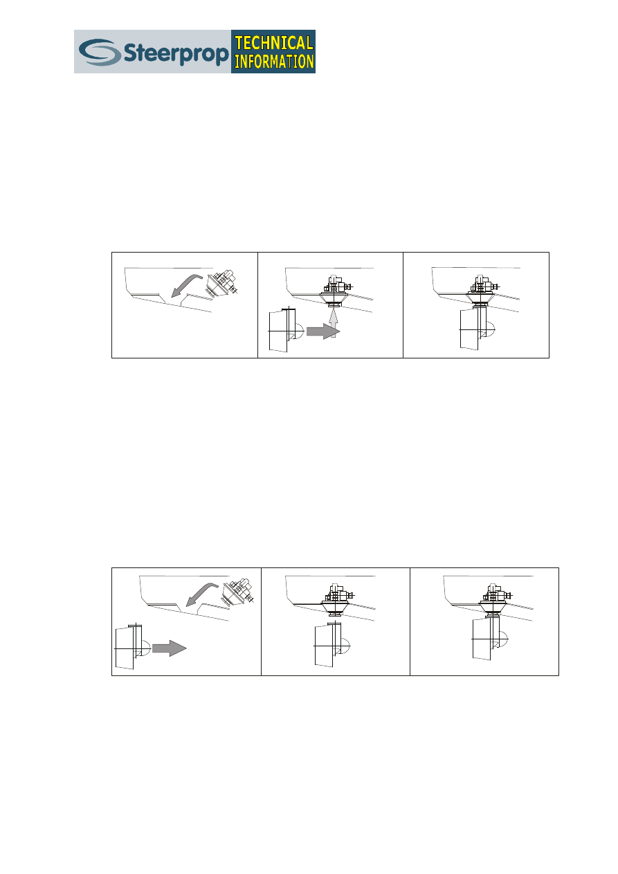
Small Bolt-in Mounting Cone
When the propulsor is installed using the small mounting cone there is no
need to compromise hull strength around the propulsors, as the needed
openings in the hull can be kept to a minimum. Mounting cone installation
allows the propulsor to be installed in one piece from below or in two
pieces, upper gearbox from above and lower gearbox from below.
Fig. 6.
Small bolt-in mounting cone installation – in one piece: 1) the propulsor is brought below
the hull; 2) the propulsor is turned in way of the trunk and lifted into position; 3) the
propulsor is bolted into the trunk and the clutch assembly is installed
2/2001
April 2001
DESIGNERS’ CHECKLIST Nº 2
Offshore Support Vessels
7
Fig. 7.
Small bolt-in mounting cone installation – in two parts: 1) the upper part is installed from
above, the lower part is brought into place from below the hull; 2) the upper part is bolted
into the hull; 3) the lower part is lifted into place and bolted to the upper part
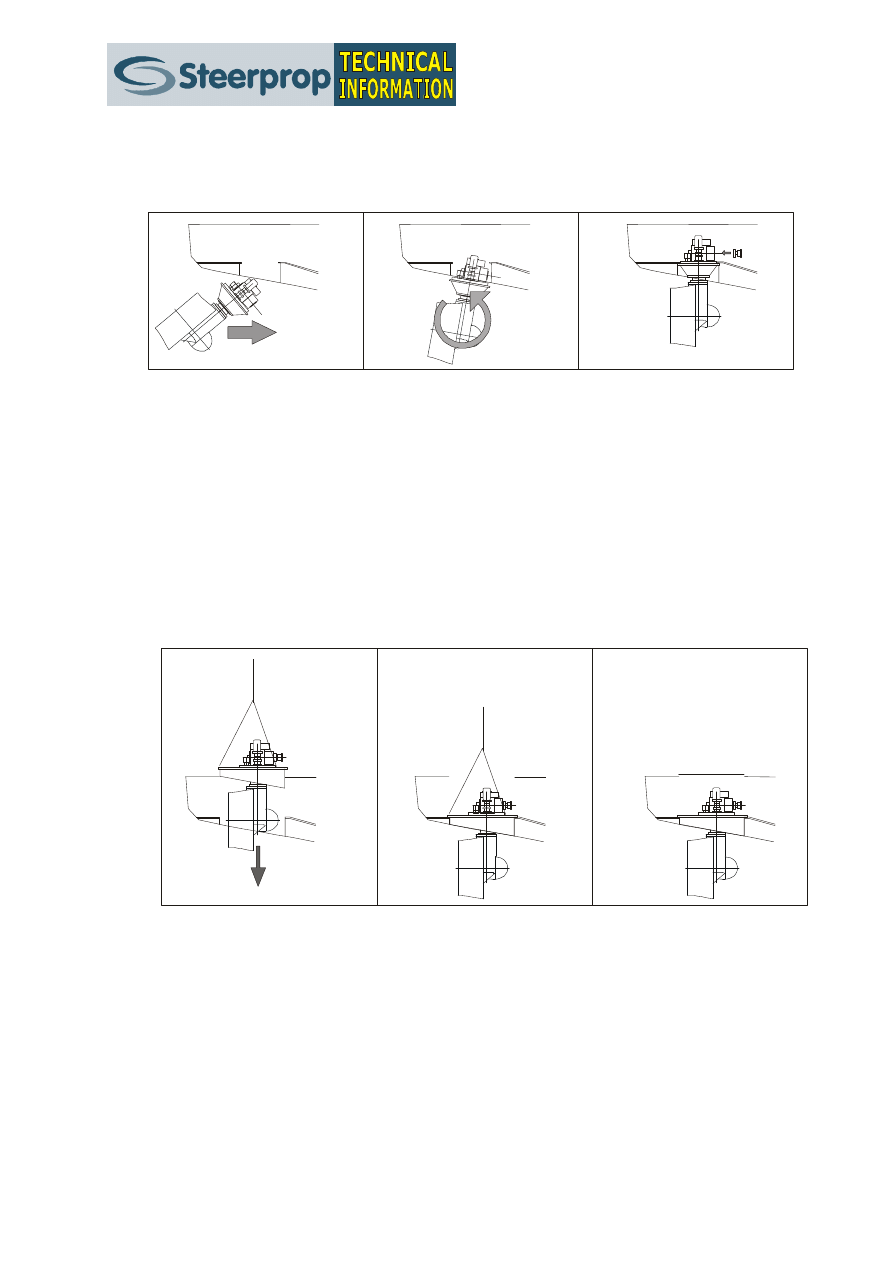
Large Mounting Adapter
The use of a large mounting adapter allows the complete propulsor to be
lifted onboard in one piece. Often it is possible to do so even with the
vessel in water. This feature also enables the propulsor to be lifted off the
vessel for repairs and maintenance without dry-docking the vessel. See
fig. 8.
Fig. 8.
Large bolt-in mounting adapter installation: 1) the propulsor is lifted onboard; 2) the
propulsor is bolted to the trunk flange; 3) the deck hatch is bolted or welded into place
above the propulsor
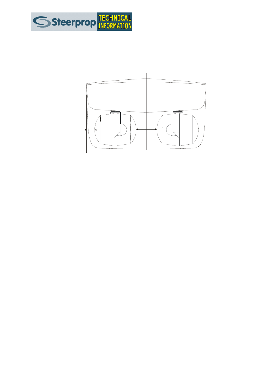
14.
Distance between the Propulsor Units
In order to improve the overall performance, especially the
manoeuvrability of the vessel, the unit should be installed as far from each
other as possible. Minimum recommended distance between the units is
the unit turning diameter + 500 mm.
2/2001
April 2001
DESIGNERS’ CHECKLIST Nº 2
Offshore Support Vessels
8
It is also recommended that the distance from the vessel side to the unit
centre is more than ½ unit turning diameter + 500 mm, in order to
prevent the units from touching jetties or other vessels when heeling.
min.
500 mm
min.
500 mm
Fig. 9.
Minimum distance between the units as well as between the side and the units are 500 mm
The beam of the vessel should, of course, be designed to allow the
required units to be installed accordingly.
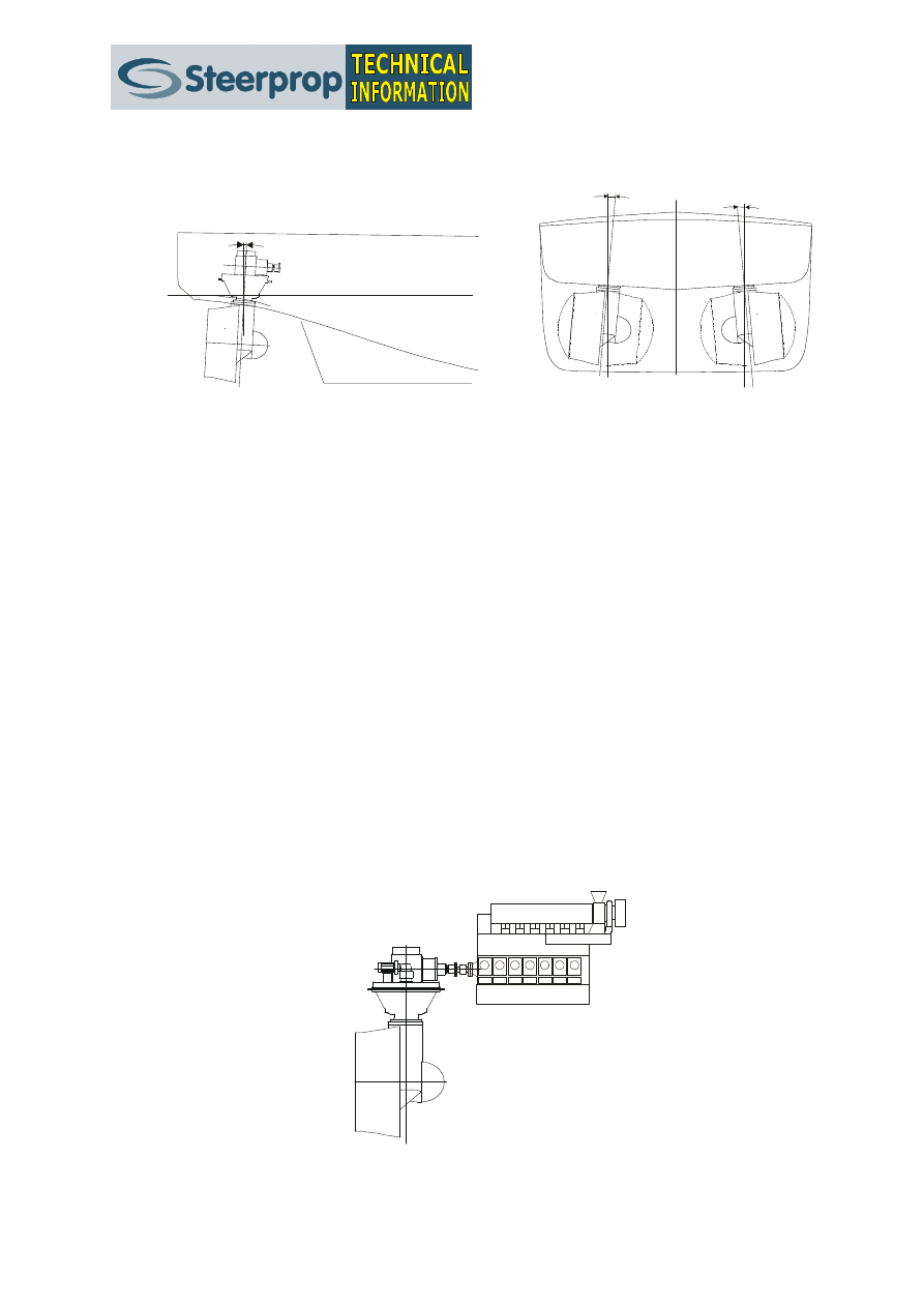
15.
Propulsor Tilting and Heeling
The propulsor units need not to be installed vertically, but can be both
tilted (longitudinally) and heeled (laterally) in order to achieve some
benefits. Typically the units are tilted, up to 3º …5º in order to decrease
the cardan shaft angles on the intermediate shaft. To achieve same
lifetime expectancy / maintenance interval for all the cardan bearings the
prime mover should be tilted correspondingly. Note that some main engine
manufacturers have strict maximum angles for engine tilt, thus also
restricting the propulsor tilt angle.
A tilt of 2º …3º is in any case recommended to improve the hydrodynamic
efficiency of the installation.
If the main engines need to be installed close to each other, the distance
between the propulsors can be maximized (and performance improved) by
a) using oblique intermediate shaft angles – note maximum cardan shaft
angles! – and/or b) by heeling the units outwards. Maximum heel angle is
to be determined case by case.
2/2001
April 2001
DESIGNERS’ CHECKLIST Nº 2
Offshore Support Vessels
9
tilt 3
o
heel 5
o
heel 5
o
Fig. 10. The units can be installed either tilted or heeled, or both. A tilt of 2º …3º is recommended to
optimise the water inflow to the propeller.
INTERMEDIATE SHAFTS
16.
Shaft Arrangements
The power train between the prime mover and the propulsor is by an
intermediate shaft. Depending on application and installation there are
several different possibilities for the intermediate shaft layout. In the
shortest case the shaft is only a tooth coupling and a flexible coupling
between the engine flywheel and the propulsor input flange.
In order to prevent the forces from the propulsor and the shafts to
damage the prime mover a flexible coupling has always to be installed
between the engine flywheel and the intermediate shaft package.
Tooth Coupling and Flexible Coupling
This is the shortest possible intermediate shaft installation, where the
shaft is a mere tooth coupling connected to the propulsor flange at one
end and to the flexible coupling on the prime mover flywheel.
Fig. 11. Using only a tooth coupling and a flexible coupling results in the shortest possible
intermediate shaft line arrangement
2/2001
April 2001
DESIGNERS’ CHECKLIST Nº 2
Offshore Support Vessels
10
Stub Shaft
The next shortest intermediate shaft is a short, so called stub shaft. The
shaft should be equipped with a pair of bearings to take the gravity load of
the shaft and thus the shortest possible length is one that provides for
space for the bearings. The stub shaft is usually fixed by flanges to the
propulsor input flange and the flexible coupling on the prime mover
flywheel.
Fig. 12. The stub shaft arrangement is another very compact installation method.
Centalink
If a short shaft without bearings is preferred a possibility is to use a so-
called flexible shaft, e.g. Centalink, where the shaft (normally of tube
type) is integrated to torsionally stiff flexible elements at each end of the
shaft.
Carbon Fibre Shaft
A novel solution for straight shaft installations is to use a large diameter
hollow carbon fibre shaft, which requires no bearings. The use of a carbon
fibre shaft is feasible in vessels, where a straight steel shaft otherwise
would be used. The carbon fibre shaft will save weight and installation
work compared to a conventional shaft with bearings and bearing
foundations. The carbon fibre shaft is using the same flexible elements as
in the Centalink solution above. Maximum length of a single piece shaft is
approx. 8 m.
2/2001
April 2001
DESIGNERS’ CHECKLIST Nº 2
Offshore Support Vessels
11
Fig. 13. The “flexible” shaft line arrangement – with no bearings – enables a fast and easy
installation of the intermediate shaft.
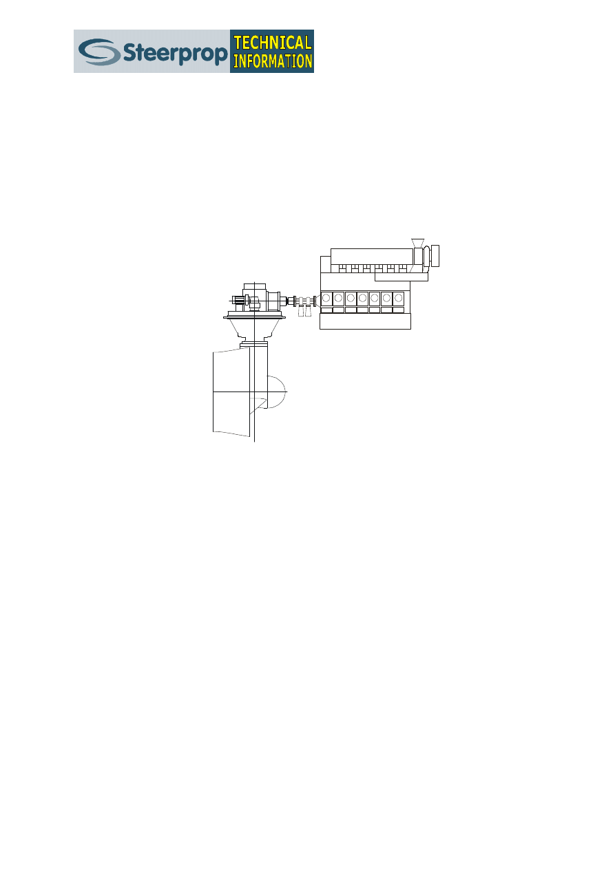
Single Cardan Shaft
If the engine is installed close to the same level as the propulsor and
rather close to each other a single cardan shaft can be used as the
intermediate shaft. In order not to damage the engine a stub shaft is
required, at least for power ratings above, say 600 kW. The stub shaft
requires a pair of bearings capable of taking axial forces and to take the
shaft weight. Note that the cardan shaft cannot be used with very small
angles; a minimum of 1º is normally required to ensure that the joint
bearings are moving.
Fig. 14. Sometimes it is feasible to use the single cardan shaft solution. Also this installation will
require a stub shaft and flexible coupling.

2/2001
April 2001
DESIGNERS’ CHECKLIST Nº 2
Offshore Support Vessels
12
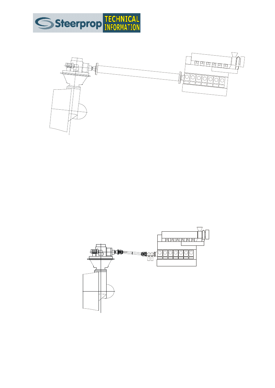
Typical Intermediate Shaft
The typical intermediate shaft arrangement on an offshore support vessel
with direct diesel drive comprises cardan shafts and a rather long straight
shaft. Also this arrangement will require a stub shaft at the prime mover
end as well as a flexible coupling to save the prime mover from damage.
Fig. 15. The typical intermediate shaft comprise two cardan shafts with a long straight shaft in
between. At the prime mover end a stub shaft and a flexible coupling will be required
17.
Shaft Angle
The height difference between prime mover flywheel and azimuth
propulsor input flange should be kept as small as possible. Maximum
allowed height is dependent on distance between the prime mover and
cardan shafts chosen.
Maximum usable angle is approximately 7.5º per joint, due to cardan shaft
rpm, bearing lifetime, and vibration. Use of the maximum angle has to be
separately checked. In order to avoid later problems, maximum
recommended angle is 6 ...6.5º per joint.
max. 15
o
Fig. 16 The angle of the intermediate shaft should be minimized - maximum recommended angle is
usually 15º
2/2001
April 2001
DESIGNERS’ CHECKLIST Nº 2
Offshore Support Vessels
13
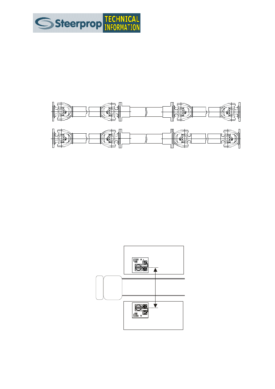
18.
Cardan Joint Phasing.
In order to improve the performance and lifetime of the cardans as well as
to reduce the risk for vibration problems on the intermediate shaft, the
cardan shaft joints at each end of the intermediate shaft should be in the
same phase for an odd number of shaft bearings and in different phase for
an even number of bearings.
Fig. 17 Cardan shaft phasing. Above with same phase for intermediate shaft with odd number of
bearings. Below with different phasing for intermediate shafts with even number of
bearings.
CONTROL LAYOUT
19.
Control Layout
The azimuth propulsor controls should be positioned in a way to enable the
helmsman to easily concentrate on the operations, not on how to handle
his vessel. The optimum solution is to place the control cabinets on each
side of the steering position. The distance between the cabinets should
allow a helmsman’s chair to fit between them, but the distance between
the propulsor controls should be kept between 55 cm and 65 cm.
55 ...65 cm
Fig. 18 A typical single steering position layout with a “walk-through” control layout. The distance
between the azimuth propulsor controls should be 55-65 cm.

2/2001
April 2001
DESIGNERS’ CHECKLIST Nº 2
Offshore Support Vessels
14
PROPULSOR ROOM SPACE
20.
Propulsor Room Space
There should be enough internal height in the propulsor room to allow for
installation as well as maintenance of the units. Recommended is a
minimum height of 200 …300 mm above the units. A separate bolted-on
maintenance hatch can be installed above the unit if enough height is
otherwise not available. The Steerprop Azimuth Propulsors are designed to
be as short as possible, i.e. the internal height requirement is minimised
and thus the units are suitable also for very low deck heights.
MAIN ENGINE
21.
Main Engine Choice
The propeller and main engine should be chosen together in order to
ensure that there is enough of torque available even in conditions with
negative water inflow to the propellers. If not, there is risk for engine
overload and stalling in a critical phase of ship handling.
EXTERNAL CONNECTIONS
22.
Electricity
The Steerprop propulsors require an external feed of electricity for the
control, for the display and emergency steering as well as for the alarms.
The system is of 24 V DC type and the electricity is required to the control
cabinets, normally situated in the engine room.
The electricity demand is approx. 300 W for the primary steering, approx
100 W for the emergency steering and display and approx. 50 W for the
alarms.
The electricity feed is required to be continuous with a battery backup.
23.
Cabling
The controls will require three cables for each propulsor to be drawn
between the wheelhouse control stand and the engine room / propulsor
room. There is one cable for the main control, one for the emergency
control and display and on cable for the alarms.

2/2001
April 2001
DESIGNERS’ CHECKLIST Nº 2
Offshore Support Vessels
15
24.
External Tanks
The Steerprop propulsors require a shaft seal tank of approx. 20 litre
capacity for each propulsor to be installed in the propulsor room. For units
with hydraulic steering a hydraulic unit - comprising required tanks
(capacity 60 …100 litres), filters, valves and coolers – need to be installed
close to each propulsor. The unit is delivered as a part of the Steerprop
delivery. The hydraulic unit need to be connected to the propulsor with 6
pipes between the propulsor and the hydraulic unit and 5 pipes between
the hydraulic unit and the propulsor.
25.
Cooling
The Steerprop units are equipped with coolers that need to be connected
to a cooling water system (fresh or sea water) the water capacity need is
100 …200 litres/min, depending on propulsor size and power. These values
are for an input water temperature of +32º C.

Steerprop Ltd.
P.O. Box 217
FIN-26101 RAUMA
Finland
e-mail: steerprop@steerprop.com
phone: +358 2 8387 7900
fax:
+358 2 8387 7910
w w w . s t e e r p r o p . c o m
Wyszukiwarka
Podobne podstrony:
Palladium Checklist
Cessna 172XP Small Checklist
checklist forestry horticulture
checklist radio tv theatre events
checklist undertaker
SSAS TEST Checklist, Akademia Morska (Szczecin), Semestr V, Inspekcje Morskie
checkliste
checklist asphalt work
domain controller checklist OMO5UL6LZCXY75RCL5UP32W2O5HKIIJOVHWHHYY
PBO TD02 C01 Shipmaster Monthly Checklist
Checklist 7
A Surgical Safety Checklist to Reduce Morbidity and Mortality in a Global Population
Pilot Embarkation Checklist
Checklist 1
infrastructure server checklist Y67PKVZL2TBVBV3Z3IYCFN45BUIMBB2GKO4GCXY
STET SSP Checklist Ver2
CHECKLISTA
checklist sport centres
checklist1[1]
więcej podobnych podstron