4C
Torque wrench settings
Nm
lbf ft
AIR non-return valve to pipe . . . . . . . . . . . . . . . . . . . . . . . . . . . . . . . . . .
30
22
AIR pipe support bracket to manifold . . . . . . . . . . . . . . . . . . . . . . . . . .
8
6
AIR pipe to manifold . . . . . . . . . . . . . . . . . . . . . . . . . . . . . . . . . . . . . . . .
20
15
AIR pipe to support bracket . . . . . . . . . . . . . . . . . . . . . . . . . . . . . . . . . .
8
6
AIR pump bracket to protective shield . . . . . . . . . . . . . . . . . . . . . . . . . .
10
7
AIR pump to wheel arch . . . . . . . . . . . . . . . . . . . . . . . . . . . . . . . . . . . . .
20
15
AIR pump to insulator . . . . . . . . . . . . . . . . . . . . . . . . . . . . . . . . . . . . . . .
10
7
AIR valves to bracket . . . . . . . . . . . . . . . . . . . . . . . . . . . . . . . . . . . . . . .
4
3
Carbon canister . . . . . . . . . . . . . . . . . . . . . . . . . . . . . . . . . . . . . . . . . . .
4
3
EGR valve . . . . . . . . . . . . . . . . . . . . . . . . . . . . . . . . . . . . . . . . . . . . . . . .
20
15
Heat shield . . . . . . . . . . . . . . . . . . . . . . . . . . . . . . . . . . . . . . . . . . . . . . .
8
6
Oxygen sensor . . . . . . . . . . . . . . . . . . . . . . . . . . . . . . . . . . . . . . . . . . . .
30
22
Chapter 4 Part C:
Fuel and exhaust systems - exhaust and emissions
AIR cut-off valve - removal, testing and refitting . . . . . . . . . . . . . . . . .7
AIR pipe and non-return valve - removal and refitting . . . . . . . . . . . . .9
AIR pump assembly (Simtec system) - removal and refitting . . . . . . . .6
AIR switchover valve - removal and refitting . . . . . . . . . . . . . . . . . . . .8
Carbon canister - removal and refitting . . . . . . . . . . . . . . . . . . . . . . .11
Catalytic converter - description, general and precautions . . . . . . . .10
EGR module (X 16 SZ models) - removal and refitting . . . . . . . . . . . . .5
EGR valve (Multec system models) - testing, removal and refitting . . .3
EGR valve (Simtec system) - testing, removal and refitting . . . . . . . . .4
Emissions control systems - general . . . . . . . . . . . . . . . . . . . . . . . . . .1
Exhaust gas recirculation (EGR) system - general . . . . . . . . . . . . . . . .2
Exhaust manifold - removal and refitting . . . . . . . . . . . . . . . . . . . . . .13
Exhaust system - checking, removal and refitting . . . . . . . . . . . . . . .14
Oxygen sensor (catalytic converter models) - removal and refitting .12
4C•1
Specifications
Contents
1
Emissions control systems -
general
General
Multec system
1 An evaporative emissions control system is
fitted to minimise the escape into the
atmosphere of unburned hydrocarbons.
2 The fuel tank filler cap is sealed and a
charcoal canister is mounted under the
right-hand front wing to collect the petrol
vapours generated in the tank when the
vehicle is parked. It stores them until they can
be purged from the canister into the inlet tract
to be burned by the engine during normal
combustion. The canister’s control valve (on
the top of the canister) is opened by a vacuum
pipe from the front of the throttle body on C16
NZ, C16 NZ2 and C18 NZ engines. On X16 SZ
it’s opened by an electronically activated
purge valve, mounted on the camshaft
housing.
Motronic system
3 The system is as described in Chapter 4B,
except that the charcoal canister is purged
under the control of the fuel injection/ignition
system module through the fuel tank vent
valve. To ensure that the engine runs correctly
when it is cold and/or idling, and to protect
the catalytic converter from the effects of an
over-rich mixture, the valve is not opened by
the module until the engine is under partial or
full load. The valve solenoid is then modulated
on and off to allow the stored vapour to pass
into the inlet tract.
4 Canister removal and refitting is as
described in Section 11.
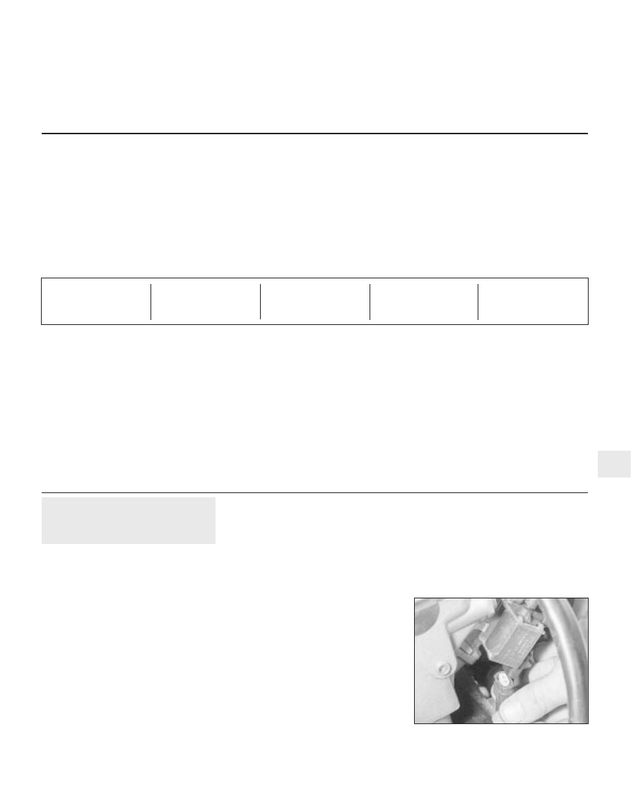
5 On C20 NE engines, the vent valve is
mounted above the injectors for cylinders 2
and 4. To remove it, disconnect the battery
negative lead and the valve wiring plug, then
disconnect the two vent hoses having made
note of their connections. Either remove the
valve from its mounting bracket, or unbolt the
bracket, as required.
6 On C20 XE engines, the vent valve is
mounted on the left-hand end of the engine,
underneath the end of the fuel injector wiring
harness housing (see illustration). Removal
and refitting is as described in the previous
paragraph.
Simtec system
7 For information refer to “General
description”, in Chapter 4B. Note that “AIR”,
is an abbreviation for the secondary Air
Injection Reactor system used on this model.
Easy, suitable for
novice with little
experience
Fairly easy, suitable
for beginner with
some experience
Fairly difficult,
suitable for competent
DIY mechanic
Difficult, suitable for
experienced DIY
mechanic
Very difficult,
suitable for expert DIY
or professional
Degrees of difficulty
5
4
3
2
1
1.6 Disconnecting the fuel tank vent valve
wiring
2
Exhaust gas recirculation
(EGR) system - general
The system reintroduces small amounts of
exhaust gas into the combustion cycle to
reduce the generation of oxides of nitrogen
(NOx).
On C16 NZ, C16 NZ2 and C18 NZ engines,
the volume of exhaust gas reintroduced is
governed by manifold vacuum, through the
EGR valve mounted on the inlet manifold.
When the valve is opened small amounts of
exhaust gas are allowed to enter the inlet
tract, passing through ports in the cylinder
head.
On X16 SZ engines the EGR valve is
operated by an EGR module, mounted on the
left-hand side of the engine compartment
behind the battery. This module amplifies
signals received from the fuel system ECU
and operates the EGR valve electronically
providing precise control of exhaust gas
recirculation under all engine conditions.
3
EGR valve (Multec system
models) - testing, removal and
refitting
2
Testing
1 On C16 NZ, C16 NZ2 and C18 NZ engines,
it is recommended that the system is checked
annually, by checking the movement of the
valve’s diaphragm carrier plate as follows.
Note that the carrier plate is visible only
through the apertures in the underside of the
valve, so a battery-operated torch and small
mirror may be useful. On X16 SZ engines,
Vauxhall test equipment is necessary to check
the EGR system.
2 With the engine fully warmed up to normal
operating temperature and idling, briefly open
and close the throttle. The carrier plate should
move upwards as the manifold vacuum
changes. When the engine is idling smoothly
again, press the carrier plate upwards (do this
very carefully, so that the plate is not distorted or
the diaphragm damaged). The idle speed should
drop significantly (approximately 100 rpm).
3 If the valve does not respond as described,
it must be cleaned.
Removal
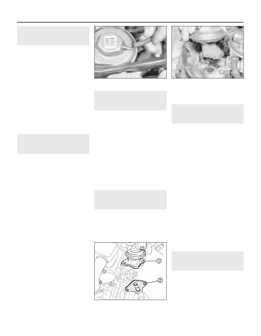
4 Pull off the hose from the valve, then unbolt
the valve and remove it (see illustrations).
Clean away all carbon using a wire brush and
a pointed tool, but take care not to damage
the valve seat. Renew the valve gasket to
prevent induction leaks.
Refitting
5 Refit the valve and reconnect the hose,
then recheck the system’s performance; if
there is no improvement, the valve must be
renewed.
4
EGR valve (Simtec system) -
testing, removal and refitting
3
Note: A new gasket will be required when
refitting the valve.
Removal
1 Disconnect the battery negative lead.
2 Remove wiring harness and vacuum hose.
3 Mark position of the valve, to ensure
correct relocation.
4 Undo the 3 bolts, and remove the valve
from the dual spark ignition coil’s coolant
flange.
Refitting
5 Clean the sealing surfaces of the valve and
flange.
6 Refit the valve with a new gasket and line
up the marks made before removal (see
illustration).
5
EGR module (X16 SZ
models) - removal and
refitting
2
Removal
1 Disconnect the knock module from its
bracket (refer to Chapter 4B, if necessary),
and place to one side.
2 Remove wiring plug from module. Remove
module from bracket.
Refitting
3 Refitting is a reversal of removal.
6
AIR pump assembly (Simtec
system) - removal and refitting
3
Removal
1 Chock the rear wheels, jack up the front of
the vehicle and support it on axle stands
placed under the body side members (see
“Jacking and Vehicle Support”)
2 Remove the left hand front wheel and inner
wheel arch lining.
3 Loosen the hose clamp and remove the air
duct hose from the pump.
4 Disconnect the battery negative lead.
5 Undo the securing nuts and remove the
pump assembly from its location. Disconnect
the wiring plug.
6 Remove the wiring plug from the pump’s
bracket.
7 Mark the position of the pump on it’s
bracket before separating.
8 Remove the fixing bolts and disconnect the
pump from it’s insulator.
9 The insulator can also be checked by
removing the 3 nuts, securing the protective
shield. Before removing, mark the shield and
insulator. Replace if necessary.
10 Check the pump’s air cleaner for damage.
Refitting
11 Refitting is a reversal of removal. Ensure
correct alignment of the components.
7
AIR cut-off valve - removal,
testing and refitting
3
Removal
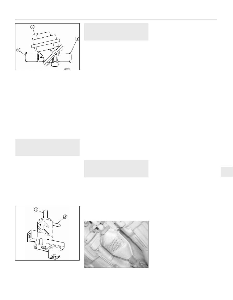
1 Before removal, mark on the cut-off valve,
the direction of flow towards the non-return
valve (see illustration).
2 Disconnect and remove the air duct and
vacuum hoses.
3 Undo the switchover valve’s bolts and
move to one side.
4C•2 Fuel and exhaust systems - exhaust and emissions
3.4 Disconnecting the vacuum hose from
the exhaust gas recirculation valve
4.6 EGR valve
1 Valve 2 Gasket
3.4B Withdrawing the exhaust gas
recirculation valve
4 The cut-off valve can now be removed from
the bracket.
Testing
5 To test the cut-off valve a vacuum hand
pump with gauge will be required. If available,
connect to the cut-off valve and ensure that
air through-flow aperture is fully open.
Refitting
6 Refitting is a reversal of removal. Ensure
valve is fitted in the correct direction.
8
AIR switchover valve -
removal and refitting
3
Removal
1 Disconnect the battery negative lead.
2 Disconnect wiring plug from the valve.
3 Mark the location of the vacuum hoses
before removing them from the valve.
4 After disconnecting the hoses undo the two
bolts, and remove them from its bracket.
Refitting
5 Refitting is a reversal of removal. Ensure
hoses are fitted correctly (see illustration).
9
AIR pipe and non-return
valve - removal and refitting
3
Note: New air pipe washers will be required
when refitting.
Removal
1 Remove the non-return valve air duct hose.
2 Undo the bolts engine lifting eye bracket,
and turn the bracket on to its left hand side.
3 Remove the pipe support bracket by
releasing its three bolts.
4 Remove the heat shield that is secured by
two bolts.
5 The air pipe can now be removed by
releasing the two securing bolts.
6 If necessary the non-return valve can now
be disconnected.
7 Carefully clamp the pipe using a vice with
protective jaws. Unbolt the valve from the
pipe, clean and inspect for damage.
Refitting
8 Before refitting, coat the threads of the non-
return valve with sealing compound (i.e.
Vauxhall part no. 90094714).
9 Use new washers when refitting the pipe,
(take care as the washers have sharp edges).
Coat the pipe mounting bolts with assembly
paste (i.e. Vauxhall part no. 90513210), before
refitting.
10 Refitting is a reversal of removal.
Retighten to correct torque as shown in Spec-
ifications.
10 Catalytic converter -
description, general and
precautions
Note: The catalytic converter is not a filter. It
creates a chemical reaction, but it is not
affected by that reaction.
Description
1 Certain models are available with a catalytic
converter, to reduce exhaust emissions.
These models can be identified by a ‘C’ or ‘X’,
prefixing the engine code.
2 The purpose of the catalytic converter is to
change potentially harmful hydrocarbon and
carbon monoxide exhaust gases into harmless
gases and water vapour. The converter
consists of a stainless steel canister containing
a catalyst-coated honeycomb ceramic. The
catalyst is a mixture of three precious metals,
platinum, palladium and rhodium.
3 The exhaust gases pass freely through the
honeycomb, where the catalyst speeds up the
chemical change of the exhaust gases,
without being permanently altered itself.
4 To avoid damage to the catalyst, the engine
must be kept properly tuned, and unleaded
petrol must always be used. Normal leaded
petrol will “poison” the catalyst, and must not
be used.
5 To enable the Motronic engine management
system to achieve complete combustion of the
fuel mixture, and thus to minimise exhaust
emissions, an oxygen sensor is fitted in the
exhaust gas stream. The sensor monitors the
oxygen level in the exhaust gas, and sends a
signal to the Motronic module. The module
constantly alters the fuel/air mixture within a
narrow band to reduce emissions, and to allow
the catalytic converter to operate at maximum
efficiency. No adjustment of idle mixture is
therefore possible on models fitted with a
catalytic converter.
General
6 Ninety-nine per cent of exhaust gases, from
a petrol engine (however efficient or well
tuned), consists of nitrogen (N
2
), carbon
dioxide (CO
2
), oxygen (O
2
), other inert gases
and water vapour (H
2
O). The remaining 1% is
made up of the noxious materials that are
currently seen (except CO
2
), as the major
polluters of the environment. Carbon
monoxide (CO), unburned hydrocarbons (HC),
oxides of nitrogen (NOx) and some solid
matter, including a small lead content.
7 The device most commonly used to clean
up vehicle exhausts is the catalytic converter.
It is fitted into the vehicle’s exhaust system
and uses precious metals (platinum and
palladium or rhodium) as catalysts to speed
up the reaction between the pollutants and
the oxygen in the exhaust gases. CO and HC
being oxidised to form H
2
O and CO
2
and (in
the three-way type of catalytic converter) NOx
being reduced to N
2
.
8 The converter consists of an element of
ceramic honeycomb, coated with a
combination of precious metals in such a way
as to produce a vast surface area over which
the exhaust gases must flow. The three-way
closed-loop type converter fitted to these
models can remove over 90% of pollutants.
9 The catalytic converter is a reliable and
simple device that needs no maintenance.
However there are some facts that an owner
should be aware if the converter is to function
properly for its full service life (see
illustration).
a) DO NOT use leaded petrol in a vehicle
equipped with a catalytic converter. The
lead will coat the precious metals,
reducing their converting efficiency and
will eventually destroy the converter.
Fuel and exhaust systems - exhaust and emissions 4C•3
10.9 The catalytic converter is protected
by heat shields
8.5 AIR switchover valve
1 Connection to brake servo vacuum hose
2 Connection to cut-off valve
7.1 AIR cut-off valve
1 Connection to AIR pump
2 Connection to AIR switchover valve
3 Connection to AIR non-return valve
4C
b) Always keep the ignition and fuel systems
well maintained according to the
manufacturers schedule (see “Routine
maintenance” and the relevant Chapter).
In particular, ensure that the air cleaner
filter element, the fuel filter and the spark
plugs are renewed at the correct intervals.
If the inlet air/fuel mixture is allowed to
become too rich due to neglect, the
unburned surplus will enter and burn in
the catalytic converter, overheating the
element and eventually destroying the
converter.
c) If the engine develops a misfire, do not
drive the vehicle at all (or at least as little
as possible) until the fault is cured. The
misfire will allow unburned fuel to enter
the converter, which will result in its
overheating, as noted above.
d) The engine control indicator (the outline
of an engine with a lightning symbol
superimposed), will light when the ignition
is switched on and the engine is started,
then it will go out. While it may light briefly
while the engine is running, it should go
out again immediately and stays unlit. If it
lights and stays on while the engine is
running, seek the advice of a Vauxhall
dealer as soon as possible. A fault has
occurred in the fuel injection/ignition
system that, apart from increasing fuel
consumption and impairing the engine’s
performance, may damage the catalytic
converter.
e) DO NOT push or tow-start the vehicle.
This will soak the catalytic converter in
unburned fuel causing it to overheat when
the engine does start see (b) above.
f) DO NOT switch off the ignition at high
engine speeds. If the ignition is switched
off at anything above idle speed,
unburned fuel will enter the (very hot)
catalytic converter, with the possible risk
of its igniting on the element and
damaging the converter.
g) DO NOT use fuel or engine oil additives.
These may contain substances harmful to
the catalytic converter.
h) DO NOT continue to use the vehicle if the
engine burns oil to the extent of leaving a
visible trail of blue smoke. The unburned
carbon deposits will clog the converter
passages and reduce its efficiency; in
severe cases the element will overheat.
i) Remember that the catalytic converter
operates at very high temperatures hence
the heat shields on the vehicle’s under-
body and the casing will become hot
enough to ignite combustible materials
that brush against it. DO NOT, therefore,
park the vehicle in dry undergrowth, over
long grass or over piles of dead leaves.
j) Remember that the catalytic converter is
FRAGlLE. Do not strike it with tools during
servicing work. Take great care when
working on the exhaust system. Ensure
that the converter is well clear of any
jacks or other lifting gear used to raise the
vehicle. Do not drive the vehicle over
rough ground, road humps, etc., in such a
way as to ground the exhaust system.
k) In some cases, particularly when the
vehicle is new and/or is used for
stop/start driving, a sulphurous smell (like
that of rotten eggs) may be noticed from
the exhaust. This is common to many
catalytic converter-equipped vehicles and
seems to be due to the small amount of
sulphur found in some petrol’s reacting
with hydrogen in the exhaust to produce
hydrogen sulphide (CS) gas. While this
gas is toxic, it is not produced in sufficient
amounts to be a problem. Once the
vehicle has covered a few thousand miles
the problem should disappear. In the
meanwhile a change of driving style or of
the brand of petrol may effect a solution.
l) The catalytic converter, used on a
well-maintained and well-driven vehicle,
should last for between 50 000 and 100
000 miles. From this point on, careful
checks should be made at all specified
service intervals of the CO level to ensure
that the converter is still operating
efficiently. If the converter is no longer
effective it must be renewed.
11 Carbon canister - removal
and refitting
3
Removal
1 Apply the handbrake, then jack up the front
of the vehicle, and support securely on axle
stands placed under the body side members
(see “Jacking and Vehicle Support”).
2 Remove the front right hand wheel and
wheel arch liner.
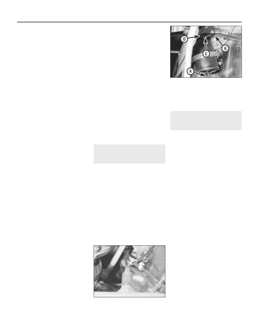
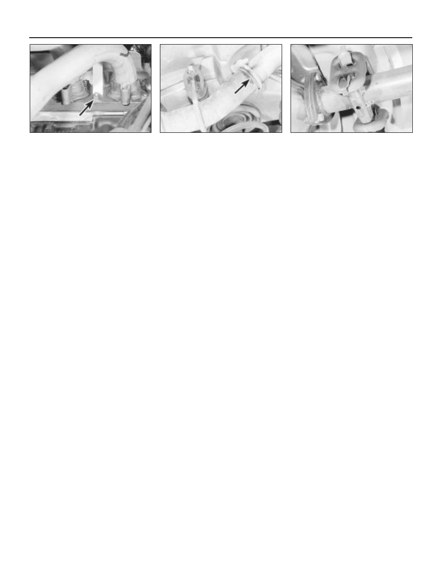
3 Note the hose and pipe connections to the
canister, or label them, to ensure that they are
reconnected to their original unions, then
disconnect them (see illustration). Unscrew
the two nuts securing the canister mounting
bracket to the vehicle body.
Refitting
4 Refitting is a reversal of removal, however
ensure correct fitment of hose and pipes.
12 Oxygen sensor (catalytic
converter models) - removal
and refitting
3
Note: This sensor is also known as a Lambda
sensor.
Removal
1 Disconnect the battery negative lead.
2 Disconnect the oxygen sensor wiring plug,
which is located behind the coolant expansion
tank.
3 Apply the handbrake, then jack up the front
of the vehicle, and support securely on axle
stands placed under the body side members.
4 On DOHC models, remove the engine
undershield, as described in Chapter 11.
5 On models fitted with Multec injection
system, the sensor is screwed into the
exhaust manifold. Trace the wiring from the
sensor itself to the connector (either clipped
to the radiator cooling fan shroud or behind
the coolant expansion tank). Release it from
any clips or ties; disconnect the wiring before
unscrewing the sensor.
6 On other models, unscrew the oxygen
sensor from the front section of the exhaust
system (see illustration). It is advisable to
wear gloves, as the exhaust system will be
extremely hot.
7 Withdraw the oxygen sensor and its wiring,
taking care not to burn the wiring on the
exhaust system. If the sensor is to be re-used,
take care that the sealing ring is not lost, and
that the sensor is not dropped.
Refitting
8 If a new sensor is being fitted, it will be
supplied with the threads coated in a special
grease to prevent it seizing in the exhaust
system.
9 If the original sensor is being refitted,
ensure that the screw thread is clean. Coat
the thread with a lithium based copper grease
(i.e. Vauxhall Part No. 90295397).
10 Refitting is a reversal of removal. Check
the exhaust system for leakage when the
engine is re-started.
4C•4 Fuel and exhaust systems - exhaust and emissions
12.6 Oxygen sensor location in front
section of exhaust system - DOHC models
11.3 Charcoal canister
A Vent to atmosphere
B Vapour feed hose from filler pipe
C Vapour exhaust hose to inlet tract
D Control valve vacuum pipe from
throttle body
13 Exhaust manifold - removal
and refitting
3
Note: New manifold-to-cylinder head, and
manifold-to-downpipe, gaskets must be used
on refitting. Exhaust manifolds on DOHC
models are of tubular design, which form part
of the front section of the exhaust.
Removal
1 Disconnect the battery negative lead.
2 Disconnect the HT leads from the spark
plugs, if necessary labelling them to ensure
refitting to the correct cylinders.
3 Loosen the clamp screw and disconnect
the air cleaner hot air tube from the shroud on
the manifold, if fitted. Remove the securing
screws and withdraw the hot air shroud from
the manifold.
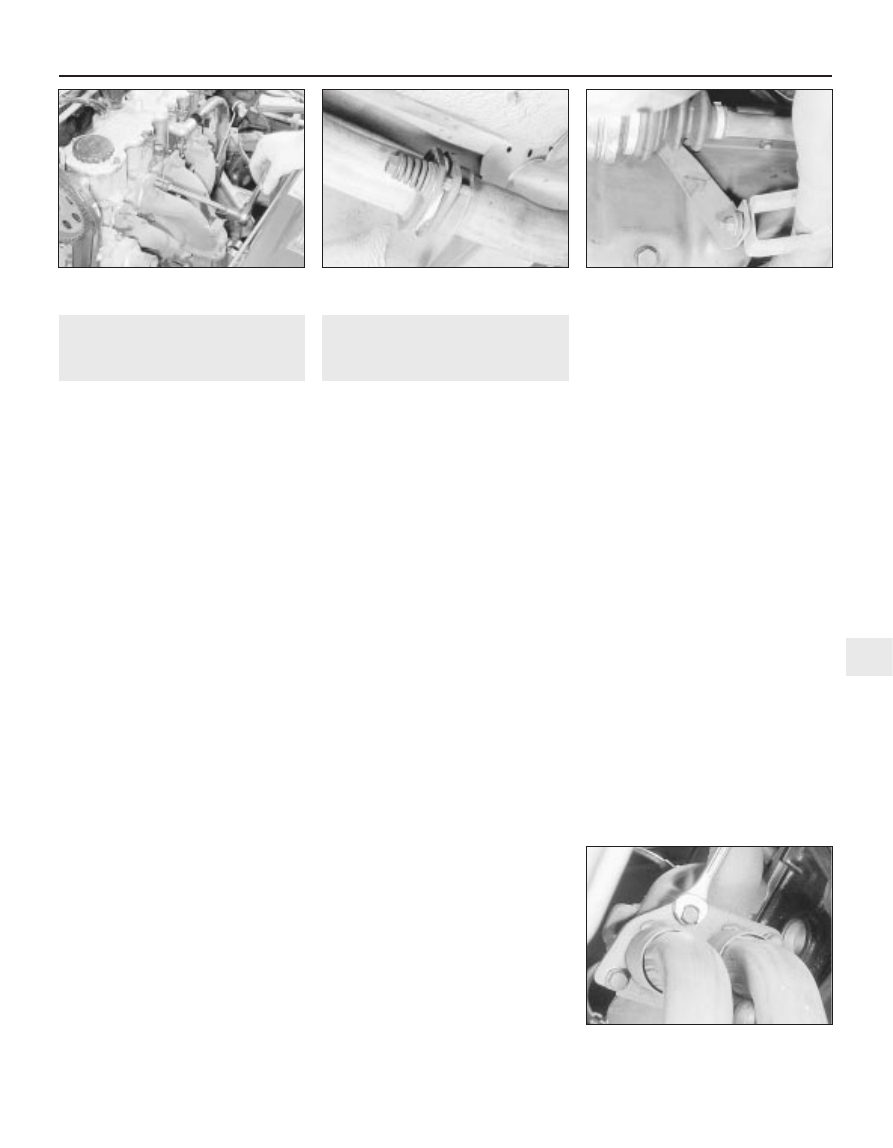
4 Working under the manifold, unscrew and
remove the four bolts securing the exhaust
downpipe to the manifold.
5 If fitted, disconnect the oxygen sensor
wiring
6 Separate the downpipe from the manifold,
and support with wire or string. Do not allow
the front section of the exhaust system to hang
under its own weight. Recover the gasket.
7 Unscrew the securing nuts, and withdraw
the manifold from the cylinder head (see
illustration). Recover the gasket.
8 It is possible that some of the manifold
studs may be unscrewed from the cylinder
head when the manifold securing nuts are
unscrewed. In this event, the studs should be
screwed back into the cylinder head once the
manifold has been removed, using two
manifold nuts locked together.
Refitting
9 Refit the manifold using a new gasket, and
tighten the securing nuts to the specified
torque.
10 Reconnect the exhaust downpipe to the
manifold, using a new gasket and tighten the
securing bolts to the specified torque.
11 Further refitting is a reversal of removal.
14 Exhaust system - checking,
removal and refitting
2
Note: All relevant gaskets and/or sealing rings
should be renewed on refitting
Checking
1 Periodically, the exhaust system should be
checked for signs of leaks or damage. Also
inspect the exhaust system rubber
mountings, and renew if necessary.
2 Small holes or cracks can be repaired using
proprietary exhaust repair products, but
where more serious corrosion or damage is
evident, renewal will be necessary.
Removal
3 The original factory-fitted exhaust system
consists of four separate sections, all of which
can be renewed individually.
4 On models fitted with a catalytic converter,
an oxygen sensor is fitted to the front section
of the exhaust. The catalytic converter is fitted
in place of the front expansion box in the
conventional exhaust system. The
manufacturers do not specify any renewal
intervals for the catalytic converter.
5 Before renewing an individual section of the
exhaust system, it is wise to inspect the
remaining sections. If corrosion or damage is
evident on more than one section of the
system, it may prove more economical to
renew the entire system.
6 Individual sections of the exhaust system
can be removed as follows.
Front section - SOHC models
7 On models with a catalytic converter,
disconnect the battery negative lead, and
disconnect the oxygen sensor wiring plug,
which is located behind the coolant expansion
tank.
8 Raise the vehicle, and support securely on
axle stands placed under the body side
members (see “Jacking and Vehicle
Support”).
9 Unscrew the two securing bolts, and
disconnect the exhaust front section from the
front expansion box or catalytic converter (as
applicable) at the flexible joint. Recover the
sealing ring and the springs (see illustration).
10 Unbolt the exhaust front section from the
bracket on the cylinder block (see
illustration).
11 Unscrew and remove the four bolts
securing the downpipe to the exhaust
manifold, and withdraw the exhaust front
section (see illustration). Recover the
downpipe-to-manifold gasket.
Refitting
12 Refitting is a reversal of removal, but use a
new gasket when reconnecting the downpipe
to the manifold, and a new sealing ring when
connecting the flexible joint. Tighten all fixings
to the specified torque.
Front section - DOHC models
Removal
13 Proceed as described in paragraphs 7
and 8.
14 Remove the engine undershield, as
described in Chapter 11.
15 Proceed as described in paragraphs 9
and 10.
16 Working in the engine compartment,
remove the bolts securing the exhaust
manifold heat shield to the cylinder head.
17 Unscrew the two lower exhaust manifold
securing nuts that also secure the heat shield
brackets, and withdraw the heat shield (see
illustration).
18 Unscrew the remaining manifold securing
nuts, then withdraw the manifold/exhaust
front section from the vehicle. Recover the
manifold gasket.
Fuel and exhaust systems - exhaust and emissions 4C•5
14.10 Exhaust front section support
bracket - SOHC models
14.11 Unscrewing a downpipe-to-exhaust
manifold bolt - SOHC models
14.9 Exhaust front section flexible joint -
SOHC models
13.7 Unscrewing an exhaust manifold
securing nut - SOHC models
4C
19 It is possible that some of the manifold
studs may be unscrewed from the cylinder
head when the manifold securing nuts are
unscrewed. In this event, the studs should be
screwed back into the cylinder head once the
manifold has been removed, using two
manifold nuts locked together.
Refitting
20 Refitting is a reversal of removal, but use a
new manifold gasket, and use a new sealing
ring when reconnecting the flexible joint.
Tighten all fixings to the specified torque.
Front expansion box/catalytic
converter
Removal
21 Proceed as described in paragraphs 8
and 9.
22 Unscrew the three securing nuts and
bolts, and disconnect the expansion
box/catalytic converter from the exhaust
centre section flanged joint. Recover the
gasket.
23 Withdraw the expansion box/catalytic
converter from the vehicle.
Refitting
24 Refitting is a reversal of removal, but use a
new sealing ring when reconnecting the
flexible joint, and a new gasket when
reconnecting the flanged joint. Tighten all
fixings to the specified torque.
Centre section
Removal
25 Raise the vehicle, and support securely on
axle stands placed under the body side
members.
26 Unscrew the clamp bolt, and disconnect
the exhaust centre section from the rear
section (see illustration). If necessary, tap
around the joint with a hammer to break the
seal, and gently prise the two sections apart.
Note that the end of the centre section fits
inside the rear section, to form a sleeve joint.
27 Proceed as described in paragraph 22.
28 Release the exhaust centre section from
its rubber mountings on the underbody, and
withdraw it from the vehicle (see illustration).
Refitting
29 Refitting is a reversal of removal, but use a
new gasket when reconnecting the flanged
joint, and lubricate the pipes with exhaust
assembly paste when connecting the centre
section to the rear section. Tighten all fixings
to the specified torque.
Rear section
Removal
30 Proceed as described in paragraphs 25
and 26.
31 Release the exhaust rear section from its
rubber mountings on the underbody, and
withdraw it from the vehicle.
Refitting
32 Refitting is a reversal of removal, but
lubricate the pipes with exhaust assembly
paste when connecting the rear section to the
centre section. Tighten the clamp bolt to the
specified torque.
4C•6 Fuel and exhaust systems - exhaust and emissions
14.28 Exhaust centre section forward
rubber mountings - DOHC models
14.26 Exhaust centre section-to-rear
section clamp (arrowed) - SOHC model
14.17 Exhaust manifold nut (arrowed)
securing exhaust heat shield - DOHC
models
Wyszukiwarka
Podobne podstrony:
1570
04c RACHUNEK ZYSKÓW I STRAT
30 A 1570 r 1600 r renesans, manieryzm
1570 Pius V Quo primum tempore
FIG 04C
zx 04c
FIG-04C
04c krzyw niez
1998 07 17 1570
IT CCTV 04C
1570
1570
04C Wyścig szczurów 09-10-2010, KSW Kędzierzyn spotkania, Spotkania i sprawozadnia K-K KSW
1570 05
29 A 1530 r 1570 r renesans, manieryzm
więcej podobnych podstron