
5
System type
. . . . . . . . . . . . . . . . . . . . . . . . . . . . . . . . . . . . . . . . . . .
12 volt, negative earth
Battery capacity
. . . . . . . . . . . . . . . . . . . . . . . . . . . . . . . . . . . . . . .
36, 44, 55 or 66 Ah
Alternator
Type . . . . . . . . . . . . . . . . . . . . . . . . . . . . . . . . . . . . . . . . . . . . . . . . . . . .
Bosch or Delco-Remy
Output . . . . . . . . . . . . . . . . . . . . . . . . . . . . . . . . . . . . . . . . . . . . . . . . . . .
55 or 70 A, depending upon model
Minimum brush length:
Bosch type alternator . . . . . . . . . . . . . . . . . . . . . . . . . . . . . . . . . . . . .
5.0 mm protrusion
Delco-Remy type alternator . . . . . . . . . . . . . . . . . . . . . . . . . . . . . . . .
11.0 mm overall length
Starter motor
Type . . . . . . . . . . . . . . . . . . . . . . . . . . . . . . . . . . . . . . . . . . . . . . . . . . . .
Pre-engaged, Bosch or Delco-Remy
Minimum brush length:
Bosch DF type starter motor . . . . . . . . . . . . . . . . . . . . . . . . . . . . . . .
11.5 mm
Bosch DM type starter motor . . . . . . . . . . . . . . . . . . . . . . . . . . . . . . .
3.0 mm
Bosch DW type starter motor . . . . . . . . . . . . . . . . . . . . . . . . . . . . . . .
4.5 mm
Delco-Remy type starter motor . . . . . . . . . . . . . . . . . . . . . . . . . . . . .
4.0 mm
System type
14 NV . . . . . . . . . . . . . . . . . . . . . . . . . . . . . . . . . . . . . . . . . . . . . . . . .
HEI (High Energy Ignition) system
16 SV and 18 SV . . . . . . . . . . . . . . . . . . . . . . . . . . . . . . . . . . . . . . . . .
MSTS-i (Microprocessor Spark Timing System)
C16 NZ, C16 NZ2 and C18 NZ . . . . . . . . . . . . . . . . . . . . . . . . . . . . . .
Multec, with MSTS-i
X16 SZ . . . . . . . . . . . . . . . . . . . . . . . . . . . . . . . . . . . . . . . . . . . . . . . .
Multec, with DIS (Direct Ignition System)
20 NE, C20 NE and 20 SEH, (up to 1990) . . . . . . . . . . . . . . . . . . . . .
Motronic M4.1
20 NE, C20 NE and 20 SEH, (from 1990) . . . . . . . . . . . . . . . . . . . . . .
Motronic M1.5
20 XEJ and C20 XE, (up to 1993) . . . . . . . . . . . . . . . . . . . . . . . . . . . .
Motronic M2.5
C20 XE (from 1993) . . . . . . . . . . . . . . . . . . . . . . . . . . . . . . . . . . . . . . .
Motronic M2.8
X20 XEV . . . . . . . . . . . . . . . . . . . . . . . . . . . . . . . . . . . . . . . . . . . . . . .
Simtec 56.1
Coil
Output . . . . . . . . . . . . . . . . . . . . . . . . . . . . . . . . . . . . . . . . . . . . . . . . . . .
16.0 to 20.0 kilovolts
Primary winding resistance (DOHC models only) . . . . . . . . . . . . . . . . . .
0.2 to 0.34 ohms
Secondary winding resistance (DOHC models only) . . . . . . . . . . . . . . .
7.2 to 8.2 ohms
Chapter 5
Engine electrical systems
Alternator - description . . . . . . . . . . . . . . . . . . . . . . . . . . . . . . . . . . . . .7
Alternator - removal and refitting . . . . . . . . . . . . . . . . . . . . . . . . . . . . .9
Alternator - testing . . . . . . . . . . . . . . . . . . . . . . . . . . . . . . . . . . . . . . .10
Alternator brushes - removal, inspection and refitting . . . . . . . . . . . .11
Alternator drivebelt - removal, refitting and adjusting . . . . . . . . . . . . .8
Battery - removal and refitting . . . . . . . . . . . . . . . . . . . . . . . . . . . . . . .6
Battery - testing and charging . . . . . . . . . . . . . . . . . . . . . . . . . . . . . . .5
Camshaft phase sensor (C20 XE engine) - removal and refitting . . . .27
DIS module - removal and refitting . . . . . . . . . . . . . . . . . . . . . . . . . . .26
Distributor - dismantling, inspection and reassembly . . . . . . . . . . . .20
Distributor (DOHC models) - removal and refitting . . . . . . . . . . . . . . .19
Distributor (SOHC models) - removal and refitting . . . . . . . . . . . . . . .18
Distributor cap and rotor arm - removal and refitting . . . . . . . . . . . . .17
Electrical system - general . . . . . . . . . . . . . . . . . . . . . . . . . . . . . . . . . .1
Electrical system - precautions . . . . . . . . . . . . . . . . . . . . . . . . . . . . . .3
Electronic modules - removal and refitting . . . . . . . . . . . . . . . . . . . . .23
Ignition coil - removal, testing and refitting . . . . . . . . . . . . . . . . . . . .16
Ignition system - general . . . . . . . . . . . . . . . . . . . . . . . . . . . . . . . . . . .2
Ignition system testing - general . . . . . . . . . . . . . . . . . . . . . . . . . . . . .4
Ignition timing - adjustment for use with unleaded petrol . . . . . . . . .22
Ignition timing - checking and adjustment . . . . . . . . . . . . . . . . . . . . .21
Motronic system components - removal and refitting . . . . . . . . . . . .25
MSTS-i components - removal and refitting . . . . . . . . . . . . . . . . . . .24
Starter motor - general . . . . . . . . . . . . . . . . . . . . . . . . . . . . . . . . . . . .12
Starter motor - removal and refitting . . . . . . . . . . . . . . . . . . . . . . . . .14
Starter motor - overhaul . . . . . . . . . . . . . . . . . . . . . . . . . . . . . . . . . . .15
Starter motor - testing . . . . . . . . . . . . . . . . . . . . . . . . . . . . . . . . . . . .13
5•1
Specifications
Contents
Easy, suitable for
novice with little
experience
Fairly easy, suitable
for beginner with
some experience
Fairly difficult,
suitable for competent
DIY mechanic
Difficult, suitable for
experienced DIY
mechanic
Very difficult,
suitable for expert DIY
or professional
Degrees of difficulty
5
4
3
2
1

Distributor
Direction of rotor arm rotation . . . . . . . . . . . . . . . . . . . . . . . . . . . . . . . .
Anti-clockwise (viewed from cap)
Firing order . . . . . . . . . . . . . . . . . . . . . . . . . . . . . . . . . . . . . . . . . . . . . . .
1-3-4-2 (No 1 cylinder at timing belt end of engine)
Dwell angle . . . . . . . . . . . . . . . . . . . . . . . . . . . . . . . . . . . . . . . . . . . . . . .
Automatically controlled by electronic module (not adjustable)
Ignition timing
14 NV . . . . . . . . . . . . . . . . . . . . . . . . . . . . . . . . . . . . . . . . . . . . . . . . . . .
5° BTDC
16 SV, X 16 SZ, C 16 NZ, C 16 NZ2 and C 18 NZ . . . . . . . . . . . . . . . .
10° BTDC *
18 SV and 2.0 litres models . . . . . . . . . . . . . . . . . . . . . . . . . . . . . . . . . .
8 to 12° BTDC *
* Ignition timing electronically controlled no adjustment possible
Spark plugs
. . . . . . . . . . . . . . . . . . . . . . . . . . . . . . . . . . . . . . . . . . .
See Chapter 1 Specifications
Torque wrench setting
Nm
lbf ft
Alternator mounting . . . . . . . . . . . . . . . . . . . . . . . . . . . . . . . . . . . . . . . .
25
18
Camshaft phase sensor disc . . . . . . . . . . . . . . . . . . . . . . . . . . . . . . . . .
8
6
Camshaft phase sensor . . . . . . . . . . . . . . . . . . . . . . . . . . . . . . . . . . . . .
15
11
‘Compact’ series alternator lower mounting bolt . . . . . . . . . . . . . . . . . .
35
26
‘Compact’ series alternator upper mounting bolts . . . . . . . . . . . . . . . . .
20
15
DIS module . . . . . . . . . . . . . . . . . . . . . . . . . . . . . . . . . . . . . . . . . . . . . . .
7
5
Inductive pulse pick-up to block . . . . . . . . . . . . . . . . . . . . . . . . . . . . . .
8
6
Spark plugs . . . . . . . . . . . . . . . . . . . . . . . . . . . . . . . . . . . . . . . . . . . . . . .
25
18
Starter motor mounting bracket-to-cylinder block . . . . . . . . . . . . . . . . .
25
18
Starter motor mounting:
1.4 and 1.6 litre models . . . . . . . . . . . . . . . . . . . . . . . . . . . . . . . . . . .
25
18
1.8 and 2.0 litre models:
Engine side . . . . . . . . . . . . . . . . . . . . . . . . . . . . . . . . . . . . . . . . . . .
45
33
Transmission side . . . . . . . . . . . . . . . . . . . . . . . . . . . . . . . . . . . . . .
75
55
1
Electrical system - general
1 The electrical system is of the 12 volt
negative earth type, and consists of a 12 volt
battery, alternator with integral voltage
regulator, starter motor, and related electrical
accessories, components and wiring.
2 The battery is of the maintenance-free
“sealed for life” type, and is charged by an
alternator, which is belt-driven from the
crankshaft pulley. The starter motor is of the
pre-engaged type, incorporating an integral
solenoid. On starting, the solenoid moves the
drive pinion into engagement with the flywheel
ring gear before the starter motor is
energised. Once the engine has started, a
one-way clutch prevents the motor armature
being driven by the engine until the pinion
disengages from the flywheel.
3 It is necessary to take extra care when
working on the electrical system, to avoid
damage to semi-conductor devices (diodes
and transistors), and to avoid the risk of
personal injury. Along with the precautions
given in the “Safety first!” Section at the
beginning of this manual, take note of the
following points when working on the system.
4 Always remove rings, watches, etc. before
working on the electrical system. Even with
the battery disconnected, discharge could
occur if a component live terminal is earthed
through a metal object. This could cause a
shock or nasty burn.
5 Do not reverse the battery connections.
Components such as the alternator, or any
other component having semi-conductor
circuitry, could be irreparably damaged.
6 If the engine is being started using jump
leads and a slave battery, connect the
batteries positive to positive and negative to
negative. This also applies when connecting a
battery charger.
7 Never disconnect the battery terminals, or
alternator multi-plug connector, when the
engine is running.
8 The battery leads and alternator wiring
must be disconnected before carrying out any
electric welding on the vehicle.
9 Never use an ohmmeter of the type
incorporating a hand-cranked generator for
circuit or continuity testing.
2
Ignition system - general
1 The ignition system is responsible for
igniting the air/fuel mixture in each cylinder at
the correct moment, in relation to engine
speed and load. A number of different types
of ignition systems are fitted to models within
the range. Ranging from a basic breakerless
electronic system, to a fully integrated engine
management system controlling both ignition
and fuel injection systems. Each system is
described in further detail later in this Section.
2 The ignition system is based on feeding low
tension voltage from the battery to the coil,
where it is converted to high tension voltage.
The high tension voltage is powerful enough
to jump the spark plug gap in the cylinders
many times a second under high compression
pressures, providing that the system is in
good condition. The low tension (or primary)
circuit consists of the battery, the lead to the
ignition switch. The lead from the ignition
switch to the low tension coil windings and
the supply terminal on the electronic module.
The lead from the low tension coil windings to
the control terminal on the electronic module.
The high tension (or secondary) circuit
consists of the high tension coil windings, the
HT (high tension) lead from the coil to the
distributor cap, the rotor arm, the HT leads to
the spark plugs, and the spark plugs.
3 The system functions in the following
manner. Current flowing through the low
tension coil windings produces a magnetic
field around the high tension windings. As the
engine rotates, a sensor produces an
electrical impulse that is amplified in the
electronic module and used to switch off the
low tension circuit.
4 The subsequent collapse of the magnetic
field over the high tension windings produces
a high tension voltage, which is then fed to the
relevant spark plug through the distributor
cap and rotor arm. The low tension circuit is
automatically switched on again by the
electronic module, to allow the magnetic field
to build up again before the firing of the next
spark plug. The ignition is advanced and
retarded automatically, to ensure that the
spark occurs at the correct instant with the
engine speed and load.
5•2 Engine electrical systems
Caution: Before carrying out
any work on the vehicle
electrical system, read through
the precautions given in the
“Safety first!” Section at the beginning of
this manual, and in Section 3 of this
Chapter.

HEI (High Energy Ignition)
system
5 This comprises of a breakerless distributor
and an electronic switching/amplifier module
along with the coil and spark plugs.
6 The electrical impulse that is required to
switch off the low tension circuit is generated
by a magnetic trigger coil in the distributor. A
trigger wheel rotates within a magnetic stator,
the magnetic field being provided by a
permanent magnet. The magnetic field across
the two poles (stator arm and trigger wheel) is
dependent on the air gap between the two
poles. When the air gap is at its minimum, the
trigger wheel arm is directly opposite the
stator arm, and this is the trigger point. As the
magnetic flux between the stator arm and
trigger wheel varies, a voltage is induced in the
trigger coil mounted below the trigger wheel.
This voltage is sensed and then amplified by
the electronic module, and used to switch off
the low tension circuit. There is one trigger arm
and one stator arm for each cylinder.
7 The ignition advance is a function of the
distributor, and is controlled both
mechanically and by a vacuum-operated
system. The mechanical governor mechanism
consists of two weights that move out from
the distributor shaft due to centrifugal force as
the engine speed rises. As the weights move
outwards, they rotate the trigger wheel
relative to the distributor shaft and so
advance the spark. The weights are held in
position by two light springs, and it is the
tension of the springs that is largely
responsible for correct spark advancement.
8 The vacuum control consists of a
diaphragm, one side of which is connected by
way of a small-bore hose to the carburettor,
and the other side to the distributor.
Depression in the inlet manifold and
carburettor, which varies with engine speed
and throttle position, causes the diaphragm to
move, so moving the baseplate and
advancing or retarding the spark. A fine
degree of control is achieved by a spring in
the diaphragm assembly.
MSTS-i (Microprocessor-
controlled Spark Timing System)
9 This system comprises a “Hall-effect”
distributor (or a crankshaft speed/position
sensor on X 16 SZ models), a manifold pressure
sensor, an oil temperature sensor, and a
module, along with the coil and spark plugs.
10 On 1.6 litre models, the electrical impulse
that is required to switch off the low tension
circuit is generated by a sensor in the
distributor. A trigger vane rotates in the gap
between a permanent magnet and the sensor.
The trigger vane has four cut-outs, one for
each cylinder. When one of the trigger vane
cut-outs is in line with the sensor, magnetic
flux can pass between the magnet and the
sensor. When a trigger vane segment is in line
with the sensor, the magnetic flux is diverted
through the trigger vane away from the
sensor. The sensor senses the change in
magnetic flux, and sends an impulse to the
MSTS-i module, which switches off the low
tension circuit.
11 On 1.8 litre models, the electrical impulse
that is required to switch off the low tension
circuit is generated by a crankshaft
speed/position sensor, which is activated by a
toothed wheel on the crankshaft. The toothed
wheel has 35 equally spaced teeth, with a gap
in the 36th position. The gap is used by the
sensor to determine the crankshaft position
relative to TDC (top dead centre) of No 1 piston.
12 Engine load information is supplied to the
MSTS-i module by a pressure sensor, which
is connected to the carburettor by a vacuum
pipe. Additional information is supplied by an
oil temperature sensor. The module selects
the optimum ignition advance setting based
on the information received from the sensors.
The degree of advance can thus be constantly
varied to suit the prevailing engine conditions.
Multec, with MSTS-i
13 The ignition system is fully electronic in
operation and incorporates the Electronic
Control Unit (ECU) mounted in the driver’s
footwell. A distributor (driven off the camshaft
left-hand end and incorporating the amplifier
module) as well as the octane coding plug,
the spark plugs, HT leads, ignition HT coil and
associated wiring.
14 The ECU controls both the ignition system
and the fuel injection system, integrating the
two in a complete engine management
system. Refer to Chapters 4B and 4C for
further information that is not detailed here.
15 For ignition the ECU receives information
in the form of electrical impulses or signals
from the distributor (giving it the engine speed
and crankshaft position), from the coolant
temperature sensor (giving it the engine
temperature) and from the manifold absolute
pressure sensor (giving it the load on the
engine). In addition, the ECU receives input
from the octane coding plug (to provide
ignition timing appropriate to the grade of fuel
used) and from, where fitted, the automatic
transmission control unit (to smooth gear
changing by retarding the ignition as changes
are made).
16 All these signals are compared by the
ECU with set values pre-programmed
(mapped) into its memory. Considering this
information, the ECU selects the ignition
timing appropriate to those values and
controls the ignition HT coil by way of the
amplifier module accordingly.
17 The system is so sensitive that, at idle
speed, the ignition timing may be constantly
changing; this should be remembered if trying
to check the ignition timing.
18 The system fitted to C18 NZ models, is
similar to that described above, except that
the amplifier module is separate. The ECU
determines engine speed and crankshaft
position using a sensor mounted in the
right-hand front end of the engine’s cylinder
block; this registers with a 58-toothed disc
mounted on the crankshaft so that the gap left
by the missing two teeth provides a reference
point, so enabling the ECU to recognise TDC.
19 Note that this simplifies the distributor’s
function, which is merely to distribute the HT
pulse to the appropriate spark plug; it has no
effect whatsoever on the ignition timing.
DIS (Direct Ignition System)
20 On all X16 SZ engines, and on C20 XE
(DOHC) engines from 1993-on, a DIS (Direct
Ignition System) module is used in place of
the distributor and coil. On the X16 SZ engine
the DIS module is attached to the camshaft
housing in the position normally occupied by
the distributor. On the C20 XE engine, a
camshaft phase sensor is attached to the
cylinder head at the non-driven end of the
exhaust camshaft, in the position normally
occupied by the distributor. The DIS module
is attached, by a bracket, to the cylinder head
at the non-driven end of the inlet camshaft.
21 The DIS module consists of two ignition
coils and an electronic control module housed
in a cast casing. Each ignition coil supplies
two spark plugs with HT voltage. One spark is
provided in a cylinder with its piston on the
compression stroke, and one spark is
provided to a cylinder with its piston on the
exhaust stroke. This means that a “wasted
spark” is supplied to one cylinder during each
ignition cycle, but this has no detrimental
effect. This system has the advantage that
there are no moving parts (therefore there is
no wear), and the system is largely
maintenance-free.
Motronic M4.1 and M1.5
22 This system controls both the ignition and
the fuel injection systems.
23 The Motronic module receives information
from a crankshaft speed/position sensor, an
engine coolant temperature sensor mounted
in the thermostat housing. A throttle position
sensor, an airflow meter, and on models fitted
with a catalytic converter, an oxygen sensor
mounted in the exhaust system (Chapter 4C).
24 The module provides outputs to control
the fuel pump, fuel injectors, idle speed and
ignition circuit. Using the inputs from the
various sensors, the module computes the
optimum ignition advance, and fuel injector
pulse duration, to suit the prevailing engine
conditions. This system gives very accurate
control of the engine under all conditions,
improving fuel consumption and driveability,
and reducing exhaust gas emissions.
25 Further details of the fuel injection system
components are given in Chapter 4B.
Motronic M2.5 and M2.8
26 The system is similar to that described for
SOHC models, with the following differences.
27 Along with the crankshaft speed/position
sensor, a “Hall-effect” distributor is used
(similar to that described in this Section, with
the MSTS-i system).
Engine electrical systems 5•3
5

28 The system also incorporates a separate
ignition amplifier module that transmits
amplified signals from the main system
module to trigger the HT pulse from the
ignition coil. The module is mounted on the
ignition coil’s bracket/baseplate.
29 Additionally, the Motronic module
receives information from a cylinder
block-mounted knock sensor, which senses
“knocking” (or pre-ignition) just as it begins to
occur, enabling the module to retard the
ignition timing, thus preventing engine
damage.
Simtec 56.1
30 This system uses increased amount of
electronic components instead of mechanical
parts as sensors and actuators with the
Simtec engine management system. This
provides more precise operating data as well
as greater problem free motoring.
31 The control unit is equipped with
electronic ignition control. Called ‘Micropro-
cessor Spark Timing System, inductive
triggered’, (or MSTS-i), and means that the
mechanical high voltage distributor is no
longer needed. It is located behind the trim
panel, on the right-hand side footwell (door
pillar).
32 The ignition coil is replaced by a dual
spark ignition coil, which is switched directly
by the output stages in the control unit.
33 A camshaft sensor will maintain
emergency operation, should the crankshaft
inductive pulse pick-up, malfunction. These
sense TDC (‘Top Dead Centre’), crankshaft
angle and engine speed. The signals are used
by the control unit to calculate ignition point
and for fuel injection.
34 The ‘hot film airflow meter’ determines the
mass of air taken in by the engine. The system
uses this information to calculate the correct
amount of fuel needed for injection in the
engine.
35 The air inlet temperature sensor (NTC), is
fitted in the air inlet duct between the air
cleaner and the hot mass air flow meter.
36 A controlled canister purge valve is
actuated by the system. The tank ventilation is
monitored closely with the Lambda control (or
oxygen sensor) and adaptation by the
computer within the control unit.
37 A knock control system is also fitted. This
eliminates the need for octane number
adjustment, as it is performed automatically
through the control unit.
3
Electrical system -
precautions
1 It is necessary to take extra care when
working on the electrical system, to avoid
damage to semi-conductor devices (diodes
and transistors), and to avoid the risk of
personal injury. Along with the precautions
given in the “Safety first!” Section at the
beginning of this manual, take note of the
following points when working on the system.
2 Always remove rings, watches, etc. before
working on the electrical system. Even with
the battery disconnected, discharge could
occur if a component live terminal is earthed
through a metal object. This could cause a
shock or nasty burn.
3 Do not reverse the battery connections.
Components such as the alternator, or any
other component having semi-conductor
circuitry, could be irreparably damaged.
4 If the engine is being started using jump
leads and a slave battery, connect the
batteries positive to positive and negative to
negative. This also applies when connecting a
battery charger.
5 Never disconnect the battery terminals, or
alternator multi-plug connector, when the
engine is running.
6 The battery leads and alternator wiring
must be disconnected before carrying out any
electric welding on the vehicle.
7 Never use an ohmmeter of the type
incorporating a hand-cranked generator for
circuit or continuity testing.
8 Engine management modules are very
sensitive components, and certain
precautions must be taken, to avoid damage
to the module when working on a vehicle
equipped with an engine management
system, as follows.
9 When carrying out welding operations on
the vehicle using electric welding equipment,
the battery and alternator should be
disconnected.
10 Although underbonnet-mounted modules
will tolerate normal underbonnet conditions,
they can be adversely affected by excess heat
or moisture. If using welding equipment or
pressure washing equipment near the
module, take care not to direct heat, or jets of
water or steam, at the module. If this cannot
be avoided, remove the module from the
vehicle, and protect its wiring plug with a
plastic bag.
11 Before disconnecting any wiring, or
removing components, always ensure that the
ignition is switched off.
12 Do not attempt to improvise fault
diagnosis procedures using a test lamp or
multimeter, as irreparable damage could be
caused to the module.
13 After working on ignition/engine
management system components, ensure
that all wiring is correctly reconnected before
reconnecting the battery or switching on the
ignition.
14 Any ignition system that uses a
“Hall-effect” generator in the distributor,
cannot be tested. Test equipment that uses
its own power source (e.g. an ohmmeter),
when connected to the distributor or the
“Hall-effect” generator, will be damaged.
4
Ignition system testing -
general
3
Note: Refer to Section 3 before proceeding.
Always switch off the ignition before
disconnecting or connecting any component
and when using a multi-meter to check
resistances. Any voltmeter or multi-meter
used to test ignition system components must
have an impedance of 10 meg ohms or
greater
1 Electronic ignition system components are
normally very reliable. Most faults are far more
likely to be due to loose or dirty connections,
or to “tracking” of HT voltage due to dirt,
dampness or damaged insulation than to
component failure. Always check all wiring
thoroughly before condemning an electrical
component and work methodically to
eliminate all other possibilities before deciding
that a particular component is faulty.
2 The old practice of checking for a spark by
holding the live end of a HT lead a short
distance away from the engine is not
recommended. Not only is there a high risk of
a powerful electric shock, but the ignition coil
or amplifier module will be damaged.
Similarly, never try to “diagnose” misfires by
pulling off one HT lead at a time. Note also
that the ECU is at risk if the system is
triggered with an open (i.e., not properly
earthed) HT circuit; ECU’s are very expensive
to replace, so take care!
3 If you are in any doubt as to your skill and
ability to test an ignition system component or
if you do not have the required equipment,
take the vehicle to a suitably equipped
Vauxhall dealer. It is better to pay the labour
charges involved in having the vehicle
checked by an expert than to risk damage to
the system or to yourself.
4 If the engine either will not turn over at all,
or only turns very slowly, check the battery
and starter motor. Connect a voltmeter across
the battery terminals (meter positive probe to
battery positive terminal) and disconnect the
ignition coil HT lead from the distributor cap
and earth. Note the voltage reading obtained
while turning over the engine on the starter for
(no more than) ten seconds. If the reading
obtained is less than approximately 9.5 volts,
check the battery, battery connections, starter
motor and charging system.
5•4 Engine electrical systems
Warning: The HT voltage
generated by an electronic
ignition system is extremely
high and, in certain
circumstances, could prove fatal. Take
care to avoid receiving electric shocks
from the HT side of the ignition system.
Do not handle HT leads, or touch the
distributor or coil, when the engine is
running. If tracing faults in the HT circuit,
use well-insulated tools to manipulate live
leads

5 If the engine turns over at normal speed but
will not start, check the HT circuit by
connecting a timing light and turning the
engine over on the starter motor. If the light
flashes, voltage is reaching the spark plugs,
so these should be checked first. If the light
does not flash, check the HT leads
themselves followed by the distributor cap,
carbon brush and rotor arm.
6 If there is a spark, check the fuel system for
faults as far as possible (Chapters 4A or 4B).
7 If there is still no spark, check the voltage at
the ignition coil “+” or “15” terminal; it should
be the same as the battery voltage (i.e., at
least 11.7 volts). If the voltage at the coil is
more than 1 volt less than that at the battery,
check the connections back through the
ignition switch to the battery and its earth until
the fault is found. Note, however, that the
ECU controls the coil’s feed; do not attempt
to “test” the ECU with anything other than the
correct test equipment, which will be available
only to a Vauxhall dealer. If any of the wires
are to be checked which lead to the ECU,
always first unplug the relevant connector
from the ECU so that there is no risk of the
ECU being damaged by the application of
incorrect voltages from test equipment.
8 If the feed to the ignition coil is sound,
check the coil’s primary and secondary
windings (refer to Section 16). Renew the coil
if faulty, but check the condition of the LT
connections themselves before doing so, to
ensure that the fault is not due to dirty or
poorly fastened connectors.
9 If the ignition coil is in good condition, the
fault may be within the amplifier module or the
distributor on the C16 NZ and C16 NZ2
engines, or the amplifier or the crankshaft
speed/position sensor on the C18 NZ engine.
A quick check of these components can be
made by connecting a low-wattage bulb
across the ignition coil’s (disconnected) LT
terminals. If the bulb flickers or flashes when
the engine is turned over, the amplifier and
distributor (C16 NZ and C16 NZ2 engines), or
amplifier and crankshaft speed/position
sensor (C18 NZ engine), are sound.
10 If this is the case, the entire LT circuit is in
good condition; the fault, if it lies in the
ignition system, must be in the HT circuit
components. These should be checked
carefully, as outlined above.
11 If the indicator or bulb does not flash, the
fault is in either the amplifier or the distributor
(C16 NZ and C16 NZ2 engines), or the
amplifier or crankshaft speed/position sensor
(C18 NZ engine). Owners should note,
however, that by far the commonest cause of
“failure” of either of these is a poor
connection, either between the components
themselves or in the LT circuit wiring
connections. If such a fault is suspected, the
vehicle must be taken to a suitably equipped
Vauxhall dealer for testing; no information is
available to eliminate these components by
other means.
12 An irregular misfire suggests either a
loose connection or intermittent fault on the
primary circuit, or a HT fault on the coil side of
the rotor arm.
13 With the ignition switched off, check
carefully through the system ensuring that all
connections are clean and securely fastened.
If the equipment is available, check the LT
circuit as described in paragraphs 7 to 11
above.
14 Check that the HT coil, the distributor cap
and the HT leads are clean and dry. Check the
leads and the spark plugs (by substitution, if
necessary), then check the distributor cap,
carbon brush and rotor arm.
15 Regular misfiring is almost certainly due to
a fault in the distributor cap, HT leads or spark
plugs. Use a timing light (paragraph 5, above)
to check whether HT voltage is present at all
leads.
16 If HT voltage is not present on any
particular lead, the fault will be in that lead or
in the distributor cap. If HT is present on all
leads, the fault will be in the spark plugs;
check and renew them if there is any doubt
about their condition.
17 If no HT voltage is present, check the
ignition coil; its secondary windings may be
breaking down under load.
18 If all components have been checked for
signs of obvious faults but the system is still
thought to be faulty, take the vehicle to a
Vauxhall dealer for testing on special
equipment.
5
Battery
- testing and charging
2
Note: Refer to Section 3 before proceeding.
Testing
1 Topping-up and testing of the electrolyte in
each cell is not possible. The condition of the
battery can therefore only be tested by
observing the battery condition indicator.
2 The battery condition indicator is fitted in
the top of the battery casing, and indicates
the condition of the battery from its colour. If
the indicator shows green, then the battery is
in a good state of charge. If the indicator turns
darker, eventually to black, then the battery
requires charging, as described later in this
Section. If the indicator shows clear/yellow,
then the electrolyte level in the battery is too
low to allow further use, and the battery
should be renewed.
Charging
3 Do not attempt to charge, load or jump start
a battery when the indicator shows
clear/yellow. If the battery is to be charged,
remove it from the vehicle and charge it as
follows.
4 The maintenance-free type battery takes
considerably longer to fully recharge than the
standard type, the time taken being
dependent on the extent of discharge.
5 A constant-voltage type charger is required,
to be set, when connected, to 13.9 to 14.9
volts with a charger current below 25 amps.
6 If the battery is to be charged from a fully
discharged state (less than 12.2 volts output),
have it recharged by a Vauxhall dealer or
battery specialist, as the charge rate will be
high and constant supervision during charging
is necessary.
6
Battery - removal and refitting
2
Note: Refer to Section 3 before proceeding.
Removal
1 The battery is located at the left-hand front
corner of the engine compartment.
2 Disconnect the lead(s) at the negative
(earth) terminal by unscrewing the retaining
nut and removing the terminal clamp.
3 Disconnect the positive terminal lead(s) in
the same way.
4 Unscrew the clamp bolt sufficiently to
enable the battery to be lifted from its
location. Keep the battery in an upright
position, to avoid spilling electrolyte on the
bodywork.
Refitting
5 Refitting is a reversal of removal, but smear
petroleum jelly on the terminals when
reconnecting the leads, and always connect
the positive lead first and the negative lead
last.
7
Alternator - description
1 A Delco-Remy or Bosch alternator may be
fitted, depending on model and engine
capacity. The maximum output of the
alternator varies accordingly.
2 The alternator is belt-driven from the
crankshaft pulley. Cooling is provided by a
fan, mounted outside the casing on the end of
the rotor shaft. An integral voltage regulator is
incorporated, to control the output voltage.
3 The alternator provides a charge to the
battery even at very low engine speed, and
consists of a coil-wound stator in which a
rotor rotates. The rotor shaft is supported in
ball-bearings, and slip rings are used to
conduct current to and from the field coils
through the carbon brushes.
4 The alternator generates ac (alternating
current), which is rectified by an internal diode
circuit to dc (direct current) for supply to the
battery.
5 Later models are fitted with a Delco-Remy,
‘compact’ series alternators (see illustration).
They use a ribbed V-belt type drivebelt with
automatic tensioner. They are rigidly mounted
to the engine.
Engine electrical systems 5•5
5
8
Alternator drivebelt -
removal, refitting and adjusting
2
V-belt type (not-ribbed)
Removal
1 Disconnect the air inlet trunking from the air
cleaner, and the air box or throttle body, as
applicable, and remove it for improved
access.
2 Correct tensioning of the drivebelt will
ensure that it has a long life. Beware,
however, of overtightening, as this can cause
excessive wear in the alternator.
3 The belt should be inspected regularly, and
if it is found to be worn, frayed or cracked, it
should be renewed as a precaution against
breakage in service. It is advisable to carry a
spare drivebelt of the correct type in the
vehicle always.
4 On models with power steering, the
alternator drivebelt also drives the power
steering pump.
5 To remove the belt, on 1.8 and 2.0 litre
models first remove the power steering pump
drivebelt, as described in Chapter 10.
6 Loosen the two alternator mounting nuts
and bolts sufficiently to allow the alternator to
be pivoted in towards the engine.
7 Slide the belt from the pulleys.
Refitting
8 Ensure that the correct type of belt is used,
if it is being renewed. Fit the belt around the
pulleys. Take up the slack in the belt by
swinging the alternator away from the engine
and lightly tightening the mounting nuts and
bolts.
Adjusting
9 Although special tools are available for
measuring the belt tension, a good
approximation can be achieved if the belt is
tensioned so that there is approximately 13.0
mm (0.5 in) of free movement under firm
thumb pressure at the mid-point of the
longest run between pulleys.
10 With the mounting bolts just holding the
unit, lever the alternator away from the engine
using a wooden lever at the mounting bracket
end until the correct tension is achieved. Then
tighten the mounting nuts and bolts. On no
account lever at the free end of the alternator,
as serious internal damage could be caused.
11 Where applicable, refit and tension the
power steering pump drivebelt, as described
in Chapter 10.
12 Refit the air inlet trunking.
13 When a new belt has been fitted, it will
probably stretch slightly when it is first run,
and the tension should be rechecked and if
necessary adjusted after approximately 250
miles (400 km).
Ribbed V-belt type
General
14 Later models equipped with power
steering are fitted with a ribbed V-belt type
drivebelt in conjunction with an automatic
tensioning roller. Once the belt is installed, no
further adjustment is necessary as the correct
tension is maintained by the automatic
tensioning roller. Removal and refitting
procedures are as follows.
Removal
15 For improved access, remove the air
cleaner assembly and air inlet trunking.
16 If the original drivebelt is to be refitted, mark
the rotational direction on the belt with chalk.
17 Using a spanner or socket on the
automatic tensioning roller hexagon, turn the
tensioning roller clockwise (as viewed from the
right-hand side of the car) and hold it in this
position. With the drivebelt tension released,
slip the drivebelt off the pulleys, then allow the
tensioner to return to its original position.
18 Support the engine under the sump with a
jack and interposed block of wood.
19 From under the car, unbolt the right-hand
engine mounting block from the body.
20 Lower the engine support jack just
sufficiently to allow the drivebelt to be
withdrawn from between the mounting block
and the body.
Refitting
21 Slip the new drivebelt between the
mounting block and body then raise the
engine, by means of the jack, to its original
position.
22 Clean the threads of the mounting block
retaining bolts, apply locking fluid, and refit
the bolts. Tighten the bolts to the specified
torque (see Chapter 2A).
23 Rotate the automatic tensioner roller anti-
clockwise and route the drivebelt around the
pulleys as shown (see illustration). With the
belt correctly positioned, release the tensioner
that will automatically apply the correct
tension to the belt.
24 On completion, refit the air cleaner
assembly and the air inlet trunking.
5•6 Engine electrical systems
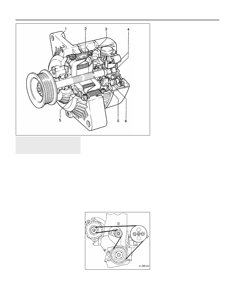
7.5 Sectional view of the Delco-Remy
“compact” series alternator
1 Drive end bracket
2 Stator
3 Rotor
4 Slip rings
5 Fan
6 Rectifier
8.23 Correct routing of the ribbed V-belt
9
Alternator- removal and
refitting
3
Note: Refer to Section 3 before proceeding
Except ‘compact’ series
alternators
Removal
1 Disconnect the battery leads.
2 Disconnect the air trunking from the air
cleaner, and the air box or throttle body, as
applicable, and remove it for improved
access.
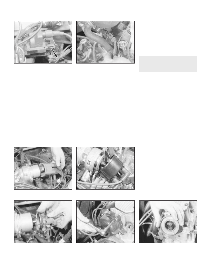
3 Disconnect the wiring plug, or disconnect
the wires from their terminals on the rear of
the alternator, noting their locations (see
illustration).
4 Remove the drivebelt, (Section 8).
5 Unscrew the two mounting bolts and nuts
and recover any washers and insulating
bushes, noting their locations. Note the earth
strap attached to the top mounting bolt (see
illustration).
6 Withdraw the alternator, taking care not to
knock or drop it, as this can cause irreparable
damage.
Refitting
7 Refitting is a reversal of removal,
remembering the following points.
8 Ensure that the earth lead is in place on the
top mounting bolt.
9 Refit and tension the drivebelt, (Section 8).
‘Compact’ series alternators
Removal
10 Disconnect the battery negative lead.
11 Remove the air inlet trunking and, if
necessary for improved access, the air
cleaner assembly.
12 Mark the rotational direction on the
alternator drivebelt with chalk.
13 Using a spanner or socket on the
automatic tensioning roller hexagon turn the
tensioning roller clockwise (as viewed from
the right-hand side of the car) and hold it in
this position. With the drivebelt tension
released, slip the drivebelt off the alternator
pulley, then allow the tensioner to return to its
original position.
14 Disconnect the electrical cable
connections at the rear of the alternator.
15 Undo and remove the alternator lower
mounting bolt, and slacken both upper bolts
that secure the alternator mounting brackets
to the engine.
16 Undo and remove both bolts that secure
the alternator to its mounting brackets, noting
the location of the different length bolts.
Swing the brackets clear and remove the
alternator from the engine.
Refitting
17 Refitting is a reversal of removal. Tighten
the mounting bolts to the specified torque,
and refit the drivebelt as described in
Section 8.
10 Alternator - testing
5
Due to the specialist knowledge and
equipment required to test or service an
alternator, it is recommended that if a fault is
suspected, the vehicle is taken to a dealer or a
specialist. Information is limited to the
inspection and renewal of the brushes.
Should the alternator not charge, or the
system be suspect, the following points may
be checked before seeking further assistance:
a) Check the drivebelt tension, as described
in Section 8
b) Check the condition of the battery and its
connections - see Section 5
c) Inspect all electrical cables and
connections for condition and security
Note that if the alternator is found to be
faulty, it may prove more economical to buy a
factory-reconditioned unit, rather than having
the existing unit overhauled.
11 Alternator brushes - removal,
inspection and refitting
3
Removal
Delco-Remy type (except ‘compact’
series)
1 Remove the alternator, as described in
Section 9
2 Scribe a line across the drive end housing
and the slip ring end housing, to ensure
correct alignment when reassembling.
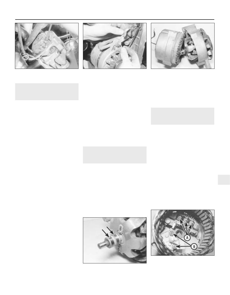
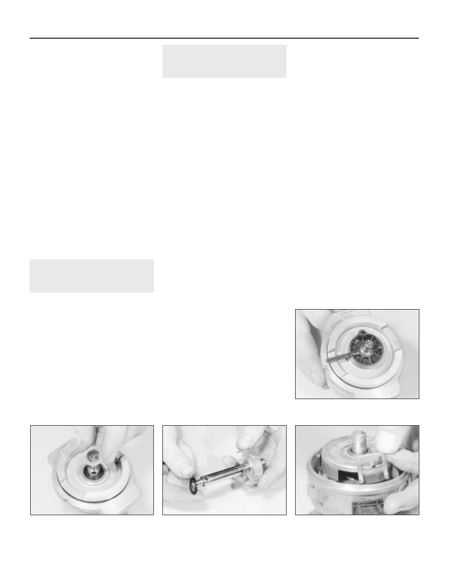
3 Unscrew the three through-bolts, and prise
the drive end housing and rotor away from the
slip ring end housing and stator (see
illustration).
4 Check the condition of the slip rings, and if
necessary clean with a rag or very fine glass
paper (see illustration).
5 Remove the three nuts and washers
securing the stator leads to the rectifier, and
lift away the stator assembly (see
illustration).
Engine electrical systems 5•7
11.3 Separating the drive end housing
from the slip ring end housing - Delco-
Remy alternator
11.4 Alternator slip rings (arrowed) -
Delco-Remy alternator
11.5 Delco-Remy alternator
A Stator lead securing nuts
B Brush holder/voltage regulator
securing screws
9.5 Disconnecting the earth lead from the
top alternator mounting bolt
9.3 Disconnecting the wires from the
terminals on the rear of the alternator -
Delco-Remy alternator
5
6 Remove the terminal screw and lift out the
diode assembly.
7 Extract the two screws securing the brush
holder and voltage regulator to the slip ring
end housing, and remove the brush holder
assembly. Note the insulation washers under
the screw heads.
8 Check that the brushes move freely in their
guides, and that the brush lengths are within
the limits given in the Specifications. If any
doubt exists regarding the condition of the
brushes, the best policy is to renew them.
9 To fit new brushes, unsolder the old brush
leads from the brush holder, and solder on the
new leads in exactly the same place.
10 Check that the new brushes move freely
in the guides.
Refitting
11 Before refitting the brush holder
assembly, retain the brushes in the retracted
position using a stiff piece of wire or a twist
drill.
12 Refit the brush holder assembly so that
the wire or drill protrudes through the slot in
the slip ring end housing, and tighten the
securing screws.
13 Refit the diode assembly and the stator
assembly to the housing, ensuring that the
stator leads are in their correct positions, and
refit the terminal screw and nuts.
14 Assemble the drive end housing and rotor
to the slip ring end housing, ensuring that the
previously made marks are aligned. Insert and
tighten the three through-bolts.
15 Pull the wire or drill, as applicable, from
the slot in the slip ring end housing so that the
brushes rest on the rotor slip rings (see
illustration).
16 Refit the alternator, as described in
Section 9
Bosch type alternator
Removal
17 Disconnect the air trunking from the air
cleaner, and the air box or throttle body, as
applicable, and remove it for improved
access.
18 Disconnect the battery leads.
19 If desired, to improve access further, the
alternator can be removed, as described in
Section 9
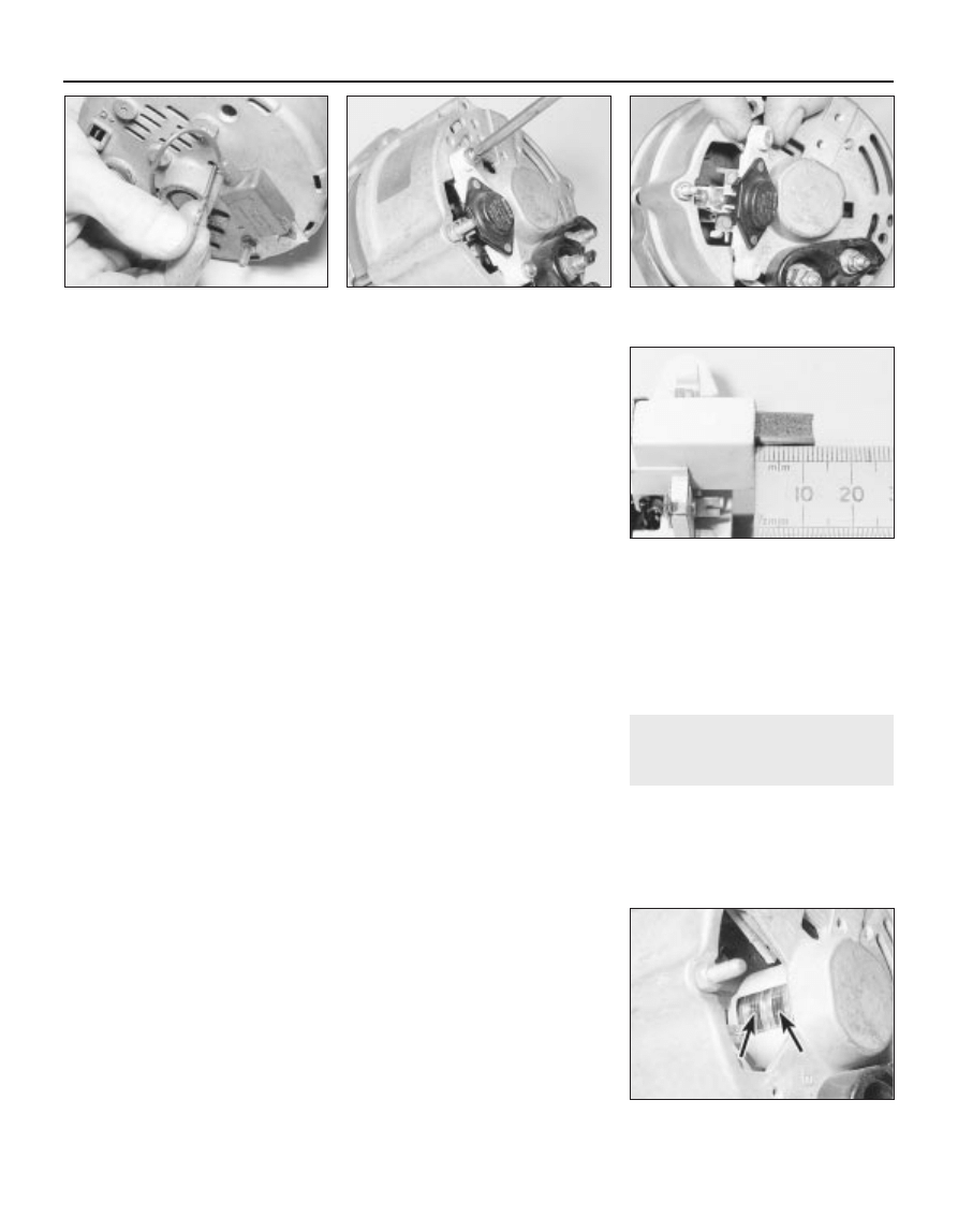
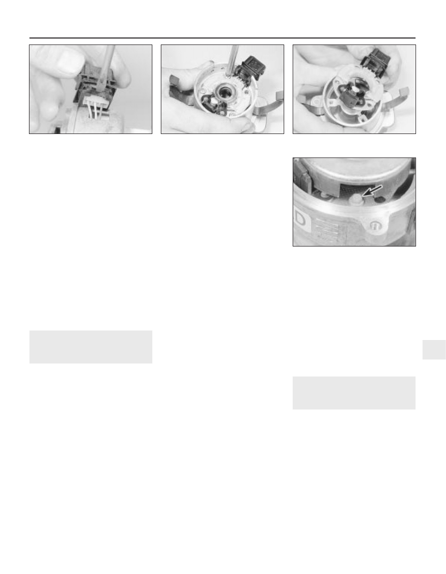
20 Remove the two securing screws, and
withdraw the brush holder/voltage regulator
assembly (see illustrations).
21 Check that the brushes move freely in
their guides, and that the brush lengths are
within the limits given in the Specifications
(see illustration). If any doubt exists
regarding the condition of the brushes, the
best policy is to renew them as follows.
22 Hold the brush wire with a pair of pliers,
and unsolder it from the brush holder. Lift away
the brush. Repeat for the remaining brush.
Refitting
23 Note that whenever new brushes are
fitted, new brush springs should also be fitted.
24 With the new springs fitted to the brush
holder, insert the new brushes, and check that
they move freely in their guides. If they bind,
lightly polish with a very fine file or glass
paper.
25 Solder the brush wire ends to the brush
holder, taking care not to allow solder to pass
to the stranded wire.
26 Check the condition of the slip rings, and
if necessary clean with a rag or very fine glass
paper (see illustration).
27 Refit the brush holder/voltage regulator
assembly, and tighten the securing screws.
28 Where applicable, refit the alternator, as
described in Section 9
29 Reconnect the battery leads.
30 Refit the air trunking.
Delco-Remy “compact” series
Removal
31 Remove the alternator as described in
Section 9.
32 Remove the plastic cover from the rear of
the alternator.
33 Undo the two bolts securing the brush
holder to the rear of the alternator, noting that
one of the bolts also secures the suppression
capacitor.
34 Remove the suppression capacitor then
withdraw the brush holder, noting the flat plug
on the side.
35 Check that the brushes move freely in
their holder and that the brush lengths are
within the limits given in the Specifications. If
any doubt exists regarding the condition of
the brushes, the best policy is to renew them.
36 Check the condition of the slip rings, and
if necessary clean with a rag or very fine glass
paper.
Refitting
37 Refitting the brushes is a reversal of
removal.
12 Starter motor - general
1 The starter motor is mounted at the rear of
the cylinder block, and may be of either
Delco-Remy or Bosch manufacture. Both
makes are of the pre-engaged type, i.e. the
drive pinion is brought into mesh with the
starter ring gear on the flywheel before the
main current is applied.
5•8 Engine electrical systems
11.15 Withdrawing the twist drill used to
retain the brushes -
Delco-Remy alternator
11.20B . . .and withdraw the brush
holder/voltage regulator assembly - Bosch
alternator
11.26 Alternator slip rings (arrowed) -
Bosch alternator
11.21 Measuring the length of an
alternator brush - Bosch alternator
11.20A Remove the securing screws . . .
2 When the starter switch is operated, current
flows from the battery to the solenoid that is
mounted on the starter body. The plunger in
the solenoid moves inwards, so causing a
centrally pivoted lever to push the drive pinion
into mesh with the starter ring gear. When the
solenoid plunger reaches the end of its travel,
it closes an internal contact and full starting
current flows to the starter field coils. The
armature is then able to rotate the crankshaft,
so starting the engine.
3 A special freewheel clutch is fitted to the
starter driven pinion, so that when the engine
fires and starts to operate on its own it does
not drive the starter motor.
4 When the starter switch is released, the
solenoid is de-energised, and a spring moves
the plunger back to its rest position. This
operates the pivoted lever to the withdraw the
drive pinion from engagement with the starter
ring.
13 Starter motor - testing
3
Note: Refer to Section 3 before proceeding
Testing
1 If the starter motor fails to turn the engine
when the switch is operated, and engine
seizure is not the problem, there are several
other possible reasons:
a) The battery is faulty
b) The electrical connections between the
switch, solenoid battery and starter motor
are somewhere failing to pass the
necessary current from the battery
through the starter to earth
c) The solenoid switch is faulty
d) The starter motor is mechanically or
electrically defective
e) The starter motor pinion and/or flywheel
ring gear is badly worn, and in need of
replacement
2 To check the battery, switch on the
headlamps. If they dim after a few seconds,
then the battery is in a discharged state. If the
lamps glow brightly, operate the starter switch
and see what happens to the lamps. If they
dim, then power is reaching the motor, but
failing to turn it. If the starter turns slowly, go
on to the next check.
3 If, when the starter switch is operated, the
lamps stay bright, then insufficient power is
reaching the motor. Disconnect the battery
and the starter/solenoid power connections,
and the engine earth strap, then thoroughly
clean them and refit them. Smear petroleum
jelly around the battery connections to
prevent corrosion. Corroded connections are
the most frequent cause of electrical system
malfunctions.
4 If the preceding checks and cleaning tasks
have been carried out without success, a
clicking noise will probably have been heard
each time the starter switch was operated.
This indicates that the solenoid switch was
operating, but it does not necessarily follow
that the main contacts were closing properly
(if no clicking has been heard from the
solenoid, it is certainly defective). The
solenoid can be checked by connecting a
voltmeter across the main cable connection
on the solenoid and earth. When the switch is
operated, these should be a reading on the
voltmeter. If there is no reading, the solenoid
unit is faulty, and should be renewed.
5 If the starter motor operates, but does not
turn the engine, then it is likely that the starter
pinion and/or flywheel ring gear are badly
worn. If this is the case, the starter motor will
normally be noisy in operation.
6 Finally, if it is established that the solenoid
is not faulty, and 12 volts are reaching the
starter, then the motor itself is faulty, and
should be removed for inspection.
14 Starter motor - removal and
refitting
3
Note: Refer to Section 3 before proceeding
Removal
1 Disconnect the battery negative lead.
2 Apply the handbrake, then jack up the front
of the vehicle, and support securely on axle
stands (see “Jacking and Vehicle Support”)
positioned under the body side members.
3 On DOHC models, remove the engine
undershield, as described in Chapter 11.
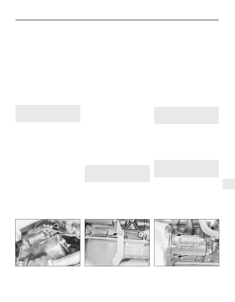
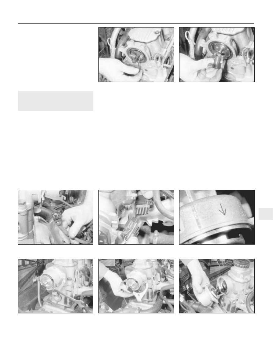
4 Note the wiring connections on the
solenoid, then disconnect them (see
illustration).
5 Where applicable, unscrew the bolt
securing the exhaust bracket and the starter
motor mounting bracket to the cylinder block
(see illustration).
6 Unscrew the two starter motor mounting
bolts. Note that the top bolt on some models
are fitted from the transmission side, and
secures a wiring harness bracket (see
illustration).
7 Withdraw the starter motor.
Refitting
8 Refitting is a reversal of removal, but where
applicable, ensure that the wiring harness
bracket is in place on the top mounting bolt,
and tighten all bolts to the specified torque.
15 Starter motor - overhaul
5
If the starter motor is thought to be suspect,
it should be removed from the vehicle and
taken to an auto-electrician for testing. Most
auto-electricians will be able to supply and fit
brushes at a reasonable cost. However, check
on the cost of repairs before continuing as it
may prove more economical to obtain a new
or exchange motor.
16 Ignition coil - removal, testing
and refitting
3
Note: Refer to Section 3 before proceeding.
An ohmmeter will be required to test the coil
Removal
1 The ignition coil is either a cylindrical metal
canister or a moulded plastic unit. It is
clamped or bolted to the left-hand inner wing
panel, near the suspension strut top mounting
(under the power steering fluid reservoir, on
Engine electrical systems 5•9
14.6 Starter motor securing bolts
(arrowed) - 1.6 litre model
(engine removed)
14.5 Starter motor mounting
bracket/exhaust bracket securing bolt
(arrowed) - 1.6 litre model
14.4 Starter motor and solenoid viewed
from underneath the vehicle. Solenoid
wiring connections arrowed
5
models so equipped). On 14 NV, 16 SV and
18 SV models, the ignition amplifier module is
mounted on the coil’s bracket or baseplate
(see illustration).
2 Disconnect the battery negative lead.
3 Carefully note the LT wiring connections
before disconnecting them (see illustration).
4 Note that on models with power steering,
one of the coil securing bolts also secures the
power steering fluid reservoir bracket.
5 Remove the coil.
6 On models with a cylindrical type coil, the
mounting clamp can be removed from the coil
by loosening the clamp nut.
Testing
7 To test the coil, first disconnect the LT
wiring and the HT lead. Test the coil’s primary
windings by connecting a multi-meter across
the LT terminals (“+” or “15” and “-” or “1”).
Then the secondary windings by testing
across the HT terminal (“4”) and one of the LT
terminals (usually the “-/1” terminal, although
in some cases, either terminal may serve). On
20 XEJ models, results should closely
approximate the specified values. On all other
models, typical primary resistances are less
than 1 ohm, while secondary resistances can
be expected to be in the 4000 to 12 000 ohms
range.
8 If the results obtained differ significantly
from those given, showing windings that are
shorted or open circuit, the coil must be
renewed.
Refitting
9 Refitting is a reversal of removal, however
ensure correct connections. Usually they are
physically different to prevent incorrect
refitting. If not, use the terminal marks or
numbers in conjunction with the relevant
wiring diagram at the back of this manual to
ensure that the connections are correctly
remade. If the connections are reversed, so
will the coil’s polarity be. While the engine
may still run, spark plug life will be reduced
and poor starting and/or misfiring may follow.
10 Where applicable, ensure that the coil
suppresser is in position before refitting the
coil securing bolts.
17 Distributor cap and rotor
arm - removal and refitting
3
Note: Refer to Section 3 before proceeding
Removal
14 NV and 16 SV models
1 Disconnect the battery negative lead.
2 Identify each HT lead for position, so that
the leads can be refitted to their correct
cylinders, then disconnect the leads from the
spark plugs by pulling on the connectors, not
the leads. Similarly, disconnect the HT lead
from the coil. Pull the leads from the clips on
the camshaft cover.
3 On the Bosch distributor, prise away the
two spring clips with a screwdriver, and lift off
the distributor cap. On the Lucas distributor,
unscrew the two small bolts and lift off the
cap (see illustrations).
4 The rotor arm is a push fit on the end of the
distributor shaft.
5 If needed, on the Bosch distributor, the
plastic shield can be pulled from the end of
the distributor, to allow examination of the
distributor components (see illustration).
Other models, where applicable
6 Proceed as described in paragraphs 1 and 2.
7 On DOHC models (except X20 XEV),
unscrew the two securing bolts and withdraw
the spark plug cover from the camshaft cover.
8 Using a Torx socket, unscrew the three
captive securing screws and withdraw the
distributor cap (see illustration).
9 Withdraw the plastic shield from the rotor
arm housing. The shield is fitted in the
housing, with an O-ring seal located in a
groove in its periphery. Ease out the shield,
taking care not to damage the rotor arm (see
illustration).
5•10 Engine electrical systems
16.1 Ignition coil - 1.6 litre models - note
ignition timing basic adjustment coding
plug (arrowed)
17.3A Removing the distributor cap -
1.6 litre model (Bosch distributor) . . .
17.9 Removing the plastic shield from the
rotor arm housing - 2.0 litre model
17.8 Unscrewing a distributor cap
securing screw - 2.0 litre model
17.5 Removing the rotor arm and plastic
shield - 1.6 litre model (Bosch distributor)
17.3B . . .and 1.6 litre models (Lucas
distributor)
16.3 Disconnecting the coil LT wiring plug
- 2.0 litre model
10 Using an Allen key or hexagon bit, extract
the two securing screws and withdraw the
rotor arm, leaving the metal rotor hub in the
housing (see illustrations).
11 Examine the O-ring on the plastic shield,
and renew if necessary.
Refitting
12 Refitting is a reversal of removal, noting
that the rotor arm can only be fitted in one
position. If necessary, turn the metal rotor hub
so that the screw holes align with those in the
rotor arm and the end of the camshaft. Ensure
that the HT leads are correctly reconnected.
18 Distributor (SOHC models) -
removal and refitting
3
Note: Refer to Section 3 before proceeding. A
tachometer and a timing light will be required
to check the ignition timing on completion 14
NV and 16 SV
Removal
1 Disconnect the battery negative lead.
2 Remove the distributor cap, as described in
Section 17.
3 Disconnect the distributor wiring plug (see
illustrations).
4 On 14 NV models, disconnect the vacuum
pipe from the diaphragm unit on the side of
the distributor.
5 If the original distributor is to be refitted,
make alignment marks between the
distributor body and the camshaft housing, so
that the distributor can be refitted in its
original position.
6 Turn the crankshaft. This can be done by
either using a socket or spanner on the
crankshaft pulley bolt, or by engaging top
gear and pushing the vehicle backwards or
forwards. Bring No 1 cylinder to the firing
point. No 1 cylinder is at the firing point when:
a) The relevant timing marks are aligned. On
14 NV models, the pointer on the rear
timing belt cover should be aligned
halfway between the two notches in the
crankshaft pulley. On 16 NV models, the
pointer on the rear timing belt cover
should be aligned with the notch in the
crankshaft pulley
b) The tip of the rotor arm is pointing to the
position occupied by the No 1 cylinder HT
lead terminal in the distributor cap
c) On the Bosch distributor, the rotor arm is
aligned with the notch in the distributor
body (remove the rotor arm and plastic
shield, then refit the rotor arm to check
the alignment with the notch). On the
Lucas distributor, the rotor arm is
approximately aligned with the TDC arrow
stamped in the distributor body (see
illustration).
7 Unscrew the clamp nut and remove the
clamp plate, then withdraw the distributor
from the camshaft housing (see illustrations).
8 If desired, the distributor can be
dismantled, as described in Section 20.
9 Check the condition of the O-ring on the
rear of the distributor body, and renew if
necessary.
Refitting
10 Begin refitting by checking that No 1
cylinder is still at the firing point. The relevant
timing marks should be aligned. If the engine
has been turned whilst the distributor has
Engine electrical systems 5•11
18.6 TDC arrow on the Lucas distributor
body
18.7C . . .and withdraw the distributor
18.7B . . .remove the clamp plate . . .
18.7A Unscrew the clamp nut . . .
18.3B Disconnecting the distributor wiring
on the C16 NZ engine
18.3A Disconnecting the distributor wiring
plug - 1.6 litre model (Bosch distributor)
17.10B . . .and withdraw the rotor arm -
2.0 litre model
17.10A Extract the two securing
screws . . .
5
been removed, check that No 1 cylinder is on
its firing stroke by removing No 1 cylinder
spark plug and placing a finger over the plug
hole. Turn the crankshaft until compression
can be felt, which indicates that No 1 piston is
rising on its compression stroke. Continue
turning the crankshaft until the relevant timing
marks are in alignment.
11 Turn the rotor arm to the position noted in
paragraph 6c, and hold the rotor arm in this
position as the distributor is fitted. Note that
the distributor driveshaft will only engage with
the camshaft in one position. If the original
distributor is being refitted, align the marks
made on the distributor body and camshaft
housing before removal.
12 Refit the clamp plate and nut, but do not
fully tighten the nut at this stage.
13 On the Bosch distributor, remove the rotor
arm, then refit the plastic shield and the rotor
arm.
14 On 14 NV models, reconnect the vacuum
pipe to the diaphragm unit.
15 Reconnect the distributor wiring plug.
16 Refit the distributor cap as described in
Section 17.
17 Reconnect the battery negative lead.
18 Check and if necessary adjust the ignition
timing, as described in Section 21.
19 Distributor (DOHC models),
where applicable - removal
and refitting
3
Removal
1 Disconnect the battery negative lead.
2 Remove the distributor cap, as described in
Section 17.
3 Disconnect the distributor wiring plug.
4 Unscrew the two securing bolts, and
remove the distributor from the cylinder head.
5 Examine the O-ring on the rear of the
distributor, and renew if necessary.
Refitting
6 Refitting is a reversal of removal. However,
note that the distributor should be fitted so
that the wiring plug is positioned on the upper
left-hand side of the distributor body, when
viewed from the distributor cap end.
20 Distributor - dismantling,
inspection and reassembly
3
Note: Before contemplating dismantling of a
distributor, check the cost and availability of
replacement parts. It may prove more
economical to renew the complete distributor
assembly
14 NV models
Dismantling
1 With the distributor removed as described
in Section 18, continue as follows.
2 Pull off the rotor arm, and remove the
plastic shield.
3 The top bearing plate can be removed after
unscrewing the two securing screws, however
(other than the vacuum diaphragm unit), no
spares are available for the distributor and no
adjustments are required.
4 If desired, the vacuum diaphragm unit can
be removed by extracting the two securing
screws and unhooking the operating arm from
the distributor baseplate. Note that the
screws are of differing lengths, the longer
screw also secures one of the distributor cap
clips.
Inspection
5 The vacuum unit can be tested by applying
suction to the vacuum port, and checking that
the operating rod moves into the unit as
suction is applied. Remove the suction, and
check that the operating rod returns to its
original position. If the operating rod does not
move as described, renew the vacuum unit.
6 Check the distributor cap for corrosion of
the segments, and for signs of tracking,
indicated by a thin black line between the
segments. Make sure that the carbon brush in
the centre of the cap moves freely and stands
proud of the surface of the cap. Renew the
cap if necessary.
7 If the metal portion of the rotor arm is badly
burnt or loose, renew it. If slightly burnt or
corroded; it may be cleaned with a fine file.
8 Examine the seal ring at the rear of the
distributor body, and renew if necessary.
Reassembly
9 Reassembly is a reversal of dismantling,
ensuring that the vacuum unit operating arm
is correctly engaged with the peg on the
baseplate, several attempts may be required
to reconnect it.
10 Refit the distributor as described in
Section 18, and then check and if necessary
adjust the ignition timing, as described in
Section 21.
16 SV models
Dismantling
11 With the distributor removed as described
in Section 18, pull off the rotor arm and, on
the Bosch distributor, remove the plastic
shield.
12 Using a pin punch, carefully drive out the
roll pin securing the plastic drive collar to the
rear of the distributor shaft (see illustration).
13 Lift off the drive collar, and remove the
thrustwashers from the end of the shaft (see
illustration).
14 Withdraw the shaft, complete with the
trigger vane, from the distributor body, and
recover the thrustwashers from the shaft (see
illustration).
15 On the Lucas distributor, extract the
spring clip from inside the body, then
withdraw the terminal block. Pull the small
wiring plug from inside the terminal block (see
illustrations).
16 Remove the screws, and lift the sensor
plate from the distributor body (see
illustrations).
5•12 Engine electrical systems
20.15A Removing the spring clip . . .
20.14 Recovering the thrustwashers from
the shaft - 1.6 litre (Bosch distributor)
20.13 Removing the thrustwashers
20.12 Removing the drive collar roll pin -
1.6 litre models (Bosch distributor)
Inspection
17 Examine the distributor cap and rotor arm,
as described in paragraphs 6 and 7. Examine
the O-rings at the rear of the distributor body,
and on the rear of the shaft, and renew if
necessary.
Reassembly
18 Reassembly is a reversal of dismantling,
ensuring that the thrustwashers are correctly
located. Note that the drive collar should be
refitted so that the drive peg on the collar is
aligned with the groove in the top of the
distributor shaft (it is possible to fit the drive
collar 180° out of position).
19 Refit the distributor as described in
Section 18, and then check and if necessary
adjust the ignition timing, as described in
Section 21.
DOHC models (where
applicable)
20 The distributor cap and rotor arm can be
examined as described in paragraphs 6 and 7.
21 Ignition timing - checking and
adjustment
4
Note: Refer to Section 3 before proceeding. A
tachometer and a timing light will be required
during this procedure. For details of ignition
timing adjustment required to operate vehicles
on unleaded petrol, refer to Section 22.
14 NV and 16 SV models
Checking
1 Start the engine and run it until it reaches
normal operating temperature, then switch
off.
2 On 14 NV models, disconnect the vacuum
pipe from the distributor vacuum diaphragm
unit.
3 On all models use a spanner applied to the
crankshaft pulley bolt to rotate the crankshaft
clockwise until the notch in the pulley’s
inboard rim aligns with the pointer protruding
from the oil pump housing. On 14 NV models,
where two notches (indicating 10° and 5°
BTDC respectively) are found, rotate the
crankshaft until the second notch (in the
direction of rotation - i.e. 5° BTDC) aligns. Use
white paint or similar to emphasise the pointer
and notch, to make them easier to see.
4 Connect a timing light to No 1 cylinder
(nearest the timing belt end of the engine) HT
lead, also a tachometer; follow the equipment
manufacturer’s instructions for connection.
5 Start the engine and allow it to idle - the
speed should be between 700 and 1000 rpm.
6 On 14 NV models, aim the timing light at the
pointer and check that it is aligned with the
crankshaft pulley notch.
7 On early 16 SV models, disconnect the
ignition timing basic adjustment coding plug.
This can be identified by a length of Black
wire joining Brown/Red and Brown/Yellow
wires in a connector plug clipped to the wiring
or heater/cooling system hoses beneath the
battery/ignition coil (see illustration, 16.1). This
causes the MSTS-i module to adopt its basic
adjustment mode, sending a constant firing
signal corresponding to 10° BTDC and
eliminating any advance below 2000 rpm. Aim
the timing light at the pointer and check that it
is aligned with the crankshaft pulley notch.
8 On later 16 SV, C 16 NZ and C 16 NZ2
models, the coding plugs are no longer fitted.
For accurate checking, special Vauxhall test
equipment must be used which causes the
MSTS module to adopt its basic adjustment
mode.
9 Without access to such equipment, it is
possible to check and adjust the ignition
timing, accurate results cannot be
guaranteed. Owners are therefore advised to
have this work carried out by a suitably
equipped Vauxhall dealer; at the very least,
make the initial setting yourself and then have
it checked as soon as possible.
10 If you do attempt to check the ignition
timing yourself, note that the fixed reference
mark is now an extended line embossed on
the timing belt lower outer cover.
Adjustment
11 If the notch and pointer are not aligned,
loosen the distributor clamp nut and turn the
distributor body slightly in the required
direction to align.
12 Tighten the distributor clamp nut, and
check that the notch and pointer are still
aligned.
13 Stop the engine, and disconnect the
timing light and tachometer.
14 On 16 SV models, reconnect the basic
adjustment coding plug. On 14 NV models,
reconnect the vacuum pipe to the distributor
vacuum diaphragm unit.
Other models
15 No adjustment of the ignition timing is
possible on 1.8 and 2.0 litre models, as the
adjustment is carried out automatically by the
electronic control module.
16 The ignition timing can be checked by a
Vauxhall dealer using specialist dedicated test
equipment, if a fault is suspected.
22 Ignition timing - adjustment
for use with unleaded petrol
3
14 NV models
1 All models with the 14 NV engine have the
ignition timing adjusted for use with 95 RON
unleaded petrol before they leave the factory,
and no further adjustment is required.
2 Leaded petrol (98 RON) can be used if
desired, with no adverse effects.
1.6, 1.8 and 2.0 SOHC models
Note: Models equipped with a catalytic
converter must be operated on 95 R0N
unleaded petrol at all times, and although an
octane coding plug may be fitted, it should
not be tampered with
3 Models, other than 14 NV, are equipped
with an octane coding plug, which is located
Engine electrical systems 5•13
20.16B . . .and withdraw the sensor plate -
1.6 litre (Bosch distributor)
20.16C Sensor plate screw (arrowed) -
1.6 litre (Lucas distributor)
20.16A Remove the securing screws . . .
20.15B . . .and disconnecting the small
wiring plug - 1.6 litre (Lucas distributor)
5
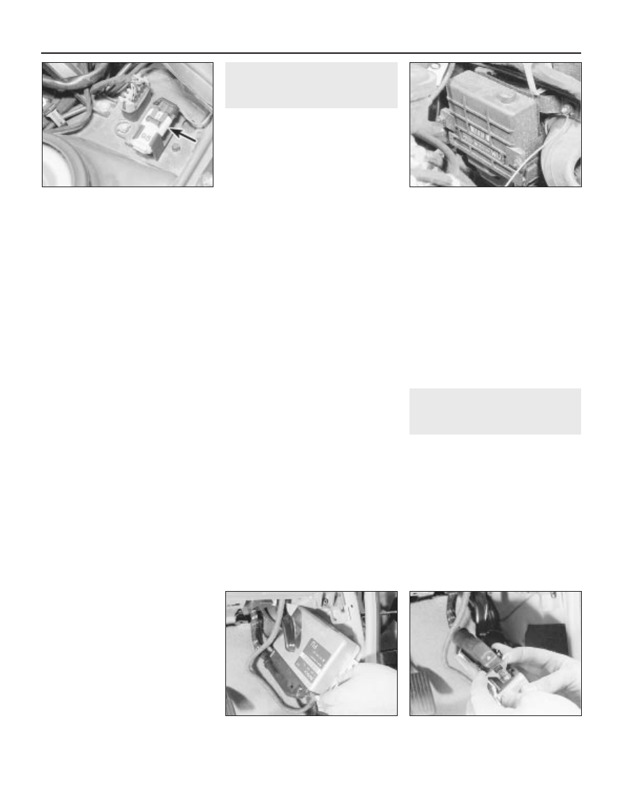
in a clip at the left-hand rear of the engine
compartment (see illustration).
4 The plug is reversible in its connector, and
is marked either “A” or “98” on one side,
which corresponds to the position for use with
98 RON leaded petrol. On the other side either
“B” or “95”, which corresponds to the position
to use with 95 RON unleaded petrol. All
vehicles are set for use with 95 RON unleaded
petrol before they leave the factory.
5 To change the coding for use with a
different type of petrol, first allow the fuel tank
to become practically empty.
6 Fill the fuel tank with the required type of
petrol.
7 Ensure that the ignition is switched off, then
remove the coding plug from its clip and
disconnect the wiring connector.
8 Rotate the plug through 180°, so that the
appropriate octane mark is uppermost (see
paragraph 4), then reconnect the wiring
connector and refit the plug to its clip.
9 Note that using petrol with a higher octane
rating than that set will not cause damage, but
petrol with a lower octane rating than that set
must not be used.
20 XE, C20 XE and X20 XEV
models
10 The ignition coding plug found on these
models is not an octane coding plug
(although its method of operation is similar)
and must not be altered from its factory
setting. Its purpose is to ensure that the
Motronic module uses the correct information,
pre-programmed (or “mapped”) into its
memory, to enable the vehicle to comply with
the relevant national noise and exhaust
emission legislation.
11 On these models, the knock sensor circuit
allows the Motronic module to compensate
for differences in the octane value of the
petrol used, without the need for manual
intervention. Remember, however, that all
catalytic converter-equipped vehicles must
use unleaded petrol only. This means that
these models can use any grade of unleaded
petrol on sale in the UK without the need for
adjustment.
23 Electronic modules - removal
and refitting
3
Note: Refer to Section 3 for precautions to be
observed when working with electronic
modules. Heat sink compound must be used
when refitting the module.
HEI module (14 NV models)
Removal
1 The module is mounted on a metal plate,
beneath the ignition coil, on the left-hand side
of the engine compartment.
2 Remove the ignition coil as described in
Section 16, and slide the coil from its clamp.
3 The module can be removed from the
mounting plate by unscrewing the two
securing screws.
4 Before refitting the module, heat sink
compound should be applied to the mounting
plate to improve heat dissipation. If a new
module is being fitted, it should be supplied
with heat sink compound. Similar compounds
can be bought from DIY electrical shops.
Refitting
5 Refitting is a reversal of removal.
MSTS-i module (1.6 and 1.8 litre
models)
Removal
6 The module is mounted on the engine
compartment bulkhead, above the steering
rack (see illustration).
7 Disconnect the battery negative lead.
8 If desired, for improved access, remove the
air box from the top of the carburettor.
9 Disconnect the wiring plug from the
module.
10 Unscrew the two securing nuts, and
withdraw the module from the bulkhead.
Refitting
11 Refitting is a reversal of removal.
Motronic module
Removal
12 The module is mounted in the driver’s
footwell, behind the side trim panel.
13 Disconnect the battery negative lead.
14 Remove the driver’s footwell side trim
panel, as described in Chapter 11.
15 Unscrew the three module securing
screws, two at the top of the module, and a
single screw at the bottom, and lower the
module from the footwell (see illustration).
16 Release the retaining clip, and disconnect
the module wiring plug (see illustration).
17 Withdraw the module, noting the plastic
insulating sheet on its rear face.
Refitting
18 Refitting is a reversal of removal, but
ensure that the insulating sheet is in place on
the rear face of the module.
24 MSTS-i components -
removal and refitting
3
Note: Refer to Section 3 before proceeding.
Procedures for removal and refitting of the
ignition system components and electronic
module are given elsewhere in the relevant
Sections of this Chapter
Manifold pressure sensor
Removal
1 The sensor is located on the engine
compartment bulkhead, to the left of the
MSTS-i module, under the edge of the
windscreen cowl panel (see illustration).
2 Disconnect the battery negative lead.
5•14 Engine electrical systems
22.3 Octane coding plug (arrowed) -
2.0 litre model
23.15 Lowering the Motronic module from
the footwell - 2.0 litre model
23.16 Releasing the Motronic module
wiring plug clip - 2.0 litre model
23.6 MSTS-i module location -
1.6 litre model
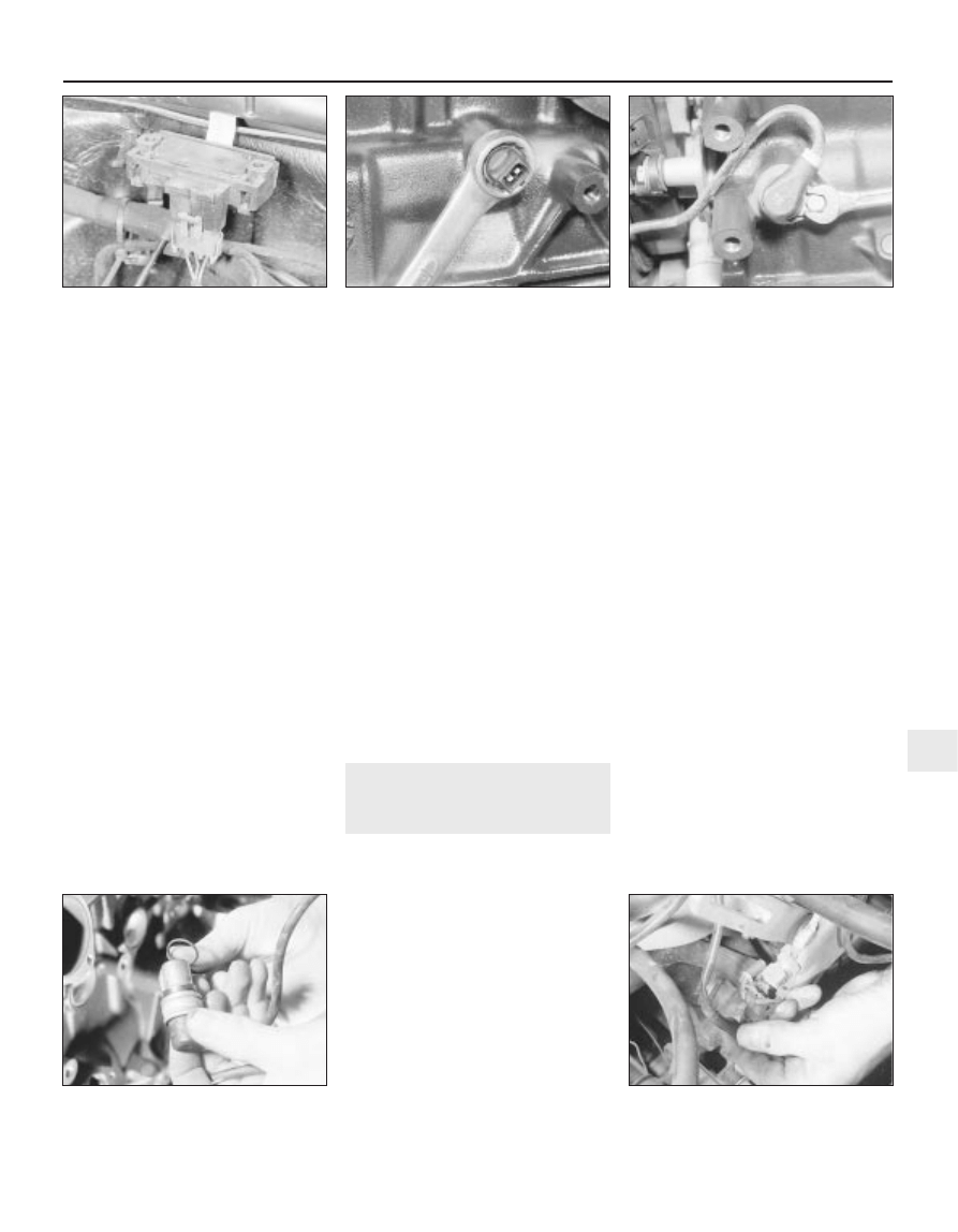
3 Lift up the edge of the windscreen cowl
panel for access to the sensor.
4 Disconnect the sensor wiring plug, and the
vacuum pipe.
5 Pull the pressure sensor upwards to release
it from its bracket, and withdraw it from the
vehicle.
Refitting
6 Refitting is a reversal of removal. However,
on Multec models no fuel vapour trap is fitted.
It is therefore essential that the sensor
vacuum hose is routed so that it falls steadily
from the sensor to the throttle body. This
precaution prevents any fuel droplets being
trapped in the sensor or hose, and allows
them to drain into the inlet port.
Oil temperature sensor
Removal
7 The sensor is screwed into the inlet
manifold side of the cylinder block, next to the
starter motor’s right-hand end.
8 The sensor can be reached quite easily
from above, but if it is to be removed from
beneath, ensure that the handbrake is
applied, and that the vehicle is securely
supported on axle stands (see “Jacking and
Vehicle Support”).
9 Disconnect the battery negative lead.
10 Disconnect the sensor wiring plug.
11 Using a spanner, unscrew the sensor and
remove it (see illustration). Be prepared for
oil spillage, and plug the hole in the cylinder
block to prevent dirt ingress and further oil
loss.
Refitting
12 Refitting is a reversal of removal.
Crankshaft speed/position
sensor (1.8 litre models)
Removal
13 The sensor is located on the exhaust
manifold side of the engine, in the lower
cylinder block behind the oil pump.
14 Disconnect the battery negative lead.
15 Release the relevant outer timing belt
cover securing clips, and unclip the sensor
wiring from the timing belt cover.
16 Disconnect the sensor wiring connector,
noting its location.
17 Unscrew the securing bolt, and withdraw
the sensor from the cylinder block (see
illustration).
18 Examine the sensor sealing ring, and
renew if necessary (see illustration).
Refitting
19 Refitting is a reversal of removal, ensuring
that the sensor wiring is correctly located on
the timing belt cover, and that the wiring
connector is correctly located.
25 Motronic system
components - removal and
refitting
3
Note: Refer to Section 3 before proceeding.
Procedures for removal and refitting of the
ignition system components and electronic
module are given elsewhere in the relevant
Sections of this Chapter. Removal and
refitting procedures for all fuel injection
system components are given in Chapter 4B
Coolant temperature sensor
Removal
1 On all except 20 XEJ models, the sensor is
located in the end of the thermostat housing,
on the inlet manifold side of the engine.
2 On 20 XEJ models, the sensor is located in
the thermostat housing, on the exhaust
manifold side of the engine.
3 Disconnect the battery negative lead.
4 Partially drain the cooling system, as
described in Chapter 3.
5 Disconnect the sensor wiring plug (see
illustration).
6 Using a spanner, unscrew the sensor and
withdraw it from the thermostat housing.
Refitting
7 Refitting is a reversal of removal.
8 On completion, top-up the cooling system,
as described in Chapter 3.
Knock sensor (DOHC models)
Removal
9 The sensor is located at the lower inlet
manifold side of the cylinder block, below the
idle speed adjuster, and is only accessible
from below the vehicle.
10 Disconnect the battery negative lead.
11 Apply the handbrake, then jack up the
front of the vehicle, and support securely on
axle stands (see “Jacking and Vehicle
Support”) placed under the body side
members.
12 Remove the engine undershield, as
described in Chapter 11.
13 Disconnect the sensor wiring plug.
14 Unscrew the securing bolt, and withdraw
the sensor from the cylinder block.
Refitting
15 Refitting is a reversal of removal, but note
that the mating faces of the sensor and
cylinder block must be cleaned thoroughly
before fitting the sensor.
Engine electrical systems 5•15
24.17 Unscrewing the crankshaft
speed/position sensor securing bolt -
1.8 litre model
25.5 Disconnecting the coolant
temperature sensor wiring plug - 2.0 litre
model (alternator removed)
24.18 Examine the crankshaft
speed/position sensor sealing ring -
1.8 litre model
24.11 Unscrewing the MSTS-i oil
temperature sensor - 1.6 litre model
(engine removed)
24.1 MSTS-i manifold pressure sensor -
1.6 litre model
5

26 DIS module - removal and
refitting
3
Note: Refer to Section 3 before proceeding.
Removal
1 Disconnect the battery negative lead.
2 Disconnect the HT leads from the module
terminals noting their locations to ensure
correct refitting. Note that the HT lead cylinder
numbers are stamped on the module, next to
each terminal, and similar numbers appear on
each HT lead.
3 Disconnect the module wiring plug.
4 On X16 SZ engines, undo the three screws
and remove the module from the camshaft
housing. On C20 XE engines, undo the bolts
securing the DIS module mounting bracket to
the cylinder head and remove the module and
bracket. Note the installed position of DIS
module on its mounting bracket, undo the four
securing screws and separate the module
from the bracket.
Refitting
5 Refitting is a reversal of removal.
27 Camshaft phase sensor (C20
XE engine) - removal and
refitting
3
Note: Refer to Section 3 before proceeding.
Removal
1 The camshaft phase sensor is mounted on
the end of the cylinder head in the position
normally occupied by the distributor.
2 Disconnect the battery negative lead.
3 Disconnect the wiring plug then undo the
phase sensor securing bolts.
4 Withdraw the phase sensor from the
cylinder head, then undo the bolt and remove
the phase sensor disc from the end of the
camshaft.
Refitting
5 Refitting is a reversal of removal.
5•16 Engine electrical systems
Wyszukiwarka
Podobne podstrony:
podrecznik 2 18 03 05
regul praw stan wyjątk 05
05 Badanie diagnostyczneid 5649 ppt
Podstawy zarządzania wykład rozdział 05
05 Odwzorowanie podstawowych obiektów rysunkowych
05 Instrukcje warunkoweid 5533 ppt
05 K5Z7
05 GEOLOGIA jezior iatr morza
05 IG 4id 5703 ppt
05 xml domid 5979 ppt
Świecie 14 05 2005
Wykł 05 Ruch drgający
TD 05
6 Zagrozenia biosfery 07 05 05
więcej podobnych podstron