4C•1
Chapter 4 Part C: Fuel and exhaust systems -
multi-point fuel injection models
Contents
ACAV intake system (1998 cc 16-valve models) - general
information, removal and refitting 19
Accelerator cable - removal, refitting and adjustment 3
Accelerator pedal - removal and refitting 4
Air cleaner assembly and intake ducts - removal and refitting 2
Air cleaner filter element renewal See Chapter 1
Bosch Motronic M1.3 system components - removal and refitting . . . 15
Bosch Motronic MP3.1 system components - removal and refitting .. 14
Bosch Motronic MP3.2 system components - removal and refitting .. 16
Bosch Motronic MP5.1 system components - removal and refitting .. 13
Exhaust manifold - removal and refitting 20
Exhaust system - general information, removal and refitting 21
Exhaust system check See Chapter 1
Fuel filter - renewal See Chapter 1
Degrees of difficulty
Fuel gauge sender unit - removal and refitting 9
Fuel injection system - depressurisation 7
Fuel injection system - testing and adjustment 11
Fuel injection systems - general information 6
Fuel pump - removal and refitting 8
Fuel tank - removal and refitting 10
General fuel system checks See Chapter 1
General information and precautions 1
Idle speed and mixture adjustment See Chapter 1
Inlet manifold - removal and refitting 18
Magneti Marelli 8P.20 system components - removal and refitting . 17
Throttle housing - removal and refitting 12
Unleaded petrol - general information and usage 5
Easy, suitable for
novice with little
experience
Fairly easy, suitable
for beginner with
some experience
Fairly difficult, suitable
for competent DIY
mechanic
Difficult, suitable for
experienced DIY
mechanic
Very difficult,
suitable for expert DIY
or professional
Specifications
System type
1761 cc (LFZ engine) models Bosch Motronic MP5.1
1905 cc non-catalyst (D6E engine) models Bosch Motronic MP3.1
1905 cc catalyst (DKZ engine) models Bosch Motronic M1.3
1998 cc 8-valve (RFX engine) models Magneti Marelli 8P.20
1998 cc 16-valve (RFY engine) models Bosch Motronic MP3.2
Note: Refer to Chapter 2B for further information on engine code identification
Fuel system data
Fuel pump type Electric, immersed in tank
Fuel pump regulated constant pressure (at specified idle speed):
Bosch Motronic systems 2.5 to 3.0 bars (depending on system)
Magneti Marelli system 2.0 bars
Specified idle speed:
1905 cc models 850 ± 50 rpm (adjustable via screw on the throttle housing)
All other models -. 850 ± 50 rpm (not adjustable -controlled by ECU)
Idle mixture CO content:
1905 cc non-catalyst (D6E engine) models 1.0 to 2.0 % (adjustable via screw on mixture adjustment -
potentiometer)
1905 cc catalyst (DKZ engine) models, and all other models Less than 1.0 % (not adjustable- controlled by ECU)
Recommended fuel
Minimum octane rating:
1905 cc non-catalyst (D6E engine) models 95 RON unleaded (UK unleaded premium) or
97 RON leaded (UK "4-star")
1905 cc catalyst (DKZ engine) models, and all other models 95 RON unleaded (UK unleaded premium).
Leaded fuel must not be used
4C•2 Fuel and exhaust systems - multi-point fuel injection models
Torque wrench settings Nm ibf ft
Inlet manifold nuts 22 16
Exhaust manifold nuts 22 16
Exhaust system fasteners:
Front pipe-to-manifold nuts 10 7
Clamping ring nut(s):
Clamps secured with one bolt 25 18
Clamps secured with two bolts 20 15
The fuel supply system consists of a fuel
tank (which is mounted under the rear of the
car, with an electric fuel pump immersed in it),
a fuel filter, fuel feed and return lines. The fuel
pump supplies fuel to the fuel rail, which acts
as a reservoir for the four fuel injectors which
inject fuel into the inlet tracts. The fuel filter
incorporated in the feed line from the pump to
the fuel rail ensures that the fuel supplied to
the injectors is clean.
Refer to Section 6 for further information on
the operation of each fuel injection system,
and to Section 21 for information on the
exhaust system. Throughout this Section, it is
also occasionally necessary to identify
vehicles by their engine codes rather than by
engine capacity alone. Refer to the relevant
Part of Chapter 2 for further information on
engine code identification.
Warning: Many of the procedures
in this Chapter require the
removal of fuel lines and
connections, which may result in some fuel
spillage. Before carrying out any operation
on the fuel system, refer to the precautions
given in "Safety first!" at the beginning of
this manual, and follow them implicitly.
Petrol is a highly-dangerous and volatile
liquid, and the precautions necessary when
handling it cannot be overstressed.
Note: Residual pressure will remain in the fuel
lines long after the vehicle was last used. When
disconnecting any fuel line, first depressurise
the fuel system as described in Section 7.
Removal
1761 cc and 1998 cc 8-valve models
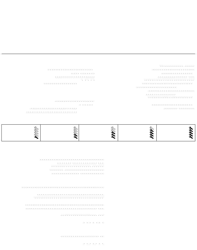
1 Slacken the retaining clip, and disconnect
the breather hose(s) from the side of the air
2.1a On 1761 cc and 1998 cc 8-valve
models, slacken the clips and disconnect
the hose(s) from the air cleaner-to-throttle
body d u c t . . .
2.1b . . . then slacken the duct retaining
c l i p s . . .
cleaner-to-throttle housing duct. Slacken the
duct retaining clips, then disconnect it from
the air cleaner and throttle housing, and
remove it from the vehicle (see illustrations).
Where necessary, recover the rubber sealing
ring from the throttle housing.
2 Release the two retaining clips, then
slacken and remove the two retaining screws
from the front of the cylinder head cover, and
remove the air cleaner element cover from the
head. Withdraw the air cleaner element.
3 To remove the intake duct, undo the bolt
securing the rear section of the duct to the
end of the cylinder head, then slacken the
retaining clip and disconnect the duct from
the cylinder head cover. Undo the nut
securing the front of the duct to the left-hand
wing valance, and manoeuvre the duct out of
the engine compartment (see illustration).
1905 cc models
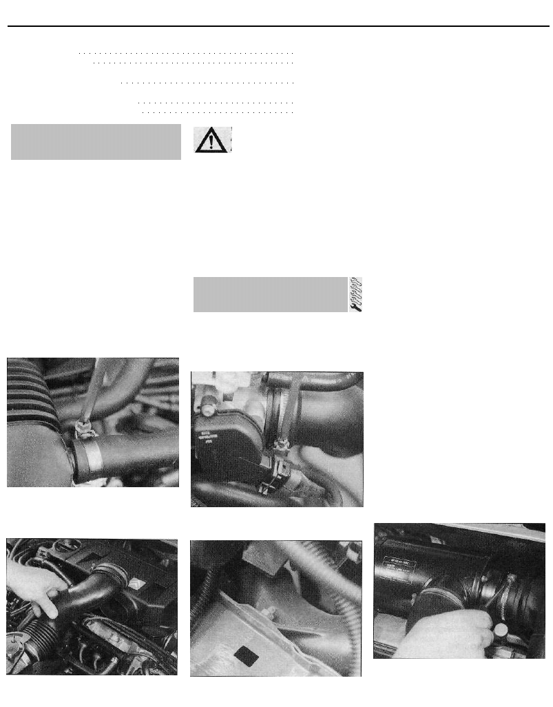
4 Slacken the retaining clips, and disconnect
the intake duct and throttle housing duct from
the air cleaner (see illustration).
5 Slacken and remove the bolt securing the
air cleaner right-hand mounting bracket to the
rear of the cylinder head, and the two nuts
securing the housing to its left-hand mounting
bracket. Lift the air cleaner housing out of the
engine compartment (see illustrations).
6 To remove the intake duct, undo the nut(s)
securing the front of the duct to the left-hand
wing valance, then undo the nut securing the
duct to its mounting bracket (where fitted).
Disconnect the duct from the air cleaner
housing, if not already having done so, and
remove it from the vehicle.
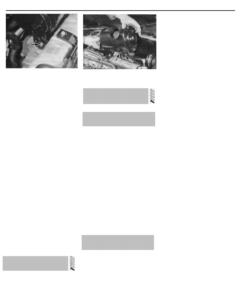
7 On models without a catalytic converter
(Bosch Motronic MP3.1 system), to remove
the air cleaner-to-throttle housing duct, first
2.1c . . . and remove the duct from the
engine compartment
2.3 Intake duct front retaining nut
2.4 On 1905 cc models, slacken the
retaining clips and disconnect the intake
and throttle housing ducts from the air
c l e a n e r . . .
1 General information and
precautions
2 Air cleaner assembly and intake
ducts - removal and refitting
Fuel and exhaust systems - multi-point fuel injection models 4C•3
2.5a . . . then undo the retaining bolt
(arrowed)...
disconnect the wiring connector from the
intake air temperature sensor. Slacken the
retaining clip, and disconnect the vacuum
pipe from the front of the duct. Slacken the
clips, disconnect the duct from the air cleaner
and throttle housings, and remove the duct.
Recover the rubber sealing ring from the
throttle housing.
8 On models with a catalytic converter
(Bosch Motronic M1.3 system), the air
cleaner-to-throttle housing duct is in two
sections, with the airflow meter situated in the
middle. Each section can be removed once its
retaining clips have been slackened, noting
that, in the case of the front duct section, it
will also be necessary to disconnect the
vacuum pipe.
1998 cc 16-valve models
9 Slacken the retaining clip, and disconnect
the air cleaner-to-throttle housing duct from
the throttle housing. Recover the rubber
sealing ring. Release the retaining clips, and
disconnect the breather hose(s) from the duct.
10 Apply the handbrake, then jack up the
front of the vehicle and support it on axle
stands.
11 From underneath the vehicle, slacken and
remove the retaining nuts securing the
resonator chamber to the side of the air
cleaner housing, and remove the chamber.
12 Undo the air cleaner housing retaining
bolt(s), and remove the housing and duct
assembly from underneath the vehicle.
Refitting
13 Refitting is a reversal of the removal
procedure, ensuring that all hoses are
properly reconnected, and that all ducts are
correctly seated and securely held by their
retaining clips.
3 Accelerator cable - removal,
refitting and adjustment
1 Refer to Chapter 4A, Section 7, substituting
"throttle housing" for all references to the
carburettor. On models with automatic
transmission, once the accelerator cable is
correctly adjusted, check the kickdown cable
adjustment as described in Chapter 7B.
2.5b . . . and the two retaining nuts
(locations arrowed), then remove the air
cleaner housing
Refer to Chapter 4A, Section 8.
Note: The information given in this Chapter is
correct at the time of writing. If updated
information is thought to be required, check
with a Citroen dealer. If travelling abroad,
consult one of the motoring organisations (or a
similar authority) for advice on the fuel available.
1 The fuel recommended by Citroen is given
in the Specifications Section of this Chapter,
followed by the equivalent petrol currently on
sale in the UK.
2 All Citroen ZX multi-point injection models
are designed to run on fuel with a minimum
octane rating of 95 (RON). With the exception
of those 1905 cc models without a catalytic
converter (Bosch Motronic MP3.1 system), all
models have a catalytic converter, and so
must be run on unleaded fuel only. Under no
circumstances should leaded fuel (UK "4-star")
be used, as this may damage the converter.
However, 1905 cc models without a catalytic
converter can use either unleaded or leaded
fuel without modification or risk of damage.
3 Super unleaded petrol (98 octane) can also
be used in all models if wished, though there
is no advantage in doing so.
Bosch Motronic MP5.1 system -
1761 cc models
1 The Bosch Motronic engine management
(fuel injection/ignition) system is fitted to all
1761 cc models. The system incorporates a
closed-loop catalytic converter and an
evaporative emission control system, and
complies with the very latest emission control
standards. Refer to Chapter 5 for information
on the ignition side of the system; the fuel side
of the system operates as follows.
2 The fuel pump (which is immersed in the
fuel tank) supplies fuel from the tank to the
fuel rail, via a filter mounted underneath the
rear of the vehicle. Fuel supply pressure is
controlled by the pressure regulator in the fuel
rail. When the optimum operating pressure of
the fuel system is exceeded, the regulator
allows excess fuel to return to the tank.
3 The electrical control system consists of the
ECU, along with the following sensors:
(a) Throttle potentiometer - informs the ECU
of the throttle position, and the rate of
throttle opening/closing.
(b) Coolant temperature sensor - informs the
ECU of engine temperature.
(c) Intake air temperature sensor - informs
the ECU of the temperature of the air
passing through the throttle housing.
(d) Lambda sensor - informs the ECU of the
oxygen content of the exhaust gases
(explained in greater detail in Part D of
this Chapter).
(e) Crankshaft sensor - informs the ECU of
the crankshaft position and speed of
rotation.
(f) Manifold Absolute Pressure (MAP) sensor
- informs the ECU of the load on the
engine (expressed in terms of inlet
manifold vacuum).
(g) Vehicle speed sensor - informs the ECU
of the vehicle speed.
4 All the above signals are analysed by the ECU,
and it selects the fuelling response appropriate to
those values. The ECU controls the fuel injectors
(varying the pulse width - the length of time the
injectors are held open - to provide a richer or
weaker mixture, as appropriate). The mixture is
constantly varied by the ECU, to provide the best
setting for cranking, starting (with either a hot or
cold engine), warm-up, idle, cruising, and
acceleration.
5 The ECU also has full control over the
engine idle speed, via an auxiliary air valve
which bypasses the throttle valve. When the
throttle valve is closed, the ECU controls the
opening of the valve, which in turn regulates
the amount of air entering the manifold, and
so controls the idle speed.
6 The ECU also controls the exhaust and
evaporative emission control systems, which
are described in detail in Part D of this
Chapter.
7 An electric heating element is fitted to the
throttle housing; the heater is supplied with
current by the ECU, and warms the throttle
housing on cold starts to prevent possible
icing of the throttle valve.
8 If there is an abnormality in any of the
readings obtained from either the coolant
temperature sensor, the intake air
temperature sensor or the lambda sensor, the
ECU enters its back-up mode. In this event, it
ignores the abnormal sensor signal, and
assumes a pre-programmed value which will
allow the engine to continue running (albeit at
reduced efficiency). If the ECU enters this
back-up mode, the warning light on the
4 Accelerator pedal -
removal and refitting
5 Unleaded petrol - general
information and usage
6 Fuel injection systems - general
information
4C•4 Fuel and exhaust systems - multi-point fuel injection models
instrument panel will come on, and the
relevant fault code will be stored in the ECU
memory.
9 If the warning light comes on, the vehicle
should be taken to a Citroen dealer at the
earliest opportunity. A complete test of the
engine management system can then be
carried out, using a special electronic
diagnostic test unit which is simply plugged
into the system's diagnostic connector.
Bosch Motronic MP3.1 system -
1905 cc models without a catalytic
converter
10 The Bosch Motronic MP3.1 engine
management (fuel injection/ignition) system is
fitted to all 1905 cc models without a catalytic
converter (D6E engine). Refer to Chapter 5 for
information on the ignition side of the system.
11 The MP3.1 system is very similar in
operation to the MP5.1 system described
above, noting the following differences:
(a) On the MP3.1 system, there is no lambda
(oxygen) sensor or vehicle speed sensor.
The idle mixture (exhaust gas CO content)
can be manually adjusted via the mixture
adjustment potentiometer.
(b) The ECU has no control over the engine
idle speed; the idle speed is manually set
using a screw on the throttle housing. An
auxiliary air valve (not to be confused with
the idle speed control valve on the MP5.1
system) is incorporated in the system, but
this is used purely as an additional air
supply on cold starts and during the
warm-up period.
(c) There is no heating element fitted to the
throttle housing. The engine coolant is
circulated around the housing, to warm
the housing after cold starts.
(d) There is no evaporative emission control
system.
Bosch Motronic Ml.3 system -
1905 cc models with a catalytic
converter
12 The Bosch Motronic M1.3 engine
management (fuel injection/ignition) system is
fitted to all 1905 cc models with a catalytic
converter (DKZ engine). Refer to Chapter 5 for
information on the ignition side of the system.
13 The M1.3 system is very similar in
operation to the MP5.1 system described
above, noting the following differences:
(a) On the M1.3 system, there is no vehicle
speed sensor or MAP sensor. In place of
the MAP sensor, an airflow meter is fitted
to the throttle housing intake duct, to
inform the ECU of the volume of air
passing through the duct and entering the
throttle housing.
(b) The ECU has no control over the engine
idle speed; the idle speed is manually set
using a screw on the throttle housing. An
auxiliary air valve (not to be confused with
the idle speed control valve on the MP5.1
system) is incorporated in the system, but
this is used purely as an additional air
supply on cold starts and during the
warm-up period.
(c) There is no heating element fitted to the
throttle housing. The engine coolant is
circulated around the housing, to warm
the housing after cold starts.
Bosch Motronic MP3.2 system -
1998 cc 16-valve models
14 The Bosch Motronic MP3.2 engine
management (fuel injection/ignition) system is
fitted to all 1998 cc 16-valve models. Refer to
Chapter 5 for information on the ignition side
of the system.
15 The MP3.2 system is very similar in
operation to the MP5.1 system described
above, noting that, in addition to the sensors
listed, a camshaft position sensor is
incorporated into the system. The camshaft
position sensor is fitted to the left-hand end of
the cylinder head, directly over the top of the
inlet camshaft, and informs the ECU when
No 1 cylinder is at Top Dead Centre (TDC).
16 The MP3.2 system differs from all the
other fuel injection systems in that it is a
"sequential" system. This means that each of
the four fuel injectors is triggered individually,
just before the inlet valve on that particular
cylinder opens. This is in contrast to all other
systems, on which all four injectors are
triggered simultaneously; this happens once
for every revolution of the crankshaft.
Magneti Marelli 8P.20 system -
1998 cc 8-valve models
17 The Magneti Marelli 8P.20 engine
management (fuel injection/ignition) system is
fitted to all 1998 cc 8-valve models. Refer to
Chapter 5 for information on the ignition side
of the system.
18 The system is very similar in operation to
the Bosch MP5.1 system described above,
apart from the idle speed control system.
19 On the Magneti Marelli system, the idle
speed is controlled by the ECU via a stepper
motor fitted to the throttle housing. The motor
has a pushrod controlling the opening of an
air passage which bypasses the throttle valve.
When the throttle valve is closed, the ECU
controls the movement of the motor pushrod,
which regulates the amount of air which flows
through the throttle housing passage, so
controlling the idle speed. The bypass
passage is also used as an additional air
supply during cold starting.
Note: Refer to the warning note in Section 1
before proceeding.
Warning: The following
procedure will merely relieve the
pressure in the fuel system -
remember that fuel will still be
present in the system components and
take precautions accordingly before
disconnecting any of them.
1 The fuel system referred to in this Section is
defined as the tank-mounted fuel pump, the
fuel filter, the fuel injectors, the fuel rail and
the pressure regulator, and the metal pipes
and flexible hoses of the fuel lines between
these components. All these contain fuel
which will be under pressure while the engine
is running, and/or while the ignition is
switched on. The pressure will remain for
some time after the ignition has been
switched off, and it must be relieved in a
controlled fashion when any of these
components are disturbed for servicing work.
2 Disconnect the battery negative terminal.
3 Place a container beneath the
connection/union to be disconnected, and
have a large rag ready to soak up any
escaping fuel not being caught by the
container.
4 Slowly loosen the connection or union nut
to avoid a sudden release of pressure, and
position the rag around the connection, to
catch any fuel spray which may be expelled.
Once the pressure is released, disconnect the
fuel line. Plug the pipe ends, to minimise fuel
loss and prevent the entry of dirt into the fuel
system.
8 Fuel pump -
removal and refitting
Note: Refer to the warning note in Section 1
before proceeding.
Removal
1 Disconnect the battery negative lead.
2 For access to the fuel pump, tilt or remove
the rear seats, as described in Chapter 11.
3 Using a screwdriver, carefully prise the
plastic access cover from the floor, to expose
the fuel pump (located under the right-hand
cover).
4 Disconnect the wiring connector from the
fuel pump, and tape the connector to the
vehicle body, to prevent it disappearing
behind the tank.
5 Mark the hoses for identification purposes,
then slacken the feed and return hose
retaining clips. Where the original crimped-
type Citroen hose clips are fitted, cut the clips
and discard them; use standard worm-drive
hose clips on refitting. Disconnect both hoses
from the top of the pump, and plug the hose
ends.
6 Noting the alignment marks on the tank,
pump cover and the locking ring, unscrew the
ring and remove it from the tank. This is best
accomplished by using a screwdriver on the
raised ribs of the locking ring, as follows.
Carefully tap the screwdriver to turn the ring
anti-clockwise until it can be unscrewed by
hand.
7 Displace the pump cover, then reach into the
tank and unclip the pump from the tank base.
Carefully lift the fuel pump assembly out of the
fuel tank, taking care not to damage the filter,
or to spill fuel onto the interior of the vehicle.
7 Fuel system - depressurisation
Fuel and exhaust systems - multi-point fuel injection models 4C•5
Recover the rubber sealing ring and discard it -
a new one must be used on refitting.
8 Note that the fuel pump is only available as
a complete assembly - no components are
available separately.
Refitting
9 Ensure the fuel pump pick-up filter is clean
and free of debris. Fit the new sealing ring to
the top of the fuel tank.
10 Carefully manoeuvre the pump assembly
into the fuel tank, and clip it into position in
the base of the tank.
11 Align the mark on the fuel pump cover
with the centre of the three alignment marks
on the fuel tank, then refit the locking ring.
Securely tighten the locking ring, and check
that the locking ring, pump cover and tank
marks are all correctly aligned.
12 Reconnect the feed and return hoses to
the top of the fuel pump, using the marks
made on removal to ensure they correctly
reconnected, and securely tighten their
retaining clips.
13 Reconnect the pump wiring connector.
14 Reconnect the battery negative terminal,
and start the engine. Check the fuel pump
feed and return hoses unions for signs of
leakage.
15 If all is well, refit the plastic access cover,
and tilt or refit the rear seat as described in
Chapter 11 (as applicable).
9 Fuel gauge sender unit -
removal and refitting
Refer to Chapter 4A, Section 5, noting that
there are no fuel pipe connections to the
sender unit.
10 Fuel tank -
removal and refitting
Refer to Chapter 4A, Section 6, noting that
it will be necessary to depressurise the fuel
system as the feed and return hoses are
disconnected (see Section 7). It will also be
necessary to disconnect the wiring connector
from the fuel pump before lowering the tank
out of position (see Section 8).
11 Fuel injection system -
testing and adjustment
Testing
1 If a fault appears in the fuel injection
system, first ensure that all the system wiring
connectors are securely connected and free
of corrosion. Ensure that the fault is not due to
poor maintenance; ie, check that the air
cleaner filter element is clean, the spark plugs
are in good condition and correctly gapped,
the cylinder compression pressures are
correct, the ignition timing is correct, and that
the engine breather hoses are clear and
undamaged, referring to Chapters 1, 2 and 5
for further information.
2 If these checks fail to reveal the cause of
the problem, the vehicle should be taken to a
suitably-equipped Citroen dealer for testing. A
wiring block connector is incorporated in the
engine management circuit, into which a
special electronic diagnostic tester can be
plugged; the connector is located inside either
the engine compartment junction box, or
directly in front of the box (see illustration).
The tester will locate the fault quickly and
simply, alleviating the need to test all the
system components individually, which is a
time-consuming operation that carries a risk
of damaging the ECU.
Adjustment
3 On 1905 cc models without a catalytic
converter (Motronic MP3.1 system), both the
idle speed and idle mixture (exhaust gas CO
level) are adjustable. On 1905 cc models with
a catalytic converter (Motronic M1.3 system),
only the idle speed is adjustable (mixture
adjustment is not possible). Refer to Chapter
1 for information on adjustment procedures.
4 On all other models, experienced home
mechanics with a considerable amount of skill
and equipment (including a tachometer and
an accurately calibrated exhaust gas analyser)
may be able to check the exhaust CO level
and the idle speed. However, if these are
found to be in need of adjustment, the car
must be taken to a suitably-equipped Citroen
dealer for further testing. Neither the mixture
adjustment (exhaust gas CO level) nor the idle
speed are adjustable, and should either be
incorrect, a fault must be present in the fuel
injection system.
Removal
1 Disconnect the battery negative terminal.
1761 cc and 1998 cc 8-valve models
2 Remove the air cleaner-to-throttle housing
duct as described in Section 2.
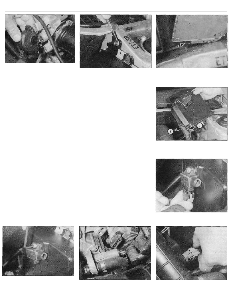
3 Disconnect the accelerator inner cable from
the throttle cam, then withdraw the outer
cable from the mounting bracket, along with
its flat washer and spring clip (see
illustration).
4 Depress the retaining clips, and disconnect
the wiring connectors from the throttle
potentiometer, the electric heating element,
the air temperature sensor and idle control
stepper motor (as applicable) (see
illustration).
5 Release the retaining clips (where fitted),
and disconnect all the relevant vacuum and
breather hoses from the throttle housing (see
illustration). Make identification marks on the
hoses, to ensure they are connected correctly
on refitting.
6 Slacken and remove the three retaining
screws, and remove the throttle housing from
11.2 Diagnostic wiring connector located
in the engine compartment junction box
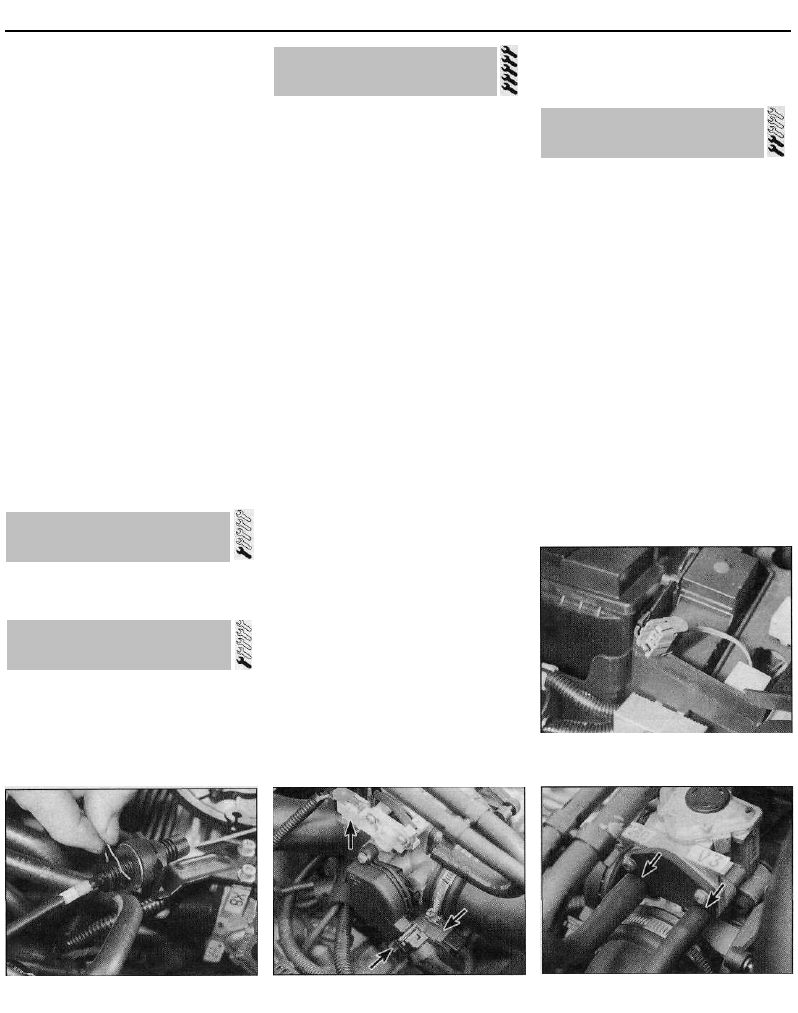
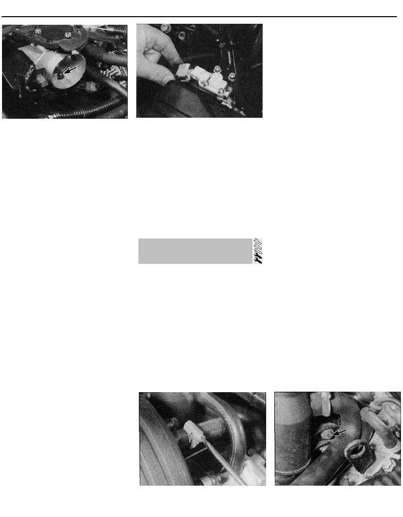
12.3 Disconnecting the accelerator cable -
1998 cc 8-valve model
12.4 Throttle housing wiring connectors
(arrowed) -1761 cc model
12.5 Throttle housing vacuum hoses
(arrowed) - 1761 cc model
12 Throttle housing -
removal and refitting
4C•6 Fuel and exhaust systems - multi-point fuel injection models
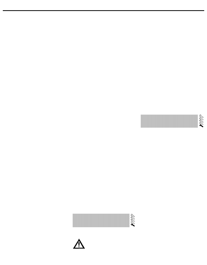
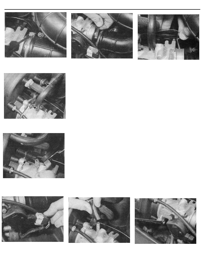
12.7a On 1905 cc models, slacken the
retaining clip . . .
12.8b . . . then undo the retaining nut and
bolt (arrowed)...
12.8c . . . and remove the bracket.
Remove the flat washer (arrowed) for
safekeeping
12.7b . . . then disconnect the duct and
recover the rubber sealing ring
the inlet manifold. Remove the O-ring from the
manifold, and discard it - a new one must be
used on refitting.
1905 cc models
7 Slacken the retaining clip, disconnect the
intake duct from the end of the throttle
housing, and recover the rubber sealing ring
(where fitted) (see illustrations).
8 Disconnect the accelerator inner cable from
the throttle cam. Slacken and remove the bolt
and nut securing the outer cable mounting
bracket to the manifold, then withdraw the
bracket. Remove the flat washer from the end
of the cable for safekeeping (see
illustrations). On models with automatic
transmission, free the kickdown cable from
the throttle cam.
9 Depress the retaining clip, and disconnect
the wiring connector from the throttle
potentiometer (see illustration).
10 Relieve any pressure in the cooling
system by unscrewing the filler cap. Slacken
the retaining clips, and disconnect the two
coolant hoses from the base of the throttle
housing. Plug the hose ends, working quickly
to minimise coolant loss.
11 Release the retaining clips (where fitted),
and disconnect all the relevant vacuum and
breather hose(s) from the throttle housing
(see illustration). Make identification marks
on the hoses, to ensure they are correctly
reconnected on refitting.
12 Undo the remaining two retaining nuts,
12.8a Disconnect the accelerator cable
from the throttle cam . . .
and remove the throttle housing from the
manifold. On early models, it will also be
necessary to remove the nut and bolt securing
the base of the housing to its support bracket
(see illustration). Remove the O-ring from the
manifold, and discard it - a new one must be
used on refitting.
1998 cc 16-valve models
13 Slacken the retaining clip, disconnect the
intake duct from the end of the throttle
housing, and recover the rubber sealing ring
(where fitted).
14 Disconnect the accelerator inner cable
from the throttle cam, then withdraw the outer
cable from the mounting bracket, along with
its flat washer and spring clip.
15 Depress the retaining clips, and
disconnect the wiring connectors from the
throttle potentiometer, the electric heating
element, and the air temperature sensor.
16 Slacken the retaining clips (where fitted),
and disconnect all the relevant vacuum and
breather hoses from the throttle housing.
Make identification marks on the hoses, to
ensure they are connected correctly on
refitting.
17 Slacken the nut securing the throttle
housing lower mounting bracket to the
transmission housing.
18 Slacken and remove the housing retaining
screws, then remove the throttle housing from
the inlet manifold. Remove the O-ring from the
manifold, and discard it - a new one must be
used on refitting.
12.9 Disconnect the throttle potentiometer
wiring connector . . .
12.11 . . . and the breather hose from the
throttle housing
12.12 Undo the two remaining nuts, and
remove the throttle housing
Fuel and exhaust systems - multi-point fuel injection models 4C•7
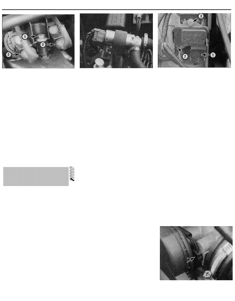
13.3 Wiring tray retaining bolt (1) and
injector wiring connectors (2) - 1761 cc
model
Refitting
19 Refitting is a reversal of the removal
procedure, noting the following points:
(a) Fit a new O-ring to the manifold, then refit
the throttle housing and securely tighten
its retaining nuts or screws (as
applicable).
(b) Ensure all hoses are correctly
reconnected and, where necessary, are
securely held in position by the retaining
clips.
(c) Ensure all wiring is correctly routed, and
that the connectors are securely
reconnected.
(d) On completion, adjust the accelerator
cable as described in Section 3.
(e) On 1905 cc models, check the coolant
level and top up if necessary (Chapter 1).
13 Bosch Motronic MP5.1
system components -
removal and refitting
Note: Check parts availability with a Citroen
dealer prior to removing individual components.
At the time of writing, certain components are
only available as part of a larger assembly - eg
the throttle potentiometer is only available as
part of the throttle housing assembly.
Fuel injectors
Note: Refer to the warning note in Section 1
before proceeding. If a faulty injector is
suspected, before condemning the injector, it
is worth trying the effect of one of the
proprietary injector-cleaning treatments.
1 Disconnect the battery negative terminal.
2 Remove the air cleaner-to-throttle housing
duct as described in Section 2.
3 Undo the two bolts securing the wiring tray
to the top of the manifold, and position the
tray clear of the injectors (see illustration).
4 Depress the retaining clip(s), and
disconnect the wiring connector(s) from the
injector(s).
5 Slacken the retaining screw, and remove
the injector retaining plate; Nos 1 and 2
injectors are retained by one plate, Nos 3 and
4 by another.
13.17 Idle speed auxiliary air valve -
1761 cc model
6 Place a wad of clean rag over the injector,
to catch any fuel spray which may be
released, then carefully ease the relevant
injector(s) out of the manifold. Remove the O-
ring from the end of each disturbed injector,
and discard it - these must be renewed
whenever they are disturbed.
7 On refitting the injectors, fit a new O-ring to
the end of each injector. Apply a smear of
engine oil to the O-ring, to aid installation,
then ease the injector(s) back into position in
the manifold.
8 Ensure each injector connector is pointing
upwards, then refit the retaining plate and
securely tighten its retaining screw.
Reconnect the wiring connector(s) to the
injector(s).
9 Refit the wiring tray to the top of the
manifold, and securely tighten its retaining
bolts.
10 Refit the air cleaner-to-throttle body duct,
and reconnect the battery. Start the engine,
and check the injectors for signs of leakage.
Fuel pressure regulator
11 Refer to Section 14.
Throttle potentiometer
12 The throttle potentiometer is fitted to the
right-hand side of the throttle housing. To
remove the potentiometer, first disconnect the
battery negative terminal.
13 Depress the retaining clip, and disconnect
the potentiometer wiring connector.
14 Slacken and remove the two retaining
screws, and remove the potentiometer from
the throttle housing.
15 Refitting is the reverse of removal,
ensuring that the potentiometer is correctly
engaged with the throttle valve spindle.
Electronic Control Unit (ECU)
16 Refer to Section 17.
Idle speed auxiliary air valve
17 The idle speed auxiliary air valve is
mounted on the left-hand end of the cylinder
head, directly above the ignition HT coil (see
illustration). To remove the valve, first
disconnect the battery negative terminal.
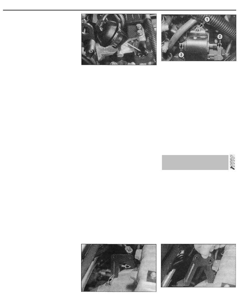
13.22 MAP sensor wiring connector (1),
vacuum hose (2) and retaining nut (3) -
1761 cc model
18 Depress the retaining clip, and disconnect
the wiring connector from the top of the valve.
19 Slacken the retaining clip(s), and
disconnect the two hoses from the valve.
Slide the valve rubber retaining clip off its
pegs, and remove the valve from the engine
compartment.
20 Refitting is a reverse of the removal
sequence, ensuring that the hoses are
securely reconnected.
Manifold absolute pressure (MAP)
sensor
21 The MAP sensor is situated on the right-
hand side of the engine compartment,
attached to the engine/transmission mounting
point. To remove the MAP sensor, first
disconnect the battery negative terminal.
22 Depress the retaining clip, disconnect the
wiring connector from the sensor, then
disconnect the vacuum hose from the sensor
(see illustration).
23 Undo the retaining bolt, and remove the
sensor from the engine compartment.
24 Refitting is a reverse of the removal
procedure.
Coolant temperature sensor
25 Refer to Chapter 3, Section 6.
Intake air temperature sensor
26 The intake air temperature sensor is
located in the throttle housing (see
illustration).
13.26 On 1761 cc models, the intake air
temperature sensor (arrowed) is situated
behind the throttle potentiometer
4C•8 Fuel and exhaust systems - multi-point fuel injection models
14.3 Where original crimped-type Citroen
hose clips are fitted, cut them and discard
27 To remove the sensor, first remove the
throttle potentiometer as described in
paragraphs 12 to 14.
28 Depress the retaining clip, and disconnect
the wiring connector from the air temperature
sensor.
29 Remove the screw securing the sensor
connector to the top of the throttle housing,
then carefully ease the sensor out of position
and remove it from the throttle housing.
Examine the sensor O-ring for signs of
damage or deterioration, and renew if
necessary.
30 Refitting is a reversal of the removal
procedure, using a new O-ring where
necessary, and ensuring that the throttle
potentiometer is correctly engaged with the
throttle valve spindle.
Crankshaft sensor
31 Refer to Section 14.
Fuel injection system relay unit
32 Refer to Section 14.
Throttle housing heating element
33 Refer to Section 17.
Note: Check parts availability with a Citroen
dealer prior to removing individual
components. At the time of writing, certain
components are only available as part of a
larger assembly - eg the throttle potentiometer
is only available as part of the throttle housing
assembly.
Fuel rail and injectors
Note: Refer to the warning note in Section 1
before proceeding. If a faulty injector is
suspected, before condemning the injector, it
is worth trying the effect of one of the
proprietary injector-cleaning treatments.
1 Disconnect the battery negative terminal.
2 Disconnect the vacuum pipe from the fuel
pressure regulator.
3 Bearing in mind the information given in
14.4 Disconnecting the injector wiring
connectors -1905 cc model
Section 7, slacken the retaining clips, and
disconnect the fuel feed and return hoses
from the either end of the fuel rail. Where the
original crimped-type Citroen hose clips are
still fitted, cut them off and discard them; use
standard worm-drive hose clips on refitting
(see illustration).
4 Depress the retaining tangs, and
disconnect the wiring connectors from the
four injectors (see illustration).
5 Slacken and remove the two fuel rail
retaining bolts, then carefully ease the fuel rail
and injector assembly out from the inlet
manifold and remove it from the vehicle (see
illustration). Remove the O-rings from the
end of each injector, and discard them; these
must be renewed whenever they are
disturbed.
6 Slide out the retaining clip(s), and remove
the relevant injector(s) from the fuel rail.
Remove the upper O-ring from each injector
as it is removed, and discard it; all O-rings
must be renewed once they have been
disturbed.
7 Refitting is a reversal of the removal
procedure, noting the following points:
(a) Fit new O-rings to all disturbed injectors.
(b) Apply a smear of engine oil to the O-rings
to aid installation, then ease the injectors
and fuel rail into position, ensuring that
none of the O-rings are displaced.
(c) On completion, start the engine and
check for fuel leaks.
14.5 On 1905 cc models, the fuel rail is
retained by two bolts (arrowed)
Fuel pressure regulator
Note: Refer to the warning note in Section 1
before proceeding.
8 Disconnect the vacuum pipe from the
regulator.
9 Place a wad of clean rag over the regulator,
to catch any fuel spray which may be
released. Remove the retaining clip, and slide
the regulator out of the end of the fuel rail (see
illustration).
10 Refitting is a reversal of the removal
procedure. Examine the regulator seal for
signs of damage or deterioration, and renew if
necessary.
Throttle potentiometer
11 Disconnect the battery negative terminal.
12 Depress the retaining clip, and disconnect
the wiring connector from the throttle
potentiometer.
13 Slacken and remove the two retaining
screws, then disengage the potentiometer
from the throttle valve spindle and remove it
from the vehicle (see illustration).
14 Refitting is a reverse of the removal
procedure, ensuring that the potentiometer is
correctly engaged with the throttle valve
spindle (see illustration).
Electronic Control Unit (ECU)
15 The ECU is located in the rear left-hand
corner of the engine compartment. To remove
14.9 Fuel pressure regulator retaining clip
(arrowed) can be prised out of position
using a flat-bladed screwdriver
14.13 Throttle potentiometer is secured to
the throttle housing by two screws
14 Bosch Motronic MP3.1
system components -
removal and refitting
Fuel and exhaust systems - multi-point fuel injection models 4C•9
14.14 On refitting, ensure that the
potentiometer is correctly engaged with 14.17a Undo the ECU upper retaining
the throttle valve spindle (arrowed) b o l t . . .
the ECU, first disconnect the battery negative
terminal.
16 Depress the retaining clip, and disconnect
the wiring connector from the idle mixture
adjustment potentiometer.
17 Slacken and remove the upper bolt
securing the ECU mounting bracket to the
wing valance, then loosen the lower bolt
(there is no need to remove the lower bolt, as
the mounting is slotted). Withdraw the bracket
and ECU assembly from the engine
compartment, disconnecting the wiring
connector and vacuum pipe from the ECU as
they become accessible (see illustrations).
18 With the assembly on the bench, undo the
bolts securing the ECU to the bracket, and
separate the two components.
19 Refitting is a reversal of the removal
procedure, ensuring that the wiring connector
and vacuum pipe are securely reconnected.
Idle speed mixture adjustment
potentiometer
20 The idle speed mixture adjustment
potentiometer is situated in the rear left-hand
corner of the engine compartment, mounted
onto the ECU bracket. To remove it, first
disconnect the battery negative terminal.
21 Depress the retaining tangs and
disconnect the wiring connector, then undo the
retaining screw and remove the potentiometer
from the vehicle (see illustrations).
22 Refitting is the reverse of removal. On
completion, check and, if necessary, adjust
14.21b . . . then undo the retaining screw
and remove the idle speed mixture
potentiometer
the idle mixture setting (exhaust gas CO level)
as described in Chapter 1.
Auxiliary air valve
23 The auxiliary air valve is mounted on the
left-hand end of the cylinder head, directly
beneath the ignition HT coil (see illustration).
24 To improve access to the valve, remove
the ignition HT coil as described in Chapter 5.
25 Depress the retaining clip, and disconnect
the wiring connector from the air valve.
26 Slacken the retaining clips, and
disconnect the vacuum hoses from either end
of the auxiliary air valve.
27 Undo the two retaining bolts, and remove
the auxiliary air valve from the engine
compartment.
28 Refitting is a reversal of the removal
procedure.
Manifold absolute pressure (MAP)
sensor
29 The MAP sensor is an integral part of the
electronic control unit (ECU). Refer to
paragraphs 15 to 19 for removal and refitting
details.
Coolant temperature sensor
30 Refer to Chapter 3, Section 6.
Intake air temperature sensor
31 The intake air temperature sensor is
located in the air cleaner-to-throttle housing
duct (see illustration). To remove the sensor,
first disconnect the battery negative terminal.
14.17b . . . and loosen its lower mounting
nut. The lower mounting is slotted to ease
removal
14.17c Remove the ECU, disconnecting its
vacuum hose (1) and wiring connector (2)
as they become accessible
14.21a Disconnect the wiring
connector...
14.23 Auxiliary air valve location - wiring
connector arrowed
14.31 Disconnecting the wiring connector
from the intake air temperature sensor
4C•10 Fuel and exhaust systems - multi-point fuel injection models
32 Disconnect the wiring connector, then
unscrew the sensor from the intake duct and
remove it from the vehicle.
33 Refitting is the reverse of removal.
Crankshaft sensor
34 The crankshaft sensor is mounted on top
of the transmission housing, next to the left-
hand end of the cylinder block. To remove the
sensor, first disconnect the battery negative
terminal.
35 Access to the sensor is poor, and it will be
necessary to remove the battery and battery
tray (see Chapter 5) and/or the intake duct
assembly (see Section 2) to improve access
(depending on model and specification). On
some models, it will also be necessary to
remove the metal plate from the top of the
transmission housing; the plate is retained by
one of the engine-to-transmission bolts, and
by a second bolt securing the plate to the top
of the transmission.
36 Trace the wiring back from the sensor to
its wiring connector, and disconnect it from
the main wiring harness. Undo the retaining
bolt, and remove the sensor from the top of
the transmission housing.
37 Refitting is a reversal of the removal
procedure, ensuring that the sensor wiring is
correctly routed.
Fuel injection system relay unit
38 The fuel injection system relay unit is
mounted on the front of the engine
compartment junction box. To remove the
relay unit, first disconnect the battery negative
terminal.
39 Open up the junction box lid, then slacken
and remove the relay mounting nut and
washer. Release the retaining clip, then
disconnect the wiring connector and remove
the relay unit from the engine compartment
(see illustrations).
40 Refitting is the reverse of removal.
Note: Check parts availability with a Citroen
dealer prior to removing individual
components. At the time of writing, certain
components are only available as part of a
larger assembly, eg the throttle switch is only
available as part of the throttle housing
assembly.
Fuel rail and injectors
1 The fuel rail and injectors can be removed
as described in Section 14, noting that it will
first be necessary to remove the ignition HT
coil as described in Chapter 5.
Fuel pressure regulator
2 Refer to Section 14.
14.39a Disconnect the wiring
connector...
Throttle switch
3 Disconnect the battery negative terminal.
4 Depress the retaining clip, and disconnect
the wiring connector from the throttle
potentiometer.
5 Slacken and remove the two retaining
screws, then disengage the potentiometer
from the throttle valve spindle and remove it
from the vehicle.
6 When refitting the switch, ensure it is
correctly engaged with the throttle valve
spindle, and lightly tighten its retaining
screws. Slowly operate the throttle valve
whilst listening to the switch; the switch
should click as soon as the throttle valve
starts to open, and again just before it is fully
closed. Position the switch until this is so,
then securely tighten its retaining screws.
7 Reconnect the wiring connector, and
reconnect the battery.
Electronic Control Unit (ECU)
8 Refer to the information given in Section 14,
noting that there is no idle mixture adjustment
potentiometer to disconnect.
Airflow meter
9 Disconnect the battery negative terminal.
10 Depress the retaining clip, and disconnect
the wiring connector from the airflow meter.
11 Slacken the retaining clips, and
disconnect the intake ducts from either end of
the airflow meter.
12 Slacken and remove the retaining nuts
and bolts, and remove the airflow meter from
the engine compartment.
13 Refitting is a reverse of the removal
procedure.
Auxiliary air valve
14 The auxiliary air valve is mounted on the
left-hand end of the cylinder head, directly
beneath the airflow meter.
15 To improve access to the valve, remove
the airflow meter as described above.
16 Depress the retaining clip, and disconnect
the wiring connector from the air valve.
17 Slacken the retaining clips, and
disconnect the vacuum hoses from either end
of the auxiliary air valve.
14.39b . . . then undo the retaining bolt,
and remove the fuel injection relay unit
from the front of the junction box
18 Undo the two retaining bolts, and remove
the auxiliary air valve from the engine
compartment.
19 Refitting is a reversal of the removal
procedure.
Manifold absolute pressure (MAP)
sensor
20 Refer to Section 14.
Coolant temperature sensor
21 Refer to Chapter 3, Section 6.
Intake air temperature sensor
22 The intake air temperature sensor is an
integral part of the airflow meter, and is not
available separately. Refer to paragraphs 9
to 13 for airflow meter removal and refitting
details.
Crankshaft sensor
23 Refer to Section 14.
Fuel injection system relay unit
24 Refer to Section 14.
16 Bosch Motronic MP3.2
system components -
removal and refitting
Note: Check parts availability with a Citroen
dealer prior to removing individual
components. At the time of writing, certain
components are only available as part of a
larger assembly, eg the throttle potentiometer
is only available as part of the throttle housing
assembly.
Fuel rail and injectors
Note: Refer to the warning note in Section 1
before proceeding. If a faulty injector is
suspected, before condemning the injector, it
is worth trying the effect of one of the
proprietary injector-cleaning treatments.
1 Disconnect the battery negative terminal.
2 Disconnect the vacuum pipe from the fuel
pressure regulator.
3 Bearing in mind the information given in
Section 7, slacken the retaining clips, and
disconnect the fuel feed and return hoses
15 Bosch Motronic M1.3 system
components -
removal and refitting
Fuel and exhaust systems - multi-point fuel injection models 4C•11
16.8 Fuel pressure regulator location -
1998 cc 16-valve models
from the right-hand end of the fuel rail. Where
the original crimped-type Citroen hose clips
are still fitted, cut them off and discard them;
use standard worm-drive hose clips on
refitting.
4 Depress the retaining tangs, and
disconnect the wiring connectors from the
four injectors. To avoid the possibility of the
wiring connectors being incorrectly
reconnected on refitting, mark each
connector with its cylinder number (No 1 is at
the transmission end of the engine).
5 Slacken and remove the two fuel rail
retaining bolts, then carefully ease the fuel rail
and injector assembly out from the inlet
manifold, and remove it from the vehicle.
Remove the O-rings from the end of each
injector, and discard them; these must be
renewed whenever they are disturbed.
6 Slide out the retaining clip(s), and remove
the relevant injector(s) from the fuel rail.
Remove the upper O-ring from each injector
as it is removed, and discard it; all O-rings
must be renewed once they have been
disturbed.
7 Refitting is a reversal of the removal
procedure, noting the following points:
(a) Fit new O-rings to all disturbed injectors.
(b) Apply a smear of engine oil to the O-rings
to aid installation, then ease the injectors
and fuel rail into position, ensuring that
none of the O-rings are displaced.
(c) Using the marks made on removal, ensure
that all the injector wiring connectors are
correctly reconnected.
(d) On completion, start the engine and
check for fuel leaks.
Fuel pressure regulator
8 Refer to Section 14 (see illustration).
Throttle potentiometer
9 The throttle potentiometer is fitted to the
rear of the throttle housing.
10 To improve access to the potentiometer,
remove the throttle housing as described in
Section 12.
11 Undo the two retaining screws, and
remove the potentiometer from the base of
the throttle housing.
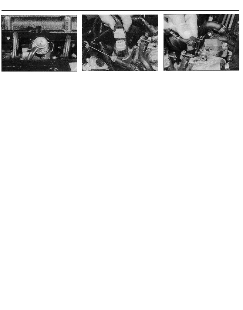
16.16 Disconnecting the wiring connector
from the idle speed auxiliary air valve -
1998 cc 16-valve models
12 On refitting, ensure that the potentiometer
is correctly engaged with the throttle valve
spindle, and securely tighten its retaining
screws.
13 Refit the throttle housing as described in
Section 12.
Electronic Control Unit (ECU)
14 Refer to Section 17.
Idle speed auxiliary air valve
15 The idle speed auxiliary air valve is
mounted on the left-hand end of the inlet
manifold, directly in front of the braking
system vacuum pump. To remove the valve,
first disconnect the battery negative terminal.
16 Depress the retaining clip, and disconnect
the wiring connector from the top of the valve
(see illustration).
17 Free the valve from its mounting rubber,
then disconnect the two hoses from the base
of the valve and manoeuvre the valve out from
the engine compartment.
18 Refitting is a reverse of the removal
sequence, ensuring that the hoses are
securely reconnected.
Manifold absolute pressure (MAP)
sensor
19 The MAP sensor is an integral part of the
electronic control unit (ECU). Refer to Section
17 for ECU removal and refitting details.
Coolant temperature sensor
20 Refer to Chapter 3, Section 6.
Intake air temperature sensor
21 The intake air temperature sensor is
located in the throttle housing.
22 To remove the sensor, first remove the
throttle potentiometer as described in
paragraphs 9 to 11.
23 Trace the wiring back from the sensor to
its wiring connector, and remove the screw
securing the connector to the top of the
throttle housing.
24 Carefully ease the sensor out of position,
and remove it from the throttle housing.
Examine the sensor O-ring for signs of
damage or deterioration, and renew if
necessary.
16.27 Disconnecting the wiring connector
from the camshaft position sensor -
1998 cc 16-valve models
25 Refitting is a reversal of the removal
procedure, using a new O-ring where
necessary. Refit the potentiometer as
described in paragraphs 12 and 13.
Camshaft position sensor
26 The camshaft position sensor is located
on the left-hand end of the cylinder head,
directly over the end of the inlet camshaft. To
remove the sensor, first disconnect the
battery negative terminal.
27 Depress the retaining clip, and disconnect
the wiring connector from the sensor (see
illustration).
28 Undo the retaining screw, and withdraw
the sensor from the end of the cylinder head.
Examine its O-ring for signs of damage or
deterioration, and renew if necessary.
29 Refitting is a reversal of the removal
procedure, using a new O-ring where
necessary.
Crankshaft sensor
30 Refer to Section 14.
Fuel injection system relay unit
31 Refer to Section 14.
Vehicle speed sensor
32 The vehicle speed sensor is an integral
part of the transmission speedometer drive
assembly. Refer to Chapter 7A for removal
and refitting details.
Knock sensor
33 The knock sensor is screwed onto the
rear face of the cylinder block.
34 To gain access to the sensor, firmly apply
the handbrake, then jack up the front of the
vehicle and support it on axle stands. Access
to the sensor can then be gained from
underneath the vehicle.
35 Trace the wiring back from the sensor to
its wiring connector, and disconnect it from
the main loom.
36 Slacken and remove the bolt securing the
sensor to the cylinder block, and remove it
from underneath the vehicle.
37 Refitting is a reversal of the removal
procedure, ensuring that the sensor wiring is
4C•12 Fuel and exhaust systems - multi-point fuel injection models
17.5 Fuel feed hose connection (1),
injector wiring connectors (2) and (two of
the three) fuel rail retaining bolts (3) -
1998 cc 8-valve models
correctly routed and its retaining bolt securely
tightened.
Throttle housing heating element
38 The throttle housing heating element is
fitted to the top of the throttle housing, and is
an integral part of the throttle housing. At the
time of writing, no information is available on
element removal and refitting. Refer to your
Citroen dealer for further information.
Note: Check parts availability with a Citroen
dealer prior to removing individual
components. At the time of writing, certain
components are only available as part of a
larger assembly, eg the throttle potentiometer
is only available as part of the throttle housing
assembly.
Fuel rail and injectors
Note: Refer to the warning note in Section 1
before proceeding. If a faulty injector is
suspected, before condemning the injector, it
is worth trying the effect of one of the
proprietary injector-cleaning treatments.
1 Disconnect the battery negative terminal.
2 Remove the air cleaner-to-throttle housing
duct, using the information given in Section 2.
3 Disconnect the vacuum pipe from the fuel
pressure regulator.
4 Release the retaining clip, and free the
various hoses from the top of the fuel rail.
5 Bearing in mind the information given in
Section 7, slacken the retaining clip, and
disconnect the fuel feed and return hoses
from the ends of the fuel rail. Where the
original crimped-type Citroen hose clips are
still fitted, cut them off and discard them; use
standard worm-drive hose clips on refitting
(see illustration).
6 Depress the retaining clips, and disconnect
the wiring connectors from the four injectors.
7 Slacken and remove the three fuel rail
retaining bolts, then carefully ease the fuel rail
and injector assembly out from the inlet
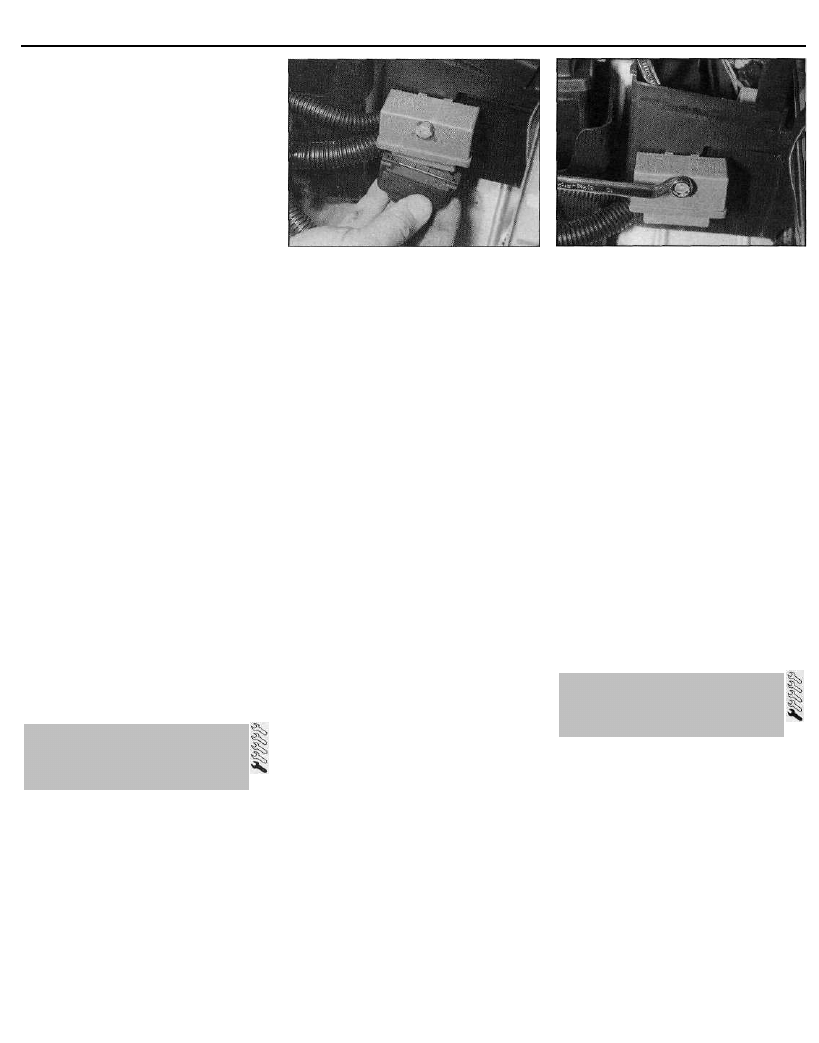
17.16 Unclip the lid from the plastic box to
gain access to the ECU
manifold, and remove it from the vehicle.
Remove the O-rings from the end of each
injector, and discard them; these must be
renewed whenever they are disturbed.
8 Slide out the retaining clip(s), and remove
the relevant injector(s) from the fuel rail.
Remove the upper O-ring from each injector
as it is removed, and discard it; all O-rings
must be renewed once they have been
disturbed.
9 Refitting is a reversal of the removal
procedure, noting the following points:
(a) Fit new O-rings to all disturbed injectors.
(b) Apply a smear of engine oil to the O-rings
to aid installation, then ease the injectors
and fuel rail into position, ensuring that
none of the O-rings are displaced.
(c) On completion, start the engine and
check for fuel leaks.
Fuel pressure regulator
10 Refer to Section 14.
Throttle potentiometer
11 Remove the throttle housing as described
in Section 12.
12 Undo the two retaining screws, and
remove the potentiometer from the base of
the throttle housing.
13 On refitting, ensure that the potentiometer
is correctly engaged with the throttle valve
spindle, and securely tighten its retaining
screws.
14 Refit the throttle housing as described in
Section 12.
Electronic control unit (ECU)
15 The ECU is situated inside its own
protective plastic box, located directly behind
the battery, on the left-hand side of the engine
compartment. To remove the ECU, first
disconnect the battery negative terminal.
16 Unclip the lid from the plastic box, and
slide the ECU and mounting plate out of
position (see illustration).
17 Disconnect the wiring connector from the
ECU, then undo the retaining screws and
remove the ECU from the engine
compartment.
17.21 Idle speed control stepper motor is
retained by two screws (arrowed) - 1998 cc
8-valve models
18 Refitting is the reverse of removal,
ensuring that the wiring connector is securely
reconnected.
Idle speed control stepper motor
19 The idle speed control stepper motor is
located on the right-hand side of the throttle
housing assembly. To remove the motor, first
disconnect the battery negative terminal.
20 Release the retaining clip, and disconnect
the wiring connector from the motor.
21 Slacken and remove the two retaining
screws, and withdraw the motor from the
throttle housing (see illustration).
22 Refitting is a reversal of the removal
procedure.
Manifold absolute pressure (MAP)
sensor
23 The MAP sensor is situated on the right-
hand side of the engine compartment,
mounted on the front of the
engine/transmission mounting (see
illustration). To remove the sensor, first
disconnect the battery negative terminal.
24 Undo the three retaining nuts, and free the
sensor from the underside of the mounting
bracket.
25 Depress the retaining clip, disconnect the
wiring connector and vacuum hose from the
sensor, and remove the sensor from the
engine compartment.
26 Refitting is a reversal of the removal
procedure.
17.23 MAP sensor location - 1998 cc
8-valve models
17 Magneti Marelli 8P.20 system
components -
removal and refitting
Fuel and exhaust systems - multi-point fuel injection models 4C•13
17.28 On 1998 cc 8-valve models, the
intake air temperature sensor (arrowed) is
located in the base of the throttle housing
Coolant temperature sensor
27 Refer to Chapter 3, Section 6.
Intake air temperature sensor
28 The intake air temperature sensor is
located in the base of the throttle housing
(see illustration).
29 To remove the sensor, first remove the
throttle housing as described in Section 12,
then undo the two retaining screws and
remove the throttle potentiometer from the
base of the housing.
30 Trace the wiring back from the sensor to
its wiring connector, and remove the screw
securing the connector to the throttle housing.
31 Carefully ease the sensor out of position,
and remove it from the throttle housing.
Examine the sensor O-ring for signs of
damage or deterioration, and renew if
necessary.
32 Refitting is a reversal of the removal
procedure, using a new O-ring where
necessary.
Crankshaft sensor
33 Refer to Section 14.
Fuel injection system relay unit
34 Refer to Section 14.
Throttle housing heating element
35 The throttle housing heating element is
fitted to the top of the throttle housing. To
remove the element, first disconnect the
battery negative terminal.
36 Depress the retaining tangs, and
disconnect the wiring connector from the
heating element, which is located on the right-
hand side of the throttle housing cam (see
illustration).
37 Undo the two screws securing the wiring
connector to the throttle housing, then
displace the connector and carefully withdraw
the heating element from the throttle housing.
Examine the element O-ring (where fitted) for
signs of damage or deterioration, and renew if
necessary.
38 Refitting is a reversal of the removal
procedure, taking great care to ensure that
17.36 Disconnecting the wiring connector
from the throttle housing heating element -
1998 cc 8-valve models
the element wiring does not become trapped
as the wiring connector bolts are tightened.
Vehicle speed sensor
39 The vehicle speed sensor is an integral
part of the transmission speedometer drive
assembly. Refer to Chapter 7 A for removal
and refitting details.
Knock sensor
40 Refer to the information given in Sec-
tion 16.
Removal
1 Remove the throttle housing as described
in Section 12.
1761 cc models
2 Undo the two bolts securing the wiring tray
to the top of the manifold, and position the
tray, and its associated wiring and hoses,
clear of the manifold so that it does not hinder
removal.
3 Depress the retaining clips, and disconnect
the wiring connectors from the four fuel
injectors.
4 Bearing in mind the information given in
Section 7, slacken the retaining clips, and
disconnect the fuel feed and return hoses
from the either side of the manifold. Where the
original crimped-type Citroen hose clips are
still fitted, cut them off and discard them; use
standard worm-drive hose clips on refitting.
5 Slacken the retaining clip(s), and
disconnect the braking system vacuum servo
unit hose, and all the relevant
vacuum/breather hoses, from the top of the
manifold. Where necessary, make identi-
fication marks on the hoses, to ensure they
are correctly reconnected on refitting.
6 Undo the manifold retaining nuts, and
withdraw the manifold from the engine
compartment. Recover the two manifold
seals, and discard them - new ones must be
used on refitting.
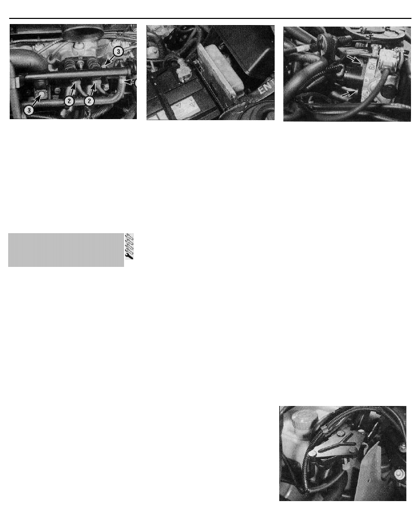
1905 cc models
7 On models with a catalytic converter
(Motronic M1.3 system), remove the ignition
HT coil as described in Chapter 5.
8 Depress the retaining clips, and disconnect
the wiring connectors from the four fuel
injectors.
9 Bearing in mind the information given in
Section 7, slacken the retaining clips, and
disconnect the fuel feed and return hoses
from the either end of the fuel rail. Where the
original crimped-type Citroen hose clips are
still fitted, cut them off and discard them; use
standard worm-drive hose clips on refitting.
10 Slacken the retaining clip(s), and
disconnect the braking system vacuum servo
unit hose, and all the relevant
vacuum/breather hoses, from the manifold
(see illustration). Where necessary, make
identification marks on the hoses, to ensure
they are correctly reconnected on refitting.
11 Slacken or cut the retaining clip (as
applicable), and disconnect the breather hose
from the top of the cylinder head cover.
12 Slacken and remove the bolt securing the
support stay to the underside of the manifold,
and the bolt securing the oil filler/breather
neck to the left-hand side of the manifold (see
illustration).
13 Undo the five manifold retaining nuts, and
withdraw the manifold from the engine
compartment. Recover the manifold gasket(s),
and discard them - new gasket(s) must be
used on refitting.
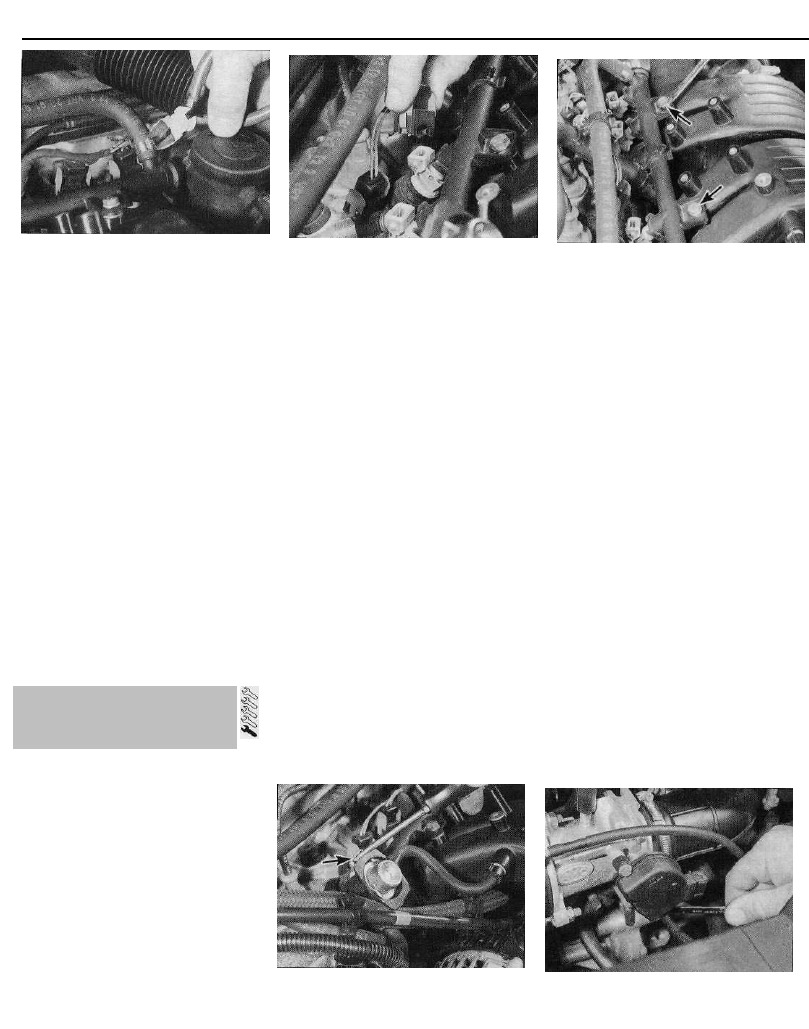
18.10 Disconnecting the braking system
vacuum servo unit hose from the manifold
-1905 cc models
18.12 On 1905 cc models, undo the bolt
(arrowed) securing the oil filler/breather
neck to the manifold
18 Inlet manifold -
removal and refitting
4C•14 Fuel and exhaust systems - multi-point fuel injection models
18.16 Removing the dipstick tube
retaining bolt - 1998 cc 8-valve models
1998 cc 8-valve models
14 Carry out the operations described above
in paragraphs 8 to 10.
15 Release the retaining clip, and free all the
disconnected hoses from the clip on the top
of the fuel rail.
16 Slacken and remove the bolt securing the
dipstick tube to the side of the manifold (see
illustration).
17 Undo the six nuts and bolts securing the
manifold to the cylinder head, and remove the
manifold from the engine compartment (see
illustration). Recover the manifold seals, and
discard them - new ones must be used on
refitting.
1998 cc 16-valve models
18 Slacken the retaining clip, and disconnect
the large breather hose from the front of the
oil filler neck.
19 Disconnect the vacuum/breather hoses
from their unions on the front of the manifold,
noting the location of each hose (see
illustration).
20 Undo the three retaining screws, and lift
off the cover from the top of the inlet
manifold-to-ACAV valve assembly joint. Free
the wiring loom, and position it clear of the
manifold (see illustration).
21 Slacken and remove the screws securing
the inlet manifold to the ACAV butterfly valve
housing, then manoeuvre the inlet manifold
out of the engine compartment. Recover the
18.17 Manifold retaining nut and bolt
locations (arrowed) -1998 cc 8-valve
models
four intake tract sealing rings from the
manifold, and discard them - new ones must
be used on refitting.
Refitting
22 Refitting is a reverse of the relevant
removal procedure, noting the following
points:
(a) On 1905 cc models, ensure that the
manifold and cylinder head mating
surfaces are clean and dry, and fit new
manifold gasket(s) over the studs. Refit
the manifold, and tighten its retaining nuts
to the specified torque.
(b) On 1761 cc and 1998 cc models, ensure
that the manifold and cylinder head
mating surfaces are clean and dry, then
locate the new seals in their recesses in
the manifold. Refit the manifold and
tighten its retaining nuts and bolts (1761
and 1998 cc 8-valve models) to the
specified torque; on 16-valve models,
tighten the retaining screws securely.
(c) Ensure that all relevant hoses are
reconnected to their original positions and
are securely held (where necessary) by
the retaining clips.
(d) Refit the throttle housing as described in
Section 12.
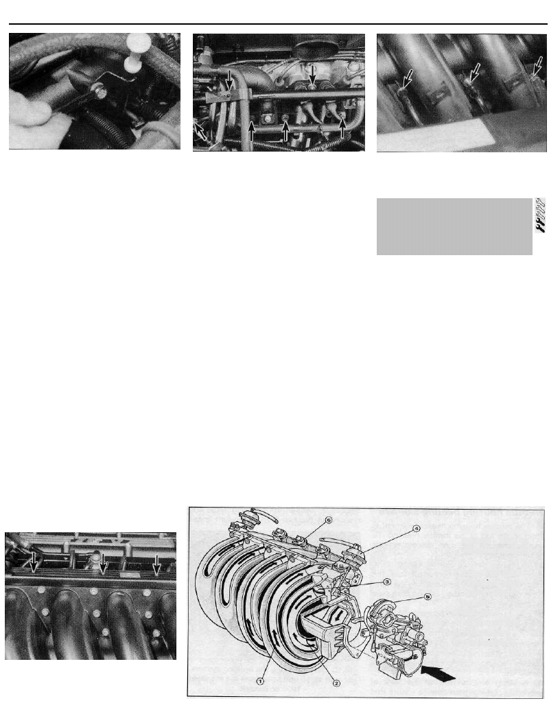
18.19 On 1998 cc 16-valve models, disconnect
the vacuum and breather hoses (arrowed)
from the front of the inlet manifold . . .
General information
1 To ensure optimum efficiency at high
engine speeds, and maximum torque at lower
engine speeds, 16-valve models have an inlet
manifold with a variable intake tract system.
Citroen call this system ACAV (variable
acoustic characteristic induction) (see
illustration).
2 The inlet manifold is divided into two tracts
of different length and diameter; a long tract
(for low-speed torque) which is 650 mm long,
diameter 36 mm, and a short tract (for high-
speed power) which is 370 mm long, diameter
45 mm.
3 Situated between the manifold and the
cylinder head is a line of four butterfly valves,
mounted in an alloy housing. Mounted on
either end of the housing is a vacuum
diaphragm assembly. Each diaphragm is
connected to the butterfly valve spindles via a
pushrod. The vacuum diaphragms are
connected to an electrically-operated
solenoid valve, which is in turn connected to
the braking system vacuum pump. The pump
18.20 . . . then undo the three retaining
screws (arrowed) and remove the cover
from the top of the manifold
19.1 ACAV intake
system -1998 cc
16-valve models
1 Long inlet tract
2 Short inlet tract
3 ACAV butterfly
valves
4 Vacuum
diaphragm unit
5 Throttle cam
6 Fuel injector
19 ACAV intake system
(1998 cc 16-valve models) -
general information, removal
and refitting
Fuel and exhaust systems - multi-point fuel injection models 4C•15
is mounted on the end of the cylinder head,
and is driven off the left-hand end of the inlet
camshaft.
4 At engine speeds below 1800 rpm and
above 5080 rpm, the ECU closes the solenoid
valve, shutting off the vacuum supply to the
diaphragms, and the butterfly valves are
closed. With the valves closed, the short
intake tracts are closed, and the incoming air
flows only through the long intake tract,
boosting the torque output.
5 At engine speeds between 1800 rpm and
5080 rpm, the ECU opens the solenoid valve.
The vacuum present in the pump is then
allowed to act on the vacuum diaphragms,
which draws the pushrods into the diaphragm
bodies, and opens up the four butterfly valves.
With the valves open, the incoming air is
allowed to flow through both the short and
long intake tracts, for maximum power.
6 To check the system, start the engine and
allow it to idle. Slowly increase the engine
speed, whilst observing the vacuum
diaphragm pushrods. At approximately 1800
rpm, the pushrods should be drawn into the
diaphragm bodies (valves open). Release the
throttle cam, and allow the engine to idle
again; the pushrods should extend from the
diaphragms (valves closed).
7 To check the operation of the solenoid
valve, disconnect the vacuum pipe from the
diaphragm. Start the engine, and allow it to
idle. Place your finger over the end of the
pipe; no vacuum should be present in the
pipe. Slowly increase the engine speed; at
approximately 1800 rpm, vacuum should be
felt in the pipe. Allow the engine to idle again,
and check that the vacuum supply is switched
off. If this is not the case, either the solenoid
valve or its supply voltage is at fault.
8 To check the operation of either vacuum
diaphragm assembly, disconnect the vacuum
pipe, and suck hard at the control valve stub; the
pushrod should be drawn into the diaphragm
body, and the valve should open. If this is not
the case, the vacuum diaphragm is faulty.
Removal and refitting
ACAV valve assembly
9 Remove the inlet manifold as described in
Section 18.
10 Bearing in mind the information given in
Section 7, slacken the retaining clip, and
disconnect the fuel feed and return hoses
from their unions on the fuel rail. Where the
original crimped-type Citroen hose clips are
still fitted, cut them off and discard them; use
standard worm-drive hose clips on refitting.
11 Depress the retaining tangs, and
disconnect the wiring connectors from the
four injectors. To avoid the possibility of the
wiring connectors being incorrectly
reconnected on refitting, mark each
connector with its relevant cylinder number
(No 1 is at the transmission end of the engine).
12 Disconnect the vacuum hoses from the
fuel pressure regulator and the ACAV
diaphragm hose T-piece.
19.16 ACAV vacuum diaphragm unit -
1998 cc 16-valve models
13 Slacken and remove the nuts and three
bolts securing the valve assembly to the
cylinder head, then slide the assembly off its
mounting studs and remove it from the engine
compartment. Remove the valve assembly
gasket from the head, and discard it - a new
one must be used on refitting.
14 Examine the assembly, checking that the
butterfly valves open freely and close
smoothly. If not, the assembly must be
renewed. The only components available
separately are the vacuum diaphragm units -
if either one is faulty, it must be renewed as
described below.
15 Refitting is a reverse of the removal
procedure, noting the following points:
(a) Ensure that the valve assembly and cylinder
head mating surfaces are clean and dry, and
fit the new manifold gasket over the studs.
Refit the valve assembly, and securely
tighten its retaining nuts and bolts.
(b) Ensure all relevant hoses are reconnected to
their original positions, and are securely held
(where necessary) by the retaining clips.
(c) Refit the inlet manifold as described in
Section 18.
(d) On completion, check the operation of the
ACAV system as described above.
Vacuum diaphragm unit
16 Disconnect the vacuum hose from the
diaphragm unit. Using a suitable flat-bladed
screwdriver, carefully lever the unit pushrod off
the valve linkage balljoint (see illustration).
17 Slacken and remove the two bolts
securing the diaphragm unit mounting bracket
to the valve assembly, and remove the
diaphragm from the engine.
18 Refitting is a reversal of the removal
19.19 ACAV solenoid valve retaining
nut (1), wiring connector (2) and hose
connections (3) -1998 cc 16-valve models
procedure, ensuring that the diaphragm
pushrod is clipped firmly onto the linkage
balljoint.
Solenoid valve
19 The solenoid control valve is mounted on
the left-hand end of the cylinder head (see
illustration). To remove the valve, first
disconnect the battery negative terminal.
20 Depress the retaining clip, and disconnect
the wiring connector from the valve.
21 Undo the nut securing the valve to the
cylinder head, then withdraw the valve,
disconnecting its vacuum hoses as they
become accessible.
22 Refitting is a reversal of the removal
procedure. Test the system on completion, as
described above.
20 Exhaust manifold -
removal and refitting
Removal
1 Firmly apply the handbrake, then jack up
the front of the vehicle and support it on axle
stands.
2 On 1905 cc models, to improve access to
the manifold from above, remove the air
cleaner housing as described in Section 2,
then undo the two mounting bracket retaining
bolts, and remove the bracket from the top of
the exhaust manifold (see illustrations).
3 On all models, undo the bolts securing the
shroud to the top of the manifold, and remove
the shroud from the manifold (see
illustration).
4 Slacken and remove the two nuts securing
the front pipe flange joint to the manifold, and
20.2a On 1905 cc models, undo the two
retaining bolts (arrowed)...
20.2b . . . and remove the air cleaner
mounting bracket from the top of exhaust
manifold
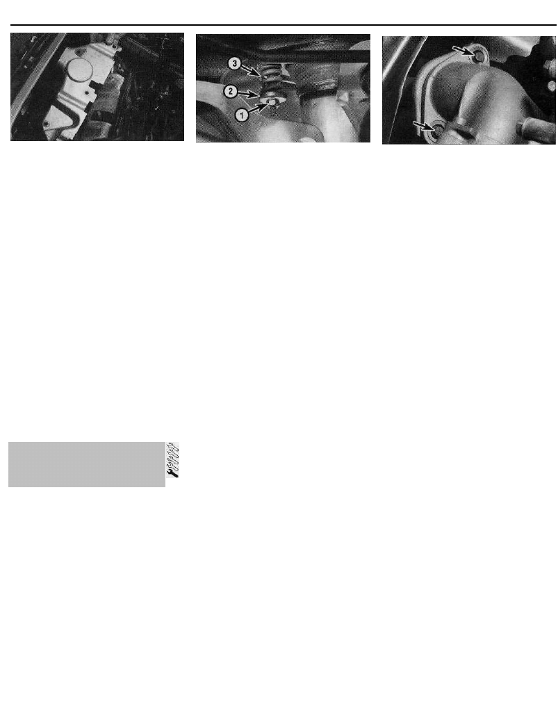
4C•16 Fuel and exhaust systems - multi-point fuel injection models
20.3 Undo the retaining bolts and remove
the exhaust manifold shroud (1905 cc
model shown)
recover the springs. Remove the bolts, then
free the front pipe from the manifold, and
recover the wire-mesh sealing ring. Either
support the front pipe, to avoid placing any
strain on the lambda sensor wiring (where
fitted), or disconnect the lambda sensor
wiring connectors.
5 Undo the retaining nuts securing the
manifold to the head. Manoeuvre the manifold
out of the engine compartment, and discard
the manifold gasket(s) - new ones should be
obtained for refitting.
Refitting
6 Refitting is the reverse of the removal
procedure, noting the following points:
(a) Examine all the exhaust manifold studs for
signs of damage and corrosion; remove
all traces of corrosion, and repair or
renew any damaged studs.
(b) Ensure that the manifold and cylinder head
sealing faces are clean and flat, and fit the
new manifold gaskets. Tighten the manifold
retaining nuts to the specified torque.
(c) Reconnect the front pipe to the manifold,
using the information given in Section 21.
General information
1 On 1905 cc models without a catalytic
converter, the exhaust system consists of two
sections: the front pipe and intermediate
silencer box, and the tailpipe and main
silencer box. The front pipe-to-manifold joint
is of the spring-loaded ball type, to allow for
movement in the exhaust system, and the
front pipe-to-silencer joint is secured by a
clamping ring.
2 On all other models, the exhaust system
consists of three sections: the front pipe and
catalytic converter, the intermediate pipe and
silencer box, and the tailpipe and main silencer
box. All exhaust sections are joined by flanged
joints. The front pipe-to-manifold joint is of the
spring-loaded ball type, to allow for movement
in the exhaust system, and the front pipe-to-
intermediate pipe and intermediate pipe-to-
silencer joints are secured by clamping rings.
3 On all models, the system is suspended
21.6a Exhaust front pipe-to-manifold joint
securing nut (1), spring cup (2) and
spring (3) - viewed from underneath
throughout its entire length by rubber mountings.
Removal
4 Each exhaust section can be removed
individually, or alternatively, the complete
system can be removed as a unit. Even if only
one part of the system needs attention, it is
often easier to remove the whole system and
separate the sections on the bench.
5 To remove the system or part of the
system, first jack up the front or rear of the
car, and support it on axle stands.
Alternatively, position the car over an
inspection pit, or on car ramps.
Front pipe -1905 cc models without a
catalytic converter
6 Slacken and remove the two nuts securing
the front pipe to the manifold, and recover the
spring cups and springs. Remove the bolts,
then release the front pipe from the manifold,
and recover the wire-mesh gasket from the
joint (see illustrations).
7 Slacken the front pipe-to-tailpipe clamping
ring bolt(s), and disengage the clamp from the
flange joint.
8 Free the front pipe from its mounting
rubbers, and withdraw it from underneath the
vehicle.
Front pipe - all models with a catalytic
converter
9 Trace the wiring back from the lambda
(oxygen) sensor to its wiring connectors, and
disconnect it from the main wiring harness.
10 Disconnect the front pipe from the manifold
and intermediate pipe as described above in
paragraphs 6 and 7, then remove the front pipe
from underneath the vehicle. Be careful not to
damage the catalytic converter - it is fragile.
Intermediate pipe - all models with a
catalytic converter
11 Slacken the intermediate pipe clamping
ring bolts, and disengage the clamps from
both the flange joints.
12 Free the intermediate pipe from its
mounting rubbers, and withdraw it from
underneath the vehicle.
Tailpipe - all models
13 Slacken the intermediate pipe-to-tailpipe
clamping ring bolt(s), and disengage the
clamp from the flange joint.
14 Unhook the tailpipe from its mounting
rubbers, and remove it from the vehicle.
21.6b Exhaust front pipe-to-manifold joint
bolts (arrowed) - viewed from above
Complete system - all models
15 Using the information given under the
relevant sub-heading above, unbolt the front
pipe from the manifold, and disconnect the
lambda sensor wiring (where applicable). Free
the system from all its mounting rubbers, and
withdraw it from under the vehicle.
Heat shield(s) - all models
16 The heat shields are secured to the
underside of the body by various nuts and
bolts. Each shield can be removed once the
relevant exhaust section has been removed. If
the shield is being removed to gain access to a
component located behind it, it may prove
sufficient in some cases to remove the retaining
nuts and/or bolts, and simply lower the shield,
without disturbing the exhaust system.
Refitting
17 Each section is refitted by a reverse of the
removal sequence, noting the following points:
(a) Clamping rings which are secured by a
single bolt (fitted to all 1998 cc models,
and to some others) should be renewed
as a matter of course. They are designed
to deform on tightening, and cannot be
re-used.
(b) Ensure that all traces of corrosion have
been removed from the flanges, and
renew all necessary gaskets.
(c) Inspect the rubber mountings for signs of
damage or deterioration, and renew as
necessary.
(d) Prior to assembling the spring-loaded ball
type joint, a smear of high-temperature
grease should be applied to the joint
mating surfaces. Citroen recommend the
use of Gripcott AF G2 grease (available
from your Citroen dealer).
(e) On joints which are secured by clamping
rings, apply a smear of exhaust system
jointing paste to the joint mating surfaces,
to ensure an gas-tight seal.
(f) Prior to tightening the exhaust system
fasteners, ensure all rubber mountings are
correctly located, and that there is
adequate clearance between the exhaust
system and vehicle underbody.
(g) On models with clamping rings which are
secured by two bolts, tighten the
clamping ring nuts evenly and
progressively to the specified torque, to
ensure that the clearance between the
clamp halves is equal on either side.
21 Exhaust system -
general information, removal
and refitting
Wyszukiwarka
Podobne podstrony:
zx 01
1570 04C
zx 00
zx 04d
zx 08
04c RACHUNEK ZYSKÓW I STRAT
FIG 04C
zx 10
FIG-04C
04c krzyw niez
zx 07a
zx 02a
PREZENTACJA FIRMY „X
IT CCTV 04C
zx 07b
zx ref
04C Wyścig szczurów 09-10-2010, KSW Kędzierzyn spotkania, Spotkania i sprawozadnia K-K KSW
ZX olej w wodzie
więcej podobnych podstron