7A•1
Chapter 7 Part A: Manual transmission
Contents
Gearchange linkage - general information and adjustment 2
Gearchange linkage - removal and refitting 3
General information 1
Manual transmission - removal and refitting 7
Manual transmission oil level check See Chapter 1
Degrees of difficulty
Manual transmission oil renewal See Chapter 1
Manual transmission overhaul - general information 8
Oil seals - renewal 4
Reversing light switch - testing, removal and refitting 5
Speedometer drive - removal and refitting 6
Specifications
General
Type Manual, five forward speeds and reverse. Synchromesh on all
forward speeds
Designation:
1124 cc and 1360 cc models MA
1580 cc and larger-engined models BE3
Transmission code:
H1A (1124 cc) and KDY (1360 cc) engines CB 04 or CB 60
HDZ (11 24 cc) engine CB 06 or CB 62
K2D (1360 cc) engine CB 05 or CB 61
KDX (1360 cc) engine CB 60
B4A and BDY (1580 cc) engines CJ 84
D6E and DKZ (1905 cc) engines CJ 85
LFZ (1761 cc) engine CL 34 or CJ 84
RFX (1998 cc 8-valve) engine CL 35 or CJ 85
RFY (1998 cc 16-valve) engine CL 46
Note: Refer to Chapter 2 for further information on engine code identification
Ratios (typical)
Transmission code CB:
1st 3.417 : 1
2nd 1.810 : 1
3rd 1.276 : 1
4th 0.975 : 1
5th 0.767 : 1
Reverse 3.583 : 1
Final drive 4.286 : 1
Transmission codes CJ and CL:
1st 3.455 : 1
2nd 1.850 : 1
3rd 1.360 : 1
4th 1.069 : 1
5th 0.865 : 1
Reverse 3.333 : 1
Final drive 3.750 : 1
Lubrication
Recommended oil Total transmission BV 75/80W
Capacity 2.0 litres
Recommended gearchange linkage grease Esso Norva 275 or Total Multis G6
Easy, suitable for
novice with little
experience
Fairly easy, suitable
for beginner with
some experience
Fairly difficult, suitable
for competent DIY
mechanic
Difficult, suitable for
experienced DIY
mechanic
Very difficult,
suitable for expert DIY
or professional
7A•2 Manual transmission
Torque wrench settings Nm lbf ft
MA transmission - 1124 cc and 1360 cc models
Gearchange selector rod pivot bolts 17 13
Selector lever mounting bracket nuts 17 13
Oil filler/level plug 25 18
Oil drain plug 25 18
Clutch release bearing guide
sleeve bolts 12 9
Reversing light switch 25 18
Left-hand engine/transmission mounting:
Mounting bracket-to-transmission nuts 18 13
Mounting bracket-to-body bolts 25 18
Centre nut 38 28
Engine-to-transmission unit fixing bolts 35 26
Roadwheel bolts 90 66
BE3 transmission -1580 cc and larger-engined models
Gearchange linkage bellcrank pivot bolt 28 21
Oil filler/level plug 22 16
Oil drain plug 35 26
Clutch release bearing guide sleeve bolts 12 9
Reversing light switch 25 18
Left-hand engine/transmission mounting:
Mounting bracket-to-body bolts 25 18
Mounting stud 50 36
Centre nut 80 59
Engine-to-transmission unit fixing bolts 50 37
Clutch cable bracket retaining bolts ("pull-type" clutch only) 18 13
Roadwheel bolts 90 66
1 General information
1 The transmission is contained in a cast-
aluminium alloy casing bolted to the engine's
left-hand end, and consists of the gearbox
and final drive differential - often called a
transaxle.
2 Drive is transmitted from the crankshaft via
the clutch to the input shaft, which has a
splined extension to accept the clutch friction
plate, and rotates in sealed ball-bearings.
From the input shaft, drive is transmitted to
the output shaft, which rotates in a roller
bearing at its right-hand end, and a sealed
ball-bearing at its left-hand end. From the
output shaft, the drive is transmitted to the
differential crownwheel, which rotates with
the differential case and planetary gears, thus
driving the sun gears and driveshafts. The
rotation of the planetary gears on their shaft
allows the inner roadwheel to rotate at a
slower speed than the outer roadwheel when
the car is cornering.
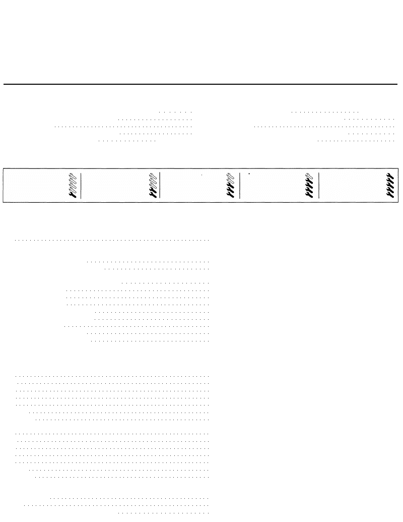
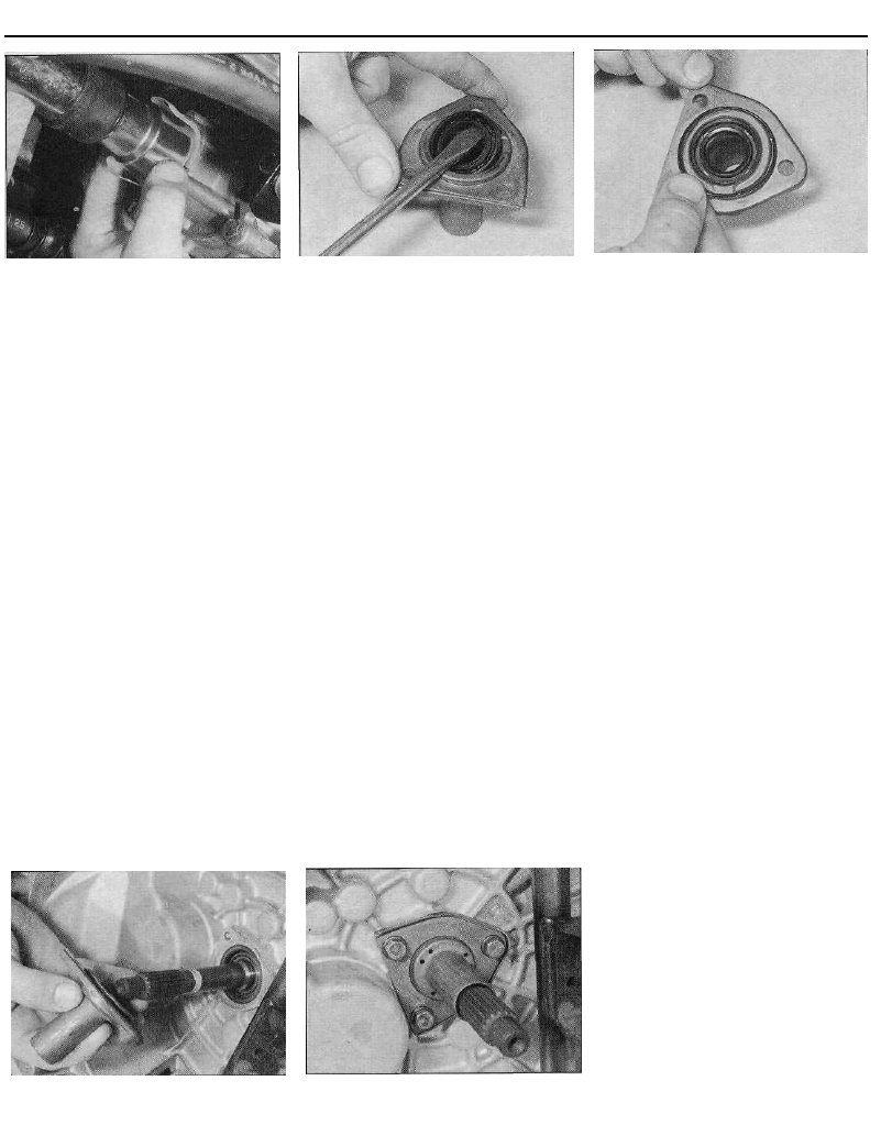
3 The input and output shafts are arranged
side by side, parallel to the crankshaft and
driveshafts, so that their gear pinion teeth are
in constant mesh. In the neutral position, the
output shaft gear pinions rotate freely, so that
drive cannot be transmitted to the
crownwheel (see illustration).
4 Gear selection is via a floor-mounted lever
and selector rod mechanism. The selector rod
causes the appropriate selector fork to move
its respective synchro-sleeve along the shaft,
to lock the gear pinion to the synchro-hub.
Since the synchro-hubs are splined to the
output shaft, this locks the pinion to the shaft,
so that drive can be transmitted. To ensure
that gear-changing can be made quickly and
quietly, a synchro-mesh system is fitted to all
forward gears, consisting of baulk rings and
spring-loaded fingers, as well as the gear
pinions and synchro-hubs. The synchro-mesh
cones are formed on the mating faces of the
baulk rings and gear pinions.
5 Two different manual transmission units
are used on the models covered in this
manual; 1124 cc and 1360 cc models have
the "MA" transmission, whereas 1580 cc and
larger-engined models are fitted with the
"BE3" unit.
1.1 Cutaway view of the BE3 manual transmission
Manual transmission 7A•3
2 Gearchange linkage - general
information and adjustment
1 If a stiff, sloppy or imprecise gearchange
leads you to suspect that a fault exists within
the linkage, first dismantle it completely, and
check it for wear or damage as described in
Section 3. Reassemble it, applying a smear of
the special grease to all bearing surfaces.
2 If this does not cure the fault, the car should
be examined by an expert, as the fault must
lie within the transmission itself. There is no
adjustment as such in the linkage.
3 On 1580 cc and larger-engined models,
note that, while the length of the link rods can
be altered as described below, this is for initial
setting-up only, and is not intended to provide
a form of compensation for wear. If the link
rods have been renewed, or if the length of
the originals is incorrect, adjust them as
follows.
Link rod adjustment - 1580 cc and
larger-engined models
4 Firmly apply the handbrake, then jack up
the front of the vehicle and support it on axle
stands. Access to the link rods is poor, but
they can be reached both from above and
below the vehicle.
5 Working in (or under) the engine
compartment, measure the length of each link
rod, and compare this to the length specified
(see illustration). Note the measurements
given are the distances between the centre
points of the link rod balljoints, and not the
total length of the rod.
6 If adjustment is necessary, slacken the
locknut, then carefully lever the relevant link
rod off its balljoint on the transmission unit.
Turn the end of the rod until the specified
distance between the link rod balljoint centres
is obtained, then press the disconnected end
of the rod firmly back onto its balljoint and
securely tighten the link rod locknut.
7 Once all link rod lengths are correctly set,
check that all gears can be selected, and that
the gearchange lever returns properly to its
correct at-rest (neutral) position.
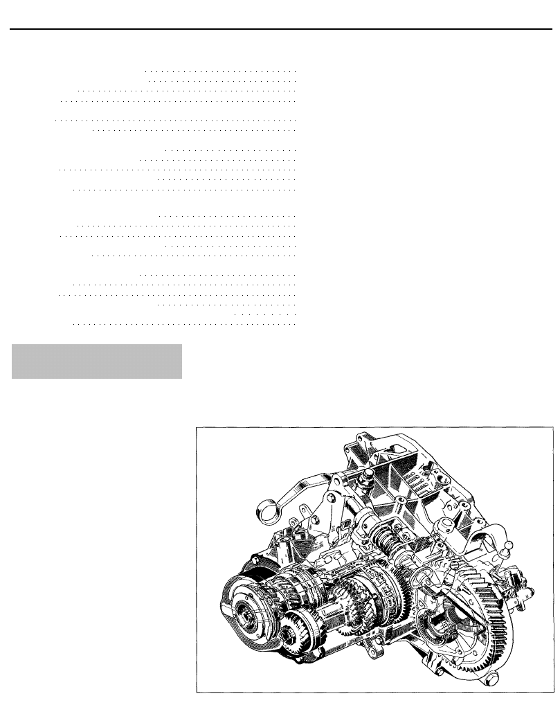
3.2 Transmission selector lever
arrangement - 1124 cc and 1360 cc
models. Selector rod pivot bolt (arrowed)
housing, then remove the bracket and lever
assembly from the transmission.
4 Inspect all the linkage components for
signs of wear or damage, paying particular
attention to the selector lever balljoint, and
renew worn components as necessary. If
necessary, remove the gearchange lever as
follows.
5 Where a leather gaiter is fitted to the lever,
carefully prise the gearchange lever trim panel
out from the centre console, then release the
pop fastener and velcro strip, and remove the
gaiter. Where a rubber gaiter is fitted, pull the
knob from the gearchange lever. Prise the
gearchange lever trim panel out from the
centre console and remove the gaiter;
alternatively, undo the two retaining screws
securing the small centre console to the floor,
and remove the gaiter and console assembly
from the vehicle (as applicable). Undo the four
retaining nuts, then lower the gearchange
lever out of position and remove it from
underneath the vehicle (see illustrations).
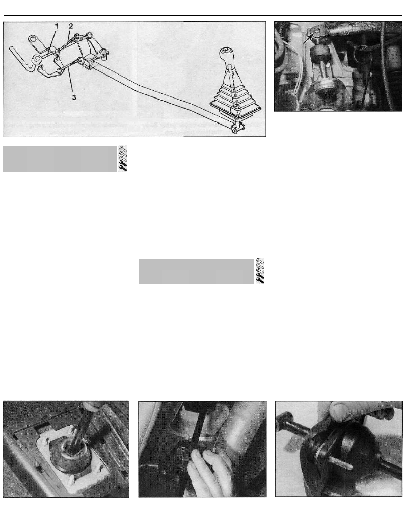
6 Peel back the lower gaiter from the base of
the gearchange lever, then disengage the
lever mounting plate, and slide the upper
gaiter up the lever to gain access to the
gearchange lever pivot ball. Examine the lever
components for signs of wear or damage,
paying particular attention to the rubber
gaiters, and renew components as necessary.
The lever can be separated from its baseplate
after the retaining ring has been undipped
(see illustrations).
3.5a Slacken and remove the four
retaining nuts . . .
3.5b . . . then remove the gearchange lever
from underneath the vehicle
3.6a Peel back the lower gaiter . . .
2.5 Gearchange linkage link rod specified lengths
1 260.5 ± 1 mm 2 106 ± 1 mm 3 106.5 ± 1 mm
3 Gearchange linkage -
removal and refitting
Removal
1 Firmly apply the handbrake, then jack up
the front of the vehicle and support it on axle
stands.
1124 cc and 1360 cc models
2 Slacken and remove the nut and washer,
then withdraw the pivot bolt from each end of
the selector rod. Disengage the rod from
gearchange lever and selector lever, and
remove it from underneath the vehicle (see
illustration).
3 Undo the two nuts securing the selector
lever mounting bracket to the transmission
7A•4 Manual transmission
3.6b . . . then disengage the mounting
p l a t e . . .
1580 cc and larger-engined models
7 Slacken and remove the nut, and withdraw
the pivot bolt securing the selector rod to the
base of the gearchange lever.
8 Using a flat-bladed screwdriver, carefully
lever the three link rods off their balljoints on
the transmission (see illustration). Disengage
the selector rod from the bellcrank pivot, and
remove it from underneath the vehicle.
9 Undo the two retaining screws, and unclip
the heat shield from the top of the steering
gear assembly.
10 Carefully prise the plastic cap off the bolt
securing the gearchange linkage bellcrank to
the subframe.
11 Slacken and remove the bellcrank pivot
bolt and washer, then manoeuvre the
bellcrank and link rod out from under the
vehicle, and recover the spacer and pivot
bushes from the centre of the bellcrank.
12 Inspect all the linkage components for
signs of wear or damage, paying particular
attention to the pivot bushes and link rod
balljoints, and renew worn components as
necessary. If necessary, the gearchange lever
can be removed and inspected as described
above in paragraphs 5 and 6.
Refitting
1124 cc and 1360 cc models
13 Refitting is a reversal of the removal
procedure, noting the following points:
(a) Before refitting, apply a smear of the
3.8 On 1580 cc and larger-engined
models, disconnect the three gearchange
linkage link rods (arrowed) from their
transmission balljoints
3.6c . . . and peel the upper gaiter away
from the lever baseplate
special grease (see Specifications) to the
selector lever and rod pivots.
(b) Ensure the gearchange lever rubber
gaiters are correctly seated before
refitting the lever assembly to the vehicle.
(c) Tighten the selector rod pivot bolts and
the selector lever bracket nuts to the
specified torque.
1580 cc and larger-engined models
14 Refitting is a reversal of the removal
procedure, noting the following points:
(a) Before refitting, check and if necessary
adjust the link rod lengths as described in
Section 2.
(b) Apply a smear of the special grease (see
Specifications) to the gearchange lever
pivot ball, the link rod balljoints and the
bellcrank ball and pivot bushes.
(c) Ensure the gearchange lever rubber
gaiters are correctly seated before
refitting the lever assembly to the vehicle.
(d) Tighten the bellcrank pivot bolt to the
specified torque, and ensure the link rods
are securely pressed onto their balljoints.
4 Oil seals - renewal
Driveshaft oil seals
1 Chock the rear wheels, apply the
handbrake, then jack up the front of the car
3.6d The lever and baseplate can be
separated once the retaining ring has been
undipped
and support it on axle stands. Remove the
appropriate front roadwheel.
2 Drain the transmission oil as described in
Chapter 1.
3 Slacken and remove the three nuts
securing the balljoint to the lower suspension
arm, then withdraw the bolts and free the
balljoint from the arm. Discard the nuts - new
ones must be used on refitting.
Right-hand seal
4 Loosen the two intermediate bearing
retaining bolt nuts, then rotate the bolts
through 90° so that their offset heads are clear
of the bearing outer race.
5 Carefully pull the swivel hub assembly
outwards, and pull on the inner end of the
driveshaft to free the intermediate bearing
from its mounting bracket.
6 Once the driveshaft end is free from the
transmission, slide the dust seal off the inner
end of the shaft, noting which way around it is
fitted, and support the inner end of the
driveshaft to avoid damaging the constant
velocity joints or gaiters.
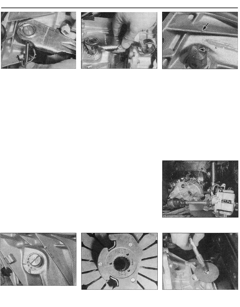
7 Carefully prise the oil seal out of the
transmission, using a large flat-bladed
screwdriver (see illustration).
8 Remove all traces of dirt from the area
around the oil seal aperture, then apply a
smear of grease to the outer lip of the new oil
seal. Fit the new seal into its aperture, and
drive it squarely into position using a suitable
tubular drift (such as a socket) which bears
only on the hard outer edge of the seal, until it
4.7 Use a large flat-bladed screwdriver to
prise the driveshaft oil seals out of position
4.8a Fit the new seal to the transmission,
noting the plastic seal protector . . .
Manual transmission 7A•5
4.8b . . . and tap it into position using a
tubular drift
abuts its locating shoulder. If the seal was
supplied with a plastic protector sleeve, leave
this in position until the driveshaft has been
refitted (see illustrations).
9 Thoroughly clean the driveshaft splines,
then apply a thin film of grease to the oil seal
lips and to the driveshaft inner end splines.
10 Slide the dust seal into position on the
end of the shaft, ensuring that its flat surface
is facing the transmission.
11 Carefully locate the inner driveshaft
splines with those of the differential sun gear,
taking care not to damage the oil seal, then
align the intermediate bearing with its
mounting bracket, and push the driveshaft
fully into position. If necessary, use a soft-
faced mallet to tap the outer race of the
bearing into position in the mounting bracket.
12 Ensure the intermediate bearing is
correctly seated, then rotate its retaining bolts
back through 90° so that their offset heads
are resting against the bearing outer race, and
tighten the retaining nuts to the specified
torque. Remove the plastic seal protector
(where supplied), and slide the dust seal tight
up against the oil seal.
13 Align the balljoint with the lower arm, and
fit the three retaining bolts. Fit new retaining
nuts to the bolts, and tighten them to the
specified torque setting.
14 Refit the roadwheel, then lower the
vehicle to the ground and tighten the
roadwheel bolts to the specified torque.
15 Refill the transmission with the specified
4.22 Removing the input shaft seal from
the guide sleeve
type and amount of fluid/oil, and check the
level using the information given in Chapter 1.
Left-hand seal
16 Pull the swivel hub assembly outwards
and withdraw the driveshaft inner constant
velocity joint from the transmission, taking
care not to damage the driveshaft oil seal.
Support the driveshaft, to avoid damaging the
constant velocity joints or gaiters.
17 Renew the oil seal as described above in
paragraphs 7 to 9.
18 Carefully locate the inner constant
velocity joint splines with those of the
differential sun gear, taking care not to
damage the oil seal, and push the driveshaft
fully into position. Where fitted, remove the
plastic protector from the oil seal.
19 Carry out the operations described above
in paragraphs 13 to 15.
Input shaft oil seal
20 Remove the transmission as described in
Section 7.
21 Undo the three bolts securing the clutch
release bearing guide sleeve in position, and
slide the guide off the input shaft, along with
its O-ring or gasket (as applicable). Recover
any shims or thrustwashers which have stuck
to the rear of the guide sleeve, and refit them
to the input shaft.
22 Carefully lever the oil seal out of the guide
using a suitable flat-bladed screwdriver (see
illustration).
23 Before fitting a new seal, check the input
4.25b . . . refit the guide sleeve over the
input s h a f t . . .
4.25c . . . and secure it in position with its
three retaining bolts
4.25a Fit a new O-ring/gasket (as
applicable)...
shaft's seal rubbing surface for signs of burrs,
scratches or other damage, which may have
caused the seal to fail in the first place. It may
be possible to polish away minor faults of this
sort using fine abrasive paper; however, more
serious defects will require the renewal of the
input shaft. Ensure that the input shaft is clean
and greased, to protect the seal lips on
refitting.
24 Dip the new seal in clean oil, and fit it to
the guide sleeve.
25 Fit a new O-ring or gasket (as applicable)
to the rear of the guide sleeve, then carefully
slide the sleeve into position over the input
shaft. Refit the retaining bolts and tighten
them to the specified torque setting (see
illustrations).
26 Take the opportunity to inspect the clutch
components if not already done (Chapter 6).
Finally, refit the transmission as described in
Section 7.
Selector shaft oil seal
1124 cc and 1360 cc models
27 On 1124 cc and 1360 cc models, to renew
the selector shaft seal, the transmission must
be dismantled. This task should therefore be
entrusted to a Citroen dealer or transmission
specialist.
1580 cc and larger-engined models
28 Park the car on level ground, apply the
handbrake, then jack up the front of the
vehicle and support it on axle stands. Remove
the left-hand front roadwheel, and unclip the
access cover from the centre of the wheel
arch liner.
29 Using a large flat-bladed screwdriver,
lever the link rod balljoint off the transmission
selector shaft, and disconnect the link rod.
30 Carefully prise the selector shaft seal out
of the housing, and slide it off the end of the
shaft (see illustrations).
31 Before fitting a new seal, check the
selector shaft's seal rubbing surface for signs
of burrs, scratches or other damage, which
may have caused the seal to fail in the first
place. It may be possible to polish away minor
faults of this sort using fine abrasive paper;
however, more serious defects will require the
renewal of the selector shaft.
7A•6 Manual transmission
4.30a On 1580 cc and larger-engined
models, use a large flat-bladed
screwdriver to prise the selector shaft seal
out of position . . .
32 Apply a smear of grease to the new seal's
outer edge and sealing lip, then carefully slide
the seal along the selector rod. Press the seal
fully into position in the transmission housing.
33 Reconnect the link rod to the selector
shaft, ensuring that its balljoint is pressed
firmly onto the shaft. Lower the car to the
ground.
Testing
1 The reversing light circuit is controlled by a
plunger-type switch that is screwed into the
top of the transmission casing. If a fault
develops in the circuit, first ensure that the
circuit fuse has not blown.
2 To test the switch, disconnect the wiring
connector, and use a multimeter (set to the
resistance function) or a battery-and-bulb test
circuit to check that there is continuity
between the switch terminals only when
reverse gear is selected. If this is not the case,
and there are no obvious breaks or other
damage to the wires, the switch is faulty, and
must be renewed.
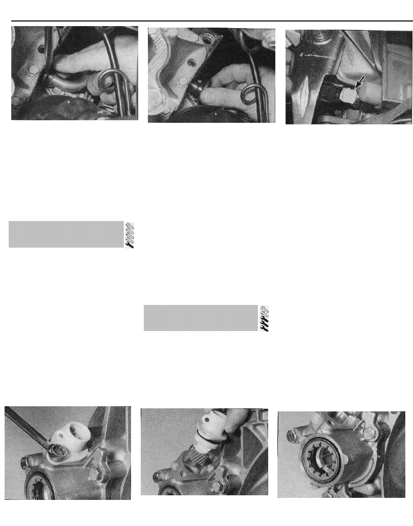
Removal
3 On some 1580 cc and larger-engined
models, to improve access to the switch, it
6.3a Slacken and remove the retaining
4.30b . . . then slide the seal off the shaft
may be necessary to remove the air intake
duct(s) as described in the relevant Part of
Chapter 4. It may also be necessary to
remove the metal plate from the top of the
transmission; the plate is retained by one of
the transmission to engine unit bolts, and by a
second bolt securing the plate to the top of
the transmission housing.
4 Disconnect the wiring connector, then
unscrew it from the transmission casing along
with its sealing washer (see illustration).
Refitting
5 Fit a new sealing washer to the switch, then
screw it back into position in the top of the
transmission housing and tighten it to the
specified torque setting. Reconnect the wiring
connector, and test the operation of the
circuit. Refit any components removed for
access.
Removal
1 Chock the rear wheels, firmly apply the
handbrake, then jack up the front of the car
and support it on axle stands. The
speedometer drive is situated on the rear of
the transmission housing, next to the inner
end of the right-hand driveshaft.
2 Pull out the speedometer cable retaining
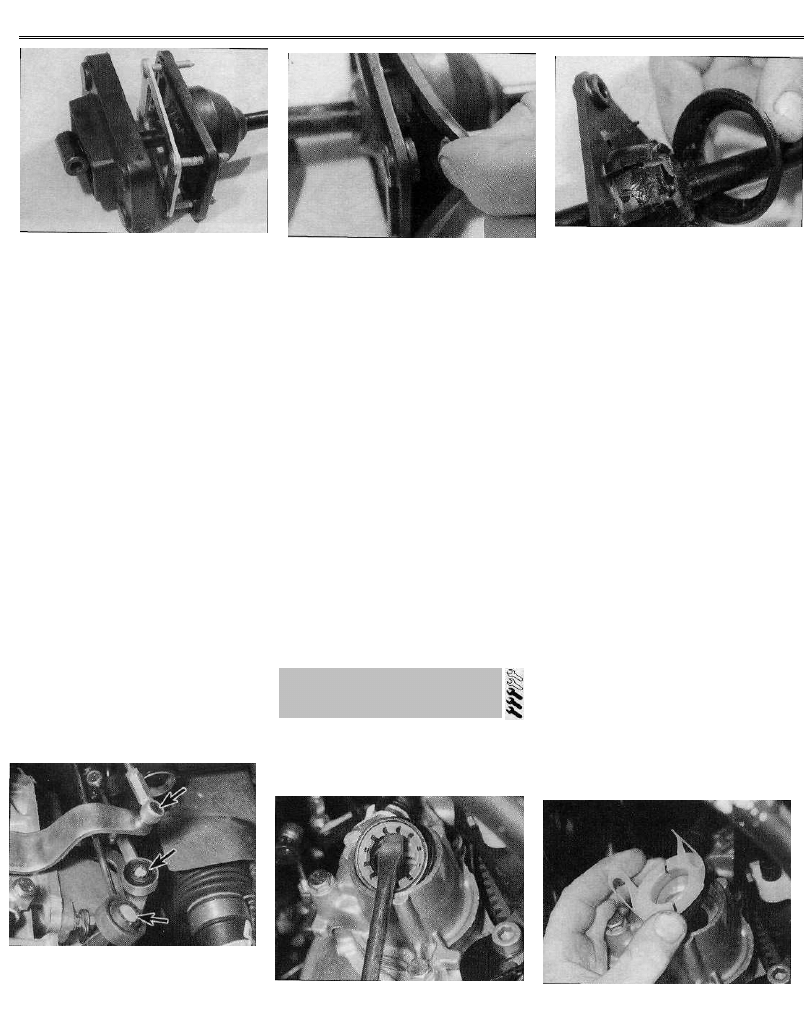
6.3b . . . then withdraw the speedometer
drive from the transmission (transmission
removed for clarity - type BE3 shown)
5.4 Disconnecting the wiring connector
from the reversing light switch (arrowed)
pin, and disconnect the cable from the
speedometer drive. Where necessary,
disconnect the wiring connector from the
speedometer drive.
3 Slacken and remove the retaining bolt,
along with the heat shield (where fitted), and
withdraw the speedometer drive and driven
pinion assembly from the transmission
housing, along with its O-ring (see
illustrations).
4 If necessary, the pinion can be slid out of
the housing, and the oil seal can be removed
from the top of the housing. Examine the
pinion for signs of damage, and renew if
necessary. Renew the housing O-ring as a
matter of course.
5 If the driven pinion is worn or damaged,
also examine the drive pinion in the
transmission housing for similar signs.
6 On 1124 cc and 1360 cc models, to renew
the drive pinion, the transmission unit must be
dismantled and the differential gear removed.
This task should therefore be entrusted to a
Citroen dealer or a transmission specialist.
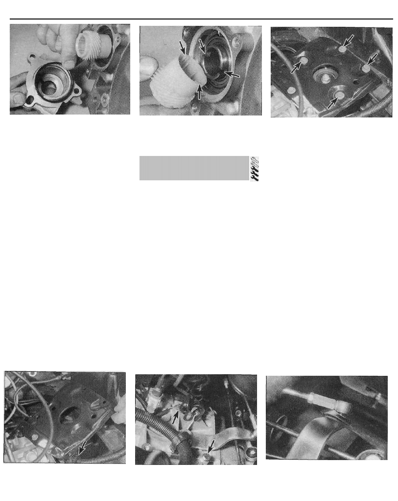
7 On 1580 cc and larger-engined models, to
remove the drive pinion, first disengage the
right-hand driveshaft from the transmission,
as described in paragraphs 1 to 7 of Section
4. Undo the three retaining bolts, and remove
the speedometer drive housing from the
transmission, along with its O-ring. Remove
the drive pinion from the differential gear, and
recover any adjustment shims from the gear
(see illustrations).
6.7a On 1580 cc and larger-engined
models (BE3 transmission), undo the three
retaining bolts . . .
5 Reversing light switch -
testing, removal and refitting
6 Speedometer drive -
removal and refitting
Manual transmission 7A•7
6.7b . . . and remove the housing, O-ring
and drive pinion from the transmission
(shown with transmission removed for
clarity)
Refitting
8 On 1580 cc and larger-engined models,
where the drive pinion has been removed, refit
the adjustment shims to the differential gear,
then locate the speedometer drive on the
gear, ensuring it is correctly engaged in the
gear slots {see illustration). Fit a new O-ring
to the rear of the speedometer drive housing,
then refit the housing to the transmission and
securely tighten its retaining bolts. Inspect the
driveshaft oil seal for signs of wear, and renew
if necessary. Refit the driveshaft to the
transmission, using the information given in
Section 4.
9 On all models, apply a smear of grease to
the lips of the seal and to the driven pinion
shaft, and slide the pinion into position in the
speedometer drive.
10 Fit a new O-ring to the speedometer drive
and refit it to the transmission, ensuring that
the drive and driven pinions are correctly
engaged.
11 Refit the retaining bolt and the heat shield
(where fitted), and tighten the bolt. Where
necessary, reconnect the wiring connector to
the speedometer drive.
12 Apply a smear of oil to the speedometer
cable O-rings, then reconnect the cable to the
drive, and secure it in position with the rubber
retaining pin. Lower the vehicle to the ground.
7.3b . . . and remove the battery support
tray. Note the wiring retaining clip
(arrowed)
Removal
1 Chock the rear wheels, then firmly apply the
handbrake. Jack up the front of the vehicle,
and securely support it on axle stands.
Remove both front roadwheels.
2 Drain the transmission oil as described in
Chapter 1, then refit the drain and filler plugs,
and tighten them to their specified torque
settings.
3 Remove the battery and battery tray as
described in Chapter 5. Slacken and remove
the battery support tray retaining bolts, then
free the wiring from its retaining clips on the
edge of the tray, and remove the tray (see
illustrations).
4 Where necessary, to improve access to the
top of the transmission unit remove the air
cleaner housing and/or intake duct (as
applicable) as described in Chapter 4.
5 Remove the starter motor as described in
Chapter 5.
6 Fully slacken the clutch cable locknut and
adjuster nut, then free the inner and outer
cable end fittings from the mounting bracket
and release lever. Release the cable from any
relevant retaining clips, and position it clear of
the transmission.
7 Disconnect the wiring connector from the
reversing light switch and, where necessary,
the speedometer drive housing. Undo the
retaining bolts, and disconnect the earth
straps from the top of the transmission
housing (see illustration). Free the wiring
from any relevant retaining clips, and position
it clear of the transmission unit.
8 On 1124 cc and 1360 cc models, slacken
and remove the nut and washer, then
withdraw the pivot bolt and disconnect the
selector rod from the transmission lever.
Where necessary, undo the bolt securing the
exhaust front pipe to its transmission
mounting bracket.
9 On 1580 cc and larger-engined models,
using a flat-bladed screwdriver, carefully lever
the three gearchange mechanism link rods off
their respective balljoints on the transmission
(see illustration). Position the rods clear of
the transmission unit.
10 On models with power steering, undo the
nuts securing the power steering pipe to the
underside of the transmission, and free the
pipe from its retaining studs (see
illustrations).
11 On 1580 cc and larger-engined models,
7.7 Slacken and remove the bolts
(arrowed) and disconnect the earth straps
from the transmission - BE3 transmission
shown
7.9 On 1580 cc and larger-engined models
(BE3 transmission), carefully lever the
gearchange link rods off their transmission
balljoints using a large flat-bladed
screwdriver
6.8 On refitting, ensure the drive pinion
dogs are correctly engaged with the gear
slots (arrowed)
7.3a Undo the four retaining bolts . . .
7 Manual transmission -
removal and refitting
7A•8 Manual transmission
7.10a On models with power steering,
undo the retaining nuts . . .
undo the retaining bolts, and remove the
flywheel lower cover plate (where fitted) from
the transmission (see illustration).
12 Withdraw the rubber retaining pin,
disconnect the speedometer cable from the
drive housing, and free it from any relevant
retaining clips (see illustrations).
13 Slacken and remove the three nuts
securing the balljoint to the left-hand lower
suspension arm, then withdraw the bolts and
free the balljoint from the arm. Discard the
nuts - new ones must be used on refitting.
Repeat the procedure on the right-hand side.
14 Release the inner end of the right-hand
driveshaft from the transmission, as described
in paragraphs 4 to 6 of Section 4.
7.10b . . . and free the power steering pipe
from its mountings on the underside of the
transmission
15 To release the left-hand driveshaft inner
constant velocity joint from the transmission,
pull the swivel hub assembly outwards and
withdraw the joint from transmission, taking
great care not to damage the driveshaft oil
seal. Support the driveshaft, to avoid
damaging the constant velocity joints or
gaiters.
16 Place a jack with a block of wood beneath
the engine, to take the weight of the engine.
Alternatively, attach a couple of lifting eyes to
the engine, and fit a hoist or support bar to
take the engine weight.
17 Place a jack and block of wood beneath
the transmission, and raise the jack to take
the weight of the transmission.
7.11 On 1580 cc and larger-engined
models, remove the flywheel lower cover
plate
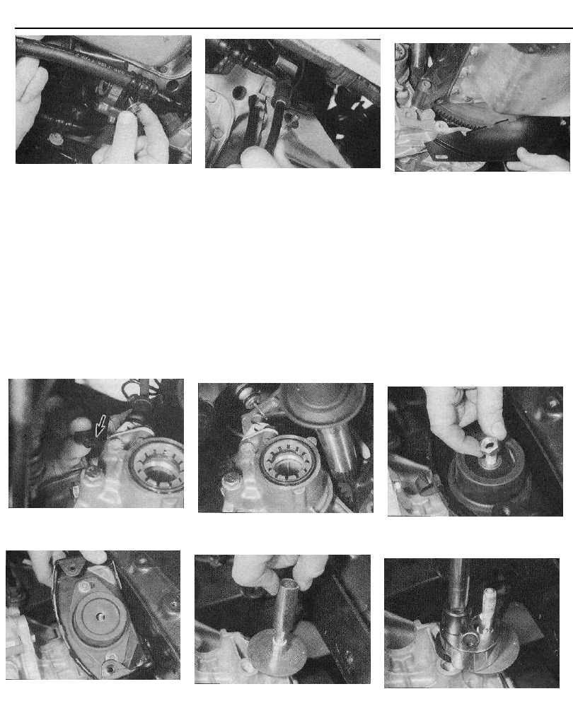
18 Slacken and remove the centre nut and
washer from the left-hand engine/
transmission mounting. Undo the two bolts
securing the mounting bracket assembly to
the vehicle body, and remove the mounting
bracket assembly (see illustrations).
19 On 1124 cc and 1360 cc models, undo the
three retaining nuts and remove the mounting
plate from the top of the transmission.
20 On 1580 cc and larger-engined models,
slide the spacer off the mounting stud, then
unscrew the stud from the top of the
transmission housing and remove it along
with its washer. If the mounting stud is tight, a
universal stud extractor can be used to
unscrew it (see illustrations).
7.12a Withdraw the rubber retaining pin
(arrowed)...
7.12b . . . and disconnect the speedometer
cable from the transmission -
BE3 transmission shown
7.18a Remove the centre nut and washer
from the left-hand mounting . . .
7.18b . . . then undo the two retaining bolts
and remove the mounting bracket
assembly
7.20a On 1580 cc and larger-engined
models, slide the spacer off the mounting
stud . . .
7.20b . . . and unscrew the mounting stud.
If the stud is tight, use a universal stud
extractor to unscrew it
Manual transmission 7A•9
7.21a On models with a "pull-type" clutch,
withdraw the retaining pin . . .
21 On models with a "pull-type" clutch
release mechanism (see Chapter 6), tap out
the retaining pin or unscrew the retaining bolt
(as applicable) and remove the clutch release
lever from the top of the release fork shaft.
This is necessary to allow the fork shaft to
rotate freely, to disengage from the release
bearing as the transmission is pulled away
from the engine. Make an alignment mark
across the centre of the clutch release fork
shaft using a scriber, paint or similar, and
mark its position relative to the transmission
housing (see illustrations). Undo the
retaining bolts, and remove the clutch cable
bracket from the top of the transmission
housing.
22 With the jack positioned beneath the
transmission taking the weight, slacken and
remove the remaining bolts securing the
transmission housing to the engine. Note the
correct fitted positions of each bolt, and the
necessary brackets, as they are removed, to
use as a reference on refitting. Make a final
check that all components have been
disconnected, and are positioned clear of the
transmission so that they will not hinder the
removal procedure.
23 With the bolts removed, move the trolley
jack and transmission to the left, to free it from
its locating dowels.
24 Once the transmission is free, lower the
jack and manoeuvre the unit out from under
7.21 b . . . then remove the clutch release
l e v e r . . .
the car (see illustration). Remove the locating
dowels from the transmission or engine if they
are loose, and keep them in a safe place.
25 On models with a "pull-type" clutch, make
a second alignment mark on the transmission
housing, marking the relative position of the
release fork mark after removal, noting the
angle at which the release fork is positioned
(see illustration 7.26a). This mark can then
be used to position the release fork before
refitting, to ensure that the fork correctly
engages with the clutch release bearing as the
transmission is installed.
Refitting
26 The transmission is refitted by a reversal
of the removal procedure, bearing in mind the
following points:
(a) Apply a little high-melting-point grease to
the splines of the transmission input shaft.
Do not apply too much, otherwise there is
a possibility of the grease contaminating
the clutch friction plate.
(b) Ensure the locating dowels are correctly
positioned prior to installation.
(c) On models with a "pull-type" clutch,
before refitting, position the clutch release
bearing so that its HAUT mark is at the
top, and the BAS mark is at the bottom,
and align the release fork shaft mark with
the second mark made on the
transmission housing (see illustrations).
7.21c . . . and make an alignment mark
between the release fork shaft and
transmission housing (arrowed)
This will ensure that the release fork and
bearing will engage correctly as the
transmission is refitted to the engine. If
the bearing and fork are correctly
engaged, the mark on the shaft should be
aligned with the original mark made on
the transmission housing. Ensure the
release fork and bearing are correctly
engaged before bolting the
transmission onto the engine.
(d) On 1580 cc and larger-engined models,
apply thread-locking fluid to the left-hand
engine/transmission mounting stud
threads, prior to refitting it to the
transmission (see illustration). Tighten
the stud to the specified torque.
7.24 Removing the transmission from the
vehicle
7.26a On models with a "pull-type" clutch,
prior to refitting the transmission, align the
release fork mark with the second mark
made on r e m o v a l . . .
7.26b . . . and position the release bearing
so that its HAUT mark is at the top, and the
BAS mark at the bottom
7.26c On 1580 cc and larger-engined
models, apply thread-locking fluid to the
mounting stud threads

7A•10 Manual transmission
(e) Tighten all nuts and bolts to the specified
torque (where given).
(f) Renew the driveshaft oil seals and refit
the driveshafts to the transmission, using
the information given in Section 4.
(g) On completion, refill the transmission with
the specified type and quantity of
lubricant, as described in Chapter 1.
Overhauling a manual transmission unit is a
difficult and involved job for the DIY home
mechanic. In addition to dismantling and
reassembling many small parts, clearances
must be precisely measured and, if
necessary, changed by selecting shims and
spacers. Internal transmission components
are also often difficult to obtain, and in many
instances, extremely expensive. Because of
this, if the transmission develops a fault or
becomes noisy, the best course of action is to
have the unit overhauled by a specialist
repairer, or to obtain an exchange
reconditioned unit.
Nevertheless, it is not impossible for the
more experienced mechanic to overhaul the
transmission, provided the special tools are
available, and the job is done in a deliberate
step-by-step manner, so that nothing is
overlooked.
The tools necessary for an overhaul include
internal and external circlip pliers, bearing
pullers, a slide hammer, a set of pin punches,
a dial test indicator, and possibly a hydraulic
press. In addition, a large, sturdy workbench
and a vice will be required.
During dismantling of the transmission,
make careful notes of how each component is
fitted, to make reassembly easier and more
accurate.
Before dismantling the transmission, it will
help if you have some idea what area is
malfunctioning. Certain problems can be
closely related to specific areas in the
transmission, which can make component
examination and replacement easier. Refer to
the Fault finding Section at the end of this
manual for more information.
8 Manual transmission
overhaul - general information
Wyszukiwarka
Podobne podstrony:
07a Plan ogolny lotn Pyrzowicei Nieznany (2)
zx 01
FIG 07A id 169835 Nieznany
matematyka plansze, plansza b 07a
zx 00
zx 04d
zx 08
Ćw 07a Test zahamowania migracji makrofagów
07A, Historia literatury historią idei (plan pracy)
07A, Historia literatury historią idei (plan pracy)
elektro info projekt 2007 03 rys 07a
zx 10
zx 04c
zx 02a
PREZENTACJA FIRMY „X
zx 07b
więcej podobnych podstron