477
In This Chapter
18
Assembling Complex
Models
In a previous Autodesk
®
Mechanical Desktop
®
tutorial,
you created a simple assembly. In this tutorial, you
create a more complex assembly that includes a
subassembly. You work with contraints, external parts,
and part instances. Then you examine your model for
interference and edit an external part.
When the model is complete, you create assembly
scenes with tweaks, drawing views, and annotations in
preparation for plotting.
■
Creating local and external parts
■
Constraining parts to create an
assembly
■
Creating a new part
■
Creating a subassembly and
constraining it to the base
assembly
■
Creating and annotating
assembly scenes
■
Editing a part in a completed
assembly
■
Adding annotations
■
Checking for interference
■
Updating an assembly and its
scenes
■
Finishing a drawing for plotting

478
|
Chapter 18
Assembling Complex Models
Key Terms
Term
Definition
base view
The first drawing view you create. Other drawing views are derived from this view.
bill of material
database
A dynamic database containing a list of all the parts in an assembly. Used to generate
parts lists that contain associated attributes such as part number, manufacturer, and
quantity.
exploded view
Separates parts and subassemblies to show how they fit together. Automatically
updated if the assembly or one of its parts changes.
explosion factor
Defines separation of parts in an assembly exploded view by a set value, plus offset, if
applicable. Value is based on model units.
external part
A part reference that resides in a file other than the current part or assembly file.
flush constraint
Makes two planes coplanar, with their faces aligned in the same direction.
local part
A part created in the current assembly file.
parent view
A drawing view on which other views are based. For example, the base view is the
parent view for an isometric or orthographic view.
part reference
An attributed object associated with a part. Used to provide information about the
part when generating a parts list.
parts list
A dynamic list of parts and associated attributes generated from a bill of material
database and placed in the drawing. The parts list automatically reflects additions
and subtractions of parts from an assembly.
structure
The hierarchical tree of component to component relationships that define the
assembly model. Assembly models can be restructured in the Browser.
subassembly
A group of parts constrained together. Can be used as a single object in a larger
assembly. A subassembly may be created in the current assembly or referenced from
an external file.
trail
In an exploded view in a scene, a line that shows how parts in an assembly are
assembled.
tweak
Adjusts the position of parts in an assembly scene to avoid overlap in some views or
to make some parts more visible.
zero explosion
factor
Allows individually specified movements of parts in an exploded view.

Basic Concepts of Complex Assemblies
|
479
Basic Concepts of Complex Assemblies
Assemblies can consist of any number of externally referenced and local parts.
You can also have any number of subassemblies, both local and externally
referenced. The advantage to having externally referenced parts and subas-
semblies is that you can use the files in any number of assembly files.
In complex assemblies, the same part is often used in multiple locations. Each
part definition defines a unique part. By instancing a part definition, you can
create multiple copies of a part while maintaining only one definition in your
drawing. Any change to the part definition affects all instances of the part.
After building the assembly, you check for interference between the parts, and
perform mass properties calculations to ensure that the parts are designed cor-
rectly. If a design change affects a part used in more than one assembly, make
the change in the external file.
In a previous tutorial, you made changes to an external part from within an
assembly file by editing in place. In this tutorial, you open an external file and
modify it directly. Then you update the assembly file to reflect the changes,
set up scenes to illustrate the assembly, in both exploded and non-exploded
views, create a parts list, and finalize the drawing for plotting.
Starting the Assembly Process
There are two ways to approach the design process; start by thinking about
how the assembly is organized and decide the order in which to instance the
local and external parts into the assembly, or start designing immediately
and then reorganize the hierarchy of the assembly as needed, using assembly
restructure. Constraints are maintained with parts and subassemblies that are
moved in the restructure process.
The assembly restructure feature provides more flexibility in the design pro-
cess. You can place or create an assembly of components at a single level and
subsequently adjust the assembly structure, grouping components into sub-
assemblies for manufacturing, inventory, and other uses.
For more information about using assembly restructure, see “Restructuring
Assemblies” on page 504.
480
|
Chapter 18
Assembling Complex Models
In this lesson, the model is organized and assembled in a particular order.
The assembly contains existing parts and referenced external files. A new
plate design is also referenced into the current file as part of a subassembly.
Open the file pullyasm.dwg in the desktop\tutorial folder.
NOTE
Back up the tutorial drawing files so you still have the original files if you
make a mistake. See “Backing up Tutorial Drawing Files” on page 40.
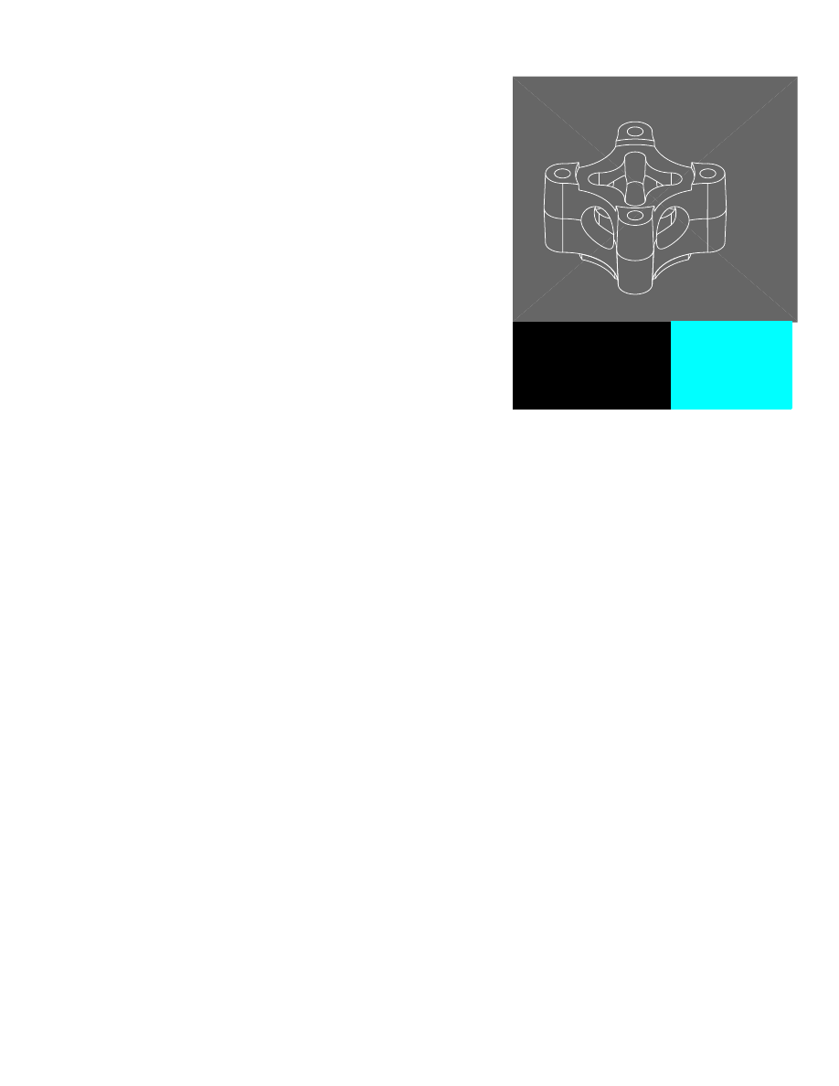
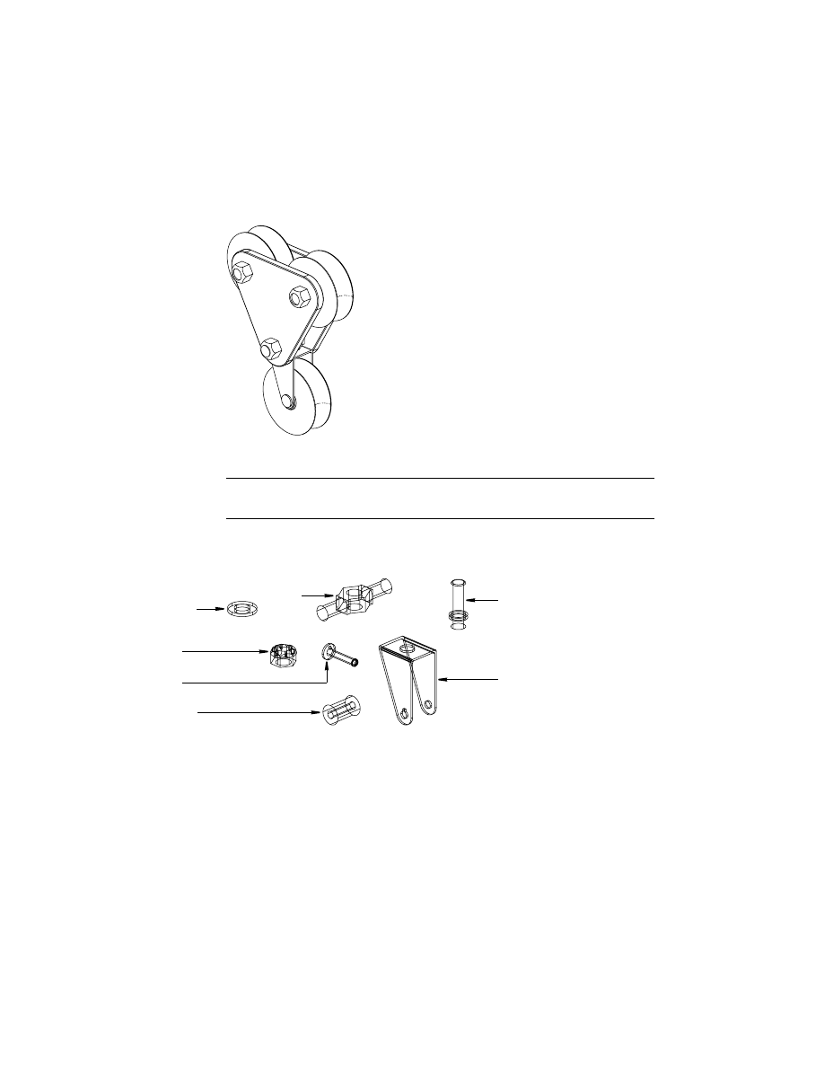
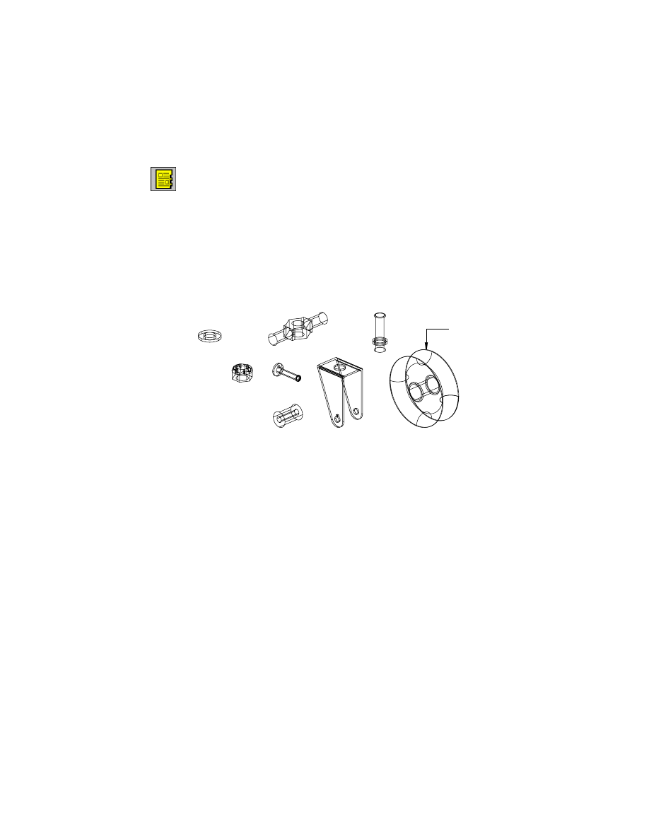
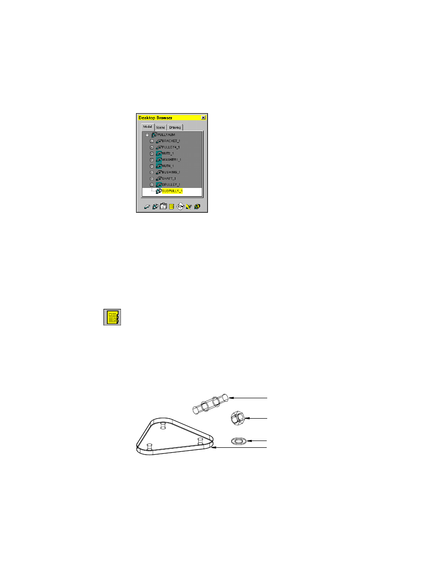
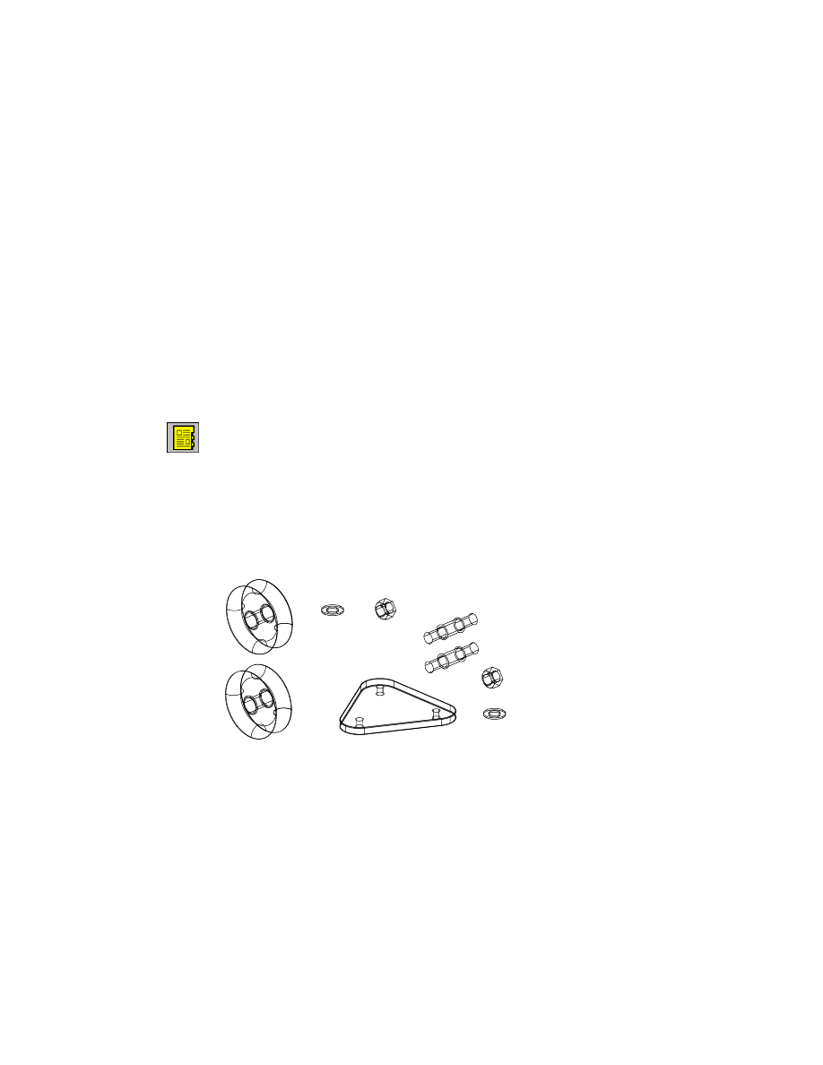
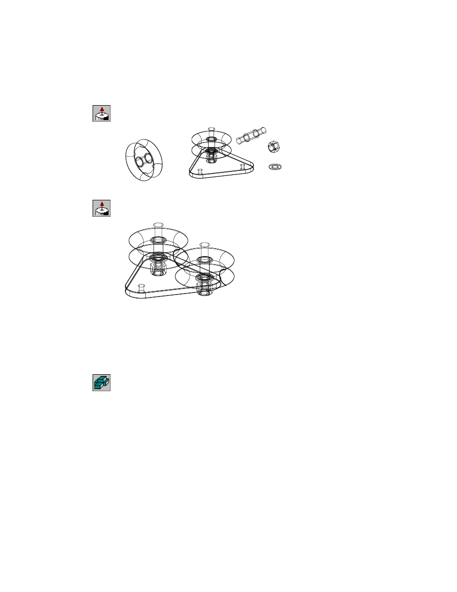
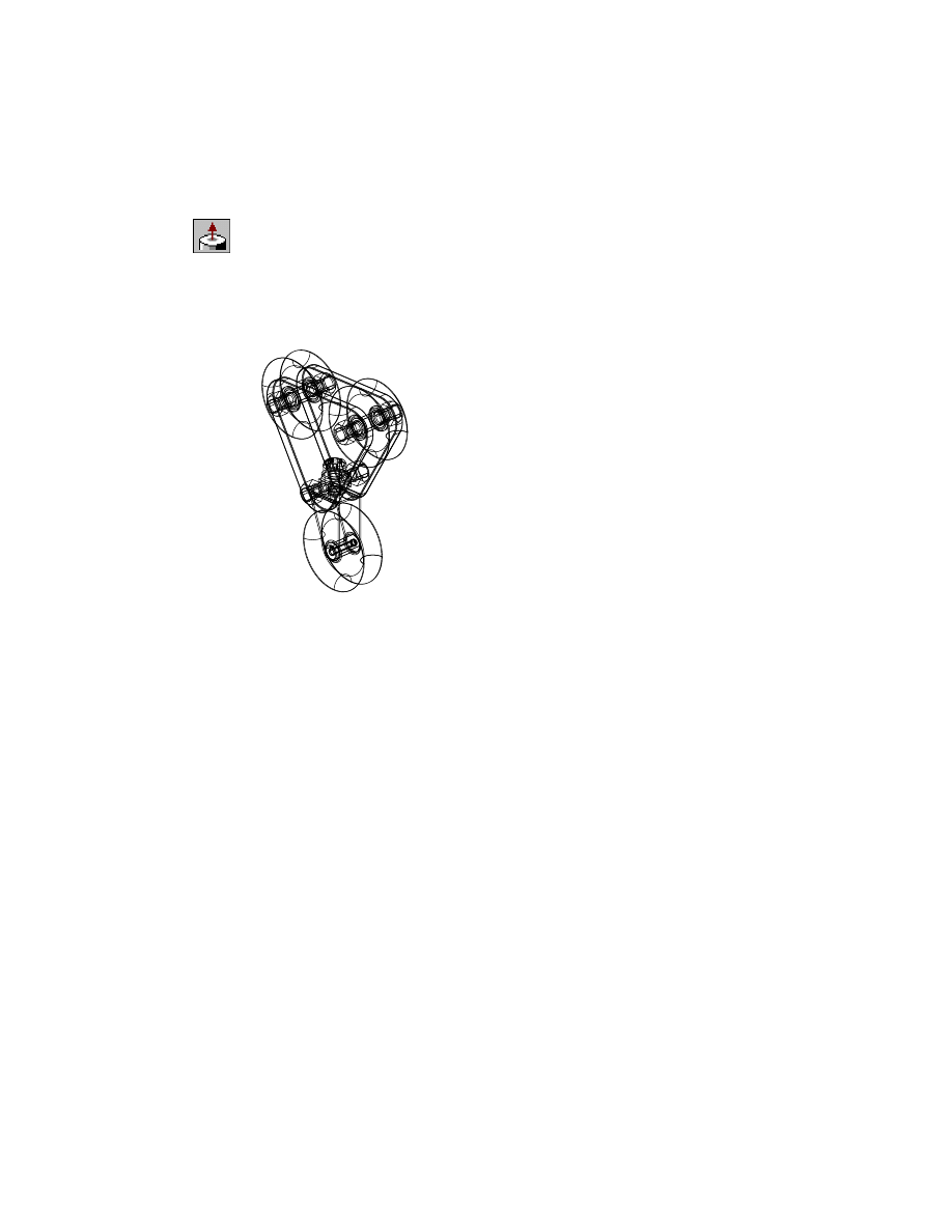
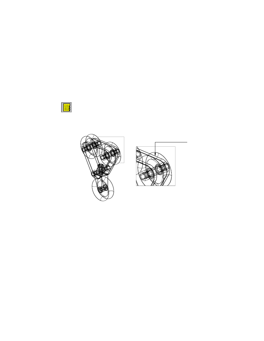
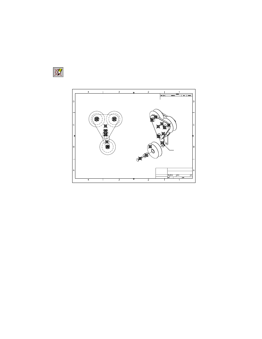
This drawing contains one local part, a bracket, and six external parts—a pul-
ley, a washer, a shaft, a bushing, and two nuts.
pulley4
bracket
nut2
washer1
nut4
shaft
bushing
Creating Local and External Parts
|
481
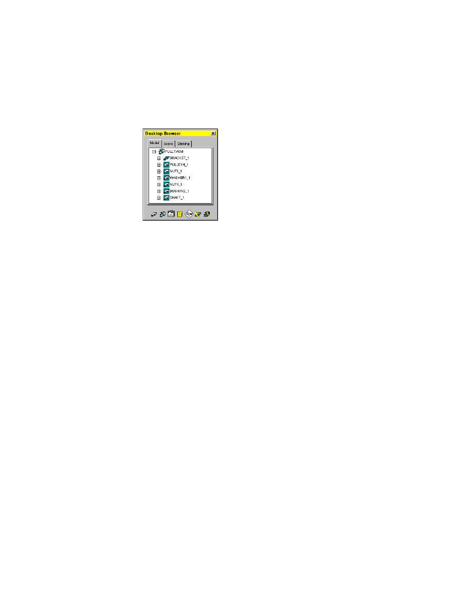
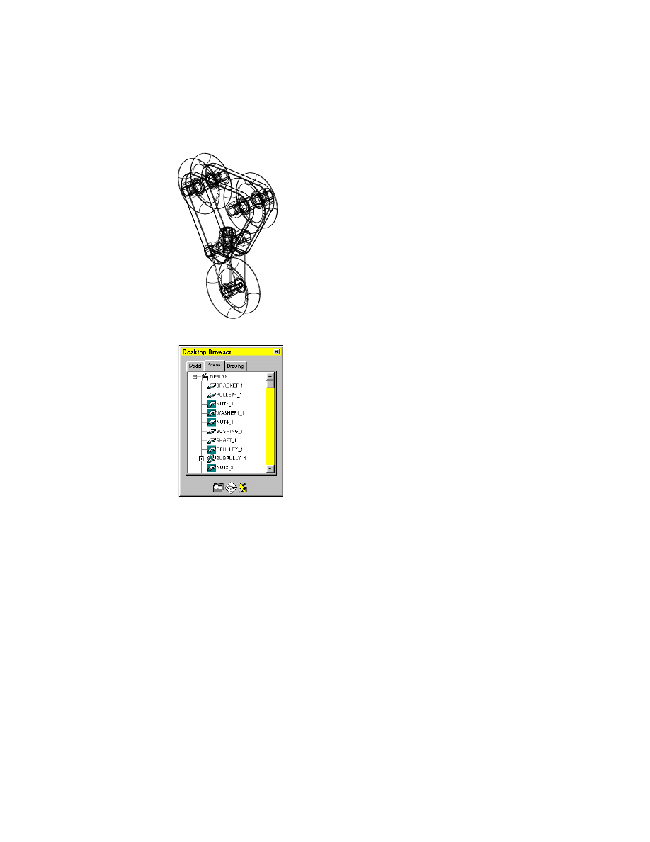
In the Desktop Browser, click the plus sign next to
PULLYASM. The assembly
tree expands to reveal the part files in the order in which they were added,
or referenced, into the file pullyasm.dwg.
In the Browser, each part is followed by a number that indicates the order in
which it was instanced. In this case, each part has only one instance. As you
add more instances, each one will be numbered incrementally. Icons with a
teal background are externally referenced parts.
Creating Local and External Parts
An assembly consists of a combination of existing or new parts and local and
external parts. You create local parts in the current assembly file.
You use the Assembly Catalog to manage existing local parts and to create
new external part references and new local parts. You can use the Browser for
quick access to the localize and externalize functions without opening the
Assembly Catalog.
482
|
Chapter 18
Assembling Complex Models
To localize a part
1
Localize the
PULLEY4
,
BUSHING,
and
SHAFT
parts.
Browser
Press CRTL and select
PULLEY4
,
BUSHING,
and
SHAFT
.
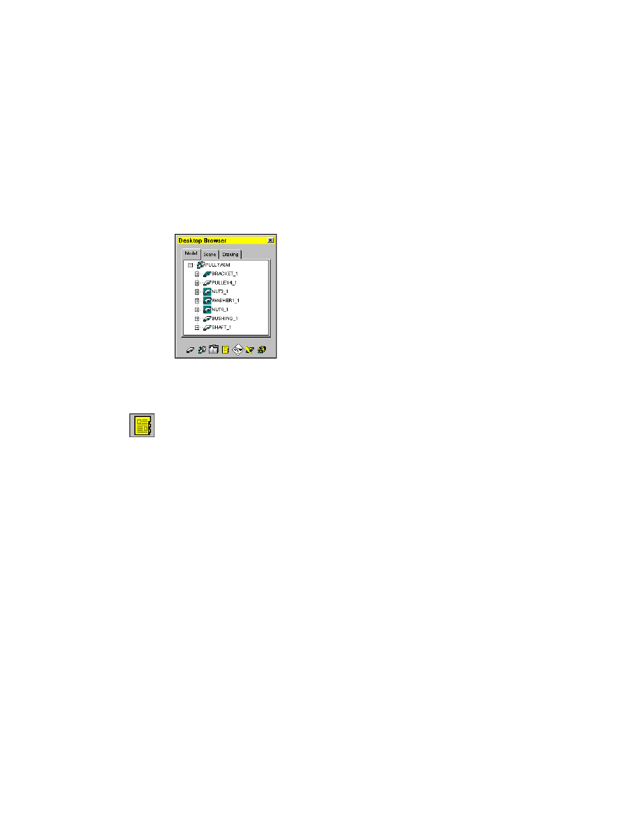
Right-click PULLEY4 and choose All Instances ➤ Localize.
In the Browser, note that the PULLEY4, BUSHING
,
and SHAFT icons no
longer have a teal background, which indicates that the externally referenced
Mechanical Desktop
®
parts are now local parts.
Links to the external files are severed. Any changes made to these parts affect
only the instances in the current assembly.
2
Check the Assembly Catalog to see how the localized parts are displayed.
Context Menu
In the graphics area, right-click and choose Catalog.
Choose the All tab. The PULLEY4, BUSHING
,
SHAFT and BRACKET are listed
under Local Assembly Definitions.
Choose OK.
When you have a library of existing parts, bring the files containing those
parts into the assembly drawing, and localize them. Parts that may change
should be externally referenced so that if the original part is changed, the
change will be reflected in the assembly drawing.
Applying Assembly Constraints
|
483
To reference an external part
1
Use
AMCATALOG
to reference an external part.
Context Menu
In the graphics area, right-click and choose Catalog.
In the Assembly Catalog, choose the External tab.
2
In Directories, right-click and choose Add Directory.
Select the desktop\tutorial folder, and choose OK.
All the part and assembly files in the folder are displayed; the icon in front of
each file indicates whether it is a part file or an assembly file.
3
Clear the Return to Dialog check box.
4
In Part and Subassembly Definitions, right-click DPULLEY and choose Attach.
5
In the graphics area on your screen, specify an insertion point and press
ENTER
.
DPULLEY is now externally referenced and instanced into your copy of the
pullyasm.dwg file.
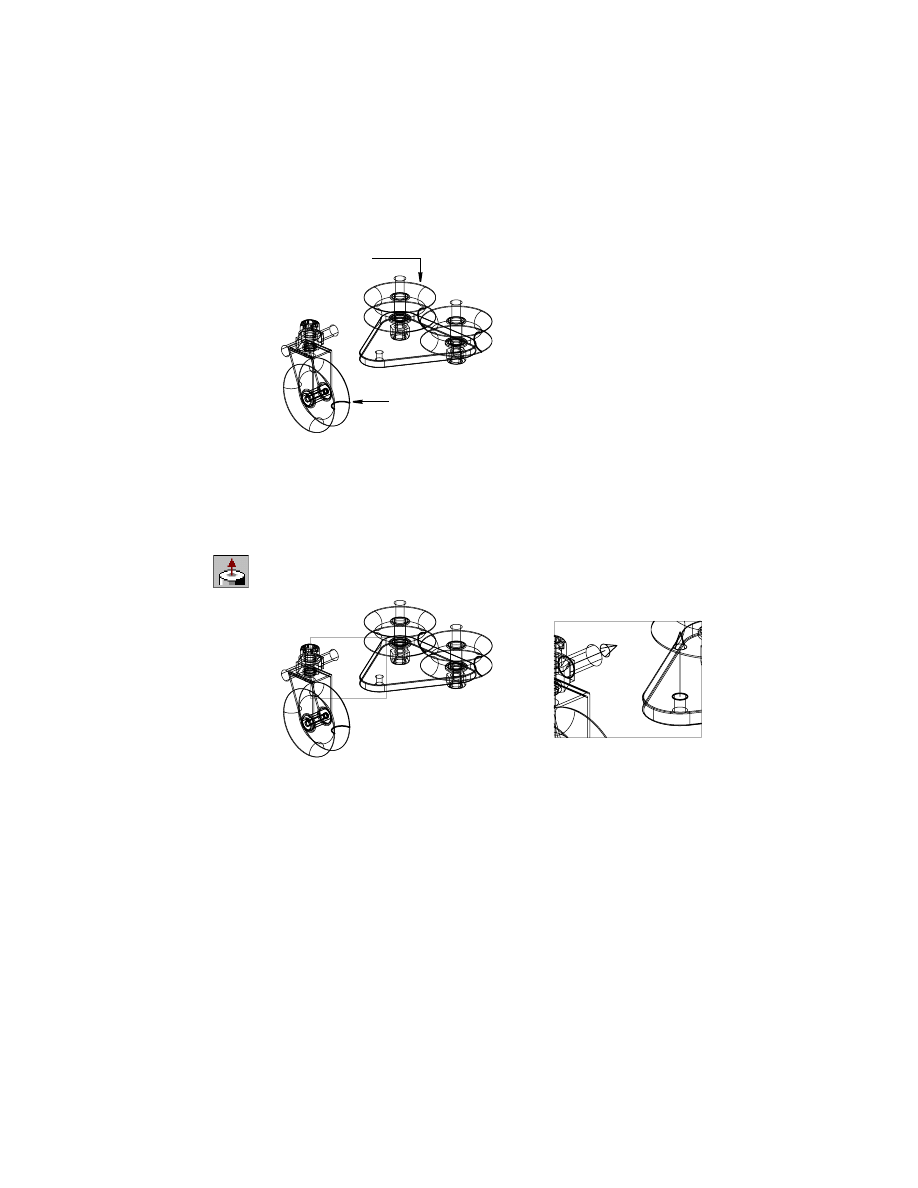
Applying Assembly Constraints
Now that the parts are referenced or localized into the assembly drawing, you
build the assembly by applying assembly constraints. You apply them to one
part at a time, removing degrees of freedom. The more constraints a part has,
the less freedom of movement it has.
You link the parts, one by one, like a chain, by constraining each part to
another part. Use the DOF symbol to illustrate how many degrees of freedom
are removed. Usually, you need to solve at least 2 degrees of freedom to suf-
ficiently constrain a part.
Zoom in as needed to make selection points easier to see. First, you constrain
the pulley to the bracket along the common axes. Then, you add another
constraint, to mate the planes of the two parts.
dpulley
484
|
Chapter 18
Assembling Complex Models
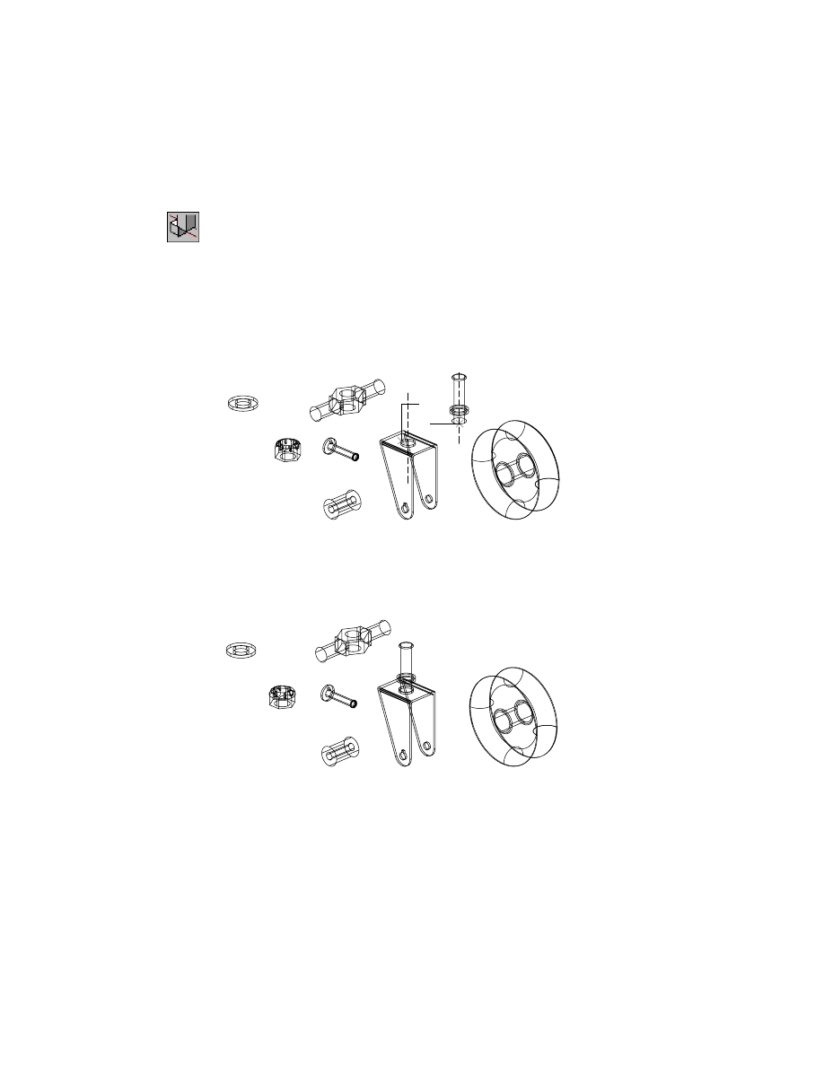
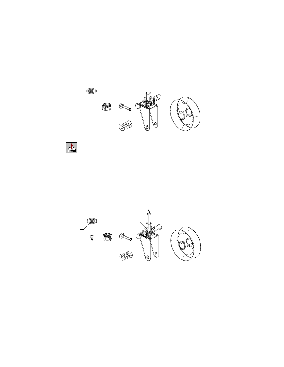
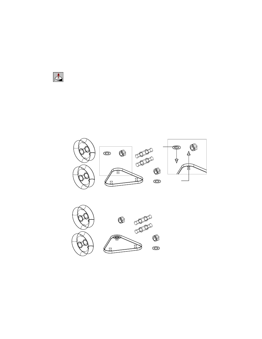
To constrain part faces along their axes using mate
1
Use
AMMATE
to constrain the part faces, responding to the prompts.
Context Menu
In the graphics area, right-click and choose 3D
Constraints ➤ Mate.
Select first set of geometry:
Select a cylindrical face on BRACKET (1)
First set = Axis, (arc)
Select first set or [Clear/fAce/Point/cYcle] <accEpt>:
Press
ENTER
Select second set of geometry:
Select a cylindrical face on PULLEY4 (2)
Second set = Axis, (arc)
Select second set or [Clear/fAce/Point/cYcle] <accEpt>:
Press
ENTER
Enter offset <0.0000>:
Press
ENTER
To select the geometry to be constrained, enter responses on the command
line, or use the animated mouse. Click the left (red) mouse button to cycle
through the options. Click the right (green) mouse button to select an option.
The PULLEY4 part is partially constrained to the BRACKET part along the
common axes.
2
1
Applying Assembly Constraints
|
485
You can move parts to make selection easier. The parts are automatically
reassembled when you add a constraint. Or, to manually reassemble parts,
set
AMAUTOASSEMBLE
to 0 (off). Use the Assembly Update icon in the
Browser to reassemble the parts after you finish adding constraints.
2
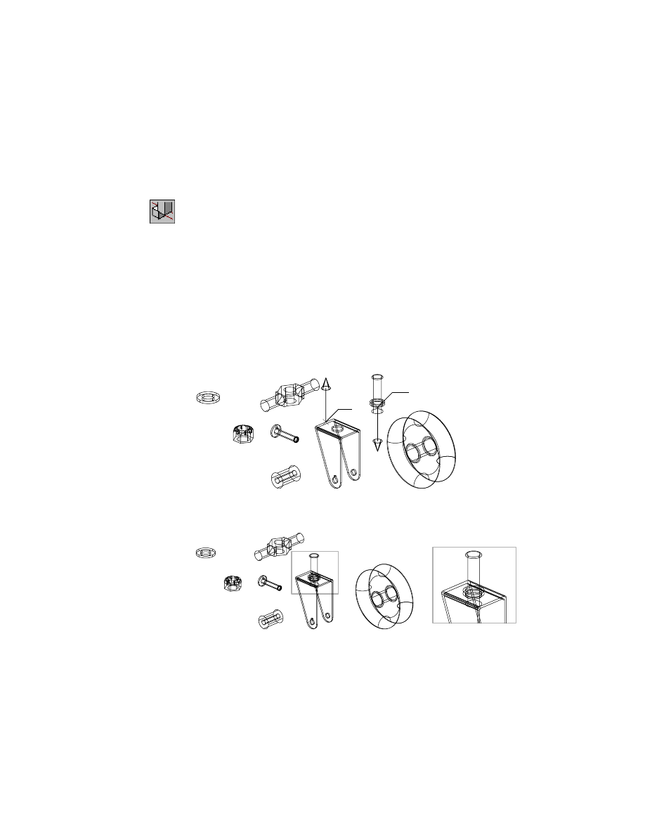
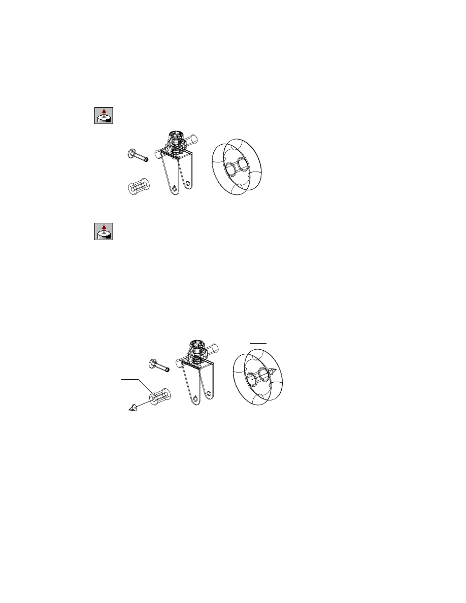
Mate the parts on facing planes, responding to the prompts.
Context Menu
In the graphics area, right-click and choose 3D
Constraints ➤ Mate.
Select first set of geometry:
Specify the top plane on BRACKET (3)
Select first set or [Clear/aXis/fAce/Next/cYcle] <accEpt>:
Enter a
First set = Plane
Enter an option [Clear/Next/Flip/cYcle] <accEpt>:
Cycle to point arrow away from the part, then press
ENTER
Select second set of geometry:
Specify the flange on PULLEY4 (4)
Second set = Axis, (arc)
Select second set or [Clear/fAce/Point/cYcle] <accEpt>:
Enter a
Second set = Plane
Enter an option [Clear/aXis/Point/Next/Flip/cYcle] <accEpt>:
Press
ENTER
Enter offset <0.0000>:
Press
ENTER
You have constrained BRACKET and PULLEY4 along the common axes and
mating planes.
The constraints are illustrated in the Desktop Browser as you create them,
showing the other part the constraint is applied to.
4
3
486
|
Chapter 18
Assembling Complex Models
To make it easier to see the constraints you have applied, select the Assembly
filter in the Browser. Then, the features are hidden, and only the assembly
constraints are displayed.
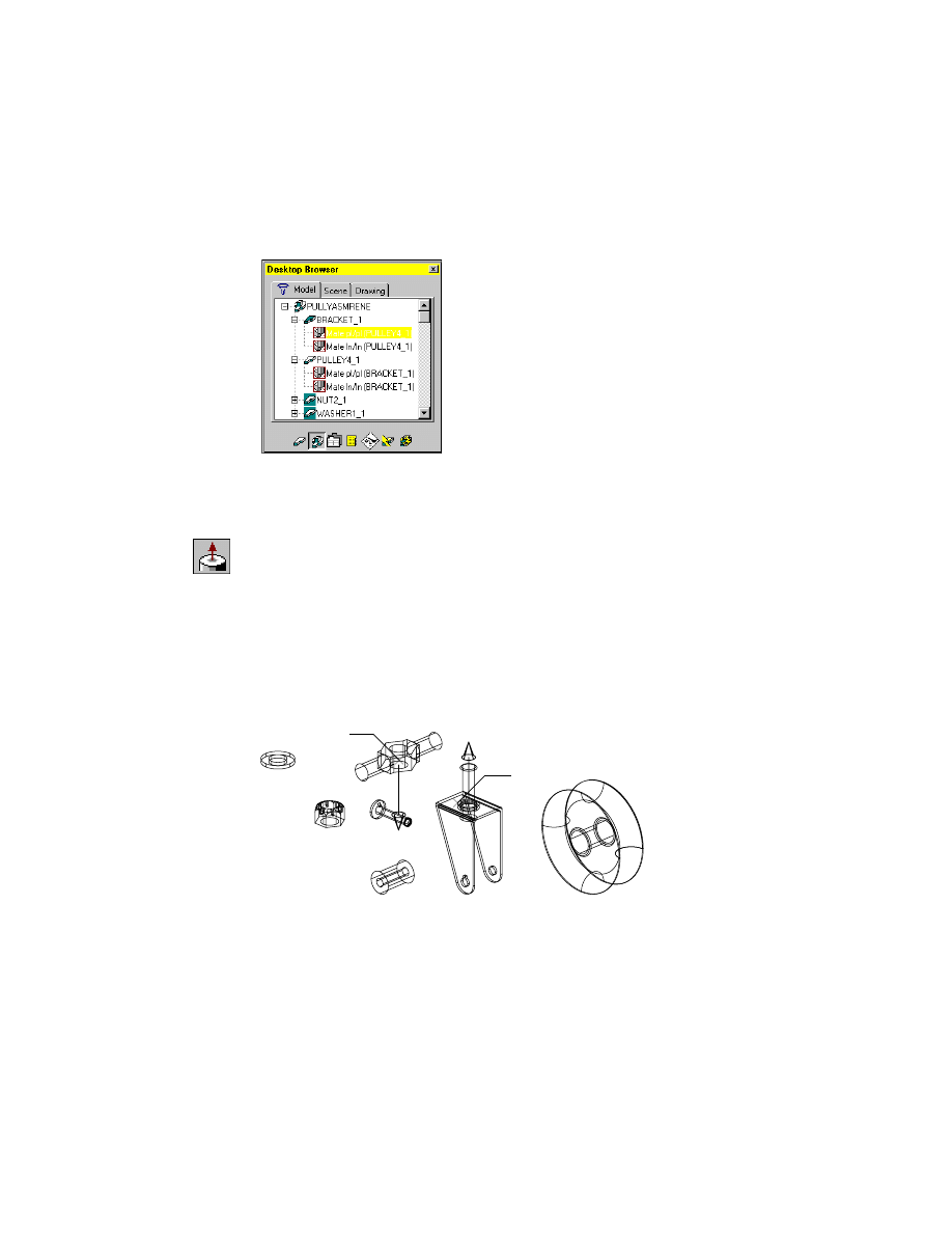
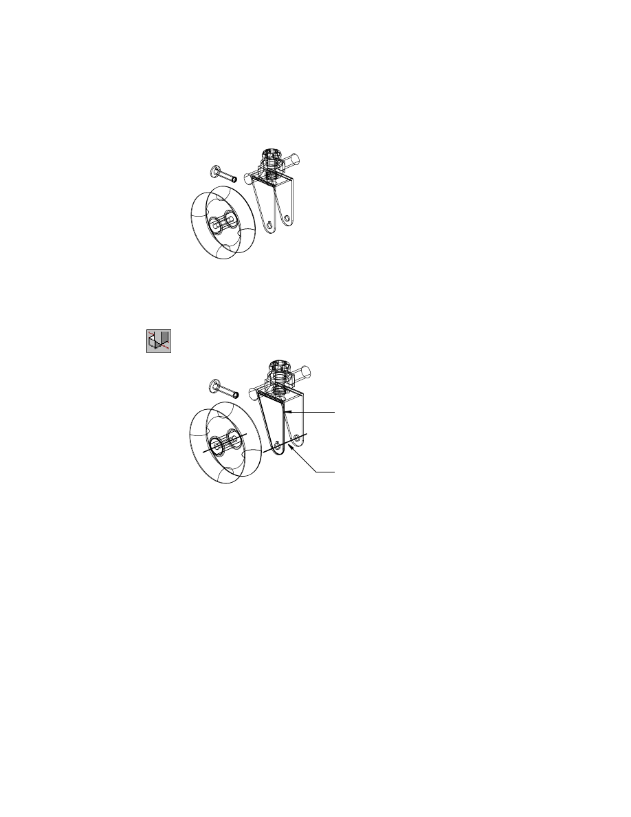
To constrain part faces along their axes using Insert
1
Use
AMINSERT
to constrain the part faces along the common axes and corre-
sponding planes, responding to the prompts.
Context Menu
In the graphics area, right-click and choose 3D
Constraints ➤ Insert.
Select first circular edge:
Specify the hole on NUT2 (5)
First set = Plane/Axis
Enter an option [Clear/Flip] <accEpt>:
Press
ENTER
Select second circular edge:
Specify the hole on the top flange of PULLEY4 (6)
Second set = Plane/Axis
Enter an option [Clear/Flip] <accEpt>:
Press
ENTER
Enter offset <0.0000>:
Press
ENTER
6
5
Applying Assembly Constraints
|
487
Using the insert constraint removes the same degrees of freedom as
constraining planes and axes separately. This is particularly useful for bolt-in-
hole type constraints.
The NUT2 part is constrained to BRACKET and PULLEY4 along the common
axes and mating planes.
2
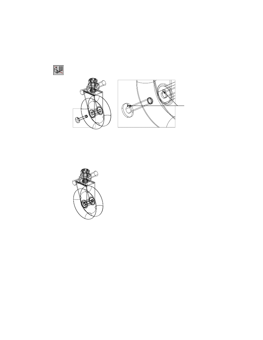
Constrain WASHER1 to NUT2, responding to the prompts.
Context Menu
In the graphics area, right-click and choose 3D
Constraints ➤ Insert.
Zoom in as needed to see the arrows that indicate the direction of insertion.
Select first circular edge:
Specify a point on WASHER1 (7)
First set = Plane/Axis
Enter an option [Clear/Flip] <accept>:
Press
ENTER
Select second circular edge:
Specify the hole on NUT2 (8)
Second set = Plane/Axis
Enter an option [Clear/Flip] <accept>:
Flip the direction arrow as needed, and press
ENTER
Enter offset <0.0000>:
Press
ENTER
WASHER1 is constrained to NUT2. Next, constrain NUT4 to WASHER1 along
the common axes and mating planes.
7
8
488
|
Chapter 18
Assembling Complex Models
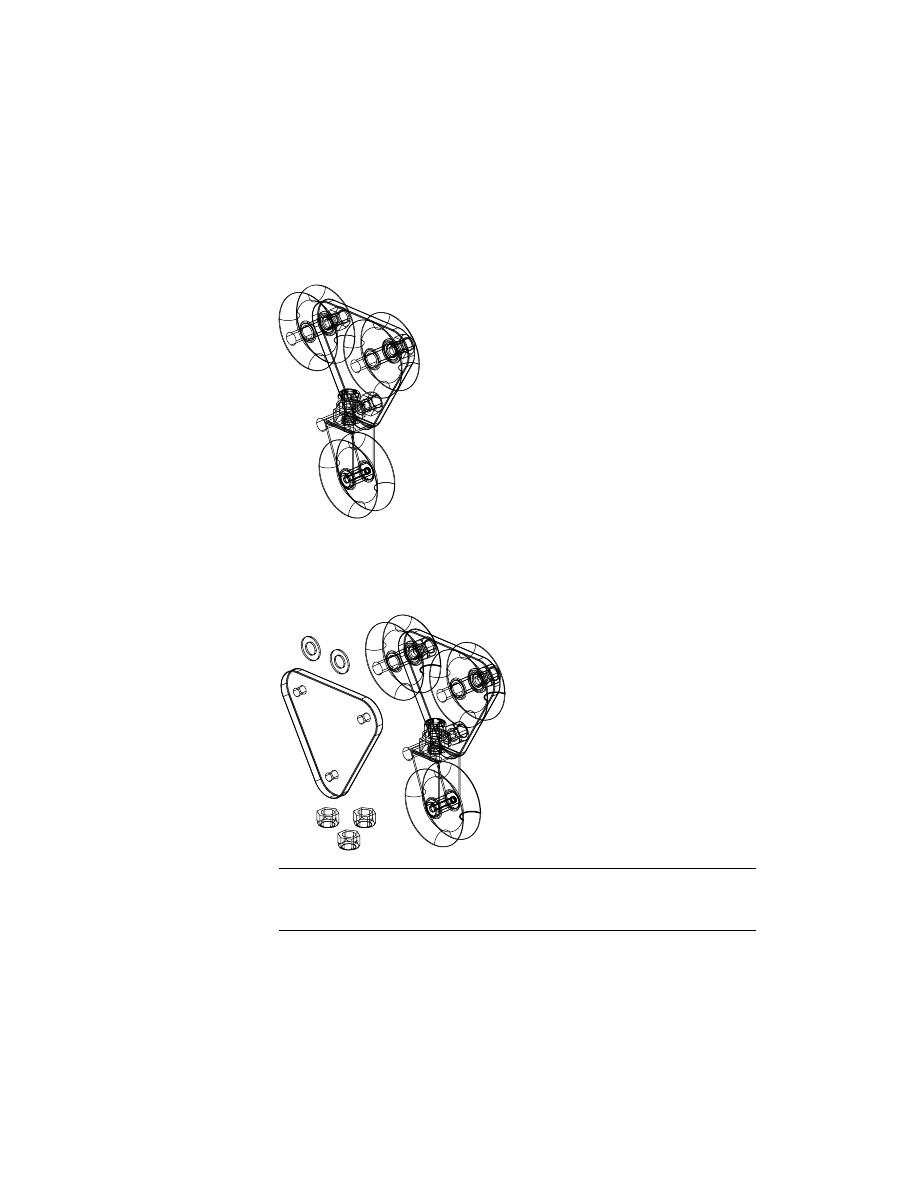
3
Constrain NUT4 to WASHER1.
Context Menu
In the graphics area, right-click and choose 3D
Constraints ➤ Insert.
4
Constrain BUSHING and DPULLEY along the common axes, responding to
the prompts.
Context Menu
In the graphics area, right-click and choose 3D
Constraints ➤ Insert.
Select first circular edge:
Specify a point on BUSHING (9)
First set = Plane/Axis
Enter an option [Clear/Flip] <accept>:
Press
ENTER
Select second circular edge:
Specify the hole on DPULLEY (10)
Second set = Plane/Axis
Enter an option [Clear/Flip] <accept>:
Enter f to flip the direction arrow away from BUSHING
Second set = Plane/Axis
Enter an option [Clear/Flip] <accept>:
Press
ENTER
Enter offset <0.0000>:
Press
ENTER
9
10
Applying Assembly Constraints
|
489
DPULLEY is constrained to BUSHING.
To apply final mate constraints
1
Use
AMMATE
to constrain DPULLEY and BUSHING to BRACKET with two
constraints: one to mate planes and one to mate along their axes. If you need
to, refer to “To constrain part faces along their axes using mate” on page 484.
Context Menu
In the graphics area, right-click and choose 3D
Constraints ➤ Mate.
mating plane
mating line
490
|
Chapter 18
Assembling Complex Models
2
Use
AMMATE
to constrain SHAFT to BRACKET along the left vertical line of
the notch.
Context Menu
In the graphics area, right-click and choose 3D
Constraints ➤ Mate.
The rotational degree of freedom is removed.
Save your file.
The parts are assembled, and all required degrees of freedom are solved by the
constraints.
3
Change to a top view and then to a right view, to verify that the parts are
positioned correctly.
Use the Browser to delete unwanted assembly constraints. Right-click the
Constraint icon, and choose Delete. You can then apply new constraints.
Next, create a new part to use as part of a subassembly.
mating lines
Creating New Parts
|
491
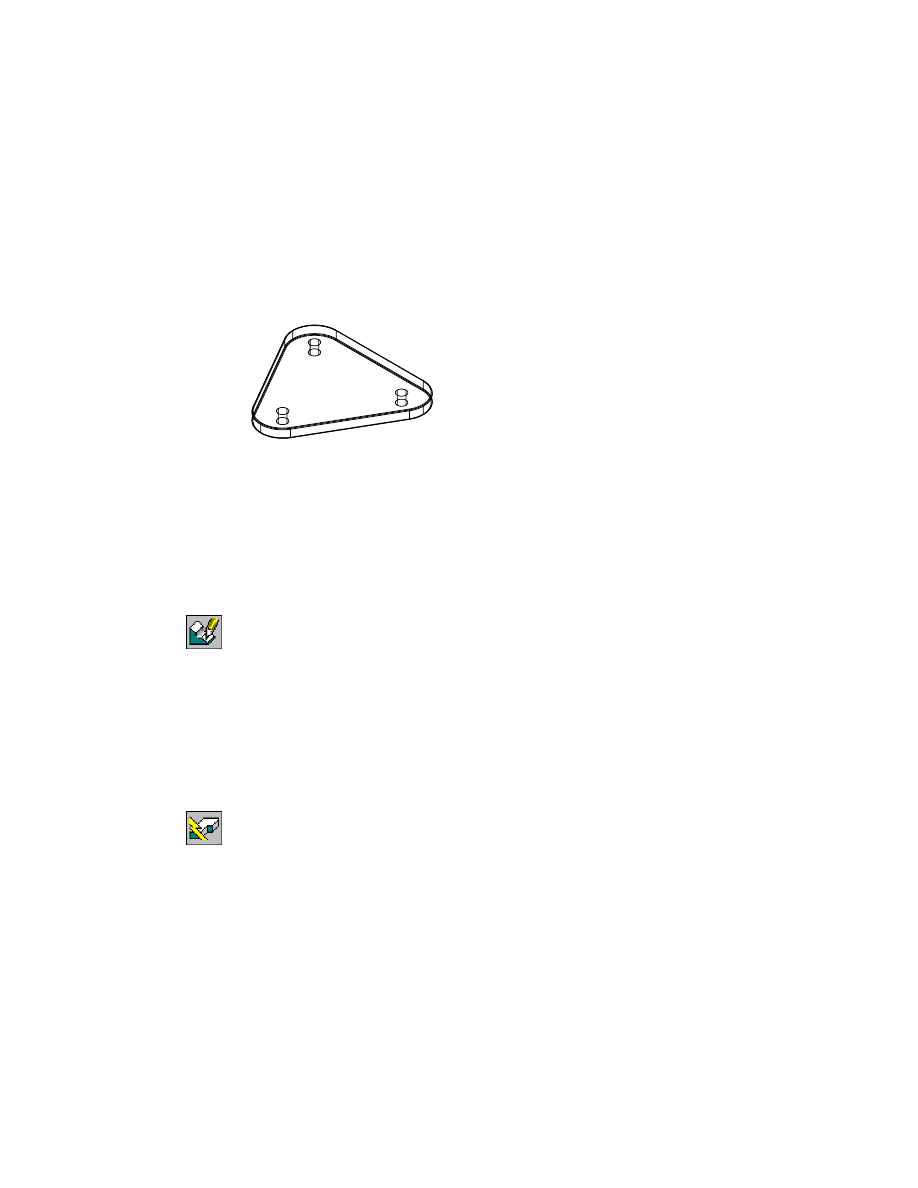
Creating New Parts
Before you build the subassembly, you create a pulley plate part. First, you
open a part file containing a constrained profile. Because you can have more
than one drawing open at a time in Mechanical Desktop, you do not need to
close your assembly file. In the part file, you add thickness to the profile and
create additional features so that you can use it as a subassembly in your
assembly.
Open the file ppulley.dwg.
NOTE
Back up the tutorial drawing files so you still have the original files if you
make a mistake. See “Backing up Tutorial Drawing Files” on page 40.
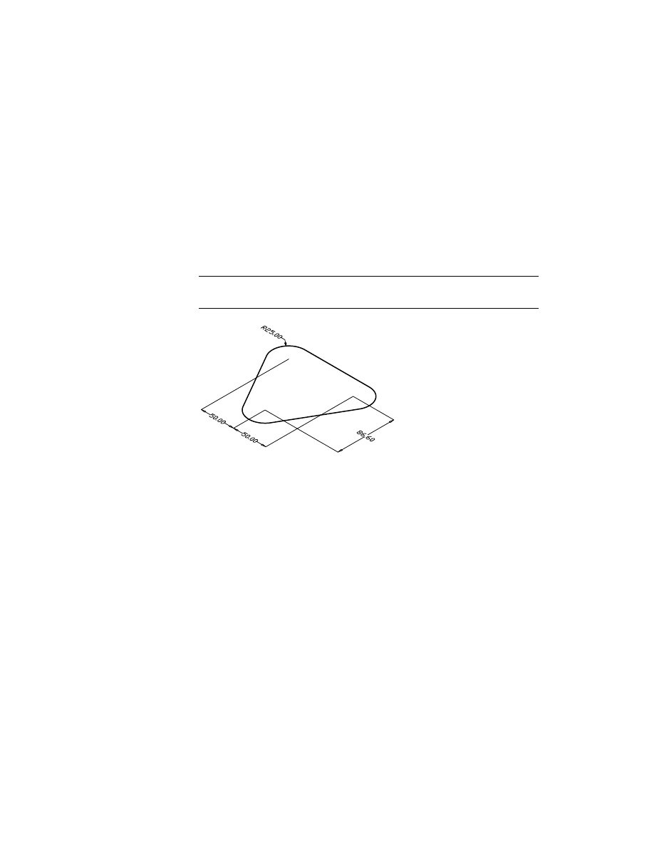
The sketch of the pulley plate has already been profiled and constrained, so
you only need to extrude it. Extrusion adds thickness to a constrained profile.
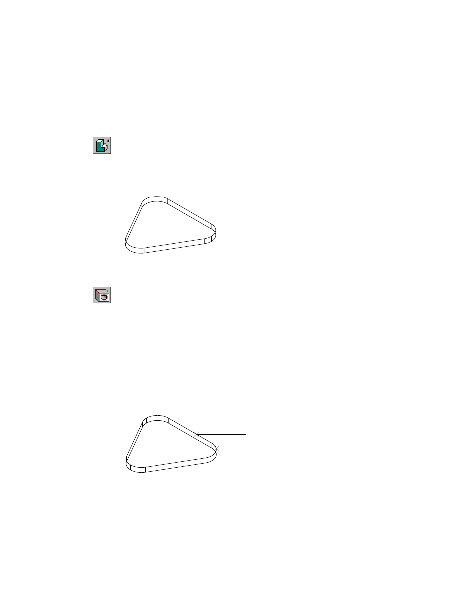
492
|
Chapter 18
Assembling Complex Models
To extrude a sketch
1
Expand the feature hierarchy in the Browser by clicking the plus sign in front
of PPULLEY_1.
2
Use
AMEXTRUDE
to extrude the profile.
Context Menu
In the graphics area, right-click and choose Sketched &
Work Features ➤ Extrude.
3
In the Extrusion dialog box, specify:
Distance:
Enter 10
Choose OK to create the extrusion.
To add a placed feature to a part
1
Use
AMHOLE
to add three drilled bolt holes to the pulley plate.
Context Menu
In the graphics area, right-click and choose Placed
Features ➤ Hole.
In the Hole dialog box, select the Drilled hole type icon, and specify:
Termination:
Through
Placement:
Concentric
Diameter:
Enter 10
Choose OK.
2
Continue on the command line.
Select work plane, planar face or [worldXy/worldYz/worldZx/Ucs]:
Select the pulley plate edge (1)
Enter an option (Next/accEpt) <accEpt>:
Press
ENTER
Select concentric edge:
Select the arc (2)
1
2
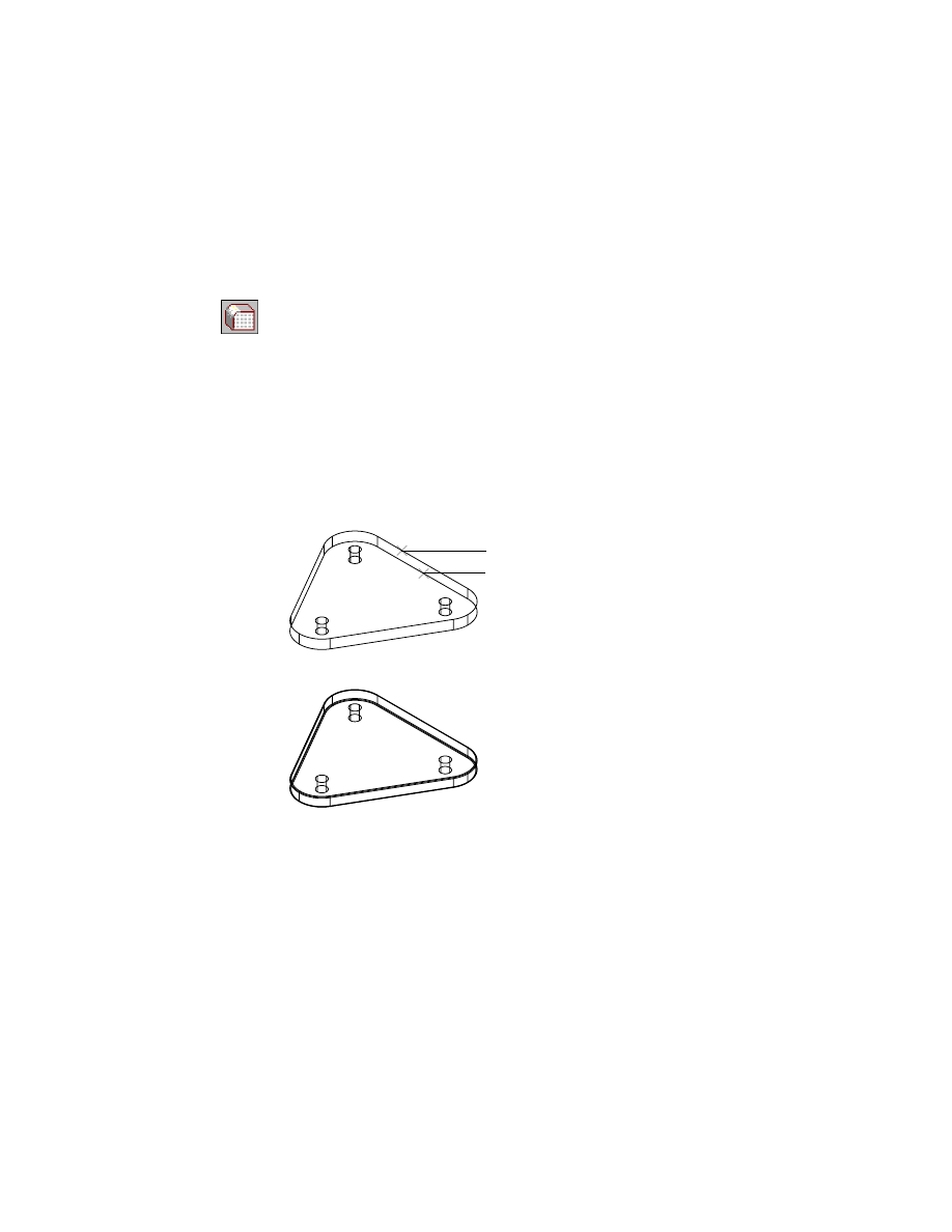
Creating New Parts
|
493
3
Continue placing two more holes concentric to the remaining arcs. Then
press
ENTER
.
The drilled holes are added and cut through the pulley plate. Later, you check
for interference and modify the diameter of the holes.
4
Use
AMFILLET
to fillet the pulley plate edges.
Context Menu
In the graphics area, right-click and choose Placed
Features ➤ Fillet.
In the Fillet dialog box, select the Constant check box and specify:
Radius:
Enter 1
Return to dialog:
Clear the check box
Choose OK.
5
Respond to the prompts as follows:
Select edges or faces to fillet:
Select the pulley plate top edge (1)
Select edges or faces to fillet:
Select the pulley plate bottom edge (2)
Select edges or faces to fillet:
Press
ENTER
The pulley plate edges are filleted.
Now that the pulley plate is complete, you have all the parts you need to
build the subassembly.
Save your file, but do not close it. You will make some changes to it later.
1
2
494
|
Chapter 18
Assembling Complex Models
Creating Subassemblies
You created an assembly. Now, you will create a subassembly. Each subassem-
bly contains one or more parts or subassemblies. In the Browser, subassem-
blies and parts are nested under the assembly.
You create, instance, and constrain parts into a subassembly just as you do
into an assembly. Once the subassembly is created, it is constrained to the
assembly, completing the assembly model.
Defining and Activating Subassemblies
Before you can instance any parts into the subassembly, you must create and
activate a subassembly definition and then load and instance external part
drawings as the parts for the subassembly.
To create and activate a new subassembly
1
Switch to the window containing your assembly.
2
Activate the assembly, PULLYASM.
Browser
Right-click PULLYASM and choose Activate.
3
In the Browser, collapse the feature hierarchy.
Browser
Right-click PULLYASM and ➤ Collapse. Then click the
plus sign in front of PULLYASM.
4
Create a new subassembly definition, responding to the prompt.
Context Menu
In the graphics area, right-click and choose Assembly ➤
New Subassembly.
Enter new subassembly name <SUB1>:
Enter subpully
The Desktop Browser adds a subassembly called SUBPULLY_1 to the assembly
tree. Because there are no parts instanced or files attached, the subassembly
location is empty.
5
Activate the new subassembly, responding to the prompt.
Context Menu
In the graphics area, right-click and choose Assembly ➤
Activate Assembly.
Enter assembly name to activate or [?] <PULLYASM>:
Enter subpully_1
Creating Subassemblies
|
495
The inactive PULLYASM assembly is shaded in the Desktop Browser, and the
SUBPULLY subassembly is active.
The active subassembly name is displayed below the command line (Target:
SUBPULLY).
Using External Parts
Now that you have activated the new subassembly, you use external parts to
create the subassembly.
To attach an external part drawing as an external part
1
Use
AMCATALOG
to attach an external part.
Context Menu
In the graphics area, right-click and choose Catalog.
In the Assembly Catalog, choose the External tab. Verify that tutorial is listed
in Directories and that Return to Dialog is selected.
2
Double-click the file ppulley.dwg.
3
Position the pulley plate on the screen, and press
ENTER
.
The pulley plate is attached to the SUBPULLY subassembly.
4
In the Assembly Catalog, right-click DPULLEY3 and choose Attach.
5
Attach WASHER3 and NUT3.
dpulley3
nut3
washer3
ppulley
496
|
Chapter 18
Assembling Complex Models
Notice that an attached part is indicated by a white background in the
Assembly Catalog.
Choose OK.
Examine the Browser. The referenced parts are nested under the new sub-
assembly hierarchy.
Instancing Parts
You have already attached parts to the subassembly. Each part definition is
listed in the Assembly Catalog. When you instance a part in the current
assembly, it refers to its part definition in the Catalog. Once a part is
instanced into the subassembly, you can copy it from the Browser.
To instance a part
1
Use
AMCATALOG
to instance a part.
Context Menu
In the graphics area, right-click and choose Catalog.
In the Assembly Catalog, choose the All tab. In External Assembly Definitions,
select DPULLEY and verify that Return to Dialog is selected.
2
Insert a copy of DPULLEY, and choose OK to exit the Assembly Catalog.
3
Use the Browser to create another instance of DPULLEY.
Browser
Right-click DPULLEY and choose Copy. In the graphics
area, click a location for the copy and press
ENTER
.
4
Make one copy each of DPULLEY3, WASHER3, and NUT3.
The Browser is updated to include the new instances.
Save your file.
Next, apply assembly constraints to build the subassembly.

Completing Assemblies
|
497
Completing Assemblies
Now that the parts are instanced into the subassembly, you can complete the
subassembly and constrain it to the base assembly. When the entire assembly
is complete, check it for interference among parts, and obtain mass property
information.
NOTE
The Desktop Browser shows the order in which parts and subassemblies
are assembled. You can drag a part or subassembly to a different position in the
Desktop Browser. Always save your file before you reorder the hierarchy.
Reordering may affect offsets for explosion factors in scenes.
Applying Assembly Constraints
First, constrain parts in the subassembly, and then constrain the subassembly
to the base assembly.
The instructions specify responses on the command line for constraint appli-
cation, but if you prefer, you can use the animated cursor. After you select the
object to constrain, click the left mouse button (red) to cycle through the
options. When the object you want is highlighted, click the right mouse
button (green) to accept the selection.
498
|
Chapter 18
Assembling Complex Models
To constrain a subassembly part
1
Use AMINSERT to constrain WASHER3 to PPULLEY, responding to the
prompts.
Context Menu
In the graphics area, right-click and choose 3D
Constraints ➤ Insert.
Select first circular edge:
Specify the hole on the bottom of WASHER3 (1)
First set = Plane/Axis
Enter an option [Clear/Flip] <accept>:
Enter f, if needed
First set = Plane/Axis
Enter an option [Clear/Flip] <accept>:
Press
ENTER
Select second circular edge:
Specify the top cylindrical edge of the hole in PPULLEY (2)
Second set = Plane/Axis
Enter an option [Clear/Flip] <accept>:
Press
ENTER
Offset <0.0000>:
Press
ENTER
WASHER3
is constrained to PPULLEY along common axes and mating
planes.
1
2
Completing Assemblies
|
499
2
Constrain DPULLEY to WASHER3, responding to the prompts.
Context Menu
In the graphics area, right-click and choose 3D
Constraints ➤ Insert.
Select first circular edge:
Specify inner edge of hole on DPULLEY (1)
First set = Plane/Axis
Enter an option [Clear/Flip] <accept>:
Enter f
First set = Plane/Axis
Enter an option [Clear/Flip] <accept>:
Press
ENTER
Select second circular edge:
Specify the top cylindrical edge of WASHER3 (2)
Second set = Plane/Axis
Enter an option [Clear/Flip] <accept>:
Press
ENTER
Offset <0.0000>:
Press
ENTER
The DPULLEY part is constrained to WASHER3 along the common axes and
mating planes.
1
2
500
|
Chapter 18
Assembling Complex Models
3
Constrain DPULLEY3 and NUT3 to the subassembly.
Context Menu
In the graphics area, right-click and choose 3D
Constraints ➤ Insert.
4
Constrain the remaining parts to finish the subassembly.
Context Menu
In the graphics area, right-click and choose 3D
Constraints ➤ Insert.
Save your file.
Next, activate the top level of the assembly and constrain the subassembly to
the top assembly.
To constrain a subassembly to a top-level assembly
1
Use
AMACTIVATE
to activate the PULLYASM assembly, responding to the
prompt.
Context Menu
In the graphics area, right-click and choose Assembly ➤
Activate Assembly.
Enter assembly name to activate or [?] <PULLYASM>:
Press
ENTER
Completing Assemblies
|
501
In the Desktop Browser, the top-level assembly is no longer shaded.
The active assembly name is displayed below the command line (Target:
PULLYASM).
2
Move the subassembly, to make viewing easier. Then zoom in as needed to
magnify selection points.
Next, constrain the pulley plate subassembly to the root assembly.
3
Choose Insert to constrain the shaft of NUT2 to the pulley plate hole on the
mating planes and along the common axes.
Context Menu
In the graphics area, right-click and choose 3D
Constraints ➤ Insert.
completed subassembly
completed root assembly
502
|
Chapter 18
Assembling Complex Models
The subassembly is now constrained to the root assembly.
Copy another instance of NUT3 in your drawing and constrain it to the shaft
of NUT2.
To add and constrain a part instance
1
Use the Browser to copy another instance of the NUT3 external part into the
assembly.
Browser
Right-click NUT3, and choose Copy. In the graphics area,
click a location for the copy, and press
ENTER
.
2
Constrain NUT3 to the pulley plate and the shaft of NUT2.
Context Menu
In the graphics area, right-click and choose 3D
Constraints ➤ Insert.
Completing Assemblies
|
503
It is a good idea to check the position of a constrained part in another view. If
the part is constrained incorrectly, use the Browser to delete the constraint.
Right-click to display the menu, and choose Delete. Then move the parts as
needed, and reapply the constraints.
One side of the pulley assembly is complete.
3
Repeat steps 1 and 2 to copy and apply assembly constraints to WASHER3,
PPULLEY, and NUT3, to complete the pulley assembly.
4
Add one instance of your copy of the PPULLEY external part, two copies of
WASHER3, and three copies of NUT3 into the assembly drawing.
NOTE
Depending on the current UCS of your drawing, the parts may not be
oriented the same as they are in the above illustration. This does not affect your
ability to place the constraints.
504
|
Chapter 18
Assembling Complex Models
5
Constrain both WASHER3 parts to the DPULLEY3 parts on the pulley plate.
Context Menu
In the graphics area, right-click and choose 3D
Constraints ➤ Insert.
6
Use Insert to constrain PPULLEY_2 to the WASHER3 parts.
Constrain PPULLEY to any two instances of WASHER3, to remove the rota-
tional degree of freedom from the pulley plate.
7
Use Insert again to constrain the NUT3 parts to the pulley plate.
Save your file. The pulley assembly is complete.
Restructuring Assemblies
The pulley assembly model in the previous exercise was planned, and then
assembled in a particular order. In Mechanical Desktop, you can use another
design process called assembly restructure. You can design and constrain parts
and create assemblies in any order, and subsequently adjust the assembly
structure within the Desktop Browser.
Using the assembly restructure feature in the Browser, you can
■
Use either the drag or cut and paste method to move components
■
Move components from the master assembly into a local or external sub-
assembly
■
Select multiple parts and subassemblies and move them within the
Browser to restructure the assembly
■
Move components while in the context of an active external subassembly

Completing Assemblies
|
505
In most cases, constraints are maintained with the parts and subassemblies
that you move. In the event that a constraint cannot be maintained, a warn-
ing message is displayed.
NOTE
Instances can be lost if you restructure them up the assembly hierarchy
where multiple instances of the same definition exist.
Open the assembly file pullyasm.dwg from the desktop\tutorial folder, and
practice using assembly restructure.
To restructure an assembly hierarchy
1
Expand the hierarchy in the Browser so you can see all of the components.
Browser
Right-click PULLYASM and choose Expand.
2
Select a part name to activate the part.
To select more than one part, hold down CTRL as you select.
To select all parts within a range, hold down SHIFT as you select the first and
last part in the range. All components in between are automatically selected.
3
Drag the selected parts up or down in the assembly structure.
Use a left-click to drag your selection to a location and release the mouse.
Use a right-click to drag your selection to a location and release the mouse to
display a context menu with options Move Here, Copy Here, Create Subas-
sembly Here, and Cancel.
If the assembly tree is too long to scroll conveniently, right-click the compo-
nent and choose Cut, scroll to the new location, and Choose paste.
If a part cannot be moved logically, an error icon is displayed.
When restructure is activated, the cursor changes to look like a shadow of the
original part name.
4
Drop the part in a valid destination.
Valid destinations are highlighted as you move the cursor over them.
The part is restructured within the assembly, and the assembly is updated.
506
|
Chapter 18
Assembling Complex Models
Analyzing Assemblies
Next, check for interference between parts. This analysis is useful for detect-
ing problems that may arise during the final design stages. Check each part
for interference. If any interference is detected between parts, interference
solids can be created to illustrate where the interference occurs.
To check for interference
1
Use
AMINTERFERE
to check for interference.
Context Menu
In the graphics area, right-click and choose Analysis ➤
Check Interference.
Respond to the prompts.
Nested part or subassembly selection? [Yes/No] <No>:
Enter y
Specify first set of parts or subassemblies or [?]:
Select PPULLEY (1)
Instance = PPULLEY_2
Enter an option [Down/Next/Accept] <Accept>:
Press
ENTER
Specify first set of parts or subassemblies:
Press
ENTER
Specify second set of parts or subassemblies:
Select DPULLEY3 (2)
Instance = SUBPULLY_1
Enter an option [Down/Next/Accept] <Accept>:
Enter d
Instance = DPULLEY3_1
Enter an option [Up/Down/Next/Accept] <Accept>:
Press
ENTER
Specify second set of parts or subassemblies:
Press
ENTER
Comparing 1 parts/subassemblies against 1 parts/subassemblies.
Interference 1:
PPULLEY_2
SUBPULLY_1
DPULLEY3_1
Create interference solids? [Yes/No] <No>:
Enter n
Highlight pairs of interfering part/subassemblies?[Yes/No] <No>:
Enter y
Enter an option [eXit/Next pair] <Next pair>:
Enter x
NOTE
Resize the text window above the command line to read the results of
interference checking.
Completing Assemblies
|
507
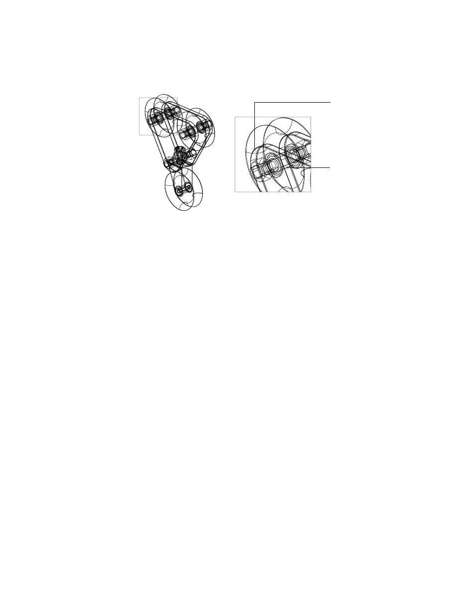
You should detect two examples of interference. Both DPULLEY and
WASHER3 parts interfere with the holes on PPULLEY. The drilled holes in the
pulley plate are too small.
The pulley plate is an external part, but it can be edited from within the
assembly file. If you are working in a very large assembly, it may be easier to
open the external file and make changes.
1
2
508
|
Chapter 18
Assembling Complex Models
Editing Mechanical Desktop Parts
Because interference was detected between the pulley plate and the
DPULLEY3 parts, you need to enlarge the drilled holes on the pulley plate.
Editing an external part updates all instances of the parts in the assembly
drawing. The modified part retains the applied assembly constraints.
In this tutorial, you return to the open ppulley.dwg file and make the holes
larger, to remove the interference.
To edit an external part
1
Switch to the window containing the PPULLEY part you created earlier.
2
In the Browser, click the plus sign in front of PPULLEY
to display the part
features.
3
Use
AMEDITFEAT
to edit the holes, responding to the prompts.
Context Menu
In the graphics area, right-click and choose Edit Features
➤ Edit.
Enter an option [Independent array instance/Sketch/surfCut/Toolbody/select
Feature] <select Feature>:
Select one of the drilled holes
Enter an option [Accept/Next] <Accept>:
Enter n or press
ENTER
The Hole dialog box is displayed.
4
In the Hole dialog box, enter 15 in the Drill Size field. Then choose OK.
5
Repeat steps 3 and 4 for Hole2 and Hole3.
6
Use
AMUPDATE
to update the edited part.
Context Menu
In the graphics area, right-click and choose Update Part.
The pulley plate reflects the new design.
Save your file.
Reloading External References
|
509
Reloading External References
To update the assembly to reflect the changes you made to the external part,
reload the external definition.
To reload an external definition
1
Switch to the window containing the assembly.
2
Use
AMCATALOG
to reload the PPULLEY definition.
Context Menu
In the graphics area, right-click and choose Catalog.
In the Assembly Catalog, in External Assembly Definitions, right-click
PPULLEY and choose Reload.
Choose OK.
The pulley plate reflects the new design.
If the assembly looks incorrect, choose Assembly ➤ Assembly Update to
update the assembly constraints.
Save your file.
Check the assembly again for interference.
redesigned part
510
|
Chapter 18
Assembling Complex Models
To check for interference
1
Use
AMACTIVATE
to activate the SUBPULLY subassembly.
Context Menu
In the graphics area, right-click and choose Assembly ➤
Activate Assembly.
Specify the SUBPULLY subassembly.
2
Use
AMINTERFERE
to check for interference.
Context Menu
In the graphics area, right-click and choose Analysis ➤
Check Interference.
3
Specify DPULLEY3. No interference should be detected.
Assigning Mass Properties
Next, calculate mass property information. You can analyze parts and assem-
blies during the course of designing. You may need to optimize weight, max-
imize stiffness, balance loads, ease assembly, or meet particular requirements.
One mass properties dialog box contains both Setup and Results tabs that
function the same for both parts and assemblies. In this case, the parts list in
the dialog box displays all parts and part properties in the activated assembly
to be analyzed. Item numbers are also displayed if a BOM exists. When you
select an item in the parts list, it is graphically highlighted on the screen.
In these steps, you analyze the bracket and change tolerance values and
material types.
To set up mass properties
1
Activate the PULLYASM assembly.
Context Menu
In the graphics area, right-click and choose Assembly ➤
Activate Assembly.
2
Use
AMMASSPROP
to analyze the mass properties of the assembly, responding
to the prompt.
Context Menu
In the graphics area, right-click and choose Analysis ➤
Mass Properties.
Select parts or subassemblies:
Select the bracket, and press
ENTER
The Assembly Mass Properties dialog box is displayed with the Setup tab
active. In the Materials Available window, the materials listed are all of those
defined in the active assembly.

Reloading External References
|
511
3
In the Assembly Mass Properties dialog box Setup tab, specify:
Output Units:
Metric (mm, g)
Coordinate System:
User coordinate system (UCS)
Display Precision:
Select 0.00000
Part Name:
Select BRACKET
Materials Available: Material:
Select Stainless_Steel
Choose Assign Material.
The material information is transferred to the part material attribute and
BOM, and is updated in the part name list.
Next, change the material definition for a part in the assembly.
4
In the Part Name list, select BRACKET, and then select Edit Materials.
5
In the Physical Materials List dialog box Material List, select Stainless_Steel.
In the Properties Window, specify
Density:
8.5
Choose OK.
The new material definition information is transferred to the part, BOM, and
is updated in the Assembly Mass Properties dialog box Part List view.
Choose Done to exit the Assembly Mass Properties dialog box.
You are ready to calculate the mass properties based on the new information
you entered.
Calculating Mass Properties
In the Mass Properties dialog box the Results tab is blank until you use the
Calculate button to retrieve the results of your input in the Setup tab.
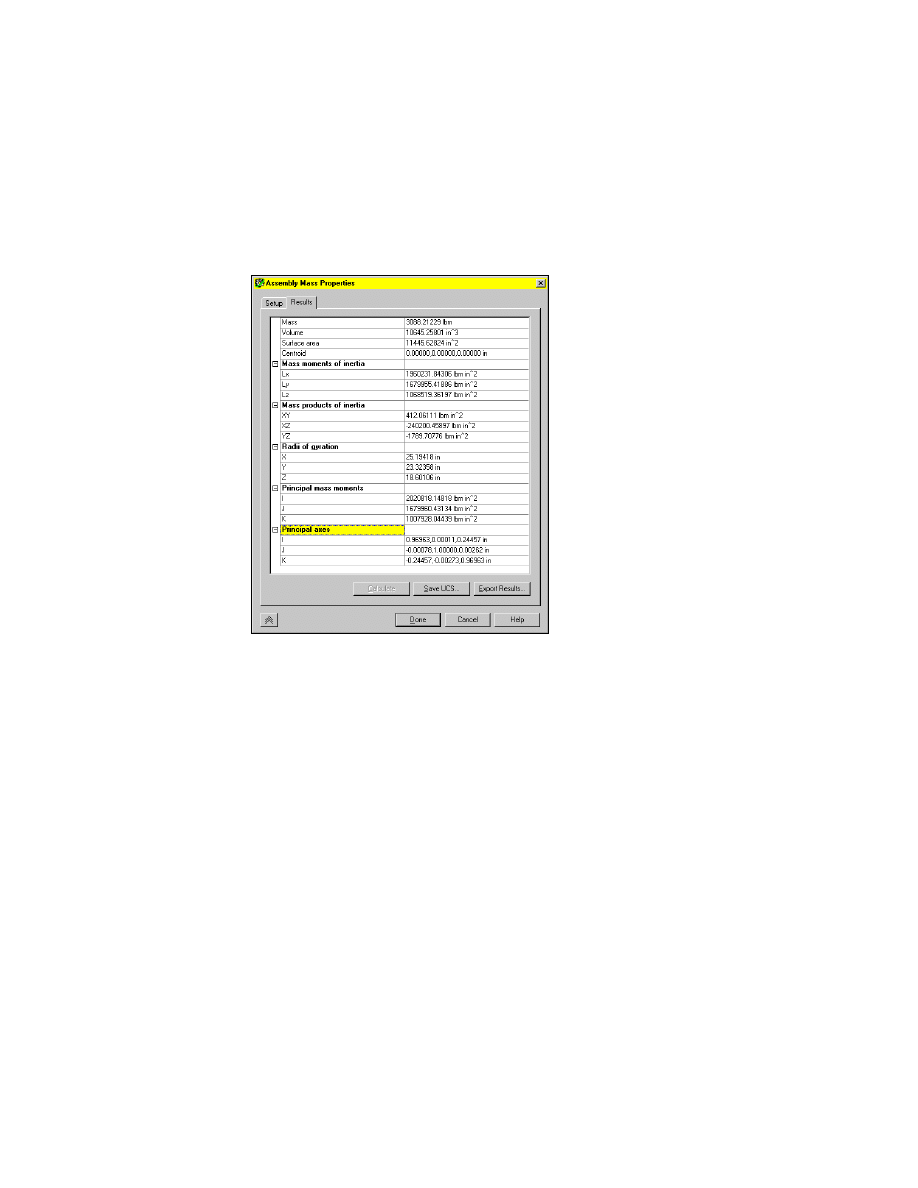
512
|
Chapter 18
Assembling Complex Models
To calculate mass properties
1
In the Mass Properties Dialog Box, select the Results tab. Then select the
Calculate button.
The results are calculated and displayed.
The Calculate button is no longer available because the Setup and Results
fields are in sync. If you change an item on the Setup tab, the results are
cleared and the Calculate button becomes available.
You can use the Insert UCS button to create and insert a user coordinate sys-
tem (UCS) based on a parts or assemblies center of gravity (CG).
2
Choose Export Results.
In the File dialog box, define a file name and save the file.
This report file can be imported by many external programs.
3
Choose Done to close the Assembly Mass Properties dialog box.
Save your file.
Now, you create an exploded view of the assembly.
Reviewing Assembly Models
|
513
Reviewing Assembly Models
Assembly scenes and drawing views are essential for reviewing the assembly
model. For this lesson, you first create an exploded assembly scene, and then
tweak the positions of parts and add assembly trails and annotations.
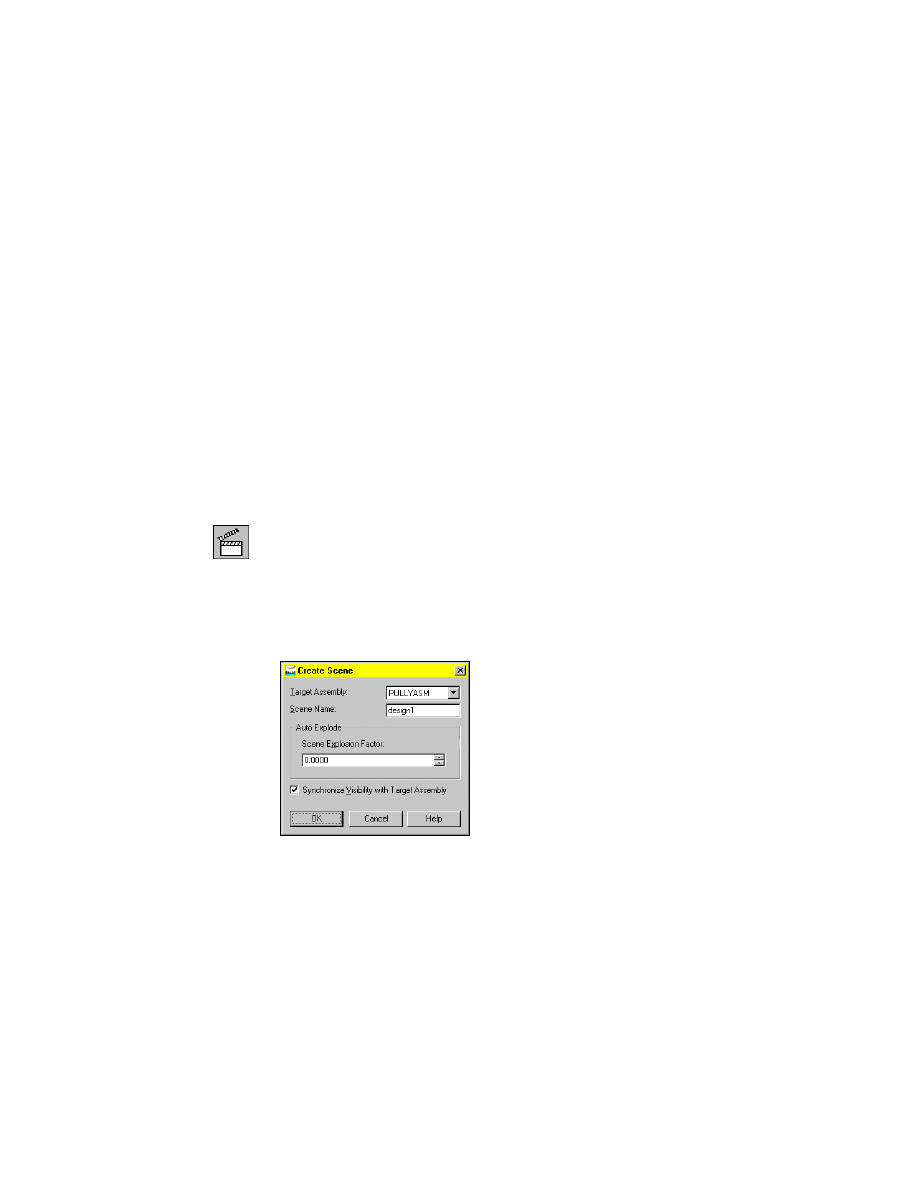
Creating Exploded Assembly Scenes
After assembly constraints have been applied to each part, you can create a
scene (an exploded view of the entire assembly). Multiple scenes can be
created and named. You set an explosion factor to determine the separation
of parts in the scene. If you do not want an exploded view in a scene, set the
explosion factor to 0.
Before you begin, select the Scene tab to switch to Scene mode.
To create an exploded assembly scene
1
Use AMNEW to create a new scene, responding to the prompts.
Context Menu
In the graphics area, right-click and choose New Scene.
In the Create Scene dialog box, specify:
Target Assembly:
PULLYASM
Scene Name:
Enter design1
Scene explosion factor <.0000>:
Specify 0.0000
Synchronize Visibility with Target Assembly:
Select the check box
Choose OK.
514
|
Chapter 18
Assembling Complex Models
The scene, design1, is displayed.
2
Look at the Browser. The names of all parts in the design1 scene are listed.
Next, align the exploded parts in the assembly scene.
Reviewing Assembly Models
|
515
Using Tweaks and Trails in Scenes
In an exploded scene, sometimes parts obscure other parts. You can use tweaks
to change the positions of individual parts and then adjust the positions of the
parts in the design1 scene. Zoom in to magnify the parts to be tweaked.
In the Browser, tweaks are nested under the respective parts. You can select and
multi-select tweaks in the Browser to delete them. When you pause the cursor
over a tweak in the Browser, a tooltip displays the distance factor for the tweak.
NOTE
The grounded part of an assembly or a subassembly cannot be
tweaked. Its position is fixed.
Assembly trails use a continuous or other defined linetype to indicate the
path of the explosion. These trails use assembly constraint information to
visually demonstrate how the assembly design fits together.
To tweak an exploded assembly scene
1
Use
AMTWEAK
to open the Power Manipulator dialog box.
Context Menu
In the graphics area, right-click and choose New Tweak.
Select part/subassembly to tweak:
Specify a point on BUSHING_1 (1)
Enter an option [Next/Accept] <Accept>:
Press
ENTER
The Power Manipulator dialog box is displayed only the first time you create
a new tweak.
1
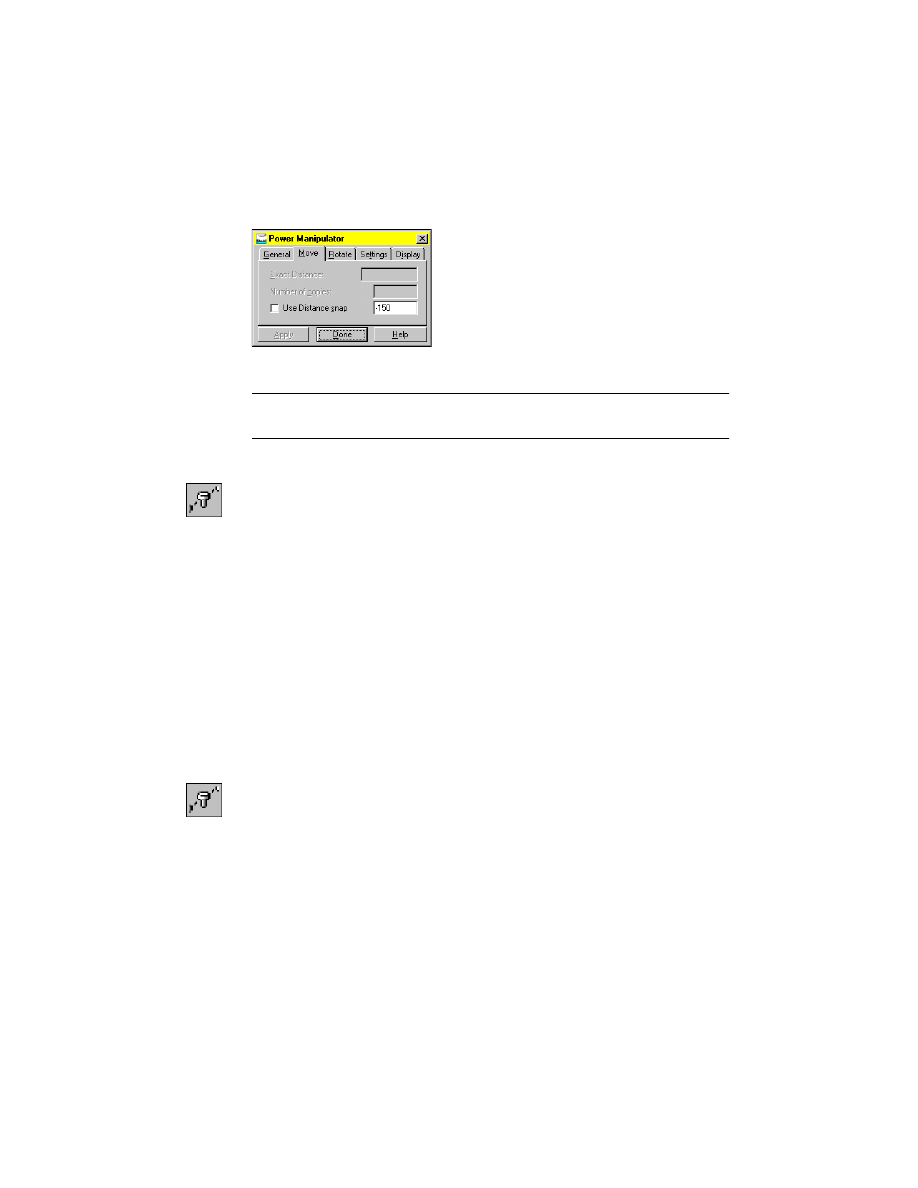
516
|
Chapter 18
Assembling Complex Models
In the Power Manipulator dialog box, on the Move tab, verify that Place
Objects (ALT) is selected.
Choose Done.
NOTE
To access the Power Manipulator dialog box later, right-click the Power
Manipulator symbol on your screen, and select Options.
2
Use
AMTWEAK
to tweak the BUSHING part, responding to the prompts.
Context Menu
In the graphics area, right-click and choose New Tweak.
Select part/subassembly to tweak:
Specify a point on DPULLEY_1 (1)
Enter an option [Next/Accept] <Accept>:
Press
ENTER
This time, the Power Manipulator symbol is displayed on the BUSHING part
you selected.
3
Click the -Z axis on the Power Manipulator symbol, drag away from the
assembly, and click at a distance of -150.
4
Continue on the command line.
Select handle or Geometry
[Undo/UCS/WCS/Select/Options/Pancenter/Type/tRails/X/Y/Z] <Accept>:
Press
ENTER
The BUSHING is moved away from the assembly. In the Browser, a Tweak
icon is displayed.
1
Use
AMTWEAK
to tweak the DPULLEY part, responding to the prompts.
Context Menu
In the graphics area, right-click and choose New Tweak.
Select part/subassembly to tweak:
Specify a point on DPULLEY_1 (1)
Enter an option [Next/Accept] <Accept>:
Press
ENTER
2
Click the -Z axis on the Power Manipulator symbol, drag away from the
assembly, and click at a distance of -70.
Reviewing Assembly Models
|
517
3
Continue on the command line.
Select handle or Geometry
[Undo/UCS/WCS/Select/Options/Pancenter/Type/tRails/X/Y/Z] <Accept>:
Press
ENTER
.
4
Use
AMTWEAK
to tweak the SHAFT part, responding to the prompts.
Context Menu
In the graphics area, right-click and choose New Tweak.
Select part/subassembly to tweak:
Specify a point on SHAFT_1 (1)
Enter an option [Next/Accept] <Accept>:
Press
ENTER
The Power Manipulator symbol is displayed on the SHAFT part.
5
Click the -Z axis on the Power Manipulator symbol, drag away from the
assembly, and click at a distance of -200.
6
Continue on the command line.
Select handle or Geometry
[Undo/UCS/WCS/Select/Options/Pancenter/Type/tRails/X/Y/Z] <Accept>: Enter r
Create Trails? [Yes/No] <No>:
Enter y
[Undo/UCS/WCS/Select/Options/Pancenter/Type/tRails/X/Y/Z] <Accept>:
Press
ENTER
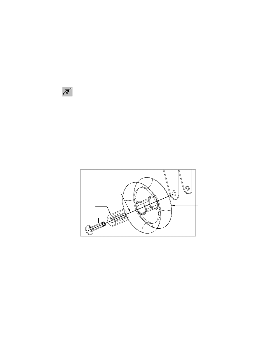
The BUSHING, DPULLEY, and SHAFT part tweaks are displayed with trails.
You can adjust assembly trails.
tweaked
dpulley
tweaked
bushing
tweaked
shaft
assembly trail added
518
|
Chapter 18
Assembling Complex Models
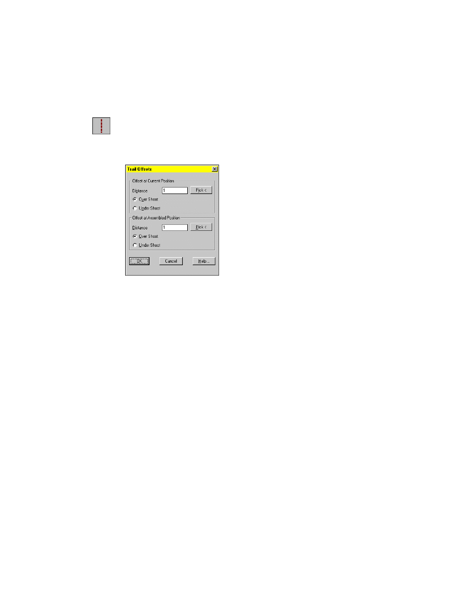
To adjust assembly trails
1
Use
AMTRAIL
to adjust your assembly trails, responding to the prompt.
Command
AMTRAIL
The Trail Offsets dialog box is displayed.
2
Use the options in the Trail Offsets dialog box, to adjust over shoots and
undershoots for your trails.
Choose OK to apply your selections.
Next, create an assembly drawing view.
Creating Assembly Drawing Views
An assembly drawing view shows a 2D representation of the 3D assembly.
You use the base part for a base view. Then you create an isometric view of
the entire assembly model. Drawing views are automatically updated when
you change a part or subassembly.
Before you begin, select the Drawing tab to switch to Drawing mode.
Reviewing Assembly Models
|
519
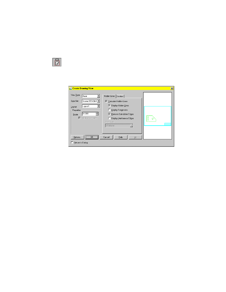
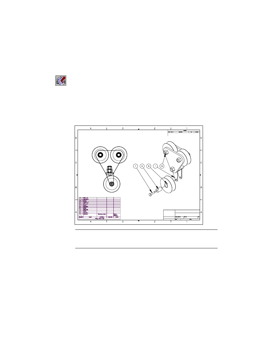
To create a drawing view
1
Use AMDWGVIEW to create a new drawing view.
Context Menu
In the graphics area, right-click and choose New View.
2
In the Create Drawing View dialog box, specify:
Type:
Base
Data Set:
Scene: DESIGN1
Scale:
Enter .03 (or .75 mm)
Choose OK.
3
Respond to the prompts as follows:
Select planar face, work plane or [Ucs/View/worldXy/worldYz/worldZx]:
Enter z
Select work axis, straight edge or [worldX/worldY/worldZ]:
Enter x
Adjust orientation [Flip/Rotate] <accept>
Enter r until the UCS icon is upright
Adjust orientation [Flip/Rotate] <accept>:
Press
ENTER
Specify location of base view:
Specify a point in the left of the title block
Specify location of base view:
Press
ENTER
520
|
Chapter 18
Assembling Complex Models
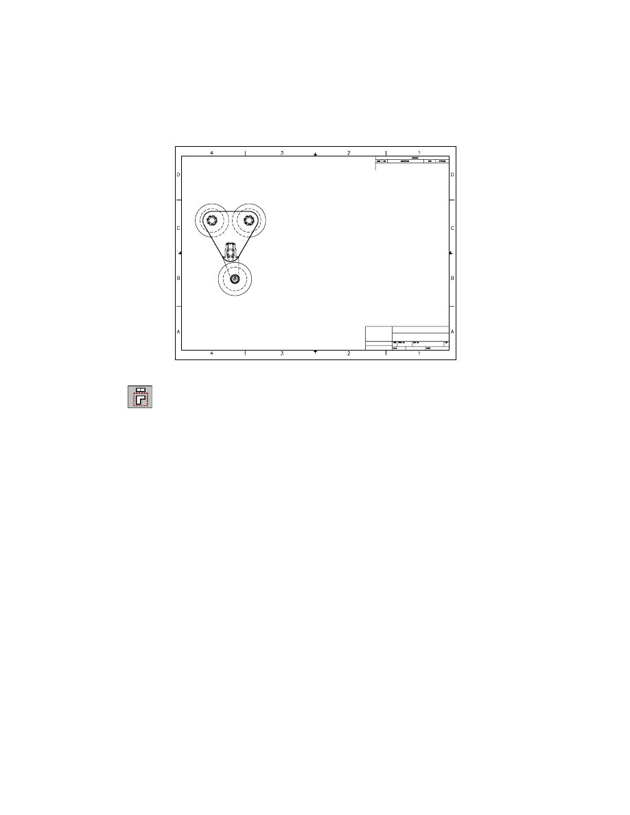
The base assembly drawing view is displayed.
4
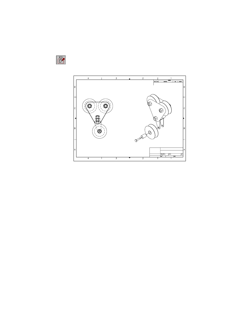
Create an isometric view of the assembly.
Context Menu
In the graphics area, right-click and choose New View.
In the Create Drawing View dialog box, specify:
View Type:
Iso
Scale:
Enter 1
Relative to Parent:
Select the check box
Choose OK.
5
Respond to the prompts as follows:
Select parent view:
Select the base view
Specify location for isometric view:
Specify a point to the right of the base view
Specify location for isometric view:
Press
ENTER
An isometric view of the assembly is displayed.
Reviewing Assembly Models
|
521
6
Use
AMMOVEVIEW
to align the views, responding to the prompts.
Context Menu
In the graphics area, right-click and choose Move View.
Select view to move:
Select the isometric view
Specify new view location or [Layout]:
Align the views and press
ENTER
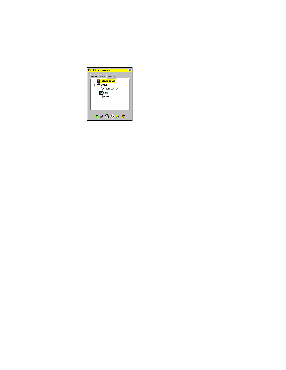
Examine the Browser. The isometric view is listed under the base view.
Now, create a BOM database, and add a parts list and associative balloon callouts.
522
|
Chapter 18
Assembling Complex Models
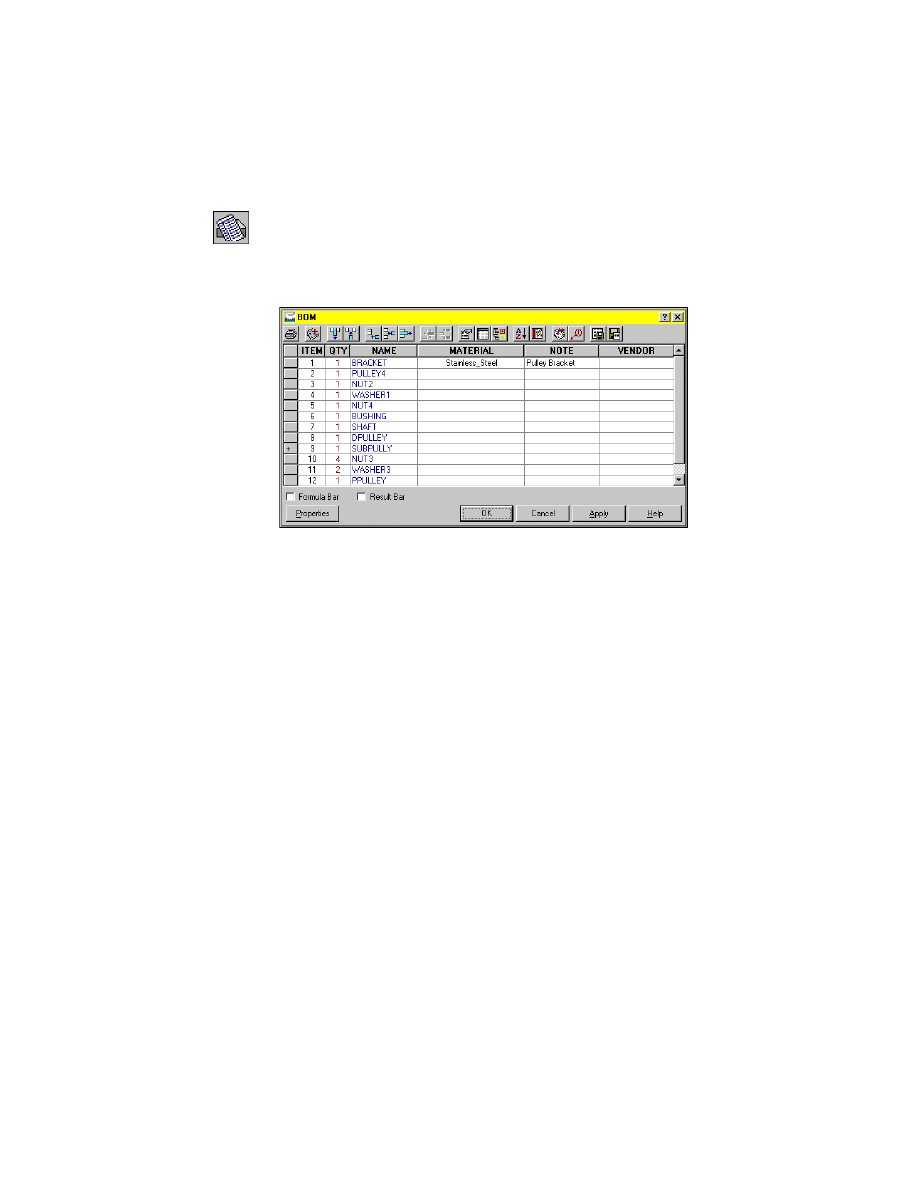
Creating Bills of Material
After you have assembled your parts, you can create a bill of material (BOM)
database. This database contains a list of attributes assigned to each part. The
attributes store information such as manufacturer, description, and vendor
part number.
The attributes are contained in part references that are assigned to each part.
Part references can also be created to reference other geometry in your draw-
ing, such as surfaces. The geometry can then be included in a parts list.
The BOM database counts the number of instances in an assembly and tallies
instances for each part. In the BOM table, defined columns can be edited,
added, deleted, moved, and sorted.
By accessing the information in the BOM database, you can add balloons and
insert parts lists into your drawing. You can edit part references, balloons,
and parts lists. The BOM database is automatically updated.
Because the BOM database is fully parametric, any changes to it update the
information stored in balloons, part references, and parts lists.
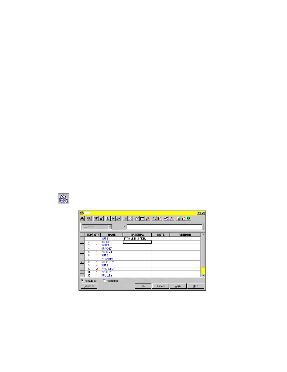
To create a BOM database
1
Use
AMBOM
to create the BOM database.
Command
AMBOM
In the BOM dialog box, review the parts in the database.
Creating Bills of Material
|
523
Notice the SUBPULLY definition in the list of parts. The plus sign in front of
it indicates that it is a subassembly.
2
Click the plus sign in front of SUBPULLY.
The BOM database now lists all the parts in the assembly, including those in
the subassembly.
Choose OK to exit the BOM dialog box.
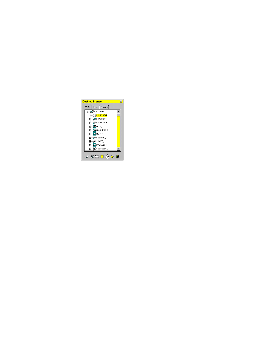
3
Select the Model tab in the browser. A BOM icon is located under PULLYASM.
By default, the BOM takes the same name as the assembly file. You can
change this setting by editing the name of the BOM directly in the Browser.
To edit the name of a BOM
1
Using the Browser, rename the BOM database.
Browser
Right-click the BOM icon and choose Rename.
2
Change the name to BOM_1.
Customizing BOM Databases
Mechanical Desktop provides symbol standards for major drafting conven-
tions, including ANSI, BSI, CSN, DIN, GB, ISO, and JIS. By modifying the
symbol standards, you can control the way symbols, balloons, and parts lists
are displayed in the drawing, when you create them.
Next, modify the symbol standards to control the number of columns used
in the parts list and the name of one of the columns.
524
|
Chapter 18
Assembling Complex Models
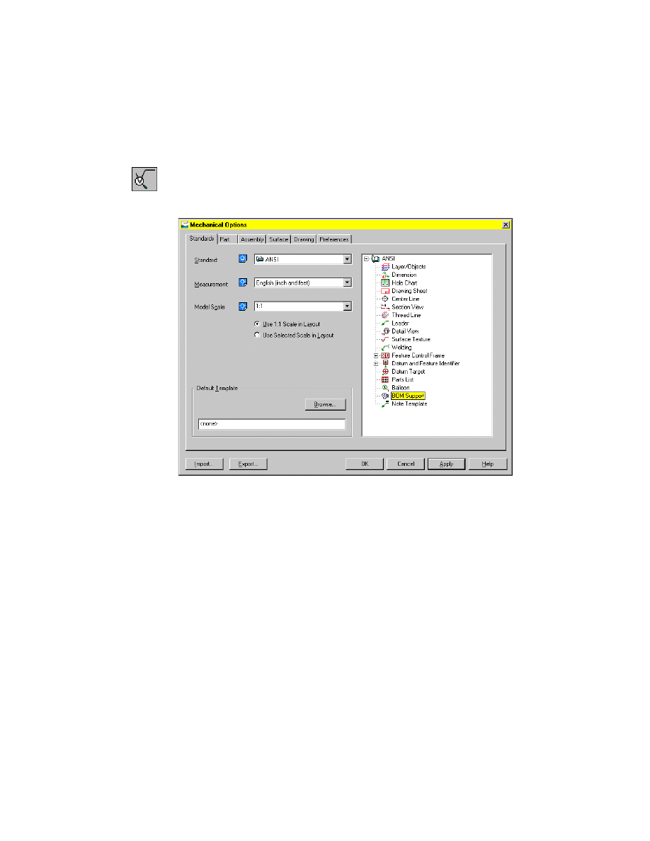
To modify symbol standards
1
Use
AMOPTIONS
to access the Mechanical Desktop symbol standards.
Command
AMOPTIONS
In the Mechanical Options dialog box, expand the hierarchy of ANSI, and
double-click the icon in front of BOM Support.
2
In the BOM Properties for ANSI dialog box, in Columns select Material and
specify:
Caption Alignment:
Select the Center Align Text icon
Data Alignment:
Select the Center Align Text icon
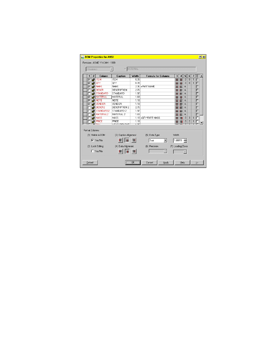
Creating Bills of Material
|
525
Choose Apply, then OK.
The Mechanical Options dialog box is still open.
3
Choose OK to close the Symbol Standards dialog box.
Save your file.
Working with Part References
When you create a BOM database, each part in the assembly is assigned a part
reference. A part reference is an attributed block that can be modified to
include any information you want to attach to the part. That information is
used by the BOM database and included in the parts lists you generate.
Before you begin, in the Browser, select the Drawing tab to switch to Drawing
mode.
526
|
Chapter 18
Assembling Complex Models
To edit a part reference
1
Use
AMPARTREFEDIT
to edit a part reference, responding to the prompt.
Context Menu
In the graphics area, right-click and choose Annotate
Menu ➤ Parts List ➤ Part Reference Edit.
Select pick object:
Select the part reference for BRACKET
(1)
2
In the Part Ref Attributes dialog box, double-click in the Name field and enter
Pulley Bracket.
Choose OK.
1
Creating Bills of Material
|
527
3
Use
AMBOM
to display the BOM database.
Context Menu
In the graphics area, right-click and choose Parts List ➤
BOM Database.
Bom table [Delete/Edit] <Edit>:
Press
ENTER
Notice that Pulley Bracket is now listed under Note for BRACKET.
Choose OK to exit the BOM dialog box.
Next, add balloon callouts to the isometric view.
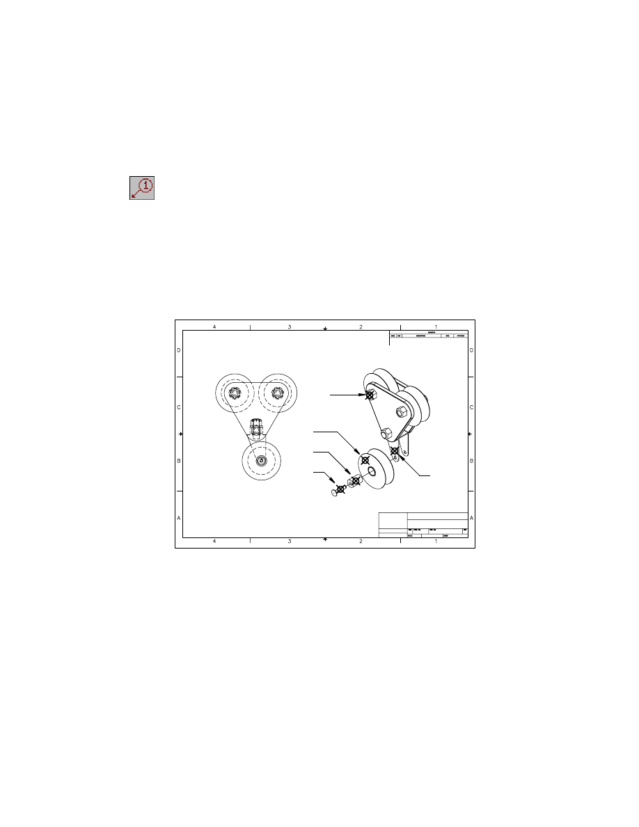
Adding Balloons
Balloons are used to reference parts in your drawing to a parts list. They con-
tain the same information as the part reference they are attached to. You can
edit that data by selecting balloons. Changes made to the data associated
with a balloon are reflected in the BOM database and the parts list.
You can control the size and appearance of balloons, using the Symbol Stan-
dards dialog box.
528
To place a balloon callout
1
Use
AMBALLOON
to create balloon callouts for BRACKET, DPULLEY, BUSH-
ING, SHAFT, and NUT3, responding to the prompts.
Desktop Menu
Choose Annotate ➤ Parts List ➤ Balloon.
Select part/assembly or [auTo/autoAll/Collect/Manual/One/ Renumber/
rEorganize]:
Enter T
Align [Angle/Standalone/Horizontal/Vertical] <Vertical>: Press
ENTER
Select pick object:
Select the part reference for BRACKET (1)
Select pick object:
Select the part reference for DPULLEY (2)
Select pick object:
Select the part reference for BUSHING (3)
Select pick object:
Select the part reference for SHAFT (4)
Select pick object:
Select the part reference for NUT3 (5)
The objects are aligned after you pick them.
2
3
4
1
5
Creating Bills of Material
|
529
Continue on the command line:
Select pick object:
Press
ENTER
Align Standalone/Horizontal/<Vertical>:
Specify a point between the two drawing views
Next, place the parts list in the drawing.
Placing Parts Lists
A parts list is an associative block of information about your assembly. It dis-
plays information about the parts, according to the settings specified in the
BOM database. Because it is parametric, any changes you make to the BOM
database or symbol standards are automatically reflected in the parts list.
530
|
Chapter 18
Assembling Complex Models
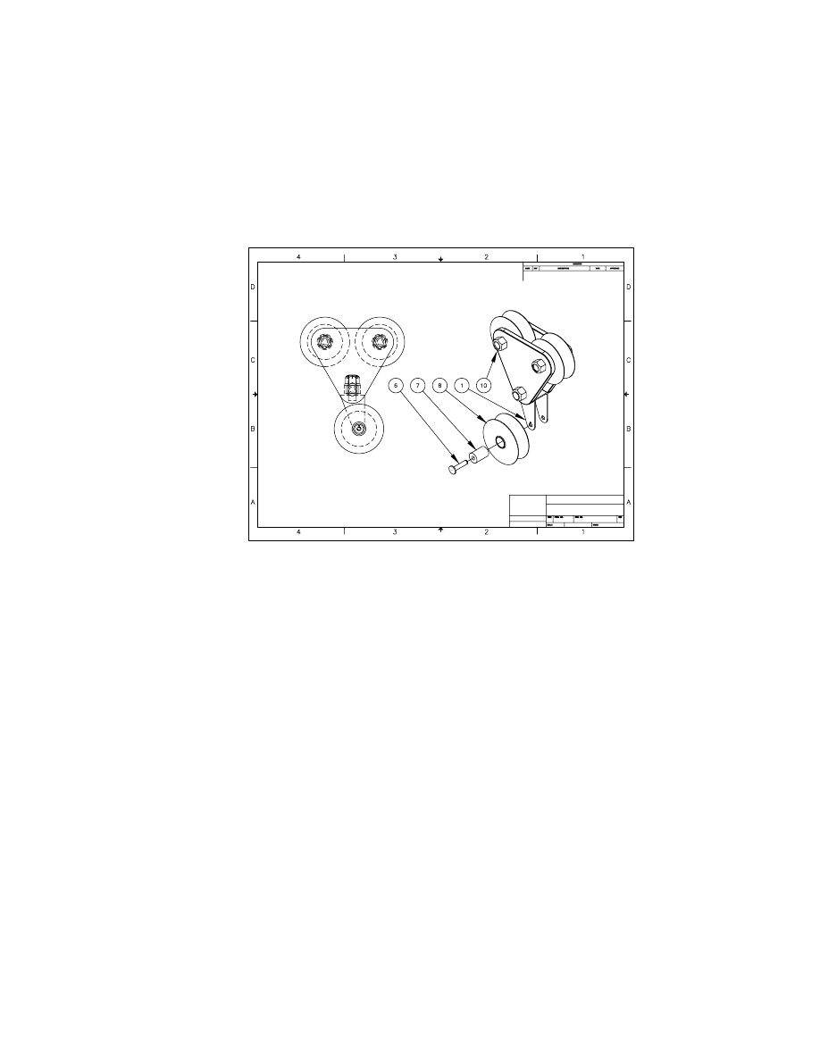
To place a parts list
1
Use
AMPARTLIST
to place the parts list under the base view of your assembly,
responding to the prompts.
Context Menu
In the graphics area, right-click and choose Parts List ➤
Part List.
The Parts List dialog box is displayed.
2
In the Parts List dialog box, in Title, enter the new name Pulley Parts List.
3
Choose Apply, then choose OK.
Specify location:
Specify a point under the base view
The parts list is placed in the drawing.
NOTE
You may need to move the drawing views to make room for the parts
list. Place the parts list first, and then move the views as needed. Because the bal-
loons are associated with the views, they will also move.
Finishing Drawings for Plotting
|
531
When the parts list is created, a parts list icon is displayed in the Browser.
Save your file.
Finishing Drawings for Plotting
Now that the assembly has been documented, plot the drawing.
Paper drawings are useful for reviewing the entire assembly to make sure that
the design is feasible and can be manufactured. The Parts List on the assem-
bly drawing provides information about the parts needed to manufacture the
assembly. If you wish, add more reference dimensions, fill in the title block,
and add some notes to your drawing before you plot.
This tutorial has demonstrated the flexibility of using subassemblies to create
complex models. Even a complex assembly can be easily modified and doc-
umented, if it is truly a parametric assembly.

532
Wyszukiwarka
Podobne podstrony:
Modeling complex systems of systems with Phantom System Models
3.8.2 Lab Complete Assembly
3 8 2 Lab Complete Assembly
lecture3 complexity introduction
L 3 Complex functions and Polynomials
assembler
Assembler ENG
Assembly Language for Kids Commodore 64 Addendum
Complexes
Akumulator do BOMBARDIER ROTAX All models Yeti BR All models
LES PRONOMS COMPLEMENT
P000718 A Eng Vertical shaft assembly
M001882 B Eng Lower assembly
Complete Timeline of Darkest Powers Stories 2011 04 13
Ch18 Stress Calculations
więcej podobnych podstron