
White Paper
Gigabit
Ethernet and ATM
A Technology Perspective
Bursty, high-bandwidth applications are driving
the need for similarly high-bandwidth campus
backbone infrastructures. Today, there are two choices
for the high-speed campus backbone: ATM or Gigabit
Ethernet. For many reasons, business and technical,
Gigabit Ethernet is selected as the technology of choice.
This paper briefly presents, from a technical perspective,
why Gigabit Ethernet is favored for most enterprise LANs.

In the past, most campuses use shared-media backbones
— such as 16/32 Mbps Token-Ring and 100 Mbps FDDI —
that are only slightly higher in speed than the LANs
and end stations they interconnect. This has caused
severe congestion in the campus backbones when these
backbones interconnect a number of access LANs.
Gigabit Ethernet and ATM: A Technology Perspective White Paper
2
A high capacity, high performance, and highly resilient
backbone is needed-one that can be scaled as end stations
grow in number or demand more bandwidth. Also
needed is the ability to support differentiated service
levels (Quality of Service or QoS), so that high priority,
time-sensitive, and mission-critical applications can
share the same network infrastructure as those that
require only best-effort service.

Gigabit Ethernet and ATM: A Technology Perspective White Paper
3
Interface, and Multiprotocol over ATM).
This additional complexity is required in
order to adapt ATM to the connectionless,
frame-based world of the campus LAN.
Meanwhile, the very successful Fast
Ethernet experience spurred the development
of Gigabit Ethernet standards. Within
two years of their conception (June
1996), Gigabit Ethernet over fiber
(1000BASE-X) and copper (1000BASE-T)
standards were approved, developed, and
in operation. Gigabit Ethernet not only
provides a massive scaling of bandwidth
to 1000 Mbps (1 Gbps), but also shares a
natural affinity with the vast installed base
of Ethernet and Fast Ethernet campus
LANs running IP applications.
Enhanced by additional protocols already
common to Ethernet (such as IEEE
802.1Q Virtual LAN tagging, IEEE
802.1p prioritization, IETF
Differentiated Services, and Common
Open Policy Services), Gigabit Ethernet is
now able to provide the differential qualities
of service that previously only ATM could
provide. One key difference with Gigabit
Ethernet is that additional functionality
can be incrementally added in a
non-disruptive way as required, compared
with the rather revolutionary approach of
ATM. Further developments in bandwidth
and distance scalability will see 10 Gbps
Ethernet over local (10G-BASE-T) and
wide area (10G-BASE-WX) networks.
Thus, the promise of end-to-end seamless
integration, once only the province of
ATM, will be possible with Ethernet
and all its derivations.
Today, there are two technology choices
for the high-speed campus backbone:
ATM and Gigabit Ethernet. While both
seek to provide high bandwidth and
differentiated QoS within enterprise
LANs, these are very different technologies.
Which is a “better” technology is no
longer a subject of heated industry debate
— Gigabit Ethernet is an appropriate
choice for most campus backbones.
Many business users have chosen Gigabit
Ethernet as the backbone technology
for their campus networks. An Infonetics
Research survey (March 1999) records
that 91 percent of respondents believe
that Gigabit Ethernet is suitable for LAN
backbone connection, compared with 66
percent for ATM. ATM continues to be a
good option where its unique, rich, and
complex functionality can be exploited
by its deployment, most commonly in
metropolitan and wide area networks.
Whether Gigabit Ethernet or ATM
is deployed as the campus backbone
technology of choice, the ultimate
decision is one of economics and sound
business sense, rather than pure technical
considerations.
The next two sections provide a brief
description of each technology.
Asynchronous Transfer
Mode (ATM)
Asynchronous Transfer Mode (ATM)
has been used as a campus backbone
technology since its introduction in the
early 1990s. ATM is specifically designed
to transport multiple traffic types —
data, voice and video, real-time or
non-real-time — with inherent QoS
for each traffic category.
To enable this and other capabilities,
additional functions and protocols are
added to the basic ATM technology.
Private Network Node Interface (PNNI)
provides OSPF-like functions to signal
and route QoS requests through a
hierarchical ATM network. Multiprotocol
Until recently, Asynchronous Transfer
Mode (ATM) was the only switching
technology able to deliver high capacity
and scalable bandwidth, with the promise
of end-to-end Quality of Service. ATM
offered seamless integration from the
desktop, across the campus, and over the
metropolitan/wide area network. It was
thought that users would massively
deploy connection-oriented, cell-based
ATM to the desktop to enable new native
ATM applications to leverage ATM’s rich
functionality (such as QoS). However,
this did not come to pass. The Internet
Protocol (IP), aided and abetted by the
exploding growth of the Internet, rode
roughshod over ATM deployment and
marched relentlessly to world dominance.
When no other gigabit technology existed,
ATM provided much needed relief as a
high bandwidth backbone to interconnect
numerous connectionless, frame-based
campus LANs. But with the massive
proliferation of IP applications, new
native ATM applications did not appear.
Even 25 Mbps and 155 Mbps ATM
to the desktop did not appeal to the
vast majority of users, because of their
complexity, small bandwidth increase,
and high costs when compared with the
very simple and inexpensive 100 Mbps
Fast Ethernet.
On the other hand, Fast Ethernet, with its
auto-sensing, auto-negotiation capabilities,
integrated seamlessly with the millions
of installed 10 Mbps Ethernet clients
and servers. Although relatively simple
and elegant in concept, the actual
implementation of ATM is complicated
by a multitude of protocol standards
and specifications (for instance, LAN
Emulation, Private Network Node

over ATM (MPOA) allows the establish-
ment of short-cut routes between
communicating end systems on different
subnets, bypassing the performance
bottlenecks of intervening routers. There
have been and continue to be enhancements
in the areas of physical connectivity,
bandwidth scalability, signaling, routing
and addressing, security, and management.
While rich in features, this functionality
has come with a fairly heavy price tag in
complexity and cost. To provide backbone
connectivity for today’s legacy access
networks, ATM — a connection-oriented
technology — has to emulate capabilities
inherently available in the predominantly
connectionless Ethernet LANs, including
broadcast, multicast, and unicast
transmissions. ATM must also manipulate
the predominantly frame-based traffic on
these LANs, segmenting all frames into cells
prior to transport, and then reassembling
cells into frames prior to final delivery.
Many of the complexity and interoperability
issues are the result of this LAN
Emulation, as well as the need to provide
resiliency in these emulated LANs. There
are many components required to make
this workable; these include the LAN
Emulation Configuration Server(s),
LAN Emulation Servers, Broadcast and
Unknown Servers, Selective Multicast
Servers, Server Cache Synchronization
Protocol, LAN Emulation User Network
Interface, LAN Emulation Network-
Network Interface, and a multitude of
additional protocols, signaling controls,
and connections (point-to-point, point-
to-multipoint, multipoint-to-point, and
multipoint-to-multipoint).
Until recently, ATM was the only
technology able to promise the benefits
of QoS from the desktop, across the LAN
and campus, and right across the world.
However, the deployment of ATM to the
desktop, or even in the campus backbone
LANs, has not been as widespread as
predicted. Nor have there been many
native applications available or able to
benefit from the inherent QoS capabilities
provided by an end-to-end ATM solution.
Thus, the benefits of end-to-end QoS
have been more imagined than realized.
Gigabit Ethernet as the campus backbone
technology of choice is now surpassing
ATM. This is due to the complexity
and the much higher pricing of ATM
components such as network interface
cards, switches, system software,
management software, troubleshooting
tools, and staff skill sets. There are also
interoperability issues, and a lack of
suitable exploiters of ATM technology.
Gigabit Ethernet
Today, Gigabit Ethernet is a very viable
and attractive solution as a campus
backbone LAN infrastructure. Although
relatively new, Gigabit Ethernet is derived
from a simple technology, and a large and
well-tested Ethernet and Fast Ethernet
installed base. Since its introduction,
Gigabit Ethernet has been vigorously
adopted as a campus backbone technology,
with possible use as a high-capacity
connection for high-performance servers
and workstations to the backbone switches.
The main reason for this success is that
Gigabit Ethernet provides the functionality
that meets today’s immediate needs at an
affordable price, without undue complexity
and cost. Gigabit Ethernet is complemented
by a superset of functions and capabilities
that can be added as needed, with the
promise of further functional enhancements
and bandwidth scalability (for example,
IEEE 802.3ad Link Aggregation, and 10
Gbps Ethernet) in the near future. Thus,
Gigabit Ethernet provides a simple
scaling-up in bandwidth from the 10/100
Mbps Ethernet and Fast Ethernet LANs
that are already massively deployed.
Simply put, Gigabit Ethernet is Ethernet,
but 100 times faster!
Since Gigabit Ethernet uses the same
frame format as today’s legacy installed
LANs, it does not need the segmentation
and reassembly function that ATM
requires to provide cell-to-frame and
frame-to-cell transitions. As a connection-
less technology, Gigabit Ethernet does not
require the added complexity of signaling
and control protocols and connections
that ATM requires. Finally, because QoS-
capable desktops are not readily available,
Gigabit Ethernet is no less deficient in
providing QoS. New methods have been
developed to incrementally deliver QoS
and other needed capabilities that lend
themselves to much more pragmatic and
cost-effective adoption and deployment.
To complement the high-bandwidth
capacity of Gigabit Ethernet as a campus
backbone technology, higher-layer functions
and protocols are available, or are being
defined by standards bodies such as the
Institute of Electrical and Electronics
Engineers (IEEE) and the Internet
Gigabit Ethernet and ATM: A Technology Perspective White Paper
4

Engineering Task Force (IETF). Many of
these capabilities recognize the desire for
convergence upon the ubiquitous Internet
Protocol (IP). IP applications and transport
protocols are being enhanced or developed
to address the needs of high speed, multi-
media networking that benefit Gigabit
Ethernet. The Differentiated Services
(DiffServ) standard provides differential
QoS that can be deployed from the
Ethernet and Fast Ethernet desktops
across the Gigabit Ethernet campus
backbones. The use of IEEE 802.1Q
VLAN Tagging and 802.1p User Priority
settings allow different traffic types to
be accorded the appropriate forwarding
priority and service.
When combined with policy-enabled
networks, DiffServ provides powerful,
secure, and flexible QoS capabilities for
Gigabit Ethernet campus LANs by using
protocols such as Common Open Policy
Services (COPS), Lightweight Directory
Access Protocol (LDAP), Dynamic Host
Configuration Protocol (DHCP), and
Domain Name System (DNS). Further
developments, such as Resource
Reservation Protocol, multicasting,
real-time multimedia, audio and video
transport, and IP telephony, will add
functionality to a Gigabit Ethernet campus,
using a gradual and manageable approach
when users need these functions.
There are major technical differences
between Gigabit Ethernet and ATM. A
companion white paper, Gigabit Ethernet
and ATM: A Business Perspective, provides a
comparative view of the two technologies
from a managerial perspective.
Gigabit Ethernet and ATM: A Technology Perspective White Paper
5
Technological Aspects
Aspects of a technology are important
because they must meet some minimum
requirements to be acceptable to users.
Value-added capabilities will be used
where desirable or affordable. If these
additional capabilities are not used,
whether for reasons of complexity or lack
of “exploiters” of those capabilities, then
users are paying for them for no reason
(a common example is that many of the
advanced features of a VCR are rarely
exploited by most users). If features are
too expensive, relative to the benefits that
can be derived, then the technology is
not likely to find widespread acceptance.
Technology choices are ultimately
business decisions.
The fundamental requirements for LAN
campus networks are very much different
from those of the WAN. It is thus
necessary to identify the minimum
requirements of a network, as well as
the value-added capabilities that are
“nice to have”.
In the sections that follow, various terms
are used with the following meanings:
• “Ethernet” is used to refer to all current
variations of the Ethernet technology:
traditional 10 Mbps Ethernet, 100
Mbps Fast Ethernet, and 1000 Mbps
Gigabit Ethernet.
• “Frame” and “packet” are used
interchangeably, although this is not
absolutely correct from a technical
purist point of view.
Quality of Service
Until recently, Quality of Service (QoS)
was a key differentiator between ATM
and Gigabit Ethernet. ATM was the only
technology that promised QoS for voice,
video, and data traffic. The Internet
Engineering Task Force (IETF) and
various vendors have since developed
protocol specifications and standards that
enhance the frame-switched world with
QoS and QoS-like capabilities. These
efforts are accelerating and, in certain
cases, have evolved for use in both the
ATM and frame-based worlds.
The difference between ATM and Gigabit
Ethernet in the delivery of QoS is that
ATM is connection-oriented, whereas
Ethernet is connectionless. With ATM,
QoS is requested via signaling before
communication can begin. The connection
is only accepted if it is without detriment
to existing connections (especially for
reserved bandwidth applications).
Network resources are then reserved as
required, and the accepted QoS service is
guaranteed to be delivered “end-to-end.”
By contrast, QoS for Ethernet is mainly
delivered hop-by-hop, with standards
in progress for signaling, connection
admission control, and resource reservation.

ATM QoS
From its inception, ATM has been
designed with QoS for voice, video
and data applications. Each of these
has different timing bounds, delay,
delay variation sensitivities (jitter),
and bandwidth requirements.
In ATM, QoS has very specific meanings
that are the subject of ATM Forum and
other standards specifications. Defined at
the ATM layer (OSI Layer 2), the service
architecture provides five categories of
services that relate traffic characteristics
and QoS requirements to network behavior:
•
CBR:
Constant Bit Rate, for applications
that are sensitive to delay and delay
variations, and need a fixed but
continuously available amount of
bandwidth for the duration of a
connection. The amount of bandwidth
required is characterized by the
Peak Cell Rate. An example of this
is circuit emulation.
•
rt-VBR:
Real-time Variable Bit Rate, for
applications that need varying amounts
of bandwidth with tightly regulated
delay and delay variation, and whose
traffic is bursty in nature. The amount
of bandwidth is characterized by the
Peak Cell Rate and Sustainable Cell
Rate; burstiness is defined by the
Maximum Burst Size. Example
applications include real-time voice
and video conferencing.
•
nrt-VBR:
Non-real-time Variable Bit
Rate, for applications with similar
needs as rt-VBR, requiring low cell loss,
varying amounts of bandwidth, and
with no critical delay and delay
variation requirements. Example
applications include non-real-time
voice and video.
•
ABR:
Available Bit Rate, for applications
requiring low cell loss, guaranteed
minimum and maximum bandwidths,
and with no critical delay or delay
variation requirements. The minimum
and maximum bandwidths are
characterized by the Minimum Cell
Rate and Peak Cell Rate respectively.
•
UBR:
Unspecified Bit Rate, for
applications that can use the network
on a best-effort basis, with no service
guarantees for cell loss, delay and delay
variations. Example applications are
e-mail and file transfer.
Depending on the QoS requested, ATM
provides a specific level of service. At
one extreme, ATM provides a best-effort
service for the lowest QoS (UBR), with
no bandwidth reserved for the traffic.
At the other extreme, ATM provides a
guaranteed level of service for the higher
QoS (that is, CBR and VBR) traffic.
Between these extremes, ABR is able to
use whatever bandwidth is available with
proper traffic management and controls.
Because ATM is connection-oriented,
requests for a particular QoS, admission
control, and resource allocation are an
integral part of the call signaling and
connection setup process. The call is
admitted and the connection established
between communicating end systems
only if the resources exist to meet a
requested QoS, without jeopardizing
services to already established connections.
Once established, traffic from the end
systems are policed and shaped for
conformance with the agreed traffic
contract. Flow and congestion are
managed in order to ensure the proper
QoS delivery.
Gigabit Ethernet QoS
One simple strategy for solving the
backbone congestion problem is to over-
provision bandwidth in the backbone.
This is especially attractive if the initial
investment is relatively inexpensive and
the ongoing maintenance is virtually
‘costless’ during its operational life.
Gigabit Ethernet is an enabler of just such
a strategy in the LAN. Gigabit Ethernet,
and soon 10-Gigabit Ethernet, will
provide all the bandwidth that is ever
needed for many application types,
eliminating the need for complex QoS
schemes in many environments. However,
some applications are bursty in nature
and will consume all available bandwidth,
to the detriment of other applications that
may have time-critical requirements. The
solution is to provide a priority mechanism
that ensures bandwidth, buffer space,
and processor power are allocated to the
different types of traffic.
With Gigabit Ethernet, QoS has a broader
interpretation than with ATM. But it
is just as able — albeit with different
mechanisms — to meet the requirements
of voice, video and data applications.
In general, Ethernet QoS is delivered
at a high layer of the OSI model. Frames
are typically classified individually by a
filtering scheme. Different priorities are
assigned to each class of traffic, either
explicitly by means of priority bit settings
in the frame header, or implicitly in the
Gigabit Ethernet and ATM: A Technology Perspective White Paper
6

Gigabit Ethernet and ATM: A Technology Perspective White Paper
7
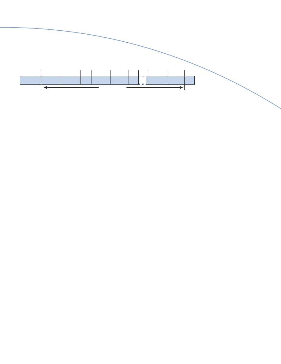
Figure 1: Differentiated Services Field (RFC 2474).
priority level of the queue or VLAN to
which they are assigned. Resources are
then provided in a preferentially prioritized
(unequal or unfair) way to service the
queues. In this manner, QoS is delivered
by providing differential services to
the differentiated traffic through this
mechanism of classification, priority
setting, prioritized queue assignment,
and prioritized queue servicing. (For
further information on QoS in Frame-
Switched Networks, see WP3510-A/5-99,
a Nortel Networks white paper available
on the Web at www.nortelnetworks.com.)
Differentiated Services
Chief among the mechanisms available
for Ethernet QoS is Differentiated
Services (DiffServ). The IETF DiffServ
Working Group proposed DiffServ
as a simple means to provide scalable
differentiated services in an IP network.
DiffServ redefines the IP Precedence/Type
of Service field in the IPv4 header and
the Traffic Class field in the IPv6 header
as the new DS Field (see Figure 1). An IP
packet’s DS Field is then marked with a
specific bit pattern, so the packet will
receive the desired differentiated service
(that is, the desired forwarding priority),
also known as per-hop behavior (PHB),
at each network node along the path
from source to destination.
To provide a common use and interpreta-
tion of the possible DSCP bit patterns,
RFC 2474 and RFC 2475 define the
architecture, format, and general use
of these bits within the DSCP Field.
These definitions are required in order
to guarantee the consistency of expected
service when a packet crosses from one
network’s administrative domain to
another, or for multi-vendor interoperability.
The Working Group also standardized the
following specific per-hop behaviors and
recommended bit patterns (also known as
code points or DSCPs) of the DS Field
for each PHB:
• Expedited Forwarding (EF-PHB),
sometimes described as Premium
Service, uses a DSCP of b’101110’.
The EF-PHB provides the equivalent
service of a low loss, low latency, low
jitter, assured bandwidth point-to-
point connection (a virtual leased line).
EF-PHB frames are assigned to a high
priority queue where the arrival rate of
frames at a node is shaped to be always
less than the configured departure rate
at that node.
• Assured Forwarding (AF-PHB) uses
12 DSCPs to identify four forwarding
classes, each with three levels of drop
precedence (12 PHBs). Frames are
assigned by the user to the different
classes and drop precedence depending
on the desired degree of assured —
but not guaranteed — delivery. When
allocated resources (buffers and band-
width) are insufficient to meet demand,
frames with the high drop precedence are
discarded first. If resources are still
restricted, medium precedence frames
are discarded next, and low precedence
frames are dropped only in the most
extreme lack of resource conditions.
• A recommended Default PHB with
a DSCP of b’000000’ (six zeros) that
equates to today’s best-effort service
when no explicit DS marking exists.
In essence, DiffServ operates as follows:
• Each frame entering a network is
analyzed and classified to determine
the appropriate service desired by the
application.
• Once classified, the frame is marked in
the DS field with the assigned DSCP
value to indicate the appropriate PHB.
Within the core of the network, frames
are forwarded according to the PHB
indicated.
• Analysis, classification, marking,
policing, and shaping operations need
only be carried out at the host or
network boundary node. Intervening
nodes need only examine the short
fixed length DS Field to determine the
appropriate PHB to be given to the
frame. This architecture is the key to
DiffServ scalability. In contrast, other
models such as RSVP/Integrated
Services are severely limited by signaling,
application flow, and forwarding state
maintenance at each and every node
along the path.
Byte
Bit 1
2
3 4
5
6
7
8
1
IP Version
IP Header Length
2
Differentiated Services Code Point (DSCP)
Currently Unused
3-20
(Remainder of IP Header)
• Policies govern how frames are marked
and traffic conditioned upon entry
to the network; they also govern the
allocation of network resources to the
traffic streams, and how the traffic is
forwarded within that network.
DiffServ allows nodes that are not DS-
capable, or even DS-aware, to continue
to use the network in the same way as
they have previously by simply using
the Default PHB, which is best-effort
forwarding. Thus, without requiring
end-to-end deployment, DiffServ provides
Gigabit Ethernet with a powerful, yet
simple and scalable, means to provide
differential QoS services to support
various types of application traffic.
Common Open Policy Services
To enable a Policy Based Networking
capability, the Common Open Policy
Services (COPS) protocol can be used
to complement DiffServ-capable devices.
COPS provides an architecture and
a request-response protocol for
communicating admission control
requests, policy-based decisions, and
policy information between a network
policy server and the set of clients it serves.
Connection-oriented
vs. Connectionless
ATM is a connection-oriented protocol.
Most enterprise LAN networks are
connectionless Ethernet networks,
whether Ethernet, Fast Ethernet and
Gigabit Ethernet.
Note: Because of Ethernet’s predominance,
it greatly simplifies the discussion to not
refer to the comparatively sparse Token-
Ring technology; this avoids complicating
the comparison with qualifications for
Token-Ring LANs and ELANs, Route
Descriptors instead of MAC addresses
as LAN destinations, and so forth.
An ATM network may be used as a
high-speed backbone to connect Ethernet
LAN switches and end stations together.
However, a connection-oriented ATM
backbone requires ATM Forum LAN
Emulation (LANE) protocols to emulate
the operation of connectionless legacy
LANs. In contrast with simple Gigabit
Ethernet backbones, much of the
complexity of ATM backbones arises
from the need for LANE.
ATM LAN Emulation v1
LANE version 1 was approved in January
1995. Whereas a Gigabit Ethernet
backbone is very simple to implement,
each ATM emulated LAN (ELAN) needs
several logical components and protocols
that add to ATM’s complexity. These
components are:
• LAN Emulation Configuration
Server(s) (LECS) to, among other
duties, provide configuration data to an
end system, and assign it to an ELAN
(although the same LECS may serve
more than one ELAN).
• Only one LAN Emulation Server
(LES) per ELAN to resolve 6-byte LAN
MAC addresses to 20-byte ATM
addresses and vice versa.
Gigabit Ethernet and ATM: A Technology Perspective White Paper
8
With Gigabit Ethernet, the switches at the
network ingress may act as COPS clients.
COPS clients examine frames as they
enter the network, communicate with a
central COPS server to decide if the traffic
should be admitted to the network, and
enforce the policies. These policies include
any QoS forwarding treatment to be
applied during transport. Once this is
determined, the DiffServ-capable Gigabit
Ethernet switches can mark the frames
using the selected DSCP bit pattern,
apply the appropriate PHB, and forward
the frames to the next node. The next
node need only examine the DiffServ
markings to apply the appropriate PHB.
Thus, frames are forwarded hop-by-hop
through a Gigabit Ethernet campus with
the desired QoS.
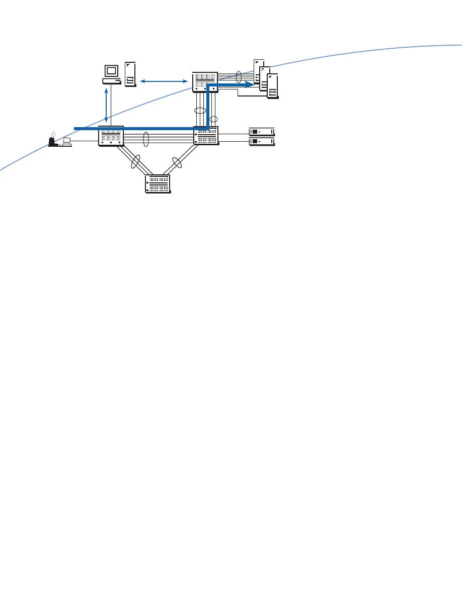
In Nortel Networks’ Passport* Campus
Solution, COPS will be used by Optivity*
Policy Services (COPS server) and the
Passport Enterprise and Routing Switches
(COPS clients) to communicate QoS
policies defined at the policy server to the
switches for enforcement (see Figure 2).
Figure 2: Passport Campus Solution and Optivity Policy Services.
Data
Passport 1000
Routing Switch
Server Farm
Passport 700
Server Switch
Passport 8000
Routing Switch
End Station can set
802.1p or DSCP field
Routing Switch validates
using policy server and sets/resets
DSCP using Express Classification
Routing Switch policies,
shapes and forwards
classified frames
Policy Server communicates
filter and queuing rules using
Common Open Policy Services
Server Switch ensures most
appropriate server used,
depending on loads and
response times
Optivity Policy Services
and Management

after. Unintended release of a required
VCC may trigger the setup process. In
certain circumstances, this can lead to
instability in the network.
The most critical components of the
LAN Emulation Service are the LES and
BUS, without which an ELAN cannot
function. Because each ELAN can only
be served by a single LES and BUS, these
components need to be backed up
by other LESs and BUSs to prevent
any single point of failure stopping
communication between the possibly
hundreds or even thousands of end stations
attached to an ELAN. In addition, the
single LES or BUS represents a potential
performance bottleneck.
Thus, it became necessary for the LAN
Emulation Service components to be
replicated for redundancy and elimination
of single points of failures, and distributed
for performance.
ATM LAN Emulation v2
To enable communication between
the redundant and distributed LAN
Emulation Service components, as well as
other functional enhancements, LANE v1
was re-specified as LANE v2; it now
comprises two separate protocols:
•
LUNI:
LAN Emulation User Network
Interface (approved July 1997)
•
LNNI:
LAN Emulation Network-Network
Interface (approved February 1999).
Gigabit Ethernet and ATM: A Technology Perspective White Paper
9
Figure 3: LAN Emulation v1 Connections and Functions.
Point-to-point or
Connection Name
Uni- or Bi-directional
Point-to-multipoint
Used for communication
Configuration Direct VCC
Bi-directional
Point-to-point
Between an LECS and an LEC
Control Direct VCC
Bi-directional
Point-to-point
Between an LES and its LECs**
Control Distribute VCC
Uni-directional
Point-to-multipoint
From an LES to its LECs
Multicast Send VCC
Bi-directional
Point-to-point
Between a BUS and an LEC
Multicast Forward VCC
Uni-directional
Point-to-multipoint
From a BUS to its LECs
Data Direct VCC
Bi-directional
Point-to-point
Between an LEC and another LEC
**Note: There is a difference between LECS with an uppercase “S” (meaning LAN Emulation Configuration Server) and LECs with a lowercase “s”
meaning LAN Emulation Clients, or more than one LEC) at the end of the acronym.
LUNI, among other enhancements,
added the Selective Multicast Server
(SMS), to provide a more efficient means
of forwarding multicast traffic, which
was previously performed by the BUS.
SMS thus offloads much of the multicast
processing from the BUS, allowing the
BUS to focus more on the forwarding
of broadcast traffic and traffic with
yet-to-be-resolved LAN destinations.
LNNI provides for the exchange of
configuration, status, control coordination,
and database synchronization between
redundant and distributed components
of the LAN Emulation Service.
However, each improvement adds new
complexity. Additional protocols are
required and additional VCCs need to be
established, maintained, and monitored
for communication between the new
LAN Emulation Service components and
LECs. For example, all LESs serving an
ELAN communicate control messages to
each other through a full mesh of Control
Coordinate VCCs. These LESs must also
synchronize their LAN-ATM address
databases, using the Server Cache
Synchronization Protocol (SCSP — RFC
2334), across the Cache Synchronization
VCC. Similarly, all BUSs serving an
ELAN must be fully connected by a
mesh of Multicast Forward VCCs used
to forward data.
• Only one Broadcast and Unknown
Server (BUS) per ELAN to forward
broadcast frames, multicast frames, and
frames for destinations whose LAN or
ATM address is as yet unknown.
• One or more LAN Emulation Clients
(LEC) to represent the end systems.
This is further complicated by whether
the end system is a LAN switch to
which other Ethernet end stations are
attached, or whether it is an ATM-
directly attached end station. A LAN
switch requires a proxy LEC, whereas
an ATM-attached end station requires
a non-proxy LEC.
Collectively, the LECS, LES, and BUS
are known as the LAN Emulation
Services. Each LEC (proxy or non-proxy)
communicates with the LAN Emulation
Services using different virtual channel
connections (VCCs) and LAN Emulation
User Network Interface (LUNI) protocols.
Figure 3 shows the VCCs used in
LANE v1.
Some VCCs are mandatory — once
established, they must be maintained if
the LEC is to participate in the ELAN.
Other VCCs are optional — they may or
may not be established and, if established,
they may or may not be released there-
Unicast traffic from a sending LEC is
initially forwarded to a receiving LEC via
the BUS. When a Data Direct VCC has
been established between the two LECs,
the unicast traffic is then forwarded via
the direct path. During the switchover
from the initial to the direct path, it is
possible for frames to be delivered out of
order. To prevent this possibility, LANE
requires an LEC to either implement the
Flush protocol, or for the sending LEC to
delay transmission at some latency cost.
The forwarding of multicast traffic
from an LEC depends on the availability
of an SMS:
• If an SMS is not available, the LEC
establishes the Default Multicast Send
VCC to the BUS that, in turn, will
add the LEC as a leaf to its Default
Multicast Forward VCC. The BUS
is then used for the forwarding of
multicast traffic.
address database with its LES using
SCSP across Cache Synchronization
VCCs.
Figure 4 shows the additional connections
required by LANE v2.
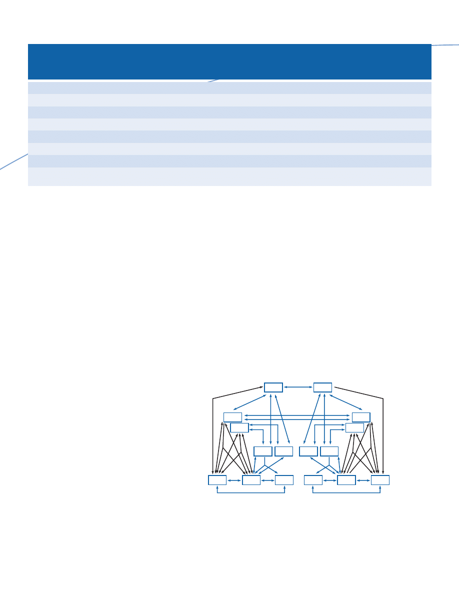
This multitude of control and coordina-
tion connections, as well as the exchange
of control frames, consumes memory,
processing power, and bandwidth, just
so that a Data Direct VCC can finally be
established for persistent communication
between two end systems. The complexity
can be seen in Figure 5.
Gigabit Ethernet and ATM: A Technology Perspective White Paper
10
• If an SMS is available, the LEC can
establish, in addition to the Default
Multicast Send VCC to the BUS, a
Selective Multicast Send VCC to the
SMS. In this case, the BUS will add the
LEC as a leaf to its Default Multicast
Forward VCC and the SMS will add
the LEC as a leaf to its Selective
Multicast Forward VCC. The BUS is
then used initially to forward multicast
traffic until the multicast destination is
resolved to an ATM address, at which
time the SMS is used. The SMS also
synchronizes its LAN-ATM multicast
Figure 4: LAN Emulation v2 Additional Connections and/or Functions.
Point-to-point or
Connection Name
Uni- or Bi-directional
Point-to-multipoint
Used for communication
LECS Synchronization VCC
Bi-directional
Point-to-point
Between LECSs
Configuration Direct VCC
Bi-directional
Point-to-point
Between an LECS and an LEC, LES or BUS
Control Coordinate VCC
Bi-directional
Point-to-point
Between LESs
Cache Synchronization VCC
Bi-directional
Point-to-point
Between an LES and its SMSs
Default Multicast Send VCC
Bi-directional
Point-to-point
Between a BUS and an LEC (as in v1)
Default Multicast Forward VCC
Uni-directional
Point-to-multipoint
From a BUS to its LECs and other BUSs
Selective Multicast Send VCC
Bi-directional
Point-to-point
Between an SMS and an LEC
Selective Multicast Forward VCC
Uni-directional
Point-to-multipoint
From an SMS to its LECs
Figure 5: Complexity of ATM LAN Emulation.
LECS
LECS
SMS
SMS
LEC
LEC
LEC
LEC
LEC
LEC
SMS
SMS
LES
LES
BUS
BUS
2
2
3
4
6
6
6
6
6
6
4
7
7
8
7
7
8
9
9
9
9**
10**
9
5
2
2
3
4
4
5
1
1
1
1
1
1
1
1
11
1 Configuration Direct VCC
2 Control Direct VCC
3 Control Distribute VCC
4 Default Multicast Send VCC
5 Default Multicast Forward VCC
6 Data Direct VCC
** may be combined into one dual function VCC between two neighbor LESs
7 Selective Multicast VCC
8 Selective Multicast Forward VCC
9 Cache Sync-only VCC
10 Control Coordinate-only VCC
11 LECS Sync VCC
Gigabit Ethernet and ATM: A Technology Perspective White Paper
11
Figure 6: AAL-5 CPCS-PDU.
AAL-5 Encapsulation
In addition to the complexity of connections
and protocols, the data carried over
LANE uses ATM Adaptation Layer-5
(AAL-5) encapsulation, which adds
overhead to the Ethernet frame. The
Ethernet frame is stripped of its Frame
Check Sequence (FCS); the remaining
fields are copied to the payload portion
of the CPCS-PDU, and a 2-byte LANE
header (LEH) is added to the front, with
an 8-byte trailer at the end. Up to 47
pad bytes may be added, to produce a
CPCS-PDU that is a multiple of 48,
the size of an ATM cell payload.
The CPCS-PDU also has to be segmented
into 53-byte ATM cells before being
transmitted onto the network. At the
receiving end, the 53-byte ATM cells have
to be decapsulated and reassembled into
the original Ethernet frame.
Figure 6 shows the CPCS-PDU that is
used to transport Ethernet frames over
LANE.
Gigabit Ethernet LAN
In contrast, a Gigabit Ethernet LAN
backbone does not have the complexity
and overhead of control functions,
data encapsulation and decapsulation,
segmentation and reassembly, and control
and data connections required by an
ATM backbone.
As originally intended, at least for initial
deployment in the LAN environment,
Gigabit Ethernet uses full-duplex
transmission between switches, or
between a switch and a server in a server
farm — in other words, in the LAN
backbone. Full-duplex Gigabit Ethernet
is much simpler, and does not suffer
from the complexities and deficiencies
of half-duplex Gigabit Ethernet, which
uses the CSMA/CD protocol, Carrier
Extension, and frame bursting.
CPCS-PDU Trailer
Bytes 1-65535 0-47
1
1 2
4
LEH CPCS-PDU Payload Pad CPCS-UU CPI Length CRC
CPCS-PDU
Bytes 8
6
6
2
46 to 1500
4
Preamble/
Destination
Source Length/
SFD
Address Address Type
64 min to 1518 bytes max
Data Pad FCS
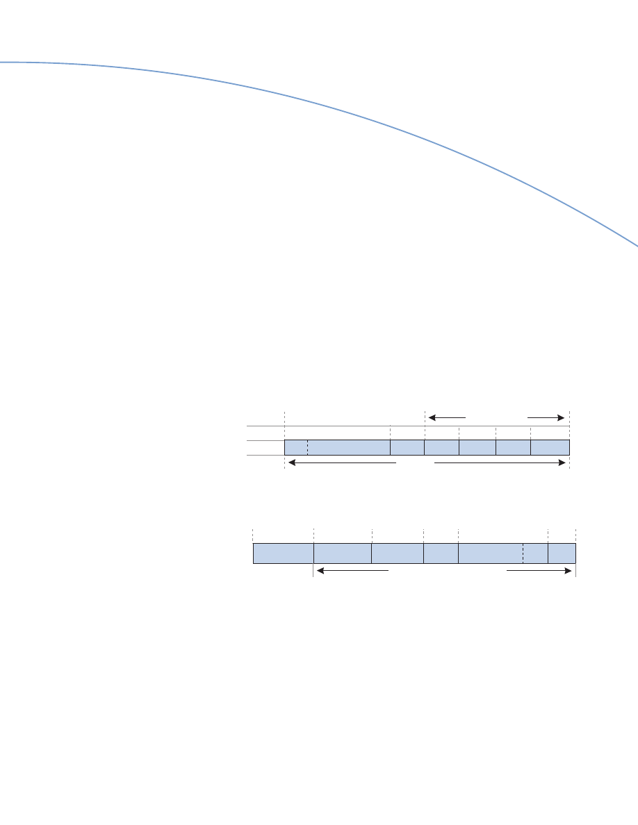
Figure 7: Full-Duplex Gigabit Ethernet Frame Format
(no Carrier Extension).
Frame Format (Full-Duplex)
Full-duplex Gigabit Ethernet uses the
same frame format as Ethernet and Fast
Ethernet, with a minimum frame length
of 64 bytes and a maximum of 1518 bytes
(including the FCS but excluding the
Preamble/SFD). If the data portion is less
than 46 bytes, pad bytes are added to
produce a minimum frame size of 64 bytes.
Figure 7 shows the same frame format for
Ethernet, Fast Ethernet and full-duplex
Gigabit Ethernet that enables the seamless
integration of Gigabit Ethernet campus
backbones with the Ethernet and
Fast Ethernet desktops and servers
they interconnect.
Frame Format (Half-Duplex)
Because of the greatly increased speed of
propagation and the need to support
practical network distances, half-duplex
Gigabit Ethernet requires the use of the
Carrier Extension. The Carrier Extension
provides a minimum transmission length
of 512 bytes. This allows collisions to be
detected without increasing the minimum
frame length of 64 bytes; thus, no changes
are required to higher layer software, such
as network interface card (NIC) drivers
and protocol stacks.
With half-duplex transmission, if the data
portion is less than 46 bytes, pad bytes
are added in the Pad field to increase
the minimum (non-extended) frame to
64 bytes. In addition, bytes are added
in the Carrier Extension field so that a
minimum of 512 bytes for transmission is
generated. For example, with 46 bytes of
data, no bytes are needed in the Pad field,
and 448 bytes are added to the Carrier
Extension field. On the other hand, with
494 or more (up to 1500) bytes of data,
no pad or Carrier Extension is needed.
“Goodput” Efficiency
With full-duplex Gigabit Ethernet,
the good throughput (“goodput”) in
a predominantly 64-byte frame size
environment, where no Carrier Extension
is needed, is calculated as follows (where
SFD=start frame delimiter, and
IFG=interframe gap):
64 bytes (frame)
[64 bytes (frame)
+
8 bytes (SFD)
+
12 bytes (IFG)]
=
76 % approx.
This goodput translates to a forwarding
rate of 1.488 million packets per second
(Mpps), known as the wirespeed rate.
With Carrier Extension, the resulting
goodput is very much reduced:
64 bytes (frame)
[512 bytes (frame with CE)
+
8 bytes (SFD)
+
12 bytes (IFG)]
=
12 % approx.
In ATM and Gigabit Ethernet comparisons,
this 12 percent figure is sometimes quoted
as evidence of Gigabit Ethernet’s inefficiency.
However, this calculation is only applicable
to half-duplex (as opposed to full-duplex)
Gigabit Ethernet. In the backbone and
server-farm connections, the vast majority
(if not all) of the Gigabit Ethernet
deployed will be full-duplex.
Mapping Ethernet Frames
into ATM LANE Cells
As mentioned previously, using ATM
LAN Emulation as the campus backbone
for Ethernet desktops require AAL-5
encapsulation and subsequent segmentation
and reassembly.
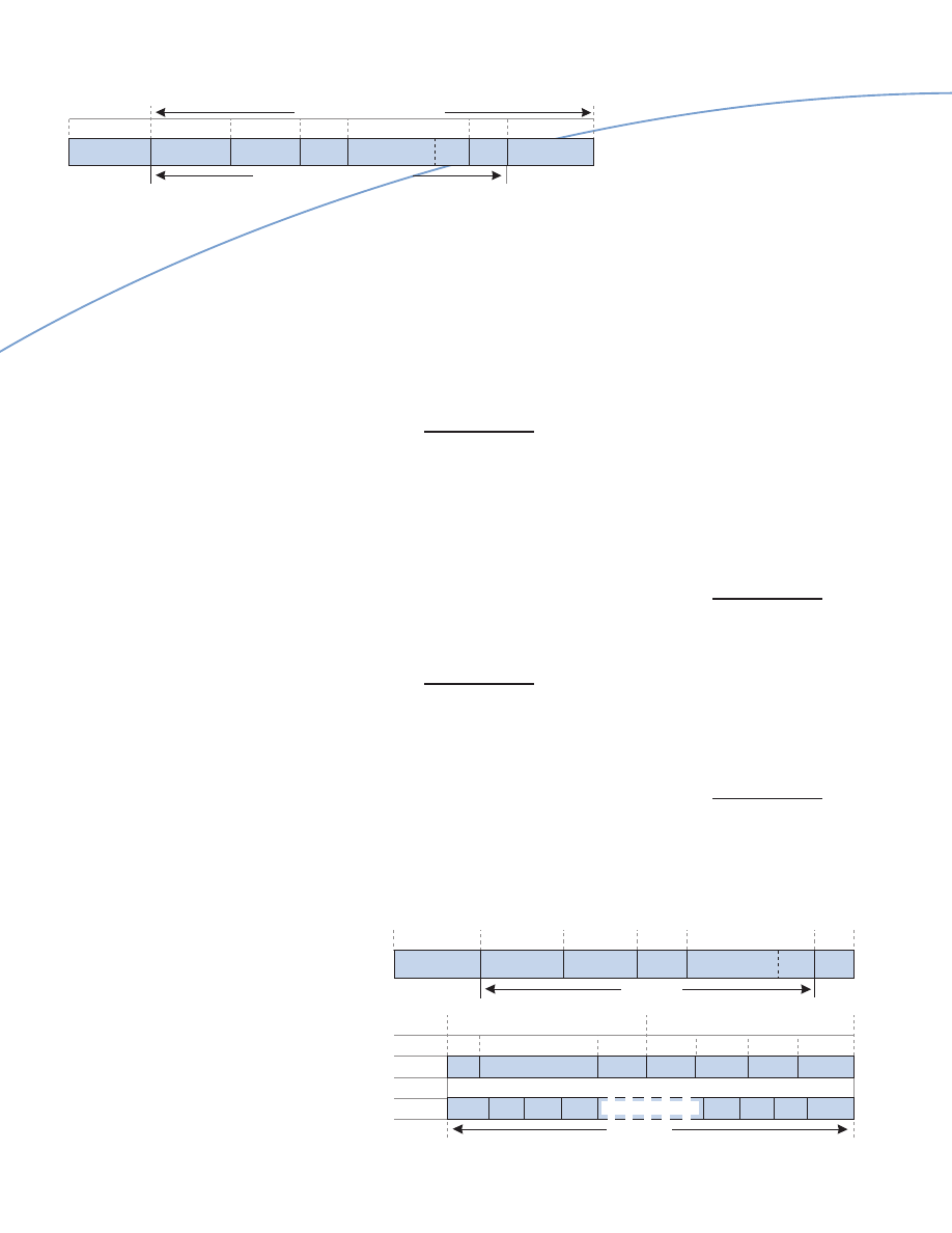
Figure 9 shows a maximum-sized
1518-byte Ethernet frame mapped into
a CPCS-PDU and segmented into 32
53-byte ATM cells, using AAL-5; this
translates into a goodput efficiency of:
1514 bytes (frame without FCS)
[32 ATM cells
x
53 bytes per ATM cell]
=
89 % approx.
For a minimum size 64-byte Ethernet
frame, two ATM cells will be required;
this translates into a goodput efficiency of:
60 bytes (frame without FCS)
[2 ATM cells
x
53 bytes per ATM cell]
=
57 % approx.
Gigabit Ethernet and ATM: A Technology Perspective White Paper
12
Figure 9: Mapping Ethernet Frame into ATM Cells.
Bytes 8
6
6
2
1500 4
1514 bytes
Preamble/
Destination
Source Length/
SFD
Address Address Type
Data Pad FCS
CPCS-PDU Payload
CPCS-PDU Trailer
Bytes 2 1514
12
1
1 2
4
LEH Ethernet Frame
Pad CPCS-UU CPI Length CRC
ATM Cells 1
2
3
4
29
30
31
32
CPCS-PDU
1696 bytes
Figure 8: Half-Duplex Gigabit Ethernet Frame Format
(with Carrier Extension).
Bytes 8
6
6
2
46 to 493
4
448 to 1
64 bytes min (non-extended)
512 bytes min transmission
Preamble/
Destination
Source Length/
SFD
Address Address Type
Carrier
Extension
Data Pad FCS
Gigabit Ethernet and ATM: A Technology Perspective White Paper
13
Frame Bursting
The Carrier Extension is an overhead,
especially if short frames are the predominant
traffic size. To enhance goodput, half-
duplex Gigabit Ethernet allows frame
bursting. Frame bursting allows an end
station to send multiple frames in one
access (that is, without contending for
channel access for each frame) up to
the burstLength parameter. If a frame is
being transmitted when the burst Length
threshold is exceeded, the sender is
allowed to complete the transmission.
Thus, the maximum duration of a frame
burst is 9710 bytes; this is the burst
Length (8192 bytes) plus the max Frame
Size (1518 bytes). Only the first frame is
extended if required. Each frame is spaced
from the previous by a 96-bit interframe
gap. Both sender and receiver must be
able to process frame bursting.
CSMA/CD Protocol
Full-duplex Gigabit Ethernet does not
use or need the CSMA/CD protocol.
Because of the dedicated, simultaneous,
and separate send and receive channels, it
is very much simplified without the need
for carrier sensing, collision detection,
backoff and retry, carrier extension, and
frame bursting.
Flow Control and
Congestion Management
In both ATM or Gigabit Ethernet, flow
control and congestion management
are necessary to ensure that the network
elements, individually and collectively,
are able to meet QoS objectives required
by applications using that network.
Sustained congestion in a switch, whether
ATM or Gigabit Ethernet, will eventually
result in frames being discarded. Various
techniques are employed to minimize
or prevent buffer overflows, especially
under transient overload conditions. The
difference between ATM and Gigabit
Ethernet is in the availability, reach, and
complexity (functionality and granularity)
of these techniques.
ATM Traffic and
Congestion Management
In an ATM network, the means employed
to manage traffic flow and congestion are
based on the traffic contract: the ATM
Service Category and the traffic descriptor
parameters agreed upon for a connection.
These means may include:
•
Connection Admission Control (CAC):
accepting or rejecting connections
being requested at the call setup stage,
depending upon availability of network
resources (this is the first point
of control and takes into account
connections already established).
•
Traffic Policing:
monitoring and
controlling the stream of cells entering
the network for connections accepted,
and marking out-of-profile traffic for
possible discard using Usage Parameter
Control (UPC) and the Generic Cell
Rate Algorithm (GCRA).
•
Backpressure
: exerting on the source
to decrease cell transmission rate when
congestion appears likely or imminent.
•
Congestion Notification:
notifying the
source and intervening nodes of current
or impending congestion by setting the
Explicit Forward Congestion
Indication (EFCI) bit in the cell header
(Payload Type Indicator) or using
Relative Rate (RR) or Explicit Rate
(ER) bits in Resource Management
(RM) cells to provide feedback both in
the forward and backward directions,
so that remedial action can be taken.
•
Cell Discard:
employing various discard
strategies to avoid or relieve congestion:
•
Selective Cell Discard:
dropping cells
that are non-compliant with traffic
contracts or have their Cell Loss
Priority (CLP) bit marked for
possible discard if necessary
Figure 10: Frame Bursting.
Bytes 8
52-1518
12
8 64-1518 12
8
64-1518
12
1 Frame Burst
Preamble/
MAC
Extension
Preamble/
MAC
Preamble/ MAC
SFD
Frame-1
(if needed)
SFD Frame-2
SFD
Frame-n
IFG
IFG
IFG

•
Early Packet Discard (EPD):
dropping
all the cells belonging to a frame that
is queued, but for which transmission
has not been started
•
Partial Packet Discard (PPD):
dropping
all the cells belonging to a frame that
is being transmitted (a more drastic
action than EPD)
•
Random Early Detection (RED):
dropping all the cells of randomly
selected frames (from different sources)
when traffic arrival algorithms indicate
impending congestion (thus avoiding
congestion), and preventing waves
of synchronized re-transmission
precipitating congestion collapse.
A further refinement is offered using
Weighted RED (WRED).
•
Traffic Shaping:
modifying the stream
of cells leaving a switch (to enter or
transit a network) so as to ensure
conformance with contracted profiles
and services. Shaping may include
reducing the Peak Cell Rate, limiting
the duration of bursting traffic, and
spacing cells more uniformly to reduce
the Cell Delay Variation.
Gigabit Ethernet Flow Control
For half-duplex operation, Gigabit
Ethernet uses the CSMA/CD protocol
to provide implicit flow control by
“backpressuring” the sender from
transmitting in two simple ways:
• Forcing collisions with the incoming
traffic, which forces the sender to back
off and retry as a result of the collision,
in conformance with the CSMA/CD
protocol.
• Asserting carrier sense to provide a
“channel busy” signal, which prevents
the sender from accessing the medium
to transmit, again in conformance with
the protocol.
With full-duplex operation, Gigabit
Ethernet uses explicit flow control to
throttle the sender. The IEEE 802.3x
Task Force defined a MAC Control
architecture, which adds an optional
MAC Control sub-layer above the MAC
sub-layer, and uses MAC Control frames
to control the flow. To date, only one
MAC Control frame has been defined;
this is for the PAUSE operation.
A switch or an end station can send
a PAUSE frame to stop a sender from
transmitting data frames for a specified
length of time. Upon expiration of the
period indicated, the sender may resume
transmission. The sender may also resume
transmission when it receives a PAUSE
frame with a zero time specified, indicating
the waiting period has been cancelled.
On the other hand, the waiting period
may be extended if the sender receives a
PAUSE frame with a longer period than
previously received.
Using this simple start-stop mechanism,
Gigabit Ethernet prevents frame discards
when input buffers are temporarily
depleted by transient overloads. It is only
effective when used on a single full-duplex
link between two switches, or between a
switch and an end station (server).
Because of its simplicity, the PAUSE
function does not provide flow control
across multiple links, or from end-to-end
across (or through) intervening switches.
It also requires both ends of a link (the
sending and receiving partners) to be
MAC Control-capable.
Bandwidth Scalability
Advances in computing technology have
fueled the explosion of visually and aural-
ly exciting applications for e-commerce,
whether Internet, intranet or extranet.
These applications require exponential
increases in bandwidth. As a business
grows, increases in bandwidth are also
required to meet the greater number of
users without degrading performance.
Therefore, bandwidth scalability in
the network infrastructure is critical to
supporting incremental or quantum
increases in bandwidth capacity, which is
frequently required by many businesses.
ATM and Gigabit Ethernet both provide
bandwidth scalability. Whereas ATM’s
bandwidth scalability is more granular
and extends from the desktop and over
the MAN/WAN, Gigabit Ethernet has
focused on scalability in campus networking
from the desktop to the MAN/WAN
edge. Therefore, Gigabit Ethernet provides
quantum leaps in bandwidth from
10 Mbps, through 100 Mbps, 1000
Mbps (1 Gbps), and even 10,000 Mbps
(10 Gbps) without a corresponding
quantum leap in costs.
Gigabit Ethernet and ATM: A Technology Perspective White Paper
14

Gigabit Ethernet and ATM: A Technology Perspective White Paper
15
ATM Bandwidth
ATM is scalable from 1.544 Mbps
through to 2.4 Gbps and even higher
speeds. Approved ATM Forum
specifications for the physical layer
include the following bandwidths:
• 1.544 Mbps DS1
• 2.048 Mbps E1
• 25.6 Mbps over shielded and unshielded
twisted pair copper cabling (the bandwidth
that was originally envisioned for ATM
to the desktop)
• 34.368 Mbps E3
• 44.736 Mbps DS3
• 100 Mbps over multimode fiber cabling
• 155.52 Mbps SONET/SDH over UTP
and single and multimode fiber cabling
• 622.08 Mbps SONET/SDH over single
and multimode fiber cabling
• 622.08 Mbps and 2.4 Gbps cell-
based physical layer (without any frame
structure).
Work is also in progress (as of October
1999) on 1 Gbps cell-based physical layer,
2.4 Gbps SONET/SDH, and 10 Gbps
SONET/SDH interfaces.
Inverse Multiplexing
over ATM
In addition, the ATM Forum’s Inverse
Multiplexing over ATM (IMA) standard
allows several lower-speed DS1/E1 physical
links to be grouped together as a single
higher speed logical link, over which cells
from an ATM cell stream are individually
multiplexed. The original cell stream is
recovered in correct sequence from the
multiple physical links at the receiving
end. Loss and recovery of individual links
in an IMA group are transparent to the
users. This capability allows users to:
• Interconnect ATM campus networks
over the WAN, where ATM WAN
facilities are not available by using
existing DS1/E1 facilities
• Incrementally subscribe to more
DS1/E1 physical links as needed
• Protect against single link failures
when interconnecting ATM campus
networks across the WAN
• Use multiple DS1/E1 links that are
typically lower cost than a single
DS3/E3 (or higher speed) ATM
WAN link for normal operation or
as backup links.
Gigabit Ethernet Bandwidth
Ethernet is scalable from the traditional
10 Mbps Ethernet, through 100 Mbps
Fast Ethernet, and 1000 Mbps Gigabit
Ethernet. Now that the Gigabit Ethernet
standards have been completed, the next
evolutionary step is 10 Gbps Ethernet.
The IEEE P802.3 Higher Speed Study
Group has been created to work on 10
Gbps Ethernet, with Project
Authorization Request and formation of
a Task Force targeted for November 1999
and a standard expected by 2002.
Bandwidth scalability is also possible
through link aggregation ( that is,
grouping multiple Gigabit Ethernet links
together to provide greater bandwidth
and resiliency. Work in this area of
standardization is proceeding through
the IEEE 802.3ad Link Aggregation Task
Force (see the Trunking and Link
Aggregation section of this paper).
Distance Scalability
Distance scalability is important because
of the need to extend the network across
widely dispersed campuses, and within
large multi-storied buildings, while making
use of existing UTP-5 copper cabling
and common single and multimode
fiber cabling, and without the need for
additional devices such as repeaters,
extenders, and amplifiers.
Both ATM and Gigabit Ethernet (IEEE
802.3ab) can operate easily within the
limit of 100 meters from a wiring closet
switch to the desktop using UTP-5
copper cabling. Longer distances are
typically achieved using multimode
(50/125 or 62.5/125 µm) or single mode
(9-10/125 µm) fiber cabling.

Gigabit Ethernet and ATM: A Technology Perspective White Paper
16
Figure 11: Ethernet and Fast Ethernet Supported Distances.
Ethernet
Ethernet
Ethernet
Ethernet
10BASE-T
10BASE-FL
100BASE-TX
100BASE-FX
IEEE Standard
802.3
802.3
802.3u
802.3u
Data Rate
10 Mbps
10 Mbps
100 Mbps
100 Mbps
Multimode Fiber distance
N/A
2 km
N/A
412 m (half duplex)
2 km (full duplex)
Singlemode Fiber distance
N/A
25 km
N/A
20 km
Cat 5 UTP distance
100 m
N/A
100 m
N/A
STP/Coax distance
500 m
N/A
100 m
N/A
Gigabit Ethernet Distances
Figure 11 shows the maximum distances
supported by Ethernet and Fast Ethernet,
using various media.
IEEE 802.3z Gigabit Ethernet
– Fiber Cabling
IEEE 802.3u-1995 (Fast Ethernet)
extended the operating speed of
CSMA/CD networks to 100 Mbps over
both UTP-5 copper and fiber cabling.
The IEEE P802.3z Gigabit Ethernet Task
Force was formed in July 1996 to develop
a Gigabit Ethernet standard. This work
was completed in July 1998 when the
IEEE Standards Board approved the
IEEE 802.3z-1998 standard.
The IEEE 802.3z standard specifies the
operation of Gigabit Ethernet over existing
single and multimode fiber cabling. It
also supports short (up to 25m) copper
jumper cables for interconnecting switches,
routers, or other devices (servers) in a
single computer room or wiring closet.
Collectively, the three designations —
1000BASE-SX, 1000BASE-LX and
1000BASE-CX — are referred to as
1000BASE-X.
Figure 12 shows the maximum distances
supported by Gigabit Ethernet, using
various media.
1000BASE-X Gigabit Ethernet is capable
of auto-negotiation for half- and full-duplex
operation. For full-duplex operation,
auto-negotiation of flow control includes
both the direction and symmetry
of operation — symmetrical and
asymmetrical.
IEEE 802.3ab Gigabit Ethernet
— Copper Cabling
For Gigabit Ethernet over copper cabling,
an IEEE Task Force started developing a
specification in 1997. A very stable draft
specification, with no significant technical
changes, had been available since July
1998. This specification, known as IEEE
802.3ab, is now approved (as of June
1999) as an IEEE standard by the IEEE
Standards Board.
The IEEE 802.3ab standard specifies the
operation of Gigabit Ethernet over distances
up to 100m using 4-pair 100 ohm
Category 5 balanced unshielded twisted
pair copper cabling. This standard is also
known as the 1000BASE-T specification;
it allows deployment of Gigabit Ethernet
in the wiring closets, and even to the
desktops if needed, without change to the
UTP-5 copper cabling that is installed in
many buildings today.
Trunking and
Link Aggregation
Trunking provides switch-to-switch
connectivity for ATM and Gigabit
Ethernet. Link Aggregation allows
multiple parallel links between switches,
or between a switch and a server, to
provide greater resiliency and bandwidth.
While switch-to-switch connectivity
for ATM is well-defined through the
NNI and PNNI specifications, several
vendor-specific

Gigabit Ethernet and ATM: A Technology Perspective White Paper
17
protocols are used for Gigabit Ethernet,
with standards-based connectivity to be
provided once the IEEE 802.3ad Link
Aggregation standard is complete.
Nortel Networks is actively involved in
this standards effort, while providing
highly resilient and higher bandwidth
Multi-Link Trunking (MLT) and Gigabit
LinkSafe technology in the interim.
ATM PNNI
ATM trunking is provided through NNI
(Network Node Interface or Network-to-
Network Interface) using the Private NNI
(PNNI) v1.0 protocols, an ATM Forum
specification approved in March 1996.
To provide resiliency, load distribution
and balancing, and scalability in
bandwidth, multiple PNNI links may be
installed between a pair of ATM switches.
Depending on the implementation,
these parallel links may be treated for
Connection Admission Control (CAC)
procedures as a single logical aggregated
link. The individual links within a set of
paralleled links may be any combination
of the supported ATM speeds. As more
bandwidth is needed, more PNNI links
may be added between switches as necessary
without concern for the possibility of
loops in the traffic path.
By using source routing to establish a path
(VCC) between any source and destination
end systems, PNNI automatically eliminates
the forming of loops. The end-to-end
path, computed at the ingress ATM
switch using Generic Connection
Admission Control (GCAC) procedures,
is specified by a list of ATM nodes known
as a Designated Transit List (DTL).
Computation based on default parameters
will result in the shortest path meeting the
requirements, although preference may be
given to certain paths by assigning lower
Administrative Weight to preferred links.
This DTL is then validated by local CAC
procedures at each ATM node in the list.
If an intervening node finds the path is
invalid, maybe as a result of topology or
link state changes in the meantime, that
node is able to automatically “crank”
the list back to the ingress switch for
recomputation of a new path. An ATM
switch may perform path computation as
a background task before calls are received
(to reduce latency during call setups),
or when a call request is received (for
real-time optimized path at the cost of
some setup delay), or both (for certain
QoS categories), depending on user
configuration.
PNNI also provides performance scalability
when routing traffic through an ATM
network, using the hierarchical structure
of ATM addresses. An individual ATM
end system in a PNNI peer group can
be reached using the summary address
for that peer group, similar to using the
network and subnet ID portions of an
IP address. A node whose address does
not match the summary address (the
non-matching address is known as a
foreign address) can be explicitly set
to be reachable and advertised.
Figure 12: Gigabit Ethernet Supported Distances.
1000BASE-SX
1000BASE-LX
1000BASE-CX
1000BASE-T
IEEE Standard
802.3z
802.3z
802.3z
802.3ab
Data Rate
1000 Mbps
1000 Mbps
1000 Mbps
1000 Mbps
Optical Wavelength (nominal)
850 nm (shortwave)
1300 nm (longwave)
N/A
N/A
Multimode Fiber (50 (m) distance
525 m
550 m
N/A
N/A
Multimode Fiber (62.5 (m) distance
260 m
550 m
N/A
N/A
Singlemode Fiber (10 (m) distance
N/A
3 km
N/A
N/A
UTP-5 100 ohm distance
N/A
N/A
N/A
100m
STP 150 ohm distance
N/A
N/A
25 m
N/A
Number of Wire Pairs/Fiber
2 fiber
2 fiber
2 pairs
4 pairs
Connector Type
Duplex SC
Duplex SC
Fibre Channel-2
RJ-45
or DB-9
Note: distances are for full duplex, the expected mode of operation in most cases.

A Peer Group Leader (PGL) may represent
the nodes in the peer group at a higher
level. These PGLs are logical group nodes
(LGNs) that form higher-level peer
groups, which allow even shorter summary
addresses. These higher-level peer groups
can be represented in even higher peer
groups, thus forming a hierarchy. By
using this multi-level hierarchical routing,
less address, topology, and link state
information needs to be advertised across
an ATM network, allowing scalability as
the number of nodes grow.
However, this rich functionality comes
with a price. PNNI requires memory,
processing power, and bandwidth from
the ATM switches for maintaining state
information, topology and link state
update exchanges, and path computation.
PNNI also results in greater complexity
in hardware design, software algorithms,
switch configuration, deployment, and
operational support, and ultimately much
higher costs.
ATM UNI Uplinks
versus NNI Risers
PNNI provides many benefits with
regard to resiliency and scalability when
connecting ATM switches in the campus
backbone. However, these advantages are
not available in most ATM installations
where the LAN switches in the wiring
closets are connected to the backbone
switches using ATM UNI uplinks. In
such connections, the end stations
attached to the LAN switch are associated,
directly or indirectly (through VLANs),
with specific proxy LECs located in the
uplinks. An end station cannot be associated
with more than one proxy LEC active in
separate uplinks at any one time. Hence,
no redundant path is available if the proxy
LEC (meaning uplink or uplink path)
representing the end stations should fail.
While it is possible to have one uplink
active and another on standby, connected
to the backbone via a different path and
ready to take over in case of failure, very
few ATM installations have implemented
this design for reasons of cost, complexity,
and lack of this capability from the
switch vendor.
One solution is provided by the Nortel
Networks Centillion* 50/100 and System
5000BH/BHC LAN-ATM Switches.
These switches provide Token-Ring and
Ethernet end station connectivity on the
one (desktop) side and “NNI riser
uplinks” to the core ATM switches on
the other (backbone) side. Because these
“NNI risers” are PNNI uplinks, the
LAN-to-ATM connectivity enjoys all
the benefits of PNNI.
Gigabit Ethernet
Link Aggregation
With Gigabit Ethernet, multiple physical
links may be installed between two
switches, or between a switch and a server,
to provide greater bandwidth and resiliency.
Typically, the IEEE 802.1d Spanning Tree
Protocol (STP) is used to prevent loops
forming between these parallel links, by
blocking certain ports and forwarding on
others so that there is only one path
between any pair of source-destination
end stations. In doing so, STP incurs
some performance penalty when
converging to a new spanning tree structure
after a network topology change.
Although most switches are plug-and-play,
with default STP parameters, erroneous
configuration of these parameters can lead
to looping, which is difficult to resolve. In
addition, by blocking certain ports, STP
will allow only one link of several parallel
links between a pair of switches to carry
traffic. Hence, scalability of bandwidth
between switches cannot be increased by
adding more parallel links as required,
although resiliency is thus improved.
To overcome the deficiencies of STP,
various vendor-specific capabilities are
offered to increase the resiliency, load
distribution and balancing, and scalability
in bandwidth, for parallel links between
Gigabit Ethernet switches.
For example, the Nortel Networks
Passport Campus Solution offers Multi-
Link Trunking and Gigabit Ethernet
LinkSafe:
Multi-Link Trunking (MLT)
that allows
up to four physical connections between
two Passport 1000 Routing Switches, or
Gigabit Ethernet and ATM: A Technology Perspective White Paper
18

Gigabit Ethernet and ATM: A Technology Perspective White Paper
19
a BayStack* 450 Ethernet Switch and
an Passport 1000 Routing Switch, to
be grouped together as a single logical
link with much greater resiliency and
bandwidth than is possible with several
individual connections.
Each MLT group may be made up
of Ethernet, Fast Ethernet or Gigabit
Ethernet physical interfaces; all links
within a group must be of the same media
type (copper or fiber), have the same
speed and half- or full-duplex settings,
and belong to the same Spanning Tree
group, although they need not be from
the same interface module within a
switch. Loads are automatically balanced
across the MLT links, based on source
and destination MAC addresses (bridged
traffic), or source and destination IP
addresses (routed traffic). Up to eight
MLT groups may be configured in an
Passport 1000 Routing Switch.
Gigabit Ethernet LinkSafe
that provides
two Gigabit Ethernet ports on an Passport
1000 Routing Switch interface module
to connect to another similar module on
another switch, with one port active and
the other on standby, ready to take over
automatically should the active port or
link fails. LinkSafe is used for riser and
backbone connections, with each link
routed through separate physical paths
to provide a high degree of resiliency
protection against a port or link failure.
An important capability is that virtual
LANs (VLANs) distributed across multiple
switches can be interconnected, with or
without IEEE 802.1Q VLAN Tagging,
using MLT and Gigabit Ethernet trunks.
With MLT and Gigabit Ethernet
LinkSafe redundant trunking and link
aggregation, the BayStack 450 Ethernet
Switch and Passport 1000 Routing Switch
provide a solution that is comparable
to ATM PNNI in its resilience and
incremental scalability, and is superior
in its simplicity.
IEEE P802.3ad
Link Aggregation
In recognition of the need for open
standards and interoperability, Nortel
Networks actively leads in the IEEE
P802.3ad Link Aggregation Task Force,
authorized by the IEEE 802.3 Trunking
Study Group in June 1998, to define
a link aggregation standard for use on
switch-to-switch and switch-to-server
parallel connections. This standard is
currently targeted for availability in
early 2000.
The IEEE P802.3ad Link Aggregation is
an important full-duplex, point-to-point
technology for the core LAN infrastructure
and provides several benefits:
• Greater bandwidth capacity, allowing
parallel links between two switches, or
a switch and a server, to be aggregated
together as a single logical pipe with
multi-Gigabit capacity (if necessary);
traffic is automatically distributed
and balanced over this pipe for high
performance.
• Incremental bandwidth scalability,
allowing more links to be added
between two switches, or a switch and
a server, only when needed for greater
performance, from a minimal initial
hardware investment, and with minimal
disruption to the network.
• Greater resiliency and fault-tolerance,
where traffic is automatically reassigned
to remaining operative links, thus
maintaining communication if individual
links between two switches, or a switch
and a server, fail.
• Flexible and simple migration vehicle,
where Ethernet and Fast Ethernet
switches at the LAN edges can have
multiple lower-speed links aggregated
to provide higher-bandwidth transport
into the Gigabit Ethernet core.
A brief description of the IEEE P802.3ad
Link Aggregation standard (which may
change as it is still fairly early in the
standards process) follows.
A physical connection between two
switches, or a switch and a server, is
known as a link segment. Individual link
segments of the same medium type and
speed may make up a Link Aggregation
Group (LAG), with a link segment
belonging to only one LAG at any one
time. Each LAG is associated with a single
MAC address.

Frames that belong logically together
(for example, to an application being used
at a given instance, flowing in sequence
between a pair of end stations) are treated
as a conversation (similar to the concept
of a “flow”). Individual conversations are
aggregated together to form an
Aggregated Conversation, according to
user-specified Conversation Aggregation
Rules, which may specify aggregation, for
example, on the basis of source/destination
address pairs, VLAN ID, IP subnet, or
protocol type. Frames that are part of a
given conversation are transmitted on
a single link segment within a LAG to
ensure in-sequence delivery.
A Link Aggregation Control Protocol
is used to exchange link configuration,
capability, and state information between
adjacent switches, with the objective
of forming LAGs dynamically. A Flush
protocol, similar to that in ATM LAN
Emulation, is used to flush frames in
transit when links are added or removed
from a LAG.
Among the objectives of the IEEE
P802.3ad standard are automatic
configuration, low protocol overheads,
rapid and deterministic convergence when
link states change, and accommodation of
aggregation-unaware links.
Technology
Complexity and Cost
Two of the most critical criteria in the
technology decision are the complexity
and cost of that technology. In both
aspects, simple and inexpensive Gigabit
Ethernet wins hands down over complex
and expensive ATM — at least in
enterprise networks.
ATM is fairly complex because it is a
connection-oriented technology that has
to emulate the operation of connection-
less LANs. As a result, additional physical
and logical components, connections,
and protocols have to be added, with
the attendant need for understanding,
configuration, and operational support.
Unlike Gigabit Ethernet (which is largely
plug-and-play), there is a steep learning
curve associated with ATM, in product
development as well as product usage.
ATM also suffers from a greater number
of interoperability and compatibility
issues than does Gigabit Ethernet, because
of the different options vendors implement
in their ATM products. Although
interoperability testing does improve the
situation, it also adds time and cost to
ATM product development.
Because of the greater complexity,
the result is also greater costs in:
• Education and training
• Implementation and deployment
• Problem determination and resolution
• Ongoing operational support
• Test and analysis equipment, and other
management tools.
Integration of Layer 3
and Above Functions
Both ATM and Gigabit Ethernet provide
the underlying internetwork over which
IP packets are transported. Although
initially a Layer 2 technology, ATM
functionality is creeping upwards in the
OSI Reference Model. ATM Private
Network Node Interface (PNNI) provides
signaling and OSPF-like best route
determination when setting up the path
from a source to a destination end system.
Multiprotocol Over ATM (MPOA)
allows short-cut routes to be established
between two communicating ATM end
systems located in different IP subnets,
completely bypassing intervening routers
along the path.
In contrast, Gigabit Ethernet is strictly
a Layer 2 technology, with much of the
other needed functionality added above
it. To a large extent, this separation of
functions is an advantage because changes
to one function do not disrupt another
if there is clear modularity of functions.
This decoupling was a key motivation in
the original development of the 7-layer
OSI Reference Model. In fact, the
complexity of ATM may be due to the
rich functionality all provided “in one
hit,” unlike the relative simplicity of
Gigabit Ethernet, where higher layer
functionality is kept separate from,
and added “one at a time” to, the basic
Physical and Data Link functions.
Gigabit Ethernet and ATM: A Technology Perspective White Paper
20

Gigabit Ethernet and ATM: A Technology Perspective White Paper
21
MPOA and NHRP
A traditional router provides two basic
Layer 3 functions: determining the best
possible path to a destination using
routing control protocols such as RIP
and OSPF (this is known as the routing
function), and then forwarding the frames
over that path (this is known as the
forwarding function).
Multi-Protocol Over ATM (MPOA)
enhances Layer 3 functionality over ATM
in three ways:
• MPOA uses a Virtual Router model to
provide greater performance scalability
by allowing the typically centralized
routing control function to be divorced
from the data frame forwarding function,
and distributing the data forwarding
function to access switches on the
periphery of the network. This
“separation of powers” allows routing
capability and forwarding capability to
be distributed to where each is most
effective, and allows each to be scaled
when needed without interference
from the other.
• MPOA enables paths (known as short-
cut VCCs) to be directly established
between a source and its destination,
without the hop-by-hop, frame-by-
frame processing and forwarding that is
necessary in traditional router networks.
Intervening routers, which are potentially
performance bottlenecks, are completely
bypassed, thereby enhancing forwarding
performance.
• MPOA uses fewer resources in the form
of VCCs. When traditional routers are
used in an ATM network, one Data
Direct VCC (DDVCC) must be
established between a source end
station and its gateway router, one
DDVCC between a destination end
station and its gateways router, and
several DDVCCs between intervening
routers along the path. With MPOA,
only one DDVCC is needed between
the source and destination end stations.
Gigabit Ethernet can also leverage a
similar capability for IP traffic using the
Next Hop Resolution Protocol (NHRP).
In fact, MPOA uses NHRP as part of the
process to resolve MPOA destination
addresses. MPOA Resolution Requests
are converted to NHRP Resolution
Requests by the ingress MPOA server
before forwarding the requests towards
the intended destination. NHRP
Resolution Responses received by the
ingress MPOA server are converted to
MPOA Resolution Responses before
being forwarded to the requesting source.
Just as MPOA shortcuts can be established
for ATM networks, NHRP shortcuts
can also be established to provide the
performance enhancement in a frame
switched network.
Gateway Redundancy
For routing between subnets in an ATM
or Gigabit Ethernet network, end stations
typically are configured with the static IP
address of a Layer 3 default gateway
router. Being a single point of failure,
sometimes with catastrophic consequences,
various techniques have been deployed to
ensure that an alternate backs this default
gateway when it fails.
With ATM, redundant and distributed
Layer 3 gateways are currently vendor-
specific. Even if a standard should emerge,
it is likely that more logical components,
protocols, and connections will need to
be implemented to provide redundant
and/or distributed gateway functionality.
Virtual Router
Redundancy Protocol
For Gigabit Ethernet, an IETF RFC 2338
Virtual Router Redundancy Protocol
(VRRP) is available for deploying
interoperable and highly resilient default
gateway routers. VRRP allows a group of
routers to provide redundant and distributed
gateway functions to end stations through
the mechanism of a virtual IP address —
the address that is configured in end
stations as the default gateway router.
At any one time, the virtual IP address
is mapped to a physical router, known
as the Master. Should the Master fail,
another router within the group is elected
as the new Master with the same virtual
IP address. The new Master automatically
takes over as the new default gateway,
without requiring configuration
changes in the end stations. In addition,
each router may be Master for a set
of end stations in one subnet while
providing backup functions for another,
thus distributing the load across
multiple routers.

Gigabit Ethernet and ATM: A Technology Perspective White Paper
22
LAN Integration
The requirements of the LAN are very
different from those of the WAN. In the
LAN, bandwidth is practically “free” once
installed, as there are no ongoing usage
costs. As long as sufficient bandwidth
capacity is provisioned (or even over-
provisioned) to meet the demand, there
may not be a need for complex techniques
to control bandwidth usage. If sufficient
bandwidth exists to meet all demand,
then complex traffic management and
congestion control schemes may not be
needed at all. For the user, other issues
assume greater importance; these include
ease of integration, manageability, flexibility
(moves, adds and changes), simplicity,
scalability, and performance.
Seamless Integration
ATM has often been touted as the
technology that provides seamless
integration from the desktop, over the
campus and enterprise, right through
to the WAN and across the world. The
same technology and protocols are used
Broadcast and Multicast
Broadcasts and multicasts are very natural
means to send traffic from one source to
multiple recipients in a connectionless
LAN. Gigabit Ethernet is designed for
just such an environment. The higher-
layer IP multicast address is easily mapped
to a hardware MAC address. Using
Internet Group Management Protocol
(IGMP), receiving end stations report
group membership to (and respond to
queries from) a multicast router, so as to
receive multicast traffic from networks
beyond the local attachment. Source end
stations need not belong to a multicast
group in order to send to members of
that group.
By contrast, broadcasts and multicasts in
an ATM LAN present a few challenges
because of the connection-oriented nature
of ATM.
In each emulated LAN (ELAN), ATM
needs the services of a LAN Emulation
Server (LES) and a Broadcast and
Unknown Server (BUS) to translate from
MAC addresses to ATM addresses. These
additional components require additional
resources and complexity needed to signal,
set up, maintain, and tear down Control
Direct, Control Distribute, Multicast
Send, and Multicast Forward VCCs.
Complexity is further increased because
an ELAN can only have a single
LES/BUS, which must be backed up by
another LES/BUS to eliminate any single
points of failure. Communication
throughout. Deployment and on-going
operational support are much easier
because of the opportunity to “learn once,
do many.” One important assumption in
this scenario is that ATM would be widely
deployed at the desktops. This assumption
does not meet with reality.
ATM deployment at the desktop is
almost negligible, while Ethernet and
Fast Ethernet are very widely installed
in millions of desktop workstations and
servers. In fact, many PC vendors include
Ethernet, Fast Ethernet, and (increasingly)
Gigabit Ethernet NIC cards on the
motherboards of their workstation or
server offerings. Given this huge installed
base and the common technology that it
evolved from, Gigabit Ethernet provides
seamless integration from the desktops
to the campus and enterprise backbone
networks.
If ATM were to be deployed as the
campus backbone for all the Ethernet
desktops, then there would be a need for
frame-to-cell and cell-to-frame conversion
— the Segmentation and Reassembly
(SAR) overhead.
With Gigabit Ethernet in the campus
backbone and Ethernet to the desktops,
no cell-to-frame or frame-to-cell conversion
is needed. Not even frame-to-frame
conversion is required from one form
of Ethernet to another! Hence, Gigabit
Ethernet provides a more seamless
integration in the LAN environment.

between active and backup LES/BUS
nodes requires more virtual connections
and protocols for synchronization, failure
detection, and takeover (SCSP and LNNI).
With all broadcast traffic going through
the BUS, the BUS poses a potential
bottleneck.
For IP multicasting in a LANE network,
ATM needs the services of the BUS and,
if available (with LUNI v2), an SMS.
For IP multicasting in a Classical IP ATM
network, ATM needs the services of a
Multicast Address Resolution Server
(MARS), a Multicast Connection Server
(MCS), and the Cluster Control VCCs.
These components require additional
resources and complexity for connection
signaling, setting up, maintenance and
tearing down.
With UNI 3.0/3.1, the source must first
resolve the target multicast address to the
ATM addresses of the group members,
and then construct a point-to-multipoint
tree, with the source itself as the root to
the multiple destinations before multicast
traffic may be distributed. With UNI 4.0,
end stations may join as leaves to a point-
to-multipoint distribution tree, with or
without intervention from the root. Issues
of interoperability between the different
UNI versions are raised in either case.
Multi-LAN Integration
As a backbone technology, ATM can
interconnect physical LAN segments
using Ethernet, Fast Ethernet, Gigabit
Ethernet, and Token Ring. These are
the main MAC layer protocols in use on
campus networks today. Using ATM as
the common uplink technology and
with translational bridging functionality,
the Ethernet and Token-Ring LANs can
interoperate relatively easily.
With Gigabit Ethernet, interoperation
between Ethernet and Token-Ring LANs
requires translational bridges that transform
the frame format of one type to the other.
MAN/WAN Integration
It is relatively easy to interconnect ATM
campus backbones across the MAN or
WAN. Most ATM switches are offered
with DS1/E1, DS3/E3, SONET OC-3c/
SDH STM-1 and SONET OC-12c/
SDH STM-4 ATM interfaces that
connect directly to the ATM MAN or
WAN facilities. Some switches are offered
with DS1/E1 Circuit Emulation, DS1/E1
Inverse Multiplexing over ATM, and
Frame Relay Network and Service
Interworking capabilities that connect
to the existing non-ATM MAN or WAN
facilities. All these interfaces allow ATM
campus switches direct connections to
the MAN or WAN, without the need for
additional devices at the LAN-WAN edge.
At this time, many Gigabit Ethernet
switches do not offer MAN/WAN
interfaces. Connecting Gigabit Ethernet
campus networks across the MAN
or WAN typically requires the use of
additional devices to access MAN/WAN
facilities, such as Frame Relay, leased
lines, and even ATM networks. These
interconnect devices are typically routers
or other multiservice switches that add to
the total complexity and cost. With the
rapid acceptance of Gigabit Ethernet as
the campus backbone of choice, however,
many vendors are now offering
MAN/WAN interfaces such as ATM
Gigabit Ethernet and ATM: A Technology Perspective White Paper
23
SONET OC-3c/SDH STM-1, SONET
OC-12c/SDH STM-4, and Packet-
over-SONET/SDH in their Gigabit
Ethernet switches.
While an ATM LAN does offer seamless
integration with the ATM MAN or
WAN through direct connectivity,
the MAN/WAN for the most part will
continue to be heterogeneous, and not
homogeneous ATM. This is due to the
installed non-ATM equipment, geographical
coverage, and time needed to change.
This situation will persist more so than in
the LAN where there is a greater control
by the enterprise and, therefore, greater
ease of convergence. Even in the LAN,
the convergence is towards Ethernet and
not ATM as the underlying technology.
Technologies other than ATM will be
needed for interconnecting between
locations, and even over entire regions,
because of difficult geographical terrain
or uneconomic reach. Thus, there will
continue to be a need for technology
conversion from the LAN to the
WAN, except where ATM has been
implemented.

Another development — the widespread
deployment of fiber optic technology —
may enable the LAN to be extended over
the WAN using the seemingly boundless
optical bandwidth for LAN traffic. This
means that Gigabit Ethernet campuses
can be extended across the WAN just as
easily, perhaps even more easily and with
less cost, than ATM over the WAN.
Among the possibilities are access to Dark
Fiber with long-haul extended distance
Gigabit Ethernet (50 km or more),
Packet-over-SONET/SDH and IP
over Optical Dense Wave Division
Multiplexing.
One simple yet powerful way for extending
high performance Gigabit Ethernet
campus networks across the WAN,
especially in the metropolitan area, is the
use of Packet-over-SONET/SDH (POS,
While all these technologies are evolving,
businesses seek to minimize risks by
investing in the lower-cost Gigabit
Ethernet, rather than the higher-cost ATM.
Management Aspects
Because businesses need to be increasingly
dynamic to respond to opportunities
and challenges, the campus networking
environment is constantly in a state of
flux. There are continual moves, adds,
and changes; users and workstations form
and re-form workgroups; road warriors
take the battle to the streets, and highly
mobile users work from homes and hotels
to increase productivity.
With all these constant changes,
manageability of the campus network
is a very important selection criterion.
The more homogeneous and simpler
the network elements are, the easier they
are to manage. Given the ubiquity of
Ethernet and Fast Ethernet, Gigabit
Ethernet presents a more seamless
integration with existing network
elements than ATM. Therefore, Gigabit
Ethernet is easier to manage. Gigabit
Ethernet is also easier to manage because
of its innate simplicity and the wealth of
experience and tools available with its
predecessor technologies.
Gigabit Ethernet and ATM: A Technology Perspective White Paper
24
Figure 13: Interconnection Technologies over the MAN/WAN.
IP over ATM
IP over SONET/SDH
IP over Optical
B-ISDN
IP
ATM
IP
IP
SONET/SDH
ATM
SONET/SDH
IP
Optical
Optical
Optical
Optical
(A)
(B)
(C)
(D)
also known as IP over SONET/SDH).
SONET is emerging as a competitive
service to ATM over the MAN/WAN.
With POS, IP packets are directly
encapsulated into SONET frames,
thereby eliminating the additional
overhead of the ATM layer (see column
“C” in Figure 13).
To extend this a step further, IP packets
can be transported over raw fiber without
the overhead of SONET/SDH framing;
this is called IP over Optical (see column
“D” in Figure 13). Optical Networking
can transport very high volumes of data,
voice and video traffic over different light
wavelengths.
The pattern of traffic has also been rapidly
changing, with more than 80 percent of
the network traffic expected to traverse
the MAN/WAN, versus only 20 percent
remaining on the local campus. Given
the changing pattern of traffic, and the
emergence of IP as the dominant network
protocol, the total elimination of layers
of communication for IP over the
MAN/WAN means reduced bandwidth
usage costs and greater application
performance for the users.

Gigabit Ethernet and ATM: A Technology Perspective White Paper
25
By contrast, ATM is significantly different
from the predominant Ethernet desktops
it interconnects. Because of this difference
and its relative newness, there are few
tools and skills available to manage ATM
network elements. ATM is also more
difficult to manage because of the
complexity of logical components and
connections, and the multitude of protocols
needed to make ATM workable. On top
of the physical network topology lie a
number of logical layers, such as PNNI,
LUNI, LNNI, MPOA, QoS, signaling,
SVCs, PVCs, and soft PVCs. Logical
components are more difficult to
troubleshoot than physical elements
when problems do occur.
Standards and
Interoperability
Like all technologies, ATM and Gigabit
Ethernet standards and functions mature
and stabilize over time. Evolved from a
common technology, frame-based Gigabit
Ethernet backbones interoperate seamlessly
with the millions of connectionless,
frame-based Ethernet and Fast Ethernet
desktops and servers in today’s enterprise
campus networks. By contrast, connection-
oriented, cell-based ATM backbones need
additional functions and capabilities that
require standardization, and can easily
lead to interoperability issues.
ATM Standards
Although relatively new, ATM standards
have been in development since 1984 as
part of B-ISDN, designed to support
private and public networks. Since the
formation of the ATM Forum in 1991,
many ATM specifications were completed,
especially between 1993 and 1996.
Because of the fast pace of development
efforts during this period, a stable
environment was felt to be needed for
consolidation, implementation and inter-
operability. In April 1996, the Anchorage
Accord agreed on a collection of some 60
ATM Forum specifications that provided
a basis for stable implementation. Besides
designating a set of foundational and
expanded feature specifications, the
Accord also established criteria to ensure
interoperability of ATM products and
services between current and future
specifications. This Accord provided the
assurance needed for the adoption of
ATM and a checkpoint for further standards
development. As of July 1999, there are
more than 40 ATM Forum specifications
in various stages of development.
To promote interoperability, the ATM
Consortium was formed in October
1993, one of several consortiums at the
University of New Hampshire
InterOperability Lab (IOL). The ATM
Consortium is a grouping of ATM product
vendors interested in testing interoperability
and conformance of their ATM products
in a cooperative atmosphere, without
adverse competitive publicity.
Gigabit Ethernet Standards
By contrast, Gigabit Ethernet has evolved
from the tried and trusted Ethernet and
Fast Ethernet technologies, which have
been in use for more than 20 years. Being
relatively simple compared to ATM,
much of the development was completed
within a relatively short time. The Gigabit
Ethernet Alliance, a group of networking
vendors including Nortel Networks,
promotes the development, demonstration,
and interoperability of Gigabit Ethernet
standards. Since its formation in 1996,
the Alliance has been very successful in
helping to introduce the IEEE 802.3z
1000BASE-X, and the IEEE 802.3ab
1000BASE-T Gigabit Ethernet standards.
Similar to the ATM Consortium, the
Gigabit Ethernet Consortium was formed
in April 1997 at the University of New
Hampshire InterOperability Lab as a
cooperative effort among Gigabit
Ethernet product vendors. The objective
of the Gigabit Ethernet Consortium
is the ongoing testing of Gigabit Ethernet
products and software from both an inter-
operability and conformance perspective.
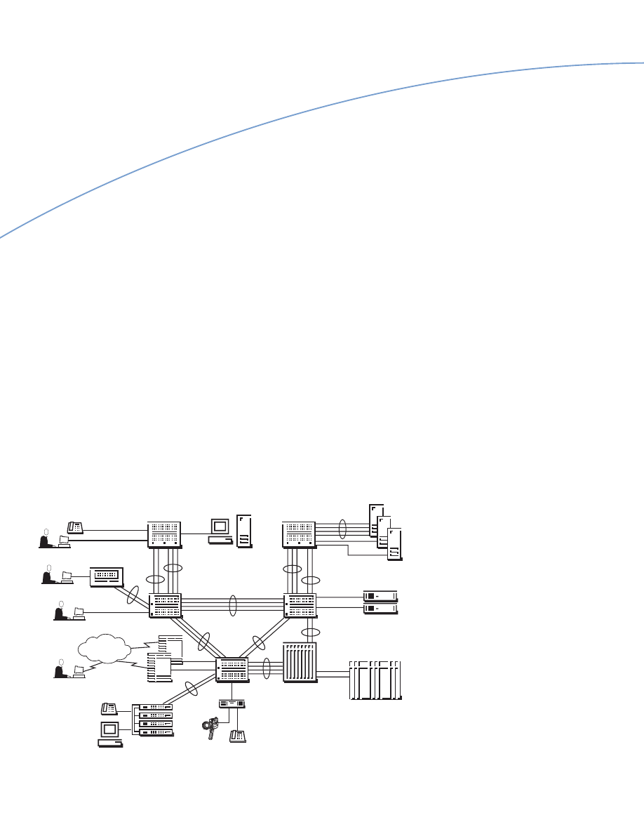
Passport
Campus Solution
In response to the market requirements
and demand for Ethernet, Fast Ethernet,
and Gigabit Ethernet, Nortel Networks
offers the Passport Campus Solution as
the best-of-breed technology for campus
access and backbone LANs. The Passport
Campus Solution (see Figure 14)
comprises the Passport 8000 Enterprise
Switch, with its edge switching and routing
capabilities, the Passport 1000 Routing
Switch family, Passport 700 Server Switch
• Up to 160 Fast Ethernet
100BASE-FX ports
• Up to 64 Gigabit Ethernet
1000BASE-SX or -LX ports
• Wirespeed switching for Ethernet,
Fast Ethernet and Gigabit Ethernet
• High resiliency through Gigabit
LinkSafe and Multi-Link Trunking
• High availability through fully
distributed switching and management
architectures, redundant and load-sharing
power supplies and cooling fans, and
ability to hot-swap all modules
• Rich functionality through support of:
• Port- and protocol-based VLANs
for broadcast containment, logical
workgroups, and easy moves, adds
and changes
• IEEE 802.1Q VLAN Tagging for
carrying traffic from multiple VLANs
over a single trunk
• IEEE 802.1p traffic prioritization
for key business applications
• IGMP, broadcast and multicast
rate limiting for efficient broadcast
containment
• Spanning Tree Protocol FastStart for
faster network convergence and recovery
• Remote Network Monitoring
(RMON), port mirroring, and Remote
Traffic Monitoring (RTM) for network
management and problem determination.
Gigabit Ethernet and ATM: A Technology Perspective White Paper
26
Figure 14: Passport Campus Solution and Optivity Policy Services.
Data
Data
Voice
Video
Data
Data
WAN
Passport 8000
Enterprise Switch
Centillion 100
Multi-LAN Switch
Passport 1000
Routing Switch
BN Router
redundant gateways
BayStack 450
Ethernet Switch
10/100/Gigabit Ethernet
MLT resiliency
OSPF
EMP
Common Open Policy Services
Differentiated Services
IP Precedence/Type of Service
IEEE 802.1Q VLAN Tag
IEEE 802.1p User Priority
Express Classification
Optivity Policy Services
& Management
Server Farm
10/100 Ethernet
MLT resiliency
Gigabit Ethernet
LinkSafe resiliency
Passport 700 Server Switch
server redundancy
& load balancing
System 390
Mainframe Server
System 5000BH
Multi-LAN Switch
Data
Voice
Voice
family, and BayStack 450 Stackable
Switch, complemented by Optivity Policy
Services for policy-enabled networking.
The following highlights key features of
the Passport 8000 Enterprise Switch, the
winner of the Best Network Hardware
award from the 1999 Annual SI Impact
Awards, sponsored by IDG’s Solutions
Integrator magazine:
• High port density, scalability
and performance
• Switch capacity of 50 Gbps,
scalable to 256 Gbps
• Aggregate throughput of 3 million
packets per second
• Less than 9 microseconds of latency
• Up to 372 Ethernet 10/100BASE-T
auto-sensing, auto-negotiating ports

Gigabit Ethernet and ATM: A Technology Perspective White Paper
27
For these reasons, Nortel Networks
recommends Gigabit Ethernet as the
technology of choice for most campus
backbone LANs. ATM was, and continues
to be, a good option where its unique and
complex functionality can be exploited,
in deployment, for example, in the
metropolitan and wide area network.
This recommendation is supported by
many market research surveys that show
users overwhelmingly favor Gigabit
Ethernet over ATM, including surveys
such as User Plans for High Performance
LANs by Infonetics Research Inc.
(March 1999), and Hub and Switch
5-Year Forecast by the Dell’Oro Group
(July 1999).
For users with investments in Centillion
50/100 and System 5000BH LAN-ATM
Switches, evolution to a Gigabit Ethernet
environment will be possible once Gigabit
Ethernet switch modules are offered in
the future.
Information on the other award-winning
members of the Passport Campus
Solution is available on Nortel Networks
website: http://www.nortelnetworks.com
Conclusion and
Recommendation
In enterprise networks, either ATM or
Gigabit Ethernet may be deployed in the
campus backbone. The key difference is
in the complexity and much higher cost
of ATM, versus the simplicity and much
lower cost of Gigabit Ethernet. While it
may be argued that ATM is richer in
functionality, pure technical consideration
is only one of the decision criteria, albeit
a very important one.
Of utmost importance is functionality
that meets today’s immediate needs at
a price that is realistic. There is no point
in paying for more functionality and
complexity than is necessary, that may
or may not be needed, and may even
be obsolete in the future. The rate of
technology change and competitive
pressures demand that the solution be
available today, before the next paradigm
shift, and before new solutions introduce
another set of completely new challenges.
Gigabit Ethernet provides a pragmatic,
viable, and relatively inexpensive (and
therefore, lower risk) campus backbone
solution that meets today’s needs and
integrates seamlessly with the omnipresence
of connectionless, frame-based Ethernet
and Fast Ethernet LANs. Enhanced by
routing switch technology such as the
Nortel Networks Passport 8000
Enterprise Switches, and policy-enabled
networking capabilities in the Nortel
Networks Optivity Policy Services,
Gigabit Ethernet provides enterprise busi-
nesses with the bandwidth, functionality,
scalability, and performance they need, at
a much lower cost than ATM.
By contrast, ATM provides a campus
backbone solution that has the disadvantages
of undue complexity, unused functionality,
and much higher cost of ownership in the
enterprise LAN. Much of the complexity
results from the multitude of additional
components, protocols, control, and
data connections required by connection-
oriented, cell-based ATM to emulate
broadcast-centric, connectionless, frame-
based LANs. While Quality of Service
(QoS) is an increasingly important
requirement in enterprise networks, there
are other solutions to the problem that are
simpler, incremental, and less expensive.
http://
www.nortelnetworks.com
*Nortel Networks, the Nortel Networks logo, the Globemark, How the World Shares Ideas, Unified Networks, BayStack, Centillion, Optivity,
and Passport are trademarks of Nortel Networks. All other trademarks are the property of their owners.
© 2000 Nortel Networks. All rights reserved. Information in this document is subject to change without notice.
Nortel Networks assumes no responsibility for any errors that may appear in this document. Printed in USA.
W P 3 7 4 0 - B / 0 4 - 0 0
United States
Nortel Networks
4401 Great America Parkway
Santa Clara, CA 95054
1-800-822-9638
Canada
Nortel Networks
8200 Dixie Road
Brampton, Ontario
L6T 5P6, Canada
1-800-466-7835
Europe, Middle East, and Africa
Nortel Networks
Les Cyclades - Immeuble Naxos
25 Allée Pierre Ziller
06560 Valbonne France
33-4-92-96-69-66
Asia Pacific
Nortel Networks
151 Lorong Chuan
#02-01 New Tech Park
Singapore 556741
65-287-2877
Caribbean and Latin America
Nortel Networks
1500 Concord Terrace
Sunrise, Florida
33323-2815 U.S.A.
954-851-8000
For more sales and product information, please call 1-800-822-9638.
Author: Tony Tan, Portfolio Marketing, Commercial Marketing
Wyszukiwarka
Podobne podstrony:
JAIN SLEE and J2EE Technologies Exposing Core Network Capabilities (2004 JavaOneSM Conference, Sess
31 411 423 Effect of EAF and ESR Technologies on the Yield of Alloying Elements
cloud computing historia, technologia, perspektywy
MICROACTUATORS AND THEIR TECHNOLOGIES
Technologia ATM, Technologia ATM
Reverse Speech and NLP Technologies changeing our world
Castells M Globalisation and identity a comparative perspective B93F1157d01
(ebook NLP) Reverse Speech and NLP Technologies changeing our world
Gigabitowy Ethernet a okablowanie strukturalne
The Third Reich Between Vision and Reality, New Perspectives on German History 1918 1945
CHECK YOUR ENGLISH VOCABULARY FOR COMPUTERS AND INFORMATION TECHNOLOGY
part2 14 Empathy and Direct Discourse Perspectives
Social networks personal values and creativity
Coopetition in Business Networks to Cooperate and Compete Simultaneously
Mobile Multimedia In Context To Atm Transport And Gsm Gprs Mobile Access Networks
więcej podobnych podstron