
EMC Proven Professional
. Copyright © 2012 EMC Corporation. All Rights Reserved
.
MODULE – 2
DATA CENTER
ENVIRONMENT
Module 2: Data Center Environment
1

EMC Proven Professional
. Copyright © 2012 EMC Corporation. All Rights Reserved
.
Upon completion of this module, you should be able to:
•
Describe the core elements of a data center
•
Describe virtualization at application and host layer
•
Describe disk drive components and performance
•
Describe host access to storage through DAS
•
Describe working and benefits of flash drives
Module 2: Data Center Environment
2
Module 2: Data Center Environment

EMC Proven Professional
. Copyright © 2012 EMC Corporation. All Rights Reserved
.
Module 2: Data Center Environment
During this lesson the following topics are covered:
•
Application and application virtualization
•
DBMS
•
Components of host system
•
Compute and memory virtualization
Lesson 1: Application, DBMS, and Host (Compute)
Module 2: Data Center Environment
3

EMC Proven Professional
. Copyright © 2012 EMC Corporation. All Rights Reserved
.
Application
•
A software program that provides logic for computing operations
•
Commonly deployed applications in a data center
Business applications – email, enterprise resource planning (ERP),
decision support system (DSS)
Management applications – resource management, performance
tuning, virtualization
Data protection applications – backup, replication
Security applications – authentication, antivirus
•
Key I/O characteristics of an application
Read intensive vs. write intensive
Sequential vs. random
I/O size
Module 2: Data Center Environment
4

EMC Proven Professional
. Copyright © 2012 EMC Corporation. All Rights Reserved
.
Application Virtualization
•
Allows application to be delivered in an isolated environment
Aggregates Operating System (OS) resources and the application
into a virtualized container
Ensures integrity of Operating System (OS) and applications
Avoids conflicts between different applications or different
versions of the same application
Module 2: Data Center Environment
5
It is the technique of presenting an application to an end user without
any installation, integration, or dependencies on the underlying
computing platform.
Application Virtualization

EMC Proven Professional
. Copyright © 2012 EMC Corporation. All Rights Reserved
.
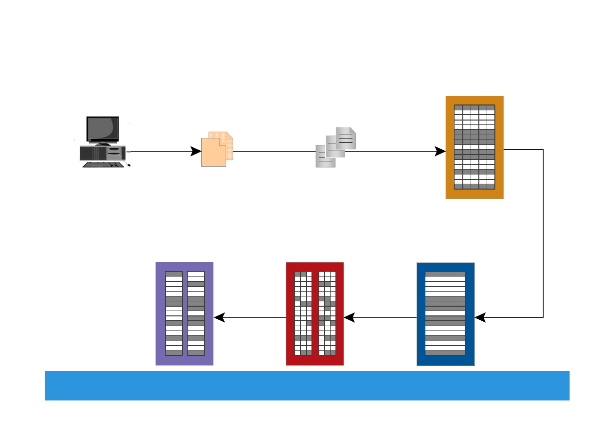
Database Management System (DBMS)
•
Database is a structured way to store data in logically organized
tables that are interrelated
Helps to optimize the storage and retrieval of data
•
DBMS controls the creation, maintenance, and use of databases
Processes an application’s request for data
Instructs the OS to retrieve the appropriate data from storage
•
Popular DBMS examples are MySQL, Oracle RDBMS, SQL Server,
etc.
Module 2: Data Center Environment
6
EMC Proven Professional
. Copyright © 2012 EMC Corporation. All Rights Reserved
.
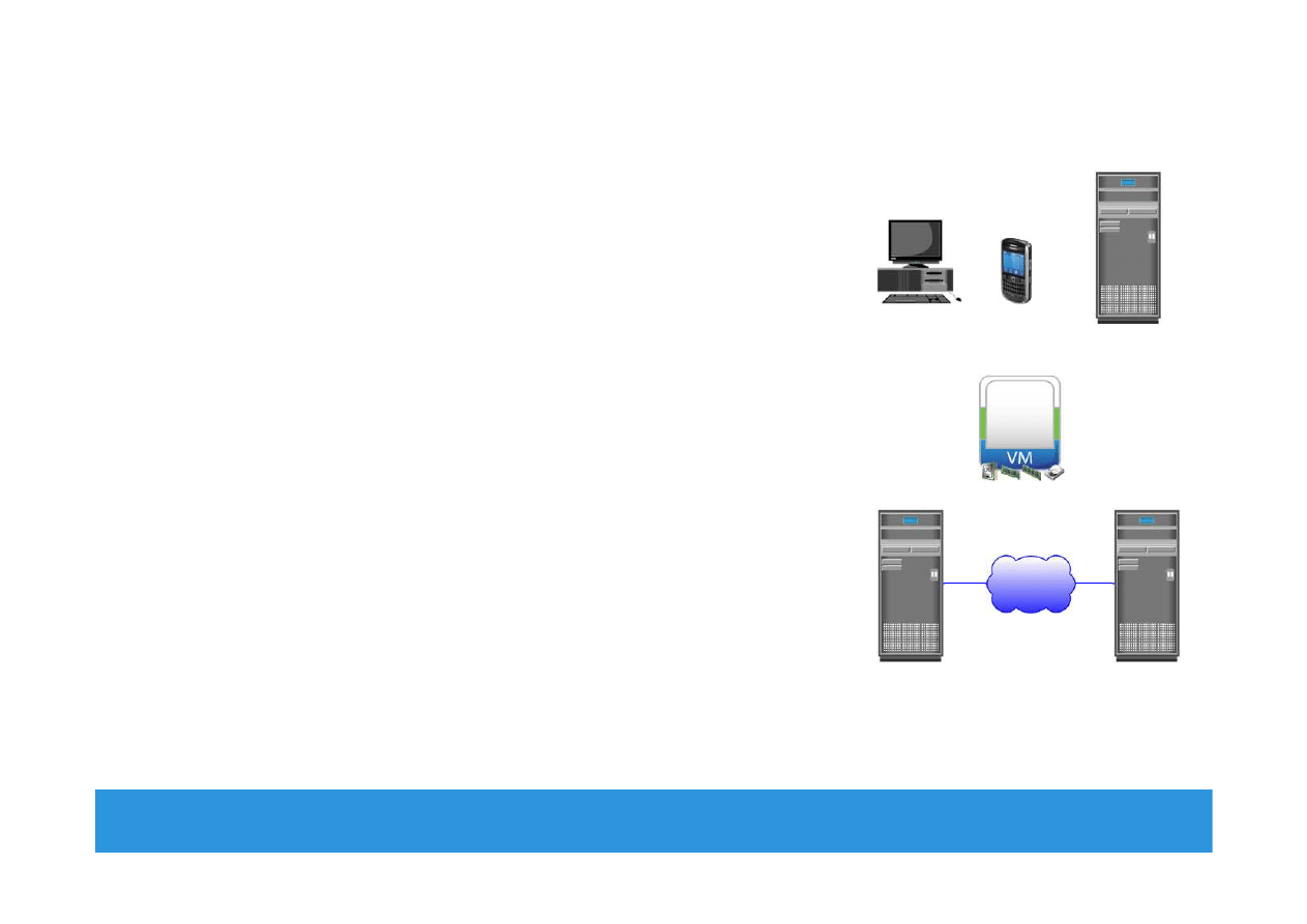
Host (Compute)
•
Resource that runs applications with the
help of underlying computing
components
Example: Servers, mainframes, laptop,
desktops, tablets, server clusters, etc.
•
Consists of hardware and software
components
•
Hardware components
Include CPU, memory, and input/output
(I/O) devices
•
Software components
Include OS, device driver, file system,
volume manager, and so on
Module 2: Data Center Environment
7
IP

EMC Proven Professional
. Copyright © 2012 EMC Corporation. All Rights Reserved
.
Operating Systems and Device Driver
•
In a traditional environment OS resides between the applications
and the hardware
Responsible for controlling the environment
•
In a virtualized environment virtualization layer works between
OS and hardware
Virtualization layer controls the environment
OS works as a guest and only controls the application environment
In some implementation OS is modified to communicate with
virtualization layer
•
Device driver is a software that enables the OS to recognize the
specific device
Module 2: Data Center Environment
8
EMC Proven Professional
. Copyright © 2012 EMC Corporation. All Rights Reserved
.
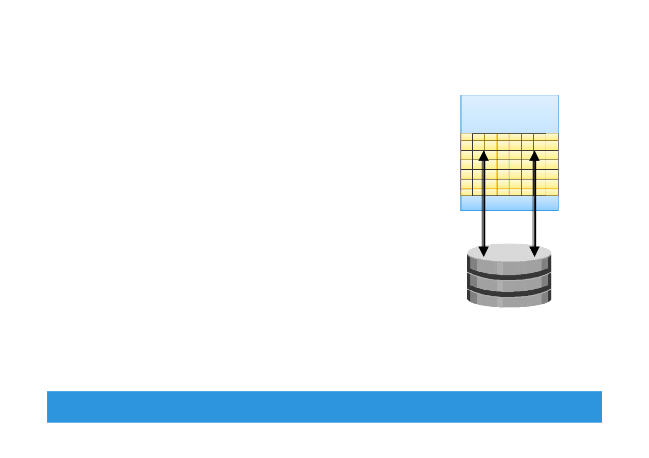
Memory Virtualization
•
An OS feature that presents larger memory to
the application than physically available
Additional memory space comes from disk
storage
Space used on the disk for virtual memory is
called ‘swap space/swap file or page file’
Inactive memory pages are moved from
physical memory to the swap file
Provides efficient use of available physical
memory
Data access from swap file is slower – use of
flash drives for swap space gives best
performance
Module 2: Data Center Environment
9
Operating System
Memory
Swap in
Swap out
Disk Drive
EMC Proven Professional
. Copyright © 2012 EMC Corporation. All Rights Reserved
.
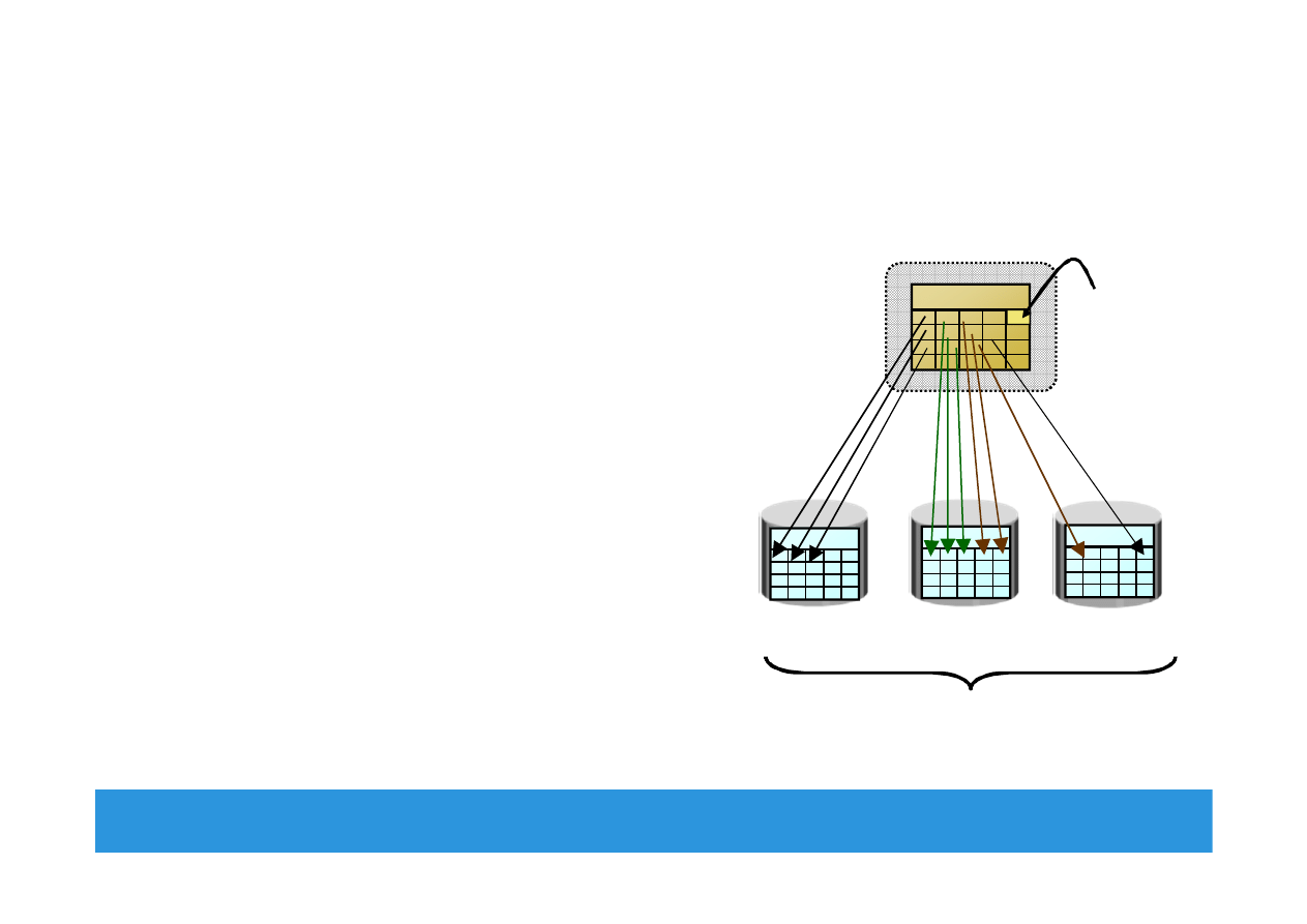
Logical Volume Manager (LVM)
•
Responsible for creating and
controlling host level logical storage
Physical view of storage is converted
to a logical view
Logical data blocks are mapped to
physical data blocks
•
One or more Physical Volumes form
a Volume Group
LVM manages Volume Groups as a
single entity
•
Logical volumes are created from the
volume group
Module 2: Data Center Environment 10
Logical Disk
Block
Volume Group
Physical Vol. 2
Physical Vol. 3
Logical Volume
Logical Volume
Physical Vol. 1
EMC Proven Professional
. Copyright © 2012 EMC Corporation. All Rights Reserved
.
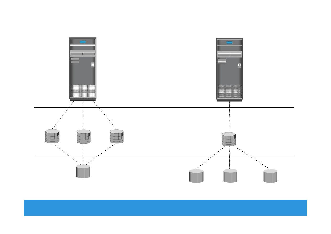
LVM Example: Partitioning and Concatenation
Module 2: Data Center Environment 11
Partitioning
Concatenation
Logical Volume
Physical Volume
Hosts
EMC Proven Professional
. Copyright © 2012 EMC Corporation. All Rights Reserved
.
File System
Module 2: Data Center Environment 12
1
2
3
4
5
6
Mapped to
Mapped to
Users
Files
File System
File System Blocks
LVM Logical Extents
Disk Physical
Extents
Disk Sectors
Creates/
Manages
Mapped to
Reside in
Mapped to
EMC Proven Professional
. Copyright © 2012 EMC Corporation. All Rights Reserved
.
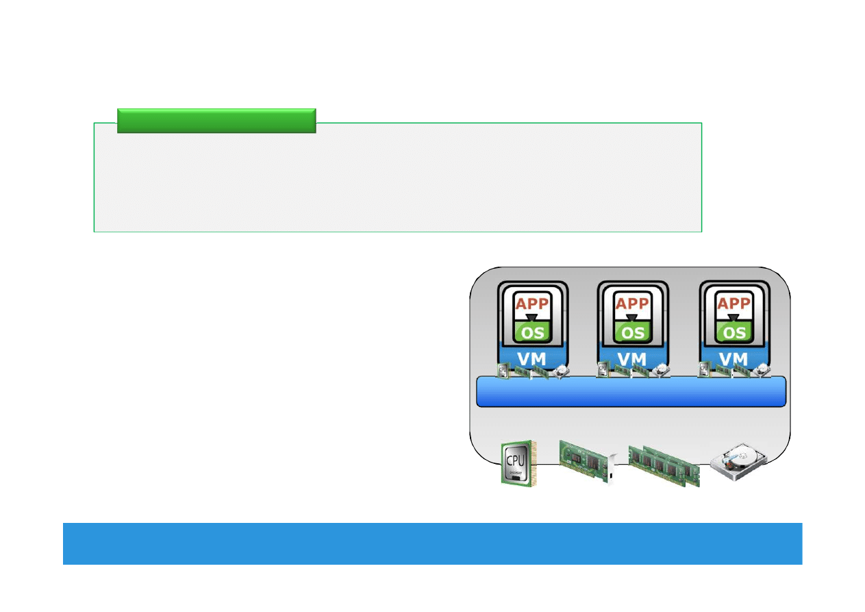
Compute Virtualization
Module 2: Data Center Environment 13
•
Enables creation of multiple virtual
machines (VMs), each running an OS
and application
VM is a logical entity that looks and
behaves like physical machine
•
Virtualization layer resides between
hardware and VMs
Also known as hypervisor
•
VMs are provided with standardized
hardware resources
It is a technique of masking or abstracting the physical compute
hardware and enabling multiple operating systems (OSs) to run
concurrently on a single or clustered physical machine(s).
Compute Virtualization
CPU
Memory
NIC Card
Hard Disk
Virtualization Layer (Hypervisor)
x86 Architecture
EMC Proven Professional
. Copyright © 2012 EMC Corporation. All Rights Reserved
.
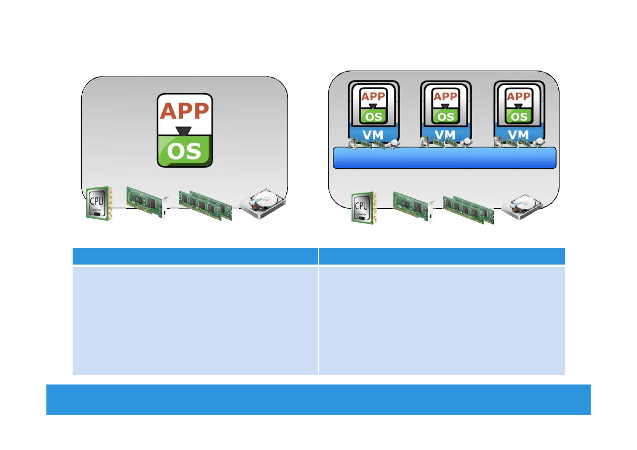
Need for Compute Virtualization
Module 2: Data Center Environment 14
Before Virtualization
After Virtualization
•
Runs single operating system (OS) per
machine at a time
•
Couples s/w and h/w tightly
•
May create conflicts when multiple applications
run on the same machine
•
Underutilizes resources
•
Is inflexible and expensive
•
Runs multiple operating systems (OSs) per
physical machine concurrently
•
Makes OS and applications h/w independent
•
Isolates VM from each other, hence, no conflict
•
Improves resource utilization
•
Offers flexible infrastructure at low cost
x86 Architecture
CPU
Memory
NIC Card
Hard Disk
CPU
Memory
NIC Card
Hard Disk
Virtualization Layer (Hypervisor)
x86 Architecture
EMC Proven Professional
. Copyright © 2012 EMC Corporation. All Rights Reserved
.
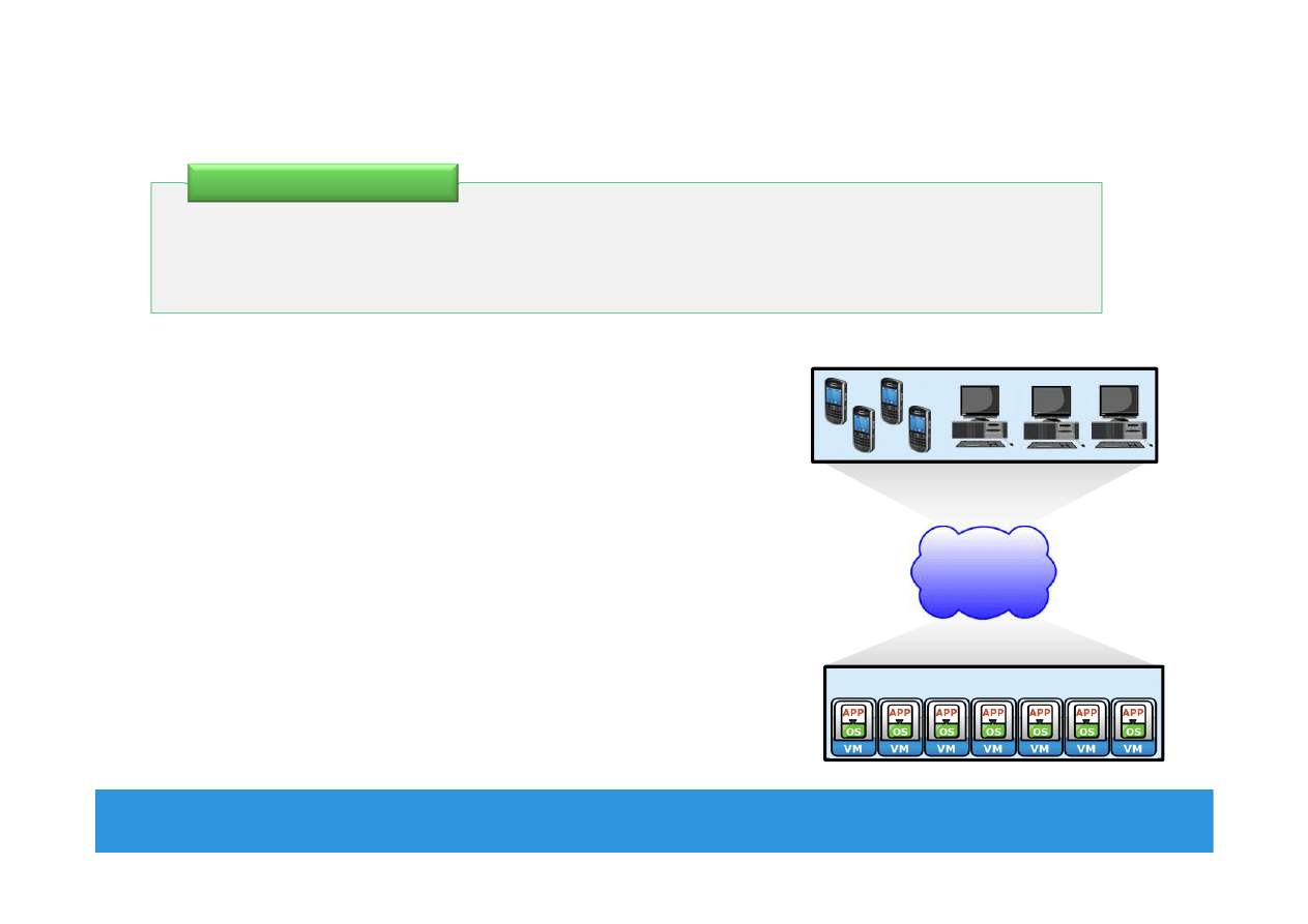
Desktop Virtualization
Module 2: Data Center Environment 15
•
Enables organizations to host and
centrally manage desktops
Desktops run as virtual machines within the
data center and accessed over a network
•
Desktop virtualization benefits
Flexibility of access due to enablement of
thin clients
Improved data security
Simplified data backup and PC maintenance
It is a technology which enables detachment of the user state, the
Operating System (OS), and the applications from endpoint devices.
Desktop Virtualization
LAN/WAN
Desktop VMs
Pcs and thin clients

EMC Proven Professional
. Copyright © 2012 EMC Corporation. All Rights Reserved
.
Module 2: Data Center Environment
During this lesson the following topics are covered:
•
Physical components of connectivity
•
Storage connectivity protocols
Lesson 2: Connectivity
Module 2: Data Center Environment 16
EMC Proven Professional
. Copyright © 2012 EMC Corporation. All Rights Reserved
.
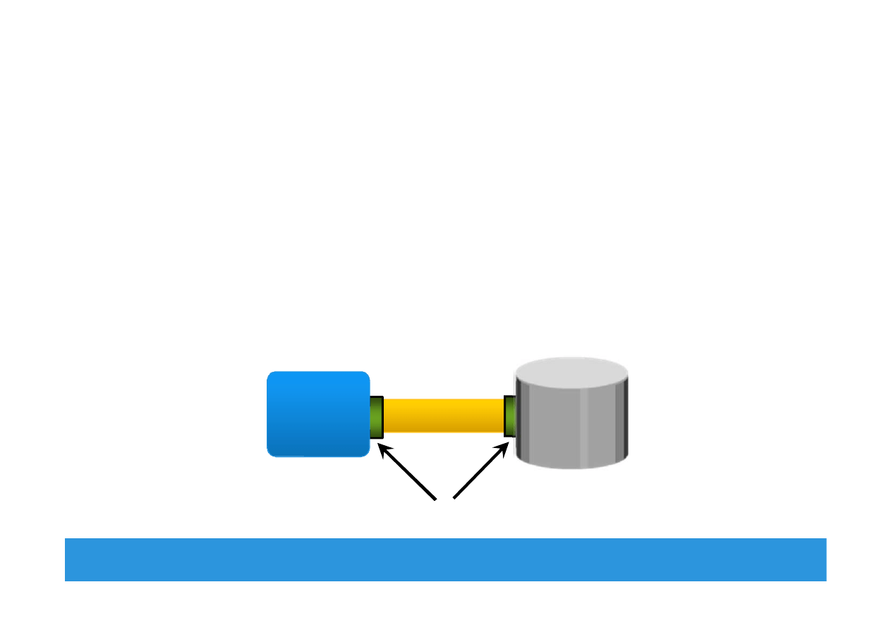
Connectivity
•
Interconnection between hosts or between a host and
peripheral devices, such as storage
•
Physical Components of Connectivity are:
Host interface card, port, and cable
•
Protocol = a defined format for communication between sending
and receiving devices
Popular storage interface protocols: IDE/ATA and SCSI
Module 2: Data Center Environment 17
Host
Adapter
Port
Cable
Disk

EMC Proven Professional
. Copyright © 2012 EMC Corporation. All Rights Reserved
.
IDE/ATA and Serial ATA
•
Integrated Device Electronics (IDE)/Advanced Technology
Attachment (ATA)
Popular interface used to connect hard disks or CD-ROM drives
Available with varity of standards and names
•
Serial Advanced Technology Attachment (SATA)
Serial version of the IDE/ATA specification that has replaced the
parallel ATA
Inexpensive storage interconnect, typically used for internal
connectivity
Provides data transfer rate up to 6 Gb/s (standard 3.0)
Module 2: Data Center Environment 18

EMC Proven Professional
. Copyright © 2012 EMC Corporation. All Rights Reserved
.
SCSI and SAS
•
Parallel Small computer system interface (SCSI)
Popular standard for connecting host and peripheral devices
Commonly used for storage connectivity in servers
Higher cost than IDE/ATA, therefore not popular in PC
environments
Available in wide variety of related technologies and standards
Support up to 16 devices on a single bus
Ultra-640 version provides data transfer speed up to 640 MB/s
•
Serial Attached SCSI (SAS)
Point-to-point serial protocol replacing parallel SCSI
Supports data transfer rate up to 6 Gb/s (SAS 2.0)
Module 2: Data Center Environment 19

EMC Proven Professional
. Copyright © 2012 EMC Corporation. All Rights Reserved
.
Fibre Channel and IP
•
Fibre Channel (FC)
Widely used protocol for high speed communication to the storage
device
Provides a serial data transmission that operates over copper wire
and/or optical fiber
Latest version of the FC interface ‘16FC’ allows transmission of
data up to 16 Gb/s
•
Internet Protocol (IP)
Traditionally used to transfer host-to-host traffic
Provide opportunity to leverage existing IP based network for
storage communication
Examples: iSCSI and FCIP protocols
Module 2: Data Center Environment 20

EMC Proven Professional
. Copyright © 2012 EMC Corporation. All Rights Reserved
.
Module 2: Data Center Environment
During this lesson the following topics are covered:
•
Various storage options
•
Disk drive components, addressing, and performance
•
Enterprise Flash drives
•
Host access to storage and direct-attached storage
Lesson 3: Storage
Module 2: Data Center Environment 21

EMC Proven Professional
. Copyright © 2012 EMC Corporation. All Rights Reserved
.
Storage Options
•
Magnetic Tape
Low cost solution for long term data storage
Preferred option for backup destination in the past
Limitations
Sequential data access
Single application access at a time
Physical wear and tear
Storage/retrieval overheads
Module 2: Data Center Environment 22

EMC Proven Professional
. Copyright © 2012 EMC Corporation. All Rights Reserved
.
Storage Options (contd.)
•
Optical discs
Popularly used as distribution medium in small, single-user
computing environments
Limited in capacity and speed
Write once and read many (WORM): CD-ROM, DVD-ROM
Other variations: CD-RW, Blu-ray discs
•
Disk drive
Most popular storage medium
Large storage capacity
Random read/write access
•
Flash drives
Uses semiconductor media
Provide high performance and low power consumption
Module 2: Data Center Environment 23
EMC Proven Professional
. Copyright © 2012 EMC Corporation. All Rights Reserved
.
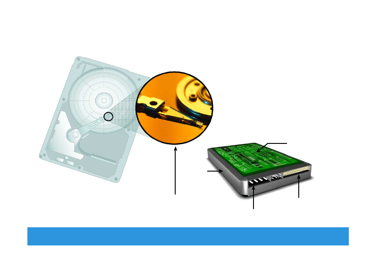
Disk Drive Components
Module 2: Data Center Environment 24
Interface
Controller
Board
Power
Connectors
HDA
Platter and
Read/Write Head
EMC Proven Professional
. Copyright © 2012 EMC Corporation. All Rights Reserved
.
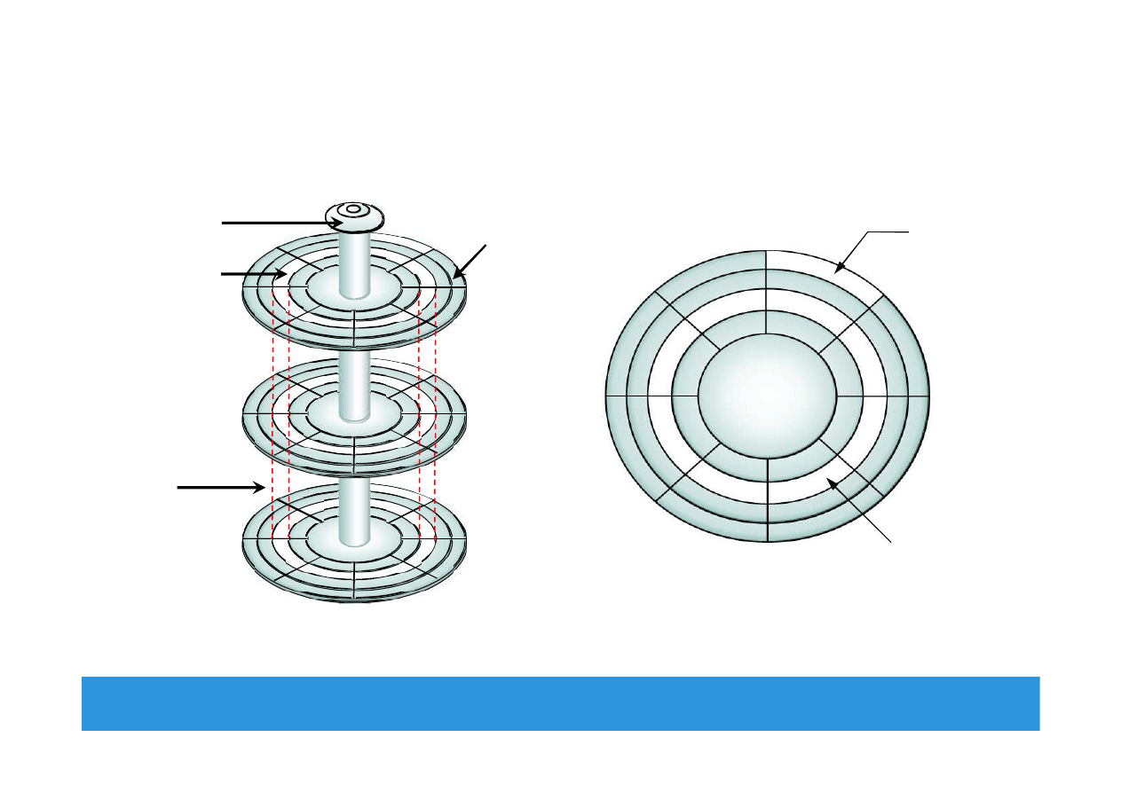
Physical Disk Structure
Module 2: Data Center Environment 25
Sector
Track
Platter
Sector
Track
Cylinder
Spindle
EMC Proven Professional
. Copyright © 2012 EMC Corporation. All Rights Reserved
.
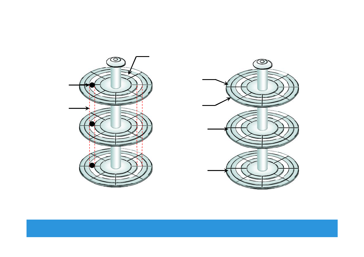
Logical Block Addressing
Module 2: Data Center Environment 26
Physical Address= CHS
Cylinder 1
Head 0
Sector 8
Block 64
Block 128
Logical Block Address= Block#
Block 0
Block 32
(Upper Surface)
(Lower Surface)

EMC Proven Professional
. Copyright © 2012 EMC Corporation. All Rights Reserved
.
Disk Drive Performance
•
Electromechanical device
Impacts the overall performance of the storage system
•
Disk service time
Time taken by a disk to complete an I/O request, depends on:
Seek time
Rotational latency
Data transfer rate
Disk service time = seek time + rotational latency + data transfer time
Module 2: Data Center Environment 27
EMC Proven Professional
. Copyright © 2012 EMC Corporation. All Rights Reserved
.
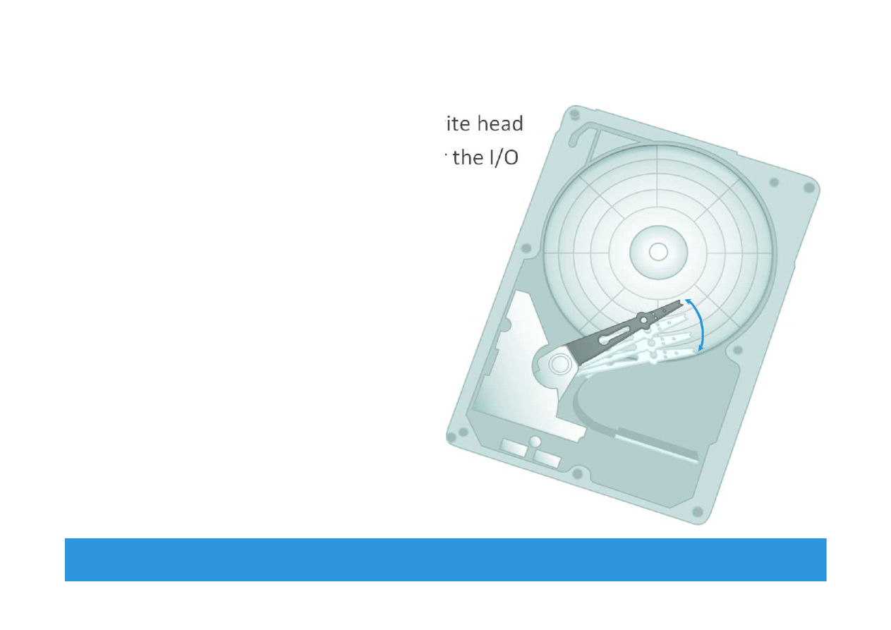
Seek Time
•
Time taken to position the read/write head
•
The lower the seek time, the faster the I/O
operation
•
Seek time specifications
include
Full stroke
Average
Track-to-track
•
The seek time of a disk is specified
by the drive manufacturer
Module 2: Data Center Environment 28
Radial
Movement
EMC Proven Professional
. Copyright © 2012 EMC Corporation. All Rights Reserved
.
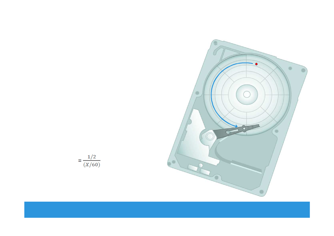
Rotational Latency
•
The time taken by the platter
to rotate and position the data
under the R/W head
•
Depends on the rotation speed
of the spindle
•
Average rotational latency
One-half of the time taken for
a full rotation
For ‘X’ rpm, drive latency is
calculated in milliseconds as:
Module 2: Data Center Environnent 29
EMC Proven Professional
. Copyright © 2012 EMC Corporation. All Rights Reserved
.
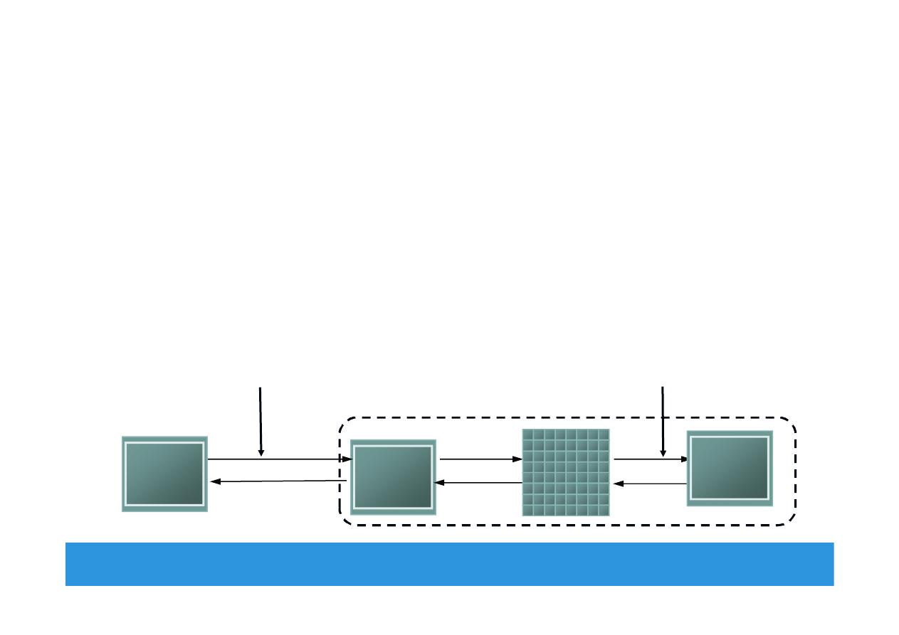
Data Transfer Rate
•
Average amount of data per unit time that the drive can deliver
to the HBA
Internal transfer rate : Speed at which data moves from a platter’s
surface to the internal buffer of the disk
External transfer rate: Rate at which data move through the
interface to the HBA
Module 2: Data Center Environment 30
Interface
Interface
Buffer
Buffer
HBA
HBA
Internal transfer rate
measured here
External transfer rate
measured here
Head Disk
Assembly
Head Disk
Assembly
Disk Drive
EMC Proven Professional
. Copyright © 2012 EMC Corporation. All Rights Reserved
.
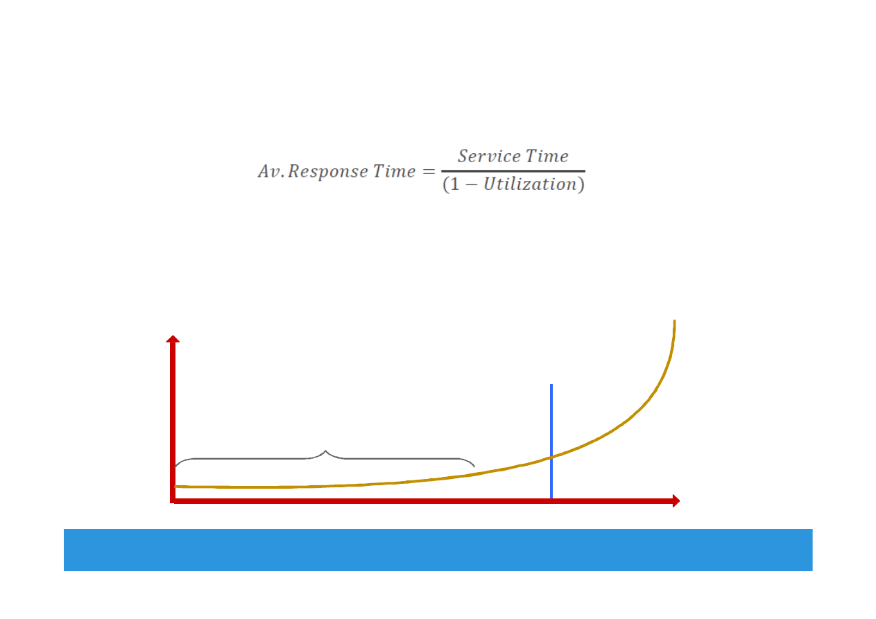
I/O Controller Utilization Vs. Response Time
•
Based on fundamental laws of disk drive performance:
Service time is time taken by the controller to serve an I/O
•
For performance-sensitive applications disks are commonly
utilized below 70% of their I/O serving capability
Module 2: Data Center Environnent 31
0%
100%
Utilization
Knee of curve: disks at
about 70% utilization
Low Queue Size
70%
R
e
sp
o
n
se
t
im
e
(
m
se
c)
EMC Proven Professional
. Copyright © 2012 EMC Corporation. All Rights Reserved
.
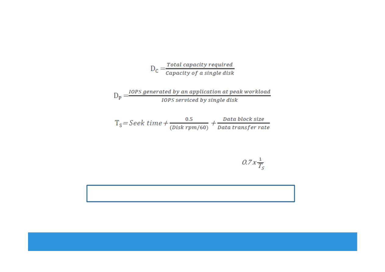
Storage Design Based on Application Requirements
and Disk Drive Performance
•
Disks required to meet an application’s capacity need (D
C
):
•
Disks required to meet application’s performance need (D
P
):
•
IOPS serviced by a disk (S) depends upon disk service time (T
S
):
T
S
is time taken for an I/O to complete, therefore IOPS serviced by
a disk (S) is equal to (1/T
S
)
For performance sensitive application (S)
=
Disk required for an application = max (D
C
,D
P
)
Module 2: Data Center Environnent 32

EMC Proven Professional
. Copyright © 2012 EMC Corporation. All Rights Reserved
.
Enterprise Flash Drives
Conventional Hard Drives
Flash Drives
Mechanical delay due to seek time and
rotational latency
Highest possible throughput per drive
due to no mechanical movement
Limited performance and I/O serving
capability
Very low latency per I/O and consistent
I/O performance
More power consumption due to
mechanical operations
High Energy efficiency
• Lower power requirement per
GB
• Lower power requirement per
IOPS
Low mean time between failure (MTBF)
High reliability due to no moving parts
Higher TCO due to more number of
disks, power, cooling, and management
cost
Overall less TCO
Module 2: Data Center Environment 33
EMC Proven Professional
. Copyright © 2012 EMC Corporation. All Rights Reserved
.
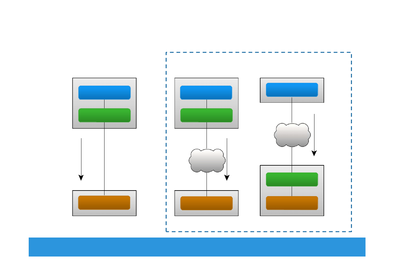
Host Access to Storage
Module 2: Data Center Environment 34
Network
Compute
Block-level
Request
Block-level Access
File-level
Request
Storage
System
Compute
File-level Access
Compute
Block-level
Request
Direct-Attached Storage
Storage Networking Options
Application
File System
Storage
Application
File System
Application
Storage
File System
Storage
Storage
Network
Storage
Network
EMC Proven Professional
. Copyright © 2012 EMC Corporation. All Rights Reserved
.
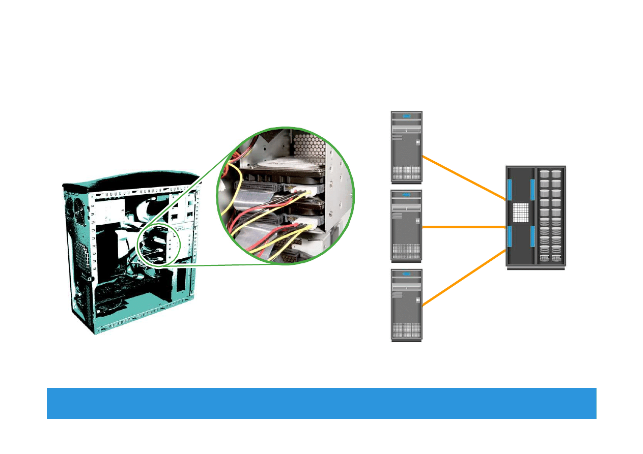
Direct-Attached Storage (DAS)
Module 2: Data Center Environment 35
Internal Direct Connect
External Direct Connect

EMC Proven Professional
. Copyright © 2012 EMC Corporation. All Rights Reserved
.
Module 2: Data Center Environment
•
VMware ESXi
Concept in Practice
Module 2: Data Center Environment 36

EMC Proven Professional
. Copyright © 2012 EMC Corporation. All Rights Reserved
.
VMware ESXi
•
Industry’s leading hypervisor
Enable virtualization of x86 hardware platforms
•
Physical machine that houses ESXi is called ESXi host
ESXi host abstracts physical compute resources to run multiple
VMs concurrently on same physical server
•
Two Components
VMKernel
Work similar to OS – responsible for process creation, resource
scheduling, and so on
Virtual machine monitor
Performs binary translation for privileged OS instructions that can
not be virtualized
Module 2: Data Center Environment 37

EMC Proven Professional
. Copyright © 2012 EMC Corporation. All Rights Reserved
.
Module 2: Summary
Key points covered in this module:
•
Key data center elements
•
Application and compute virtualization
•
Disk drive components and performance
•
Enterprise flash drives
•
Host access to storage
Module 2: Data Center Environment 38

EMC Proven Professional
. Copyright © 2012 EMC Corporation. All Rights Reserved
.
Exercise: Design Storage Solution for New
Application
•
Scenario
Characteristics of new application:
Require 1TB of storage capacity
Peak I/O workload 4900 IOPS
Typical I/O size is 4KB
Specifications of the available disk drives:
15K rpm drive with storage capacity = 100 GB
Average seek time = 5ms
Data transfer rate = 40 MB/sec
As it is business critical application, response time must be within
acceptable range
•
Task
Calculate the number of disks required for the application
Module 2: Data Center Environment 39
Wyszukiwarka
Podobne podstrony:
Module 02
Assertivness Module 02
CE Elementary module 02 web worksheet
02 cisco semestr 3 v31 module 2 exam
02 cisco semestr 2 v31 module 2 exam
02 BS Module 1 Section 2
Wyk 02 Pneumatyczne elementy
02 OperowanieDanymiid 3913 ppt
02 Boża radość Ne MSZA ŚWIĘTAid 3583 ppt
OC 02
PD W1 Wprowadzenie do PD(2010 10 02) 1 1
02 Pojęcie i podziały prawaid 3482 ppt
WYKŁAD 02 SterowCyfrowe
więcej podobnych podstron