
VER 100 YEARS OF DESIGN AND
analysis of electric machinery has been ac-
complished by those specializing in power
systems, machinery, power electronics, and
motor drives [1]. In the last decade, micromachining tech-
nology has enabled the use of small sensors and actuators in
microelectromechanical systems (MEMS) [2]. One cate-
gory of actuators is the micromotor—an electric motor
with a diameter on the order of 1 mm (different criteria can
apply). Most work in this field is by semiconductor-fabri-
cation specialists who generally do not have expertise in
machine design and control. This article gives a perspec-
tive on micromotors from the vantage point of the electric
drive specialty.
Micromotors are not currently being widely used in
industrial applications but are in a developmental
stage that suggests a near-future explosion of applica-
tions. For example, biomedical applications, such as
drug delivery systems [2], surgical tools [3], and
p r o b e s [ 4 ] , a r e c o n s i d e r e d v e r y p r o m i s i n g .
Micromotors can be used in optical systems in inte-
grated circuits (ICs) for various purposes [5].
Compared to linear actuators that might be more easily
fabricated, the rotary micromotor provides unlimited
movement in one axis. Thus, it is important for the
drives community to contribute to this field. This arti-
cle contains an analysis and literature review that
might be helpful towards this end.
62
1077-2618/03/$17.00©2003 IEEE
IEEE
IN
DU
ST
RY
A
PPLI
C
A
TI
O
NS
MA
GA
ZI
NE
•
J
A
N
|FEB
2003
•
WWW.
IEEE.
ORG/I
A
S
Perspectives on
MICROMOTORS
and ELECTRIC
DRIVES.
B Y P A T R I C K L .
C H A P M A N &
P H I L I P T . K R E I N
O
©COMSTOCK
Fundamental Scaling
Energy Density
While magnetic motors dominate macroscale applica-
tions, electrostatic machines have been clearly favored for
microscale. Why is this? Mainly, it is due to limitations in
current micromachining practices, but we will show that
there are fundamental reasons behind the use of
electrostatics. Attainable energy density has commonly
been considered a figure of merit that yields an extreme ad-
vantage for electrostatic micromachines over magnetic [7],
[8]. However, this was before the advent of several en-
abling technologies for magnetic motors, such as lithogra-
phy, electroplating, and replication by injection molding
(LIGA) [9] and the microfabrication of permanent mag-
nets (PMs) [10].
Energy density in an electric field at any point in a lin-
ear, isotropic region is given by
W
E
E
=
0 5
2
.
,
ε
(1)
where
ε
is the permittivity of the material at the given
point and E is the electric field. Likewise, magnetic field
energy density is given at any point in a linear, isotropic re-
gion by
W
B
M
=
0 5
2
.
,
µ
(2)
where
µ
is the magnetic permeability and B is the flux den-
sity magnitude.
The assumption of linearity is valid for air-gap fields.
This is the main consideration here since the bulk of the en-
ergy stored is in the air gap. Furthermore, gap length is a
reasonable measure of the precision of the fabrication pro-
cess used. Any nonlinearity that is present outside the air
gap will affect the results in an incremental manner.
Ferromagnetic materials cannot ordinarily exceed about
1.5 T without saturation. Since some motors, such as
switched reluctance machines, routinely operate saturated,
a fair estimate of the maximum useful flux density is 2 T.
Due to the space required for conductors, flux becomes
twice as concentrated in some areas (such as in stator teeth),
and the air-gap flux density is usually effectively limited to
1 T. For these reasons, 1 T will be taken as the typical, max-
imum flux density to be considered.
Dielectric breakdown voltage, which is about 3 MV/m
in air for large gaps, is a fundamental limit for electrostatic
energy storage. Substitutions into (1) and (2) show that en-
ergy densities of about 400 kJ/m
3
and 40 J/m
3
for mag-
netic and electrostatic energy storage, respectively, are
attainable in air. The numbers support the assertion that
magnetic motors are most viable in the macroscale.
However, the same relationships do not follow on the
microscale. In [7], the major factor cited in favor of electro-
static motors is the increase in electric field breakdown
strength as gap distance decreases. This relationship is gov-
erned by the empirical relationship known as Paschen’s
Law [11]:
( )
( )
[
]
E
p
pd
B
=
+
100
365
118
.
ln
,
(3)
where p is the pressure in Torr, and d is the gap distance in
centimeters. The breakdown field, E
B
, is in V/m. The fac-
tor of 365 is a unit-conversion ratio. The formula has a sin-
gularity at about 4
µ
m, corresponding to about 10
9
V/m.
Direct field emission initiates at about this field intensity,
even in vacuum. It should be noted that electric fields and
ionic flows are understood at dimensions below 4
µ
m, but
Paschen’s Law is a sound basis for comparison if the field
intensity is held to a limit of 10
9
V/m.
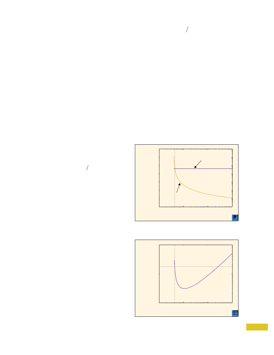
If (3) is substituted into (1), a revised estimate of the
attainable energy density results. This relationship is
plotted versus gap distance in Fig. 1. In the figure, the
dashed line represents the estimate of maximum mag-
netic field energy density, assuming a 1-T field is attain-
able for all d. The electrostatic energy density outpaces
that of the magnetic below 5
µ
m. Also, notice that the
electric energy density is considerably greater than 40
J/m
3
throughout the range of interest.
63
IEEE
IN
D
U
STRY
APPLI
C
ATI
O
NS
MAGAZI
NE
•
J
AN|F
E
B
2003
•
WWW.I
EEE.ORG/I
A
S
10
8
10
6
10
4
10
2
10
−
6
10
−
5
10
−
4
10
−
3
Gap Length (m)
Energy
(J/m )
3
Best Case
Magnetic (1 T)
Best Case
Paschen’s Electric
Comparison of energy density with Paschen’s Law in-
cluded.
108
106
104
102
10
−
6
10
−
5
10
−
4
10
−
3
Gap Length (m)
Energy
(J/m )
3
Best Case
Magnetic (1 T)
Best Case
Paschen’s Electric
1
10
4
10
3
10
2
10
−
6
10
−
5
10
−
4
10
−
3
Gap Length (m)
Voltage
(V)
Voltage required to produce maximum energy density for
electric fields.
104
103
102
10
−
6
10
−
5
10
−
4
10
−
3
Gap Length (m)
Voltage
(V)
2
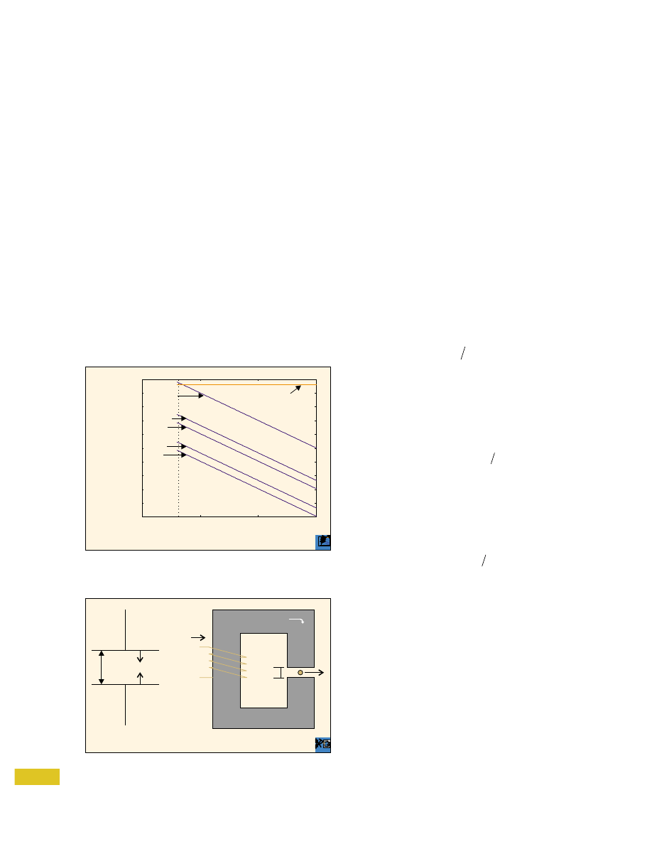
Before concluding that electrostatic devices have a tre-
mendous edge, notice that it was assumed in Fig. 1 that the
breakdown field would be achieved. The voltage required
to reach the breakdown field is depicted in Fig. 2. In the
4-5
µ
m regime, upwards of 1,500 V is required. Clearly
this is a shortcoming, as voltages on that order are not ordi-
narily available on ICs. This problem is exacerbated when
considering that the motor is to be electronically driven,
thereby requiring highly capable power-electronic compo-
nents. If these power-electronic components are discrete
and external to the substrate, this defeats the idea of build-
ing a fully integrated microsystem.
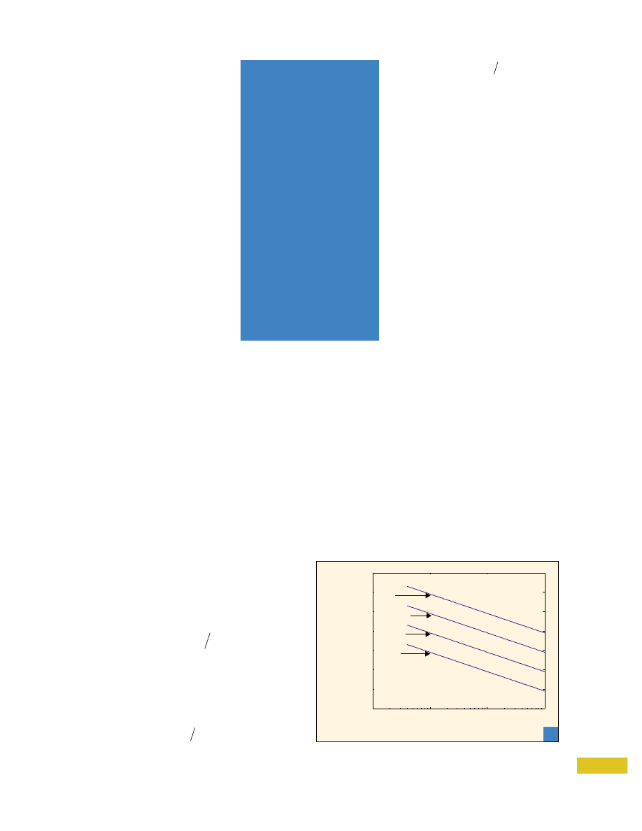
Supposing that the voltage is fixed at levels more typi-
cal for ICs, the energy density data is recomputed and
shown in Fig. 3. The energy density, for a 5-V logic level
drive is a much more modest 7 J/m
3
. Even with a 100-V
drive (optimistic, considering the highest voltage, fully-
IC drive reported thus far is 80 V [12]), about 6.3
×
10
5
J/m
3
is attainable—about 100 times lower than sug-
gested in Fig. 1. At this voltage, for 5-
µ
m gaps, the en-
ergy density is comparable to the maximum attained
magnetically.
This last point suggests that using Paschen’s Law for
scaling limits is moot in light the values of reasonably us-
able voltages. In other words, the electrostatic micro-
motor design is constrained as much by available operating
voltage as by breakdown voltage.
So far, the comparison to magnetic designs is not quite
equitable, since a 1-T flux-density condition—a limita-
tion imposed by saturation—was assumed to exist at all
length scales. It is important to determine whether this
restriction is realistic, or if a more conservative approach
is warranted.
Suppose the magnetic field intensity must be produced
by current carrying conductors. In this case, the maximum
energy density is limited by thermal considerations. For
example, the maximum current density in copper is about
1
×
10
7
A/m
2
. We define the sample geometries shown in
Fig. 4 in order to proceed. In the electrostatic case, we can
use a parallel-plate capacitance with plate spacing d. For
the magnetic case, the analog is an inductor with an air gap
d. In either case, the region of interest for this discussion is
the gap. It is recognized that the gap volume is only some
portion of the total actuator and associated circuitry in ei-
ther case. This is discussed below.
The flux density can be approximated by neglecting
fringing and considering that the reluctance is dominated
by air [1]
( )
R
d
A
i
=
µ
,
(4)
In (4), A
i
is the cross-sectional area of the magnetic
loop. When fringing is neglected, the expression yields a
lower reluctance than what is practical since most micro-
fabricated magnetic devices to date are planar. The total
flux is then
Φ =
=
BA
Ni R
i
,
(5)
where i is the current carried by the wire and N is the effec-
tive number of turns. The total current, Ni, can be treated
as a current density, J, integrated over the surface area of
the wire, A
w
. Then the flux density is derivable from (4)
and (5);
B
JA
d
w
= µ
,
(6)
where A
i
does not appear.
In (6), A
w
must be specified. For the sake of comparison,
assume that 1 T is achieved for a given gap of 10
µ
m and
the maximum current density of 1
×
10
7
A/m
2
. Neglecting
fill factor, the area of the wire required is about 8
×
10
−
7
m
2
, which is equivalent to a square with sides of 900
µ
m.
Therefore, the wire alone will probably cause the diameter
of the motor to exceed the 1-mm micromotor benchmark.
For miniaturization of the overall device, this does not
bode well for magnetic implementations, particularly
since the assumptions regarding fill factor and fringing fa-
vored the magnetic case.
Another obstacle is not the theoretical limit, but the
practical limit imposed by what is reasonable to accom-
plish on an IC. Continuing with the 10-
µ
m gap example,
the Ni product is about 8 A. In macroscale machines, the
current in an individual wire is kept low by using a large
64
IEEE
IN
D
U
STRY
APPLI
C
ATI
O
NS
MAGAZI
NE
•
J
AN|F
E
B
2003
•
WWW.I
EEE.ORG/I
A
S
10
6
10
4
10
2
10
−
6
10
−
5
10
−
4
10
−
3
Gap Length (m)
Energy
(J/m )
3
10
0
10
−
2
10
−
4
1,500 V
100 V
50 V
10 V
5 V
Electric
Energy
Densities,
Fixed
V
Best Case
Magnetic (1 T)
Comparison of electric and magnetic energy density when
voltage is fixed.
106
104
102
10
−
6
10
−
5
10
−
4
10
−
3
Gap Length (m)
Energy
(J/m )
3
100
10
−
2
10
−
4
1,500 V
100 V
50 V
10 V
5 V
Electric
Energy
Densities,
Fixed
V
Best Case
Magnetic (1 T)
3
d
F
V
i
B
N
d
F
+
−
Basic electric (left) and magnetic (right) geometries for
gap calculations.
d
F
V
i
B
N
d
F
+
−
4
N. In the literature [13], [14], only
small numbers of turns (
<
20) have been
thus far reported in prototype magnetic
micromotors. This is due to the present
limitations of fabricating these devices.
An easily obtainable current level for
ICs might be about 1 mA, which corre-
sponds to the thermal limit of a 5-
µ
m
trace. Consider N
=
10; then Ni is 10
mA and far less than the required 8 A.
Plots for various currents at N
=
10 are
shown in Fig. 5, which shows that much
more modest energy densities are ob-
tainable with a constrained number of
turns.
The use of PMs aids magnetic micro-
machines considerably. Permanent-
magnet machines have now been theo-
rized or reported in several instances
[15]-[18]. In this case, a fixed field
would be attainable down to small gaps,
the magnitude of which would depend
principally on the residual field of the
magnet rather than on thermal limita-
tions. The 1-T flux density assumption
used before would be appropriate.
Force Density
To this point, only the relative energy densities have been
considered. Perhaps of equal interest is the force that can be
produced. Referring to Fig. 4, in a uniform magnetic flux
density field B, a conductor of length L carrying a constant
current I, experiences a force
F
ILB
=
.
(7)
Current density can be substituted; divide by the volume
to obtain the volume-force density in the gap,
F
JB
v
=
.
(8)
The force density is then limited by the thermal capacity of
the conductor and the saturation field strength. For a 1-T
field, this gives 1
×
10
7
N/m
3
.
For the electrostatic case, a reasonable test case is that of
a parallel plate capacitor (Fig. 4). Here, the energy can be
expressed as
( ) ( )
W
A
Ed
d
E
p
= ε
2
2
,
(9)
where A
p
is the area of the plates. By co-energy theory [1],
this can be differentiated with respect to d to give the force.
Thereafter, divide by the volume to determine the volu-
metric force density
( )
F
E
d
v
= −ε
2
2
.
(10)
Alternatively, this can be expressed in terms of voltage
F
V
d
v
= −
05
2
3
.
.
ε
(11)
From (11), it is readily observed that
for a given voltage, this force density in-
creases dramatically as distance de-
creases. The crossover gap distance can be
determined by equating (8) and (11) for a
1-T field at maximum current density
and maximum electric field. The inter-
section occurs at 4
µ
m (12 V). Below this
gap distance, the electrostatic force den-
sity should be able to exceed the mag-
netic in all cases, given the assumed
physical constraints.
Overall Sizing and Design
Considerations
Overall miniaturization requires aspects
other than energy and force density to be
considered. Realistically, the gap is only
a fraction of the total size of the motor;
external excitation geometry and elec-
tronics must be considered. In each case,
the gap is small compared to the rotor di-
ameter. Since the electrostatic machine
achieved higher force density, a smaller radius rotor is
probably usable for a given torque specification.
Consider that in (8), the area occupied by the wire is a
key parameter in the ability to generate flux. As stated, the
area required for wiring is a limitation of magnetic ma-
chines. Furthermore, in the model of Fig. 4, there is a sig-
nificant amount of permeable material required to direct
the flux through the gap. Alternatively, producing the re-
quired voltage across a capacitance is straightforward and
requires comparatively insignificant space: the dielectric
material, air, is contained in the gap itself. However, elec-
trostatic micromotors consist of more than just one gap,
thereby complicating the geometry. Imposing high alter-
nating voltages onto successive electrodes requires a signif-
icant amount of space. In [19], for example, the ratio of
total diameter to rotor diameter is 1.9:1.
65
IEEE
IN
D
U
STRY
APPLI
C
ATI
O
NS
MAGAZI
NE
•
J
AN|F
E
B
2003
•
WWW.I
EEE.ORG/I
A
S
10
8
10
4
10
−
6
10
−
5
10
−
4
10
−
3
Gap Length (m)
Energy
(J/m )
3
10
0
10
−
2
Current Levels,
10 Turns
1 A
100 mA
10 mA
1 mA
Comparison of magnetic energy density for different cur-
rents, 10-turn winding.
5
COMPARED TO
LINEAR
ACTUATORS
THAT MIGHT BE
MORE EASILY
FABRICATED, THE
ROTARY
MICROMOTOR
PROVIDES
UNLIMITED
MOVEMENT IN
ONE AXIS.
Of course, micromotors are electronically driven. The
space occupied for the control circuitry should also be con-
sidered; for example, a high-current device for driving in-
ductive loads would occupy greater area, although the
voltage rating is not necessarily high. Driving electrostatic
motors necessitates high-voltage devices with low current.
Without a detailed comparison, it is probably fair to as-
sume that the overall drive size will be similar for similar
power levels.
The fabrication of electrostatic micromotors is often
simpler than that of magnetic micromotors. While some
reports have been given of success in the “winding” of mag-
netic cores and implementing PMs, the processes are com-
plicated. Magnetic materials, such as Ni
x
Fe
y
(Permalloy)
or samarium cobalt may be required. By comparison, only
silicon and copper are required as the base constituents of
the electrostatic motor. The geometry is much simpler due
to the absence of windings.
Overall, for microscale applications (
< 1 mm), electro-
static machines are clearly favored. Improvements are still
necessary in the integration of high-voltage electronics for
driving capacitive loads. Even if some of the present obsta-
cles can be overcome for magnetic machines, the fundamen-
tal force density problem will remain. However, this does
not rule out magnetic machines for larger, higher power
MEMS. It is also interesting that the analysis was mainly
based on gap length, not overall diameter. Therefore, if a
small enough gap could be achieved for a large motor, the
electrostatic topologies might be capable of more force.
Mechanical Considerations
One obstacle frequently addressed in MEMS literature is
friction; as machines become smaller, friction intensifies
significantly [20]-[21]. Fabrication of an ordinary bearing
assembly is not yet possible, so most early designs settled
on a p-i-n assembly. This method has high friction and ec-
centricity, but is straightforward to build. Levitation has
been successfully implemented in some machines, albeit
with undesirable wobble [22]-[23]. Micromotors resting in
fluid for lubrication may be promising [24]. An interesting
alternative is presented in [19], in which a gas-lubricated
system is utilized. It enables more efficient high-speed oper-
ation. Given the geometry constraints, high-power opera-
tion may be most easily achievable through high-speed op-
eration. In this case, friction elimination is the key.
Thus far, only some testing of micromachines’ torque-
speed and dynamic mechanical characteristics has been
done [25]-[27]. This is, perhaps, an area where electric
drives expertise could be employed to a greater extent.
Motor Topologies
Given the difficulty of fabricating micromotors, it is reason-
able to assert that simple structures will be favored. No rotor
mechanism, other than just plain conductors or magnets,
has been reported. In the magnetic types, switched reluc-
tance motors originally prevailed [13]-[14], although PM
synchronous motors show more promise in light of the scal-
ing issues [15]-[18]. Each of these machines requires some
rotor-position feedback. There are other simple motor tech-
nologies that have not been investigated much. These in-
clude slotless rotor induction machines and hysteresis
motors. Both are asynchronous motors (they require no posi-
tion sensing) with no rotor windings. Thus far, only rela-
tively flat machines have been reported. This relates to
fabrication difficulties in making laminations to increase
the axial length of magnetic machines. Permanent-magnet
disk motors have promise in large-scale applications that
maintain a relatively flat design [18] and seem more natural
for microfabrication. The low inductance of small magnetic
machines favors high switching frequencies and, therefore,
high speed, which exacerbates the friction problem.
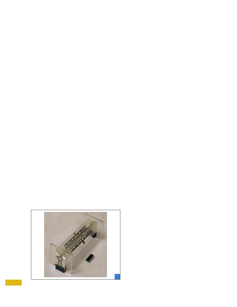
Successful electrostatic motors have been based on vari-
ous principles [28]-[30], including corona, varying capaci-
tance, harmonic drive, and charge induction. The latter is
perhaps most similar in principle to the typical slotless ro-
tor induction machine. The corona machine has the virtue
of being potentially self-levitating and is a “true” dc ma-
chine (Fig. 6). There is now a substantial body of literature
on design principles of these machines.
Since friction is a major issue, speed should be taken
into account. A machine with high pole count will operate
with proportionally higher torque and lower speed than
one with low pole count, although geometric complexity is
increased with additional poles. Currently, PM micro-
machines are limited to two-pole designs.
The control of micromotor drives [31]-[33] has only re-
cently been investigated and is certainly an area in which
drive expertise is needed. Much of the research in magnetic
induction motor drives can be adopted for electrostatic ma-
chines. Modeling of these machines is also a useful applica-
tion of a drive designer’s expertise [34].
Conclusion
Some fundamental constraints on the performance of micro-
motor technology have been discussed. Several aspects of
performance were explored, including energy density, force
density, size, constraints on motor-drive circuitry, motor to-
pologies, and friction. Analysis shows that electrostatic ma-
chines have advantages as microfabrication processes achieve
finer resolution, and, in fact, can exceed the energy and force
density capabilities of conventional magnetic machines at
small enough scales. Major thrusts for electric drive theory
to be applied are in control, topology optimization, and ma-
chine testing.
66
IEEE
IN
DU
ST
RY
A
PPLI
C
A
TI
O
NS
MA
GA
ZI
NE
•
J
A
N
|FEB
2003
•
WWW.
IEEE.
ORG/I
A
S
Example of a corona motor.
6

Acknowledgment
This work was supported by the Grainger Center for Electric
Machines and Electromechanics at the University of Illinois.
References
[1] P.C. Krause, O. Wasynczuk, and S.D. Sudhoff, Analysis of Electric
Machines. Piscataway, NJ: IEEE Press, 1996.
[2] N. Maluf, An Introduction to Microelectromechanical Systems. Norwood,
MA: Artech House, 2000.
[3] D. Polla, A. Erdman, D. Peichel, R. Rizq, Y. Gao, and D. Markus,
“Precision micromotor for surgery,” in Proc. 1st Int. Conf. Micro-
technologies in Medicine and Biology, 2000, pp.180-183.
[4] L.M. Gau, Y. Chen, L.M. Lin, and G.Z. Yan, “Micro motor based new
kind of endoscope,” in Proc. 20th Annu. Int. Conf. IEEE Engi-
neering in Medicine and Biology Society, 1998, vol. 4, pp. 1822-1825.
[5] A. Azzam Yasseen, S.W. Smith, F.L. Merat, and M. Mehregany, “Dif-
fraction grating scanners using polysilicon micromotors,” IEEE J.
Select. Topics Quantum Electron., vol. 5, pp. 75-82, Jan./Feb. 1999.
[6] B. Wagner, M. Kreutzer, and W. Benecke, “Linear and rotational
magnetic micromotors fabricated using silicon technology,” in
Proc. IEEE Micro Electromechanical Systems, 1992, pp. 183-189.
[7] S.F. Bart, T.A. Lober, R.T. Howe, J.H. Lang, and M.F. Schlecht, “De-
sign considerations for micromachined electric actuators,” Sens.
Actuators, vol. 14, no. 3, pp. 269-292, 1988.
[8] W.S.N. Trimmer and K.J. Gabriel, “Design considerations for a
practical electrostatic micro-motor,” Sens. Actuators, vol. 11, no. 2,
pp. 189-206.
[9] H. Guckel, “High-aspect ratio micromachining via deep X-ray li-
thography,” in Proc. IEEE Integrated Sensors, Microactuators, and
Microsystems, 1998, vol. 86, pp. 1586-1593.
[10] L.K. Lagorce and M.G. Allen, “Micromachined polymer magnets,”
in Proc. IEEE Micro Electromechanical Systems, 1996, pp. 89-90.
[11] J.D. Cobine, Gaseous Conductors. New York: Dover, 1958.
[12] P. Favrat, “A 1.5-V-supplied CMOS ASIC for the actuation of an
electrostatic micromotor,” IEEE/ASME Trans. Mechatron., vol. 2,
pp. 153-160, Sept. 1997.
[13] H. Guckel, T.R. Christenson, K.J. Skrobis, T.S. Jung, J. Klein, K.V.
Hartojo, and I. Widjaja, “A first functional current excited planar
rotational magnetic micromotor,” in Proc. IEEE Micro Electrome-
chanical Systems, 1993, pp. 7-11.
[14] C.H. Ahn, Y.J. Kim, and M.G. Allen, “A planar variable reluctance
magnetic micromotor with fully integrated stator and wrapped
coils,” J. MEMS, vol. 4, no. 2, pp. 165-173, 1993.
[15] K. Komori and T. Yamane, “Magnetically levitated micro PM mo-
tors by two types of active magnetic bearings,” IEEE/ASME Trans.
Mechatron., vol. 6, pp. 43-49, Mar. 2001.
[16] P.-A. Gilles, J. Delamare, O. Cugat, and J.-L. Schanen, “Design of a
permanent magnet planar synchronous micromotor,” in Conf. Rec.
IEEE IAS Annu. Meeting, 2000, vol. 1, pp. 223-227.
[17] A. Aguero, R. Moyano, and R. Cacace, “Application of rare earth
magnets in a micromotor,” in Proc. IEEE Int. Electric Machines and
Drives Conf., 1997, pp. MB2/7.1-MB2/7.3.
[18] A.M. Jungreis and A.W. Kelley, “The axial air gap wobble mo-
tor—An appropriate topology for magnetic micromotor,” in Conf.
Rec. IEEE IAS Annu. Meeting, 1995, pp. 781-788.
[19] L.G. Frechette, S.F. Nagle, R. Ghodssi, S.D. Umans, M.A. Schmidt,
and J.H. Lang, “An electrostatic induction micromotor supported
on gas-lubricated bearings,” in Proc. IEEE Int. Conf. Micro Electro
Mechanical Systems, 2001, pp. 290-293.
[20] L.S. Tavrow, S.F. Bart, and J.H. Lang, “Operational characteristics
of microfabricated electric motors,” in Int. Conf. on Solid-State Sen-
sors and Actuators. Dig. Tech. Papers, San Francisco, CA, 1991, pp.
877-881.
[21] R. Feynman, “Infinitesimal machines,” J. MEMS, vol. 2, no. 1, pp.
4-14, Mar. 1993.
[22] S. Kumar, D. Cho, and W. Carr, “A proposal for electrically levi-
tated micromotors,” Sens. Actuators A, Phys., vol. 24, no. 2, pp.
141-149, 1990.
[23] D.J. Alladi, M.L. Nagy, and S.L. Gaverick, “An IC for closed-loop
control of a micromotor with an electrostatically levitated rotor,” in
Proc. IEEE Int. Symp. Circuits and Systems, 1999, vol. 6, pp. 489-492.
[24] K. Deng, V.R. Dhuler, and M. Mehregany, “Measurement of
micromotor dynamics in lubricating fluids,” in Proc. IEEE Micro
Electro Mechanical Systems, 1993, pp. 260-264.
[25] V.D. Samper, A.J. Sangster, R.L. Reuben, and U. Wallrabe, “Torque
evaluation of a LIGA fabricated electrostatic micromotor,” J. MEMS,
vol. 8, no. 1, pp. 115-123, Mar. 1999.
[26] B.C. Kim and K. Marella, “A novel test methodology for MEMS
magnetic micromotors,” in Proc. 17th IEEE VLSI Test Symp., 1999,
pp. 284-289.
[27] W. Brenner, “The measurement of minimotors and micromotors
torque characteristic,” in Proc. 21st Int. Conf. Microelectronics, 1997,
vol. 2, pp. 535-538.
[28] M. Mehregany, S.F. Bart, L.S. Tavrow, J.H. Lang, S.D. Senturia, and
M.F. Schlecht, “A study of three microfabricated variable-capaci-
tance motors,” Sens. Actuators A, Phys., vol. 21, no. 1-3 2, part 2, pp.
173-179, 1990.
[29] P.T. Krein, “Analysis of corona motors and micromotors by means
of effective gap conductivity,” in Conf. Rec. 1991 IEEE-IAS Annu.
Meeting, pp. 555-561.
[30] W. Trimmer and R. Jebens, “Harmonic electrostatic motors,” Sens.
Actuators, vol. 20, no. 1-2, pp. 17-24, 1989.
[31] R. Di Stefano, F. Marignetti, and M. Scarano, “Optimal feeding of
an etched winding mini-motor,” in Proc. IEEE Int. Symp. Industrial
Electronics, 1997, pp. 474-479.
[32] A. Purushotham, S.L. Gaverick, C. Edwards, and M.L. Nagy, “A
closed-loop micromotor control system,” in Proc. IEEE Int. Symp.
Circuits and Systems, 1996, vol. 4, pp. 209-212.
[33] A. Kucukkomurler and S.L. Garverick, “Optimized step controller
for a salient-pole micromotor,” in Proc. IEEE Nat. Aerospace and
Electronics Conf., 2000, pp. 362-366.
[34] V. Fernandez, G. Reyne, and O. Cugat, “Prospective FEM modeling
of induction planar micromotors,” IEEE Trans. Magn., vol. 35, part
1, pp. 1805-1808, May 1999.
Patrick L. Chapman (chapman@ece.uiuc.edu) and Philip T.
Krein are with the University of Illinois at Urbana-Champaign
in Urbana, Illinois, USA. This article first appeared in its origi-
nal form at the 2001 IEEE IAS Annual Meeting.
67
IEEE
IN
DU
ST
RY
A
PPLI
C
A
TI
O
NS
MA
GA
ZI
NE
•
J
A
N
|FEB
2003
•
WWW.
IEEE.
ORG/I
A
S
Wyszukiwarka
Podobne podstrony:
mat fiz 2003 12 06 id 282350 Nieznany
2003 MAJ OKE PPid 21717 Nieznany
mat fiz 2003 10 11 id 282349 Nieznany
DzU 2003 089 0828 id 148548 Nieznany
BHP dz u 2003 47 401 id 84600 Nieznany (2)
mat fiz 2003 01 25 id 282348 Nieznany
mat fiz 2003 12 06 id 282350 Nieznany
2003 MAJ OKE PPid 21717 Nieznany
To Receive Is Better Michael Marshall Smith
Michael Marshall Smith To Receive Is Better
2003 08 what is a global manager
Which is better for the success of a civilization
IS 5 id 220327 Nieznany
IS wyklad 14 15 01 09 MDW id 22 Nieznany
IS OS c04 1 id 220342 Nieznany
Calki, IB i IS, 2011 12 id 1073 Nieznany
więcej podobnych podstron