1
INTRODUCTION
GENERAL
This section has the description and operation of the hy-
draulic brake system. The section also has repair proce-
dures for most of the components of the brake system.
Also see THE HYDRAULIC SYSTEM, 1900 SRM
471 or 1900 SRM 492 for more information on the hy-
draulic system.
These lift trucks have a hydraulic brake system. The
brake system uses the hydraulic fluid and several com-
ponents from the hydraulic system of the lift truck. The
main parts of the system are the hydraulic pump, accu-
mulator charge valve and accumulator, two pressure re-
duction valves and two brake pedal valves. For the ser-
vice brake system there are four brake calipers at the
drive wheels and an auxiliary caliper on the rotor on the
drive shaft. For the parking brake system there is a park-
ing brake valve, pilot valve and a caliper on the drive
shaft.
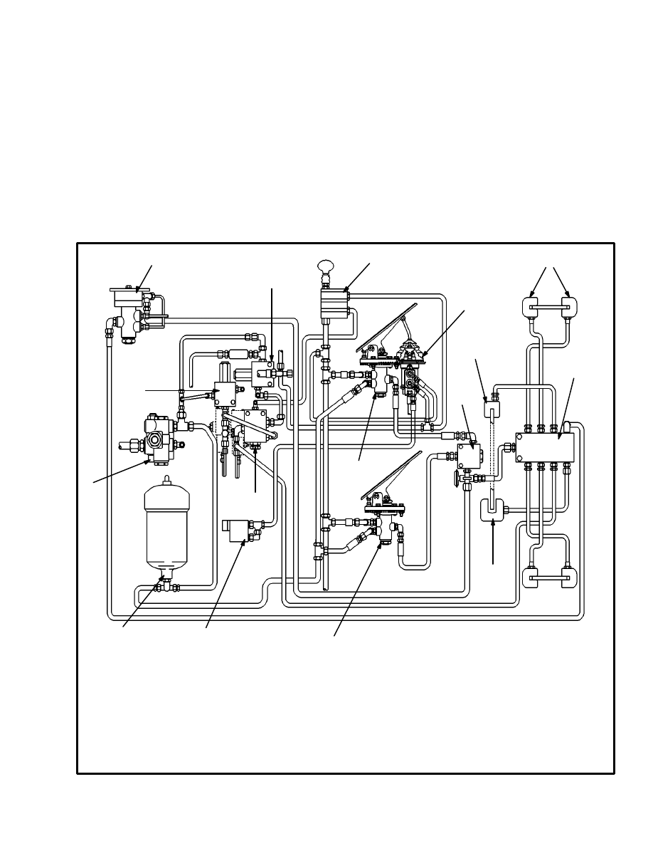
FIGURE 1. BRAKE SYSTEM DIAGRAM
1
2
3
4
5
6
7
8
9
10
11
12
13
14
15
16
1. ACCUMULATOR CHARGE VALVE
2. PRESSURE REDUCTION VALVE
10.3 MPa (1500 psi)
3. RELAY VALVE
4. PRESSURE REDUCTION VALVE
2.1 MPa (300 psi)
5. PARKING BRAKE VALVE
6. INCHING/BRAKE PEDAL VALVE
7. INCHING VALVE
8. SERVICE BRAKE CALIPERS
9. PARKING BRAKE CALIPER
10. SHUTTLE VALVE
11. MANIFOLD
12. AUXILIARY SERVICE BRAKE CALIPER
13. SERVICE BRAKE PEDAL VALVE
14. PILOT VALVE
15. INCHING SPOOLS (TRANSMISSION)
16. ACCUMULATOR
H36.00–48.00C SHOWN
H20.00–32.00F (H440–700F/FS) SIMILAR
2
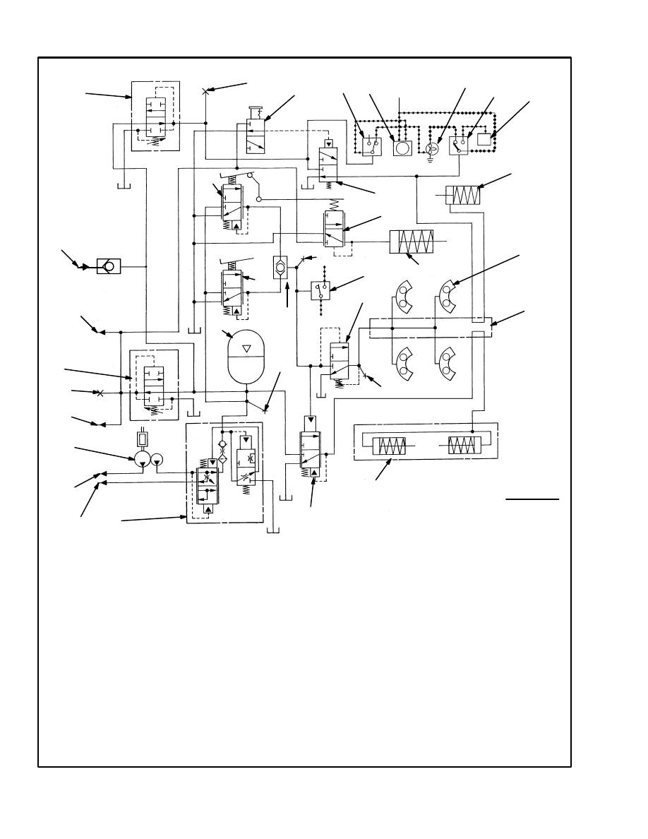
FIGURE 2. BRAKE SYSTEM SCHEMATIC, H20.00–32.00F (H440–700F/FS)
1. TANDEM HYDRAULIC PUMP
2. ACCUMULATOR CHARGE VALVE
3. PRESSURE REDUCTION VALVE
2.1 MPa (300 psi)
4. ACCUMULATOR
5. PRESSURE REDUCTION VALVE
10.3 MPa (1500 psi)
6. CHECK PORT NO. 3, 10.3 MPa (1500 psi)
7. PARKING BRAKE VALVE
8. INCHING/BRAKE PEDAL VALVE
9. INCHING VALVE
10. PILOT VALVE
11. LOW BRAKE PRESSURE SWITCH
12. LOW PRESSURE ALARM AND LIGHT
13. PARKING BRAKE LIGHT (APPLIED)
14. SWITCH, PARKING BRAKE PRESSURE
AND TRANSMISSION LOCK OUT
15. TRANSMISSION LOCK OUT
16. SERVICE BRAKE PEDAL VALVE
17. SHUTTLE VALVE
18. BRAKE LIGHT SWITCH
19. INCHING CYLINDER
20. PARKING BRAKE CALIPER
21. SERVICE BRAKE CALIPER
22. BRAKE MANIFOLD
23. SEQUENCE VALVE
24. AUXILIARY SERVICE BRAKE CALIPER
25. RELAY VALVE
26. TO LIFT CIRCUIT
27. TO STEERING CIRCUIT
28. TO ATTACHMENT CONTROL VALVE
29. CHECK PORT NO. 2, 2.1 MPa (300 psi)
30. TO REMOTE CONTROL VALVE
31. CHECK PORT NO. 4, 19.0 MPa (2750 psi)
32. CHECK PORT, 2.6 MPa (380 psi)
33. CHECK PORT, 13.8 MPa (2000 psi)
34. FROM BASE OF LIFT CYLINDERS
ELECTRICAL WIRE
• • • • • •
1
2
3
4
5
6
7
8
9
10
11
12
13
14
15
16
17
18
19
20
21
22
23
24
25
26
27
28
29
30
31
D
D
A
TT
HH
CC
V
EE
AA
MM (J)
NOTE: Letters by lines are identification codes.
Early production codes are in brackets.
FF
32
33
+ 24
VOLTS
34
3
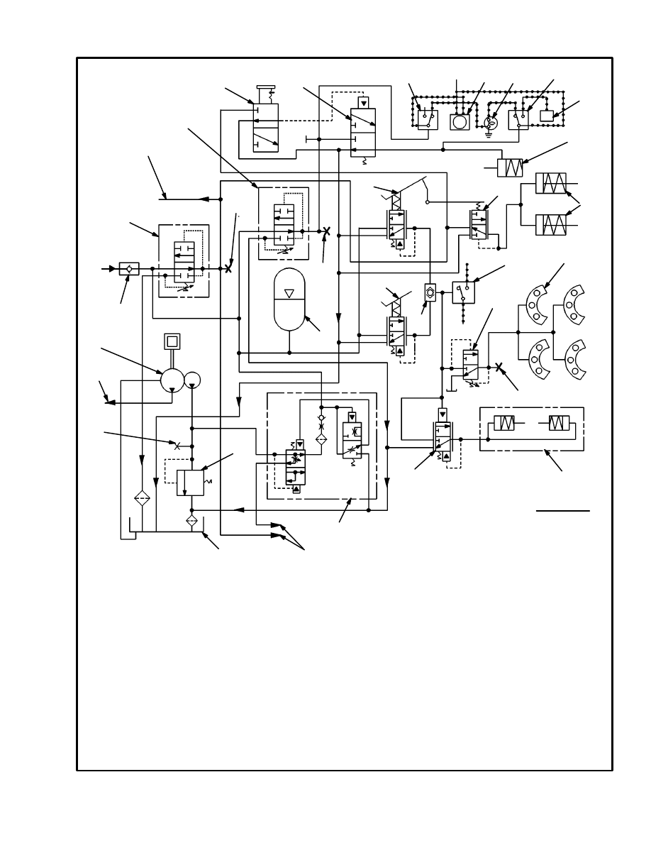
FIGURE 3. BRAKE SYSTEM SCHEMATIC, H36.00–48.00C (H800–1050C)
1. TANDEM HYDRAULIC PUMP
2. RELIEF VALVE
3. ACCUMULATOR CHARGE VALVE
4. CHECK VALVE
5. PRESSURE REDUCTION VALVE
2.1 MPa (300 psi)
6. ACCUMULATOR
7. PRESSURE REDUCTION VALVE
10.3 MPa (1500 psi)
8. PARKING BRAKE VALVE
9. PILOT VALVE
10. INCHING/BRAKE PEDAL VALVE
11. LOW BRAKE PRESSURE SWITCH
12. LOW PRESSURE ALARM AND LIGHT
13. PARKING BRAKE APPLIED LIGHT
14. SWITCH, PARKING BRAKE PRESSURE
AND TRANSMISSION LOCK OUT
1
2
3
4
5
7
8
10
24
9
11
12
13
14
15
16
17
18
19
20
23
22
25
15. TRANSMISSION LOCK OUT
16. PARKING BRAKE CALIPER
17. INCHING VALVE
18. INCHING SPOOLS (TRANSMISSION)
19. BRAKE LIGHT SWITCH
20. SERVICE BRAKE CALIPERS
21. SEQUENCE VALVE (LATE MODELS ONLY)
22. RELAY VALVE
23. AUXILIARY SERVICE BRAKE CALIPER
24. SERVICE BRAKE PEDAL VALVE
25. SHUTTLE VALVE
26. TO LIFT TRUCK HYDRAULIC SYSTEM
27. CHECK PORT, PRESSURE REDUCTION
VALVE, 2.1 MPa (300 psi)
27. CHECK PORT, PRESSURE REDUCTION
VALVE, 10.3 MPa (1500 psi)
28. HYDRAULIC TANK
29. CHECK PORT, ACCUMULATOR CHARGE
VALVE AND RELIEF VALVE
30. CHECK PORT, 2.6 MPa (380 psi)
ELECTRICAL WIRE
25
26
26
27
6
26
28
• • • • • •
21
29
+ 24V
30

4
DESCRIPTION AND OPERATION
H20.00–32.00F (H440–700F/FS)
(See FIGURE 1. and FIGURE 2.)
The small section of the tandem pump supplies the oil to
operate the brake system. Oil from the pump goes to the
accumulator charge valve. (Oil that is not needed by the
brake circuit flows to a control valve in the lift system.)
From the accumulator charge valve, oil flows to the ac-
cumulator, the pressure reduction valves and the brake
pedal valves. The accumulator stores oil to operate the
brakes when the engine is not running. The pressure re-
duction valve set at 2.1 MPa (300 psi) supplies oil to the
parking brake valve, inching valve and the remote con-
trol valve. The pressure reduction valve set at 10.3 MPa
(1500 psi) supplies oil to the pilot valve for the parking
brake caliper. There is a pressure switch connected to
this pressure reduction valve. Oil pressure holds the
switch open. When the oil pressure is less than (1300
psi), the switch closes, actuating the low pressure alarm
and light. The service brake pedal controls the flow of
oil to the service brakes. The inching brake pedal con-
trols the flow of oil to the service brakes and the inching
spool at the transmission.
DESCRIPTION AND OPERATION
H36.00–48.00C (H800–1050C)
(See FIGURE 1. and FIGURE 3.)
The small section of the tandem pump supplies the oil to
operate the brake system. Oil from the pump goes to a
relief valve and the accumulator charge valve. (Oil that
is not needed by the brake circuit flows to a control valve
in the lift system.) The relief valve is set at 22.1 MPa
(3200 psi). From the accumulator charge valve, oil
flows to the accumulator, the pressure reduction valves
and the brake pedal valves. The accumulator stores oil to
operate the brakes when the engine is not running. The
pressure reduction valve set at 2.1 MPa (300 psi) sup-
plies oil to the parking brake valve, inching valve and
the remote control valve. The pressure reduction valve
set at 10.3 MPa (1500 psi) supplies oil to the pilot valve
for the parking brake caliper. There is a pressure switch
connected to this pressure reduction valve. Oil pressure
holds the switch open. When the oil pressure is less than
(1300 psi), the switch closes, actuating the low pressure
alarm and light. The service brake pedal controls the
flow of oil to the service brakes. The inching brake pedal
controls the flow of oil to the service brakes and the
inching spools at the transmission.
ACCUMULATOR CHARGE VALVE
(See FIGURE 4.)
The accumulator charge valve controls the charging rate
and the pressure of the oil in the accumulator for the
brake system. This valve also supplies oil to the two
pressure reduction valves and the attachment control
valve.
The accumulator charge valve has a charging valve
spool, check valve and a pilot valve assembly. Oil from
the small section of the tandem pump enters the valve at
the charging valve spool. On the H36.00–48.00C
(H800–1050C) units a relief valve limits this oil to 22.1
MPa (3200 psi). Oil flows past the charging valve spool,
through a screen and past a check valve to the accumu-
lator and the pressure reduction valves. Oil also flows to
the attachment control valve. The accumulator charge
valve stops charging automatically when the accumula-
tor pressure reaches its high limit of 18.6 to 19.3 MPa
(2700 to 2800 psi). When the accumulator pressure
reaches its low limit of 14.1 to 14.8 MPa (2050 to 2150
psi), the accumulator charge valve allows oil from the
pump to charge the accumulator. Two check valves in
the circuit keep the oil from flowing out of the accumu-
lator.
When the accumulator is charged above its lower limit,
the charging valve spool is held against the stop by oil
that flows through the passage in the center of the spool.
While in this position, the charging valve spool allows
maximum flow to the control valve for the carriage and
attachment (H36.00–48.00C/H800–1050C) or the lift
system (H20.00–32.00F/H440–700F/FS). The check
ball for the lower limit is held on its seat by oil pressure
at the accumulator port.
When the pressure in the accumulator reaches its lower
limit, the pressure on the check ball for the lower limit
decreases and the check ball moves from its seat. At this
same time the pilot valve spool moves to let the check
ball for the upper limit to stop against its seat. (The pilot
valve spool permits only one of the check balls to be on
its seat at any time.) With the check ball for the lower
limit off its seat, pressure from the accumulator can flow
past the pilot valve spool. The oil then flows through an
orifice to the spring chamber for the charging valve
spool.
5
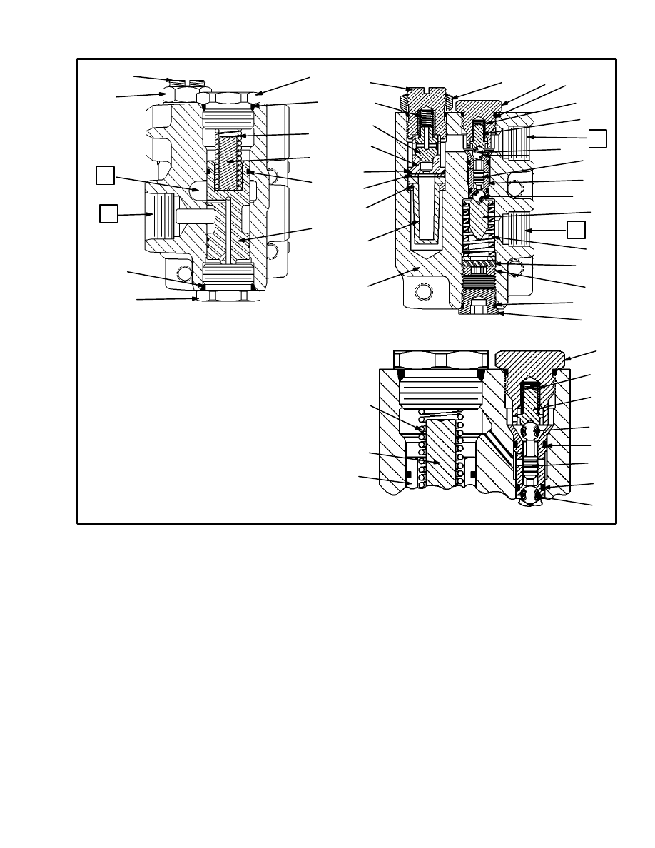
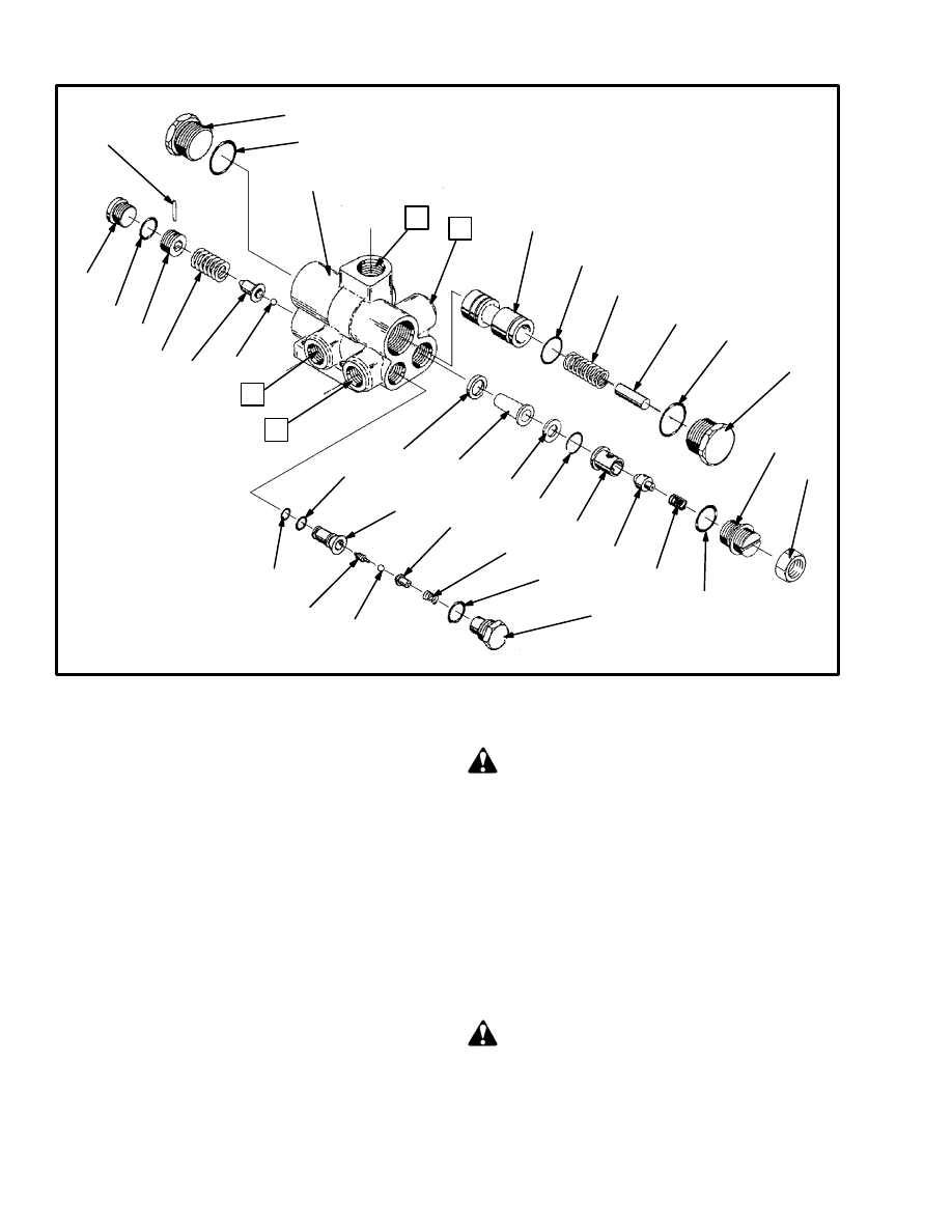
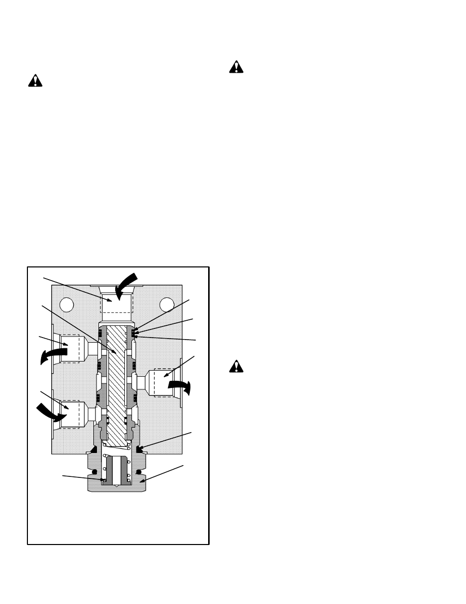
FIGURE 4. ACCUMULATOR CHARGE VALVE
1. PLUG
2. O–RING
3. PIN
4. SCREW
5. SPRING, PILOT
VALVE
6. BALL RETAINER
7. BALL, UPPER LIMIT
8. VALVE BODY
9. SPOOL, CHARGING
VALVE
10. SPRING
11. STOP
12. WASHER
13. FILTER
14. SEAT
15. CHECK VALVE
16. SPRING
17. SCREW ASSEMBLY
18. NUT
19. SLEEVE
20. SPOOL, PILOT
VALVE
21. BALL, LOWER LIMIT
22. SPRING
A=TO ACCUMULATOR
O=FLOW THROUGH
PORTS
17
18
O
2
1
9
2
11
10
2
1
1
22
6
2
A
20
19
7
6
T
5
3
4
2
1
13
12
12
17
16
2
14
15
18
1
6
22
21
20
2
2
7
10
11
9
P=INLET PRESSURE
T=TO DRAIN (TANK)
P
8
21
The oil pressure from the accumulator and the spring
push the charging valve spool against the pressure from
the inlet. The charging valve spool decreases the flow to
the control valve for the carriage and attachment
(H36.00–48.00C/H800–1050C) or the lift system
(H20.00–32.00F/H440–700F/FS), allowing the accu-
mulator to charge.
When the accumulator is charged to its upper limit, pres-
sure will move the check ball for the upper limit from its
seat. At the same time, the check ball for the lower limit
moves to its seat. When the check ball for the upper limit
is off its seat, the spring chamber for the charging valve
spool is open to the drain circuit. The charging valve
spool moves against the spring, allowing more oil to
flow to the control valve for the carriage and attachment.
When the operating pressure in the system is greater
than the pressure in the accumulator, the check valve
moves from its seat. Oil from the pump can flow directly
to and charge the accumulator, bypassing the charging
valve spool.
PRESSURE REDUCTION VALVES
(See FIGURE 8.)
There are two pressure reduction valves in the hydraulic
system. One of the pressure reduction valves controls
the flow of oil to the pilot circuits for the following: re-
mote control valve, the attachment control valve, the
parking brake valve and the inching control valve. This
pressure reduction valve limits the pressure in the pilot
circuits to 2.1 MPa (300 psi). The other pressure reduc-
tion valve limits the pressure to pilot valve for the park-
ing brake caliper to 10.3 MPa (1500 psi).
6
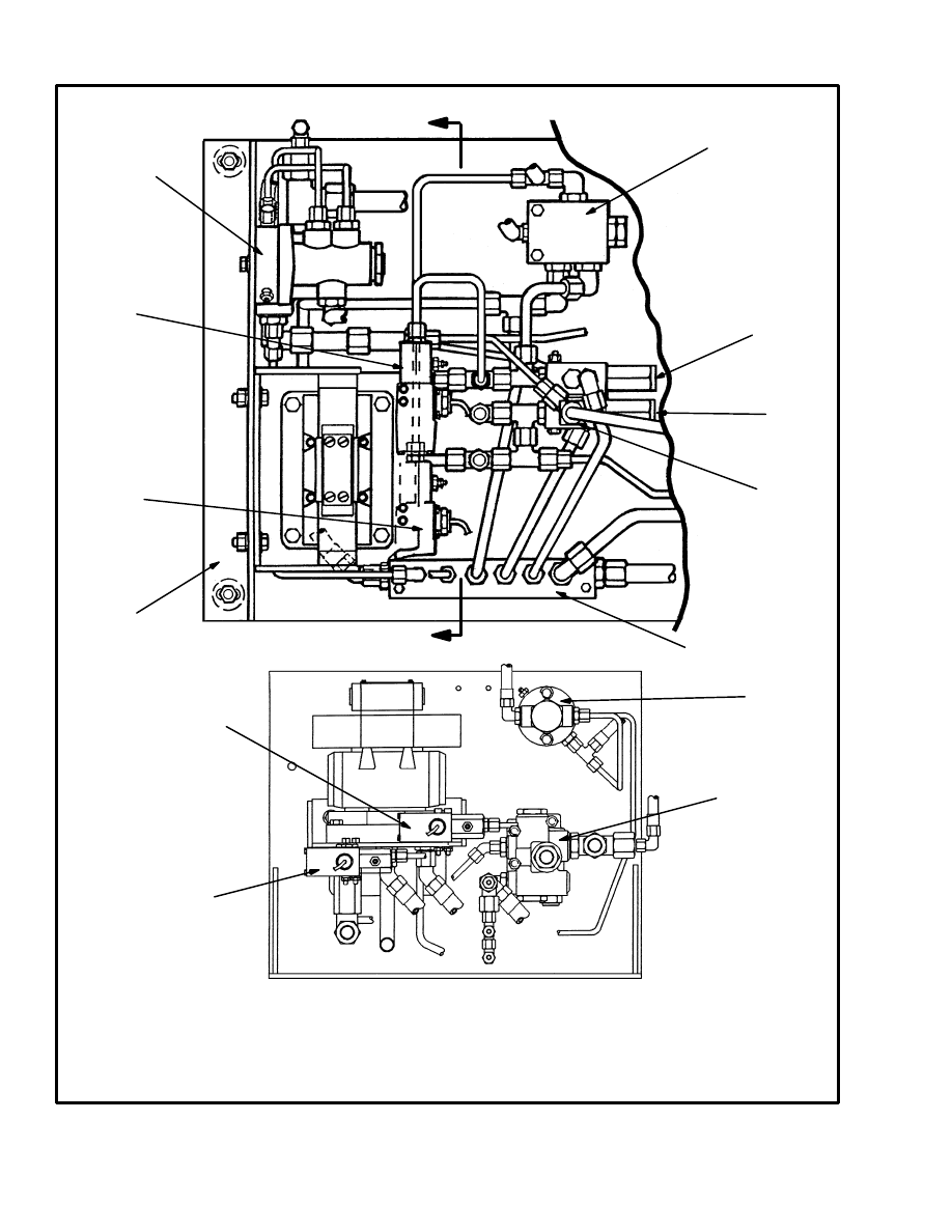
FIGURE 5. LOCATION OF BRAKE SYSTEM PARTS ON THE HYDRAULIC MODULE,
H20.00–32.00F (H440–700F/FS)
1. RELAY VALVE
2. PILOT VALVE
3. PRESSURE REDUCTION VALVE 10.3 MPa (1500 psi)
4. PRESSURE REDUCTION VALVE 2.1 MPa (300 psi)
5. CHECK VALVE
6. DRAIN MANIFOLD
7. PRESSURE SWITCH
8. PRESSURE SWITCH
9. ACCUMULATOR CHARGE VALVE
10. HYDRAULIC MODULE
VIEW A–A
A
A
1
2
3
4
6
7
8
5
1
9
8
7
10

7
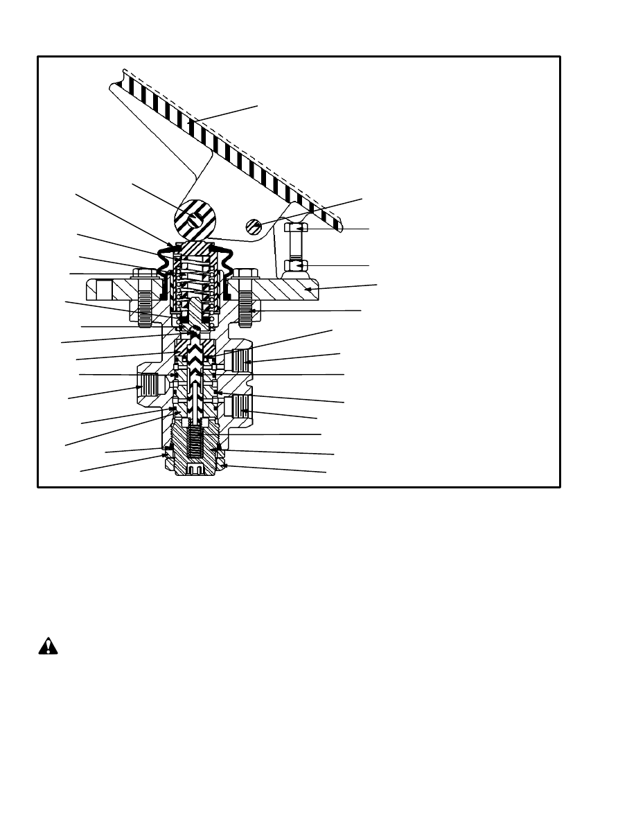
BRAKE PEDAL VALVES (See FIGURE 13.)
Operation, H20.00–32.00F (H440–700F/FS)
(See FIGURE 1. and FIGURE 2.)
The right–hand pedal operates only the service brakes
while the left–hand (inching/brake) pedal operates the
service brakes and the inching valve for the transmis-
sion. Both pedals can energize the brake pressure switch
on the shuttle valve to operate the stop lights.
When the right–hand pedal is depressed, hydraulic oil
flows through the pedal valve to the shuttle valve. From
the shuttle valve, oil flows to the sequence valve, service
brake calipers, relay valve and the auxiliary brake cali-
per. The operation of the sequence valve makes sure that
the service brake and auxiliary brake calipers apply at
the same time. Because of the springs in the auxiliary
caliper, approximately 2.6 MPa (380 psi) is required be-
fore the brake begins to apply. The sequence valve sup-
plies the auxiliary brake caliper (relay valve) with oil at
2.6 MPa (380 psi) and then opens to apply oil to the ser-
vice brakes at system pressure.The relay valve limits the
oil pressure to the auxiliary caliper to approximately
one–third of the oil pressure in the brake system. The
auxiliary caliper is installed on the differential housing
while its brake rotor is on the pinion shaft.
When the left–hand pedal is depressed, hydraulic oil
flows through the pedal valve to the brake calipers as de-
scribed for the right–hand pedal. The inching valve re-
ceives oil from a pressure reduction valve and is actu-
ated as the inching/brake pedal is depressed. The inch-
ing valve controls the oil flow to the inching cylinder. As
the inching/brake pedal is depressed, the transmission
begins to disengage and the service brakes are partially
applied. When the inching/brake pedal is fully de-
pressed, the transmission is completely disengaged and
the service brakes are applied. As the inching/brake ped-
al is released, the inching valve causes a decrease in oil
pressure to the service brakes. At the same time the oil
pressure to the inching cylinder decreases and the trans-
mission begins to engage.
Operation, H36.00–48.00C (H800–1050C)
(See FIGURE 1. and FIGURE 3.)
The right–hand pedal operates only the service brakes
while the left–hand (inching/brake) pedal operates the
service brakes and the inching valve for the transmis-
sion. Both pedals can energize the brake pressure switch
on the shuttle valve to operate the stop lights.
When the right–hand pedal is depressed, hydraulic oil
flows through the pedal valve to the shuttle valve. From
the shuttle valve, oil flows to the sequence valve (late
models only), service brake calipers and the relay valve.
The operation of the sequence valve makes sure that the
service brake and auxiliary brake calipers apply at the
same time. Because of the springs in the auxiliary cali-
per, approximately 2.6 MPa (380 psi) is required before
the brake begins to apply. The sequence valve supplies
the auxiliary brake caliper (relay valve) with oil at 2.6
MPa (380 psi) and then opens to apply oil to the service
brakes at system pressure. The relay valve limits the oil
pressure to the auxiliary caliper to approximately one–
third of the oil pressure in the brake system. The auxilia-
ry caliper is installed on the differential housing while
its brake rotor is on the pinion shaft.
When the left–hand pedal is depressed, hydraulic oil
flows through the pedal valve to the brake calipers as de-
scribed for the right–hand pedal. The inching valve re-
ceives oil from a pressure reduction valve and is actu-
ated as the inching/brake pedal is depressed. The inch-
ing valve controls the oil flow to the inching spools. As
the inching/brake pedal is depressed, the transmission
begins to disengage and the service brakes are partially
applied. When the inching/brake pedal is fully de-
pressed, the transmission is completely disengaged and
the service brakes are applied. As the inching/brake ped-
al is released, the inching valve causes a decrease in oil
pressure to the service brakes. At the same time the oil
pressure to the inching spools decreases and the trans-
mission begins to engage.
PARKING BRAKE (See FIGURE 18.)
The parking brake system uses a disc brake that is in-
stalled at the rear of the differential housing. The
spring–applied caliper is installed on the differential
housing while the brake rotor is on the pinion shaft.
The operation of the parking brake is controlled by the
parking brake valve. The valve is installed on the instru-
ment panel. The parking brake is applied when the knob
on the valve is pushed in. The parking brake is released
when the knob is pulled out. With the knob out, oil flows
from a pressure reduction valve at 2.1 MPa (300 psi)
through the parking brake valve to the pilot circuit of the
pilot valve. The pilot pressure moves the spool in the pi-
lot valve to let oil from the other pressure reduction
8
valve flow to the brake caliper. This oil (at 10.3 MPa
[1500 psi]) causes the brake caliper to open against the
spring pressure and release the parking brake.
There is a pressure switch connected to the pilot valve.
This switch actuates the light for the parking brake and
the transmission lock out relay. The switch is closed
(light illuminated) when the parking brake is applied (no
oil pressure). When the parking brake is released, oil
pressure opens the switch (light goes off) and energizes
the transmission lock out relay.
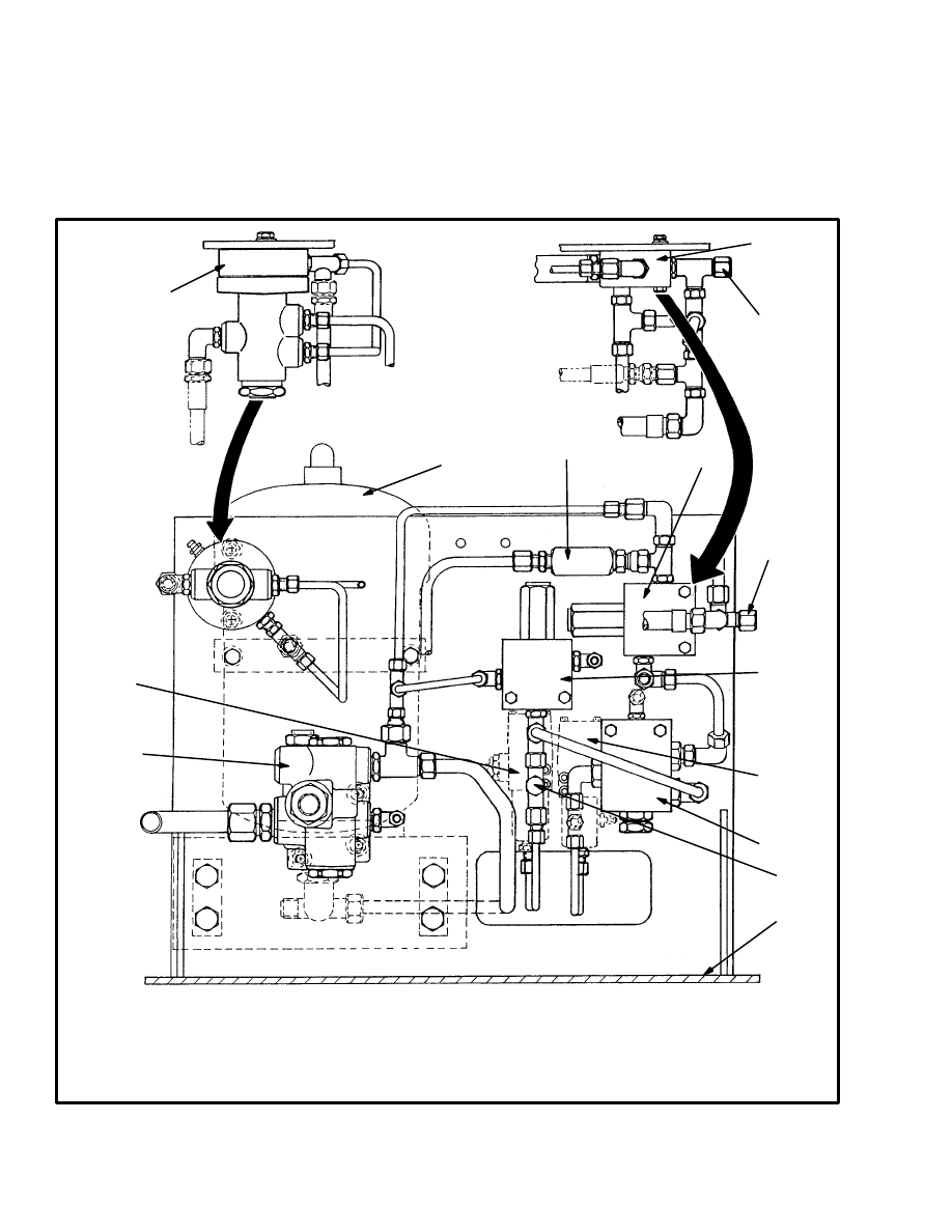
FIGURE 6. LOCATION OF BRAKE SYSTEM PARTS ON THE HYDRAULIC MODULE,
H36.00–48.00C (H800–1050C)
1
4
5
5
4
2
6
8
7
7
9
3
5
1. RELAY VALVE
2. ACCUMULATOR
3. CHECK VALVE
4. PRESSURE REDUCTION
VALVE, 2.1 MPa (300 psi)
8. PILOT VALVE
9. ACCUMULATOR CHARGE
VALVE
10. HYDRAULIC MODULE
10
5. CHECK PORT
6. PRESSURE REDUCTION
VALVE,10.3 MPa (1500 psi)
7. PRESSURE SWITCH (2)

9
REPAIRS
PRESSURE SWITCHES
(See FIGURE 5. and FIGURE 6.)
NOTE: The pressure switches are located on the mod-
ule with the hydraulic system components. The module
is on the left–hand side of the lift truck.
Replacement
(See FIGURE 5. and FIGURE 6.)
WARNING
Before disconnecting any hydraulic lines, release
pressure from the hydraulic circuit as follows:
a. Shut the engine off and completely lower the car-
riage.
b. Operate the lift/lower lever and the brake pedals
until the hydraulic pressure is released.
1. Put tags for identification on the lines. Disconnect the
lines from the switch. Put caps on the open lines. Re-
move the two capscrews that hold the switch to the mod-
ule. Remove the switch.
2. Install the new switch on the module. Connect the hy-
draulic lines and wire at the switch.
3. Remove the air from the hydraulic system and check
the pressure at the switch as described in CHECKS
AND ADJUSTMENTS.
ACCUMULATOR CHARGE VALVE
WARNING
Before disconnecting any hydraulic lines, release
pressure from the hydraulic circuit as follows:
a. Shut the engine off and completely lower the car-
riage.
b. Operate the lift/lower lever and the brake pedals
until the hydraulic pressure is released.
Removal and Disassembly
(See FIGURE 4., FIGURE 5., FIGURE 6.
and FIGURE 7.)
1. Put tags for identification on the lines. Disconnect the
lines from the valve. Put caps on the open lines. Remove
the valve from the module bracket.
2. Remove the plugs from the valve body one at a time.
Remove the parts from each bore and keep them togeth-
er. Before removing the screw (4), measure its depth in
the valve body. Make a note of this for assembly. To re-
move the screw (4), first pull the pin (3) from the valve
body, then remove the screw.
Cleaning and Inspection
WARNING
Cleaning solvents can be flammable and toxic, and
can cause skin irritation. When using cleaning sol-
vents, always follow the solvent manufacturer’s rec-
ommended safety precautions.
Clean the parts in solvent. Inspect the spools, springs
and bores for scratches. If there are scratches or other
damage, the parts must be replaced. Clean the filter.
Make sure the internal passages are clean. Lubricate the
parts with clean hydraulic oil for assembly.
Assembly and Installation
(See FIGURE 5., FIGURE 6. and
FIGURE 7.)
1. Do the following while assembling the parts in the
valve body as shown in FIGURE 7.
a. Tighten the screw assembly (17) to 24 to 30 N.m (18
to 22 lbf ft). Install the nut (18) and tighten it to 24 to 30
N.m (18 to 22 lbf ft).
b. Install the screw (4) until the hole in the screw is
aligned with the hole in the valve body. Check the
depth of the screw (4) with the measurement made
during disassembly. Install the pin (3) to keep the
screw in position. Install the O–ring and plug (1).
2. Install the valve on the bracket.
3. Connect the lines to the valve.
4. Operate the system and check the valve for leaks.
Adjustment (See FIGURE 7.)
After the accumulator charge valve is installed, check
the pressure settings.
1. Connect a 21 MPa (3000 psi) gauge to the check port
for the accumulator charge valve. This is check port No.
4 in the hydraulic compartment.
10
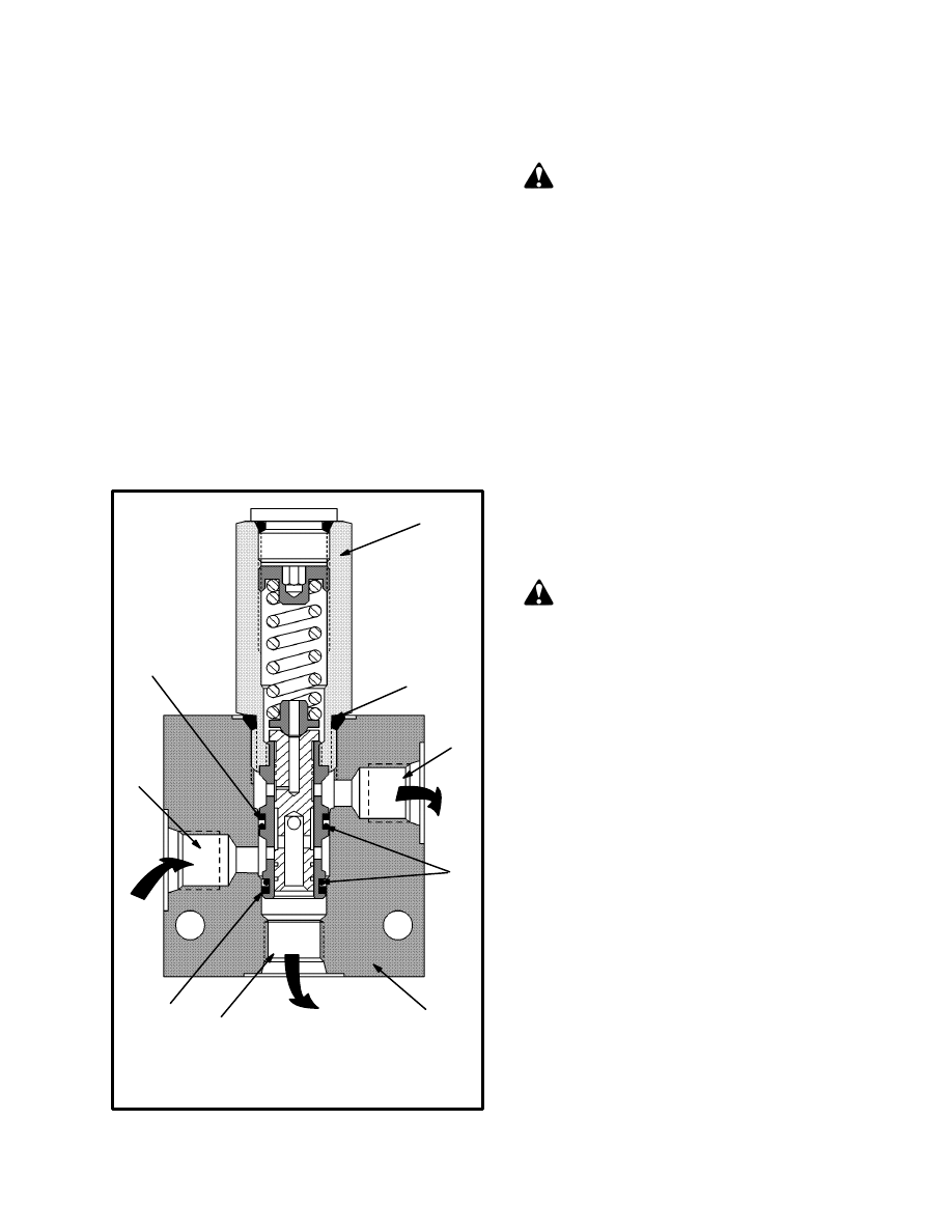
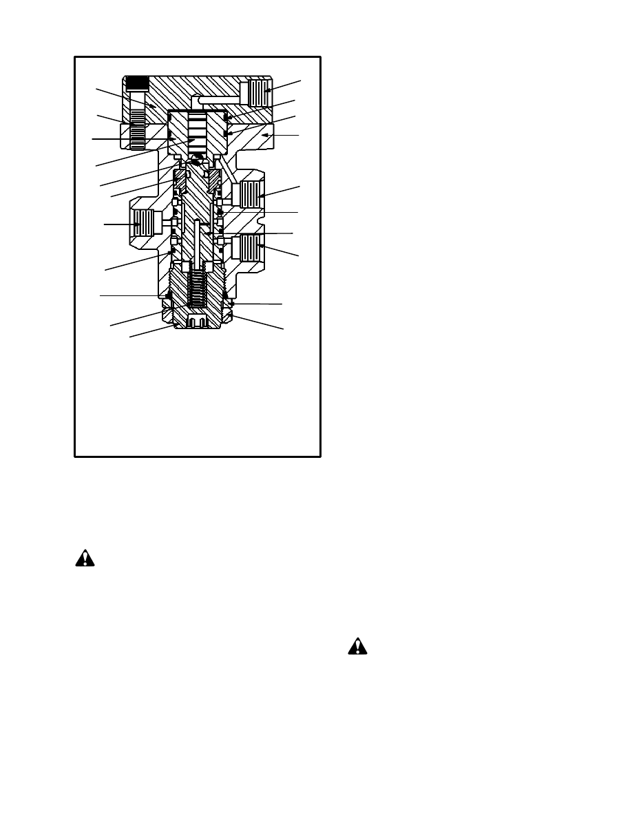
FIGURE 7. ACCUMULATOR CHARGE VALVE
1. PLUG
2. O–RING
3. PIN
4. SCREW
5. SPRING, PILOT VALVE
6. BALL RETAINER
7. BALL, UPPER LIMIT
8. VALVE BODY
9. SPOOL, CHARGING
VALVE
10. SPRING
11. STOP
12. WASHER
13. FILTER
14. SEAT
15. CHECK VALVE
16. SPRING
17. SCREW ASSEMBLY
18. NUT
19. SLEEVE
20. SPOOL, PILOT
VALVE
21. BALL, LOWER LIMIT
22. SPRING
1
2
3
1
2
4
5
6
7
8
9
2
10
11
2
1
17
18
12
13
12
2
14
15
16
2
2
19
2
20
21
1
2
22
6
PORTS
A=TO ACCUMULATOR
O=FLOW THROUGH
P=INLET PRESSURE
T=TO DRAIN (TANK)
T
A
O
P
2. Start the engine so that the pump can start charging the
accumulator.
3. If after approximately one minute the valve does not
begin to charge, do the following:
a. Turn screw (4) in until the gauge indicates an in-
crease in pressure. If necessary, turn the screw (4) in
to obtain the high limit setting of 18.6 to 19.3 MPa
(2700 to 2800 psi). Check the setting (step b) each
time the screw is moved.
b. To check the high limit setting, shut off the engine.
Operate the brake pedals and the lift/lower lever to
discharge the accumulator. Start the engine and
check the gauge.
c. After adjustment is complete, install the O–ring
(2) and plug (1). Tighten the plug to 34 to 47 N.m (25
to 35 lbf ft). Install the pin (3).
ACCUMULATOR
WARNING
The accumulator has a charge of 8.3 MPa (1200 psi).
If required, it must be recharged with “oil pumped
or dry nitrogen” by a trained and authorized dealer.
NOTE: The accumulator is located inside the frame,
near the hydraulic system components on the left–hand
side of the lift truck. The accumulator cannot be re-
paired. If the accumulator does not charge correctly, or
does not hold its charge, it must be replaced.
Replacement (See FIGURE 6.)
WARNING
Before disconnecting any hydraulic lines, release
pressure from the hydraulic circuit as follows:
a. Shut the engine off and completely lower the car-
riage.
11
b. Operate the lift/lower lever and the brake pedals
until the hydraulic pressure is released.
1. Put tags for identification on the lines. Disconnect the
lines from the accumulator. Put caps on the open lines.
Remove the accumulator from the module bracket.
2. Install the new accumulator. Connect the lines.
3. Operate the system and check for leaks.
PRESSURE REDUCTION VALVES
(See FIGURE 5. and FIGURE 6.)
NOTE: The valves are located on the module with the
hydraulic system components. The module is on the
left–hand side of the lift truck. The procedures are the
same for both valves.
FIGURE 8. PRESSURE REDUCTION VALVE
1. INLET
2. TO DRAIN CIRCUIT
3. REGULATED FLOW
4. CARTRIDGE
1
2
3
4
5
7
6
6
7
5. VALVE BODY
6. O–RING
7. BACK–UP RING
Removal and Disassembly
(See FIGURE 5., FIGURE 6. and
FIGURE 8.)
WARNING
Before disconnecting any hydraulic lines, release
pressure from the hydraulic circuit as follows:
a. Shut the engine off and completely lower the car-
riage.
b. Operate the lift/lower lever and the brake pedals
until the hydraulic pressure is released.
1. Put tags for identification on the lines. Disconnect the
lines from the valve. Put caps on the open lines. Remove
the valve from the module bracket.
2. Remove the cartridge from the valve body. Remove
the O–rings and back–up rings from the cartridge. Do
not disassemble the cartridge. If it does not operate cor-
rectly, replace it.
Cleaning and Inspection
WARNING
Cleaning solvents can be flammable and toxic, and
can cause skin irritation. When using cleaning sol-
vents, always follow the solvent manufacturer’s rec-
ommended safety precautions.
Clean the parts in solvent. Inspect the spools and bores
for scratches. If there are scratches or other damage, the
parts must be replaced. Lubricate the parts with clean
hydraulic oil for assembly.
Assembly and Installation
(See FIGURE 6. and FIGURE 8.)
1. Install new back–up rings and O–rings on the car-
tridge. Install the cartridge in the valve body. Tighten the
cartridge to 11 to 14 N.m (8 to 10 lbf ft).
2. Install the valve on the bracket. Connect the lines to
the valve.
3. Operate the system and check the valve for leaks.
PILOT VALVE
NOTE: The pilot valve is located on the module with
the hydraulic system components. The module is on the
left–hand side of the lift truck.
12
Removal and Disassembly
(See FIGURE 6. and FIGURE 9.)
WARNING
Before disconnecting any hydraulic lines, release
pressure from the hydraulic circuit as follows:
a. Shut the engine off and completely lower the car-
riage.
b. Operate the lift/lower lever and the brake pedals
until the hydraulic pressure is released.
1. Put tags for identification on the lines. Disconnect the
lines from the valve. Put caps on the open lines. Remove
the valve from the module bracket.
2. Remove the cartridge from the valve body. Remove
the O–rings and back–up rings. Do not disassemble the
cartridge. If it does not operate correctly, replace it.
FIGURE 9. PILOT VALVE
1. PILOT SUPPLY
2. TO DRAIN CIRCUIT
3. INLET
4. TO PARKING BRAKE
CALIPER
5. O–RING
6. BACK–UP RING
7. CARTRIDGE
8. SPOOL
9. SPRING
1
2
3
7
8
4
5
6
5
6
9
Cleaning and Inspection
WARNING
Cleaning solvents can be flammable and toxic, and
can cause skin irritation. When using cleaning sol-
vents, always follow the solvent manufacturer’s rec-
ommended safety precautions.
Clean the parts in solvent. Inspect the spools and bores
for scratches. If there are scratches or other damage, the
parts must be replaced. Lubricate the parts with clean
hydraulic oil for assembly.
Assembly and Installation
(See FIGURE 5., FIGURE 6. and
FIGURE 9.)
1. Install new back–up rings and O–rings on the car-
tridge. Install the cartridge in the valve body. Tighten the
cartridge to 11 to 14 N.m (8 to 10 lbf ft).
2. Operate the system and check the valve for leaks.
RELAY VALVE (See FIGURE 10.)
NOTE: The relay valve is located on the module with
the hydraulic system components. The module is on the
left–hand side of the lift truck.
Removal and Disassembly
(See FIGURE 6. and FIGURE 10.)
WARNING
Before disconnecting any hydraulic lines, release
pressure from the hydraulic circuit as follows:
a. Shut the engine off and completely lower the car-
riage.
b. Operate the lift/lower lever and the brake pedals
until the hydraulic pressure is released.
1. Put tags for identification on the lines. Disconnect the
lines from the valve. Put caps on the open lines. Remove
the valve from the module bracket.
2. Remove the capscrews that hold the cover to the valve
body. Carefully remove the cover, sleeve, spool and ball
from the valve body.
3. Remove the nut and washer from the end plug. Re-
move the end plug, spring and spool. Remove the sleeve
and spacer. Discard the O–rings from the sleeves.
13
FIGURE 10. RELAY VALVE
1. CAPSCREW
2. COVER
3. PILOT PORT
4. O–RING
5. VALVE BODY
6. SLEEVE
7. SPOOL
8. BALL
9. SPACER
10. TO DRAIN CIRCUIT
11. SPOOL
12. INLET
13. WASHER
14. NUT
15. END PLUG
16. SPRING
17. TO PARKING BRAKE
CALIPER
2
3
1
4
5
4
7
6
8
12
10
4
9
4
4
16
15
14
13
17
11
Cleaning and Inspection
WARNING
Cleaning solvents can be flammable and toxic, and
can cause skin irritation. When using cleaning sol-
vents, always follow the solvent manufacturer’s rec-
ommended safety precautions.
Clean the parts in solvent. Inspect the spool and bores
for scratches. If there are scratches or other damage, the
parts must be replaced. Lubricate the parts with clean
hydraulic oil for assembly.
Assembly (See FIGURE 10.)
1. Install new O–rings on the sleeves during assembly.
2. Install the spacer, sleeve and spool in the valve body.
Install the spring and end plug. Tighten the end plug to
11 to 20 N.m (8 to 15 lbf ft). Install the O–ring, washer
and nut on the end plug. Tighten the nut to 68 to 81 N.m
(50 to 60 lbf ft).
3. Install the sleeve, ball and spool in the valve body. In-
stall the cover. Tighten the capscrews for the cover to 27
to 34 N.m (20 to 25 lbf ft).
Installation
(See FIGURE 5. and FIGURE 6.)
1. Install the relay valve on the bracket.
2. Connect the lines to the valve.
3. Operate the system and check the relay valve for
leaks. Remove the air from the hydraulic system as de-
scribed in CHECKS AND ADJUSTMENTS.
SHUTTLE VALVE
Removal and Disassembly
(See FIGURE 11. and FIGURE 12.)
1. The shuttle valve is installed on the frame of the lift
truck, near the parking brake caliper. Put tags for identi-
fication on the lines. Disconnect the lines from the
valve. Put caps on the open lines.
2. Remove the shuttle valve from the frame.
3. Remove the shuttle cartridge from the valve body. Re-
move the O–rings and back–up rings. Do not disas-
semble the cartridge. If it does not operate correctly, re-
place it.
Cleaning and Inspection
WARNING
Cleaning solvents can be flammable and toxic, and
can cause skin irritation. When using cleaning sol-
vents, always follow the solvent manufacturer’s rec-
ommended safety precautions.
Clean the parts in solvent. Lubricate the parts with clean
hydraulic oil for assembly.
14
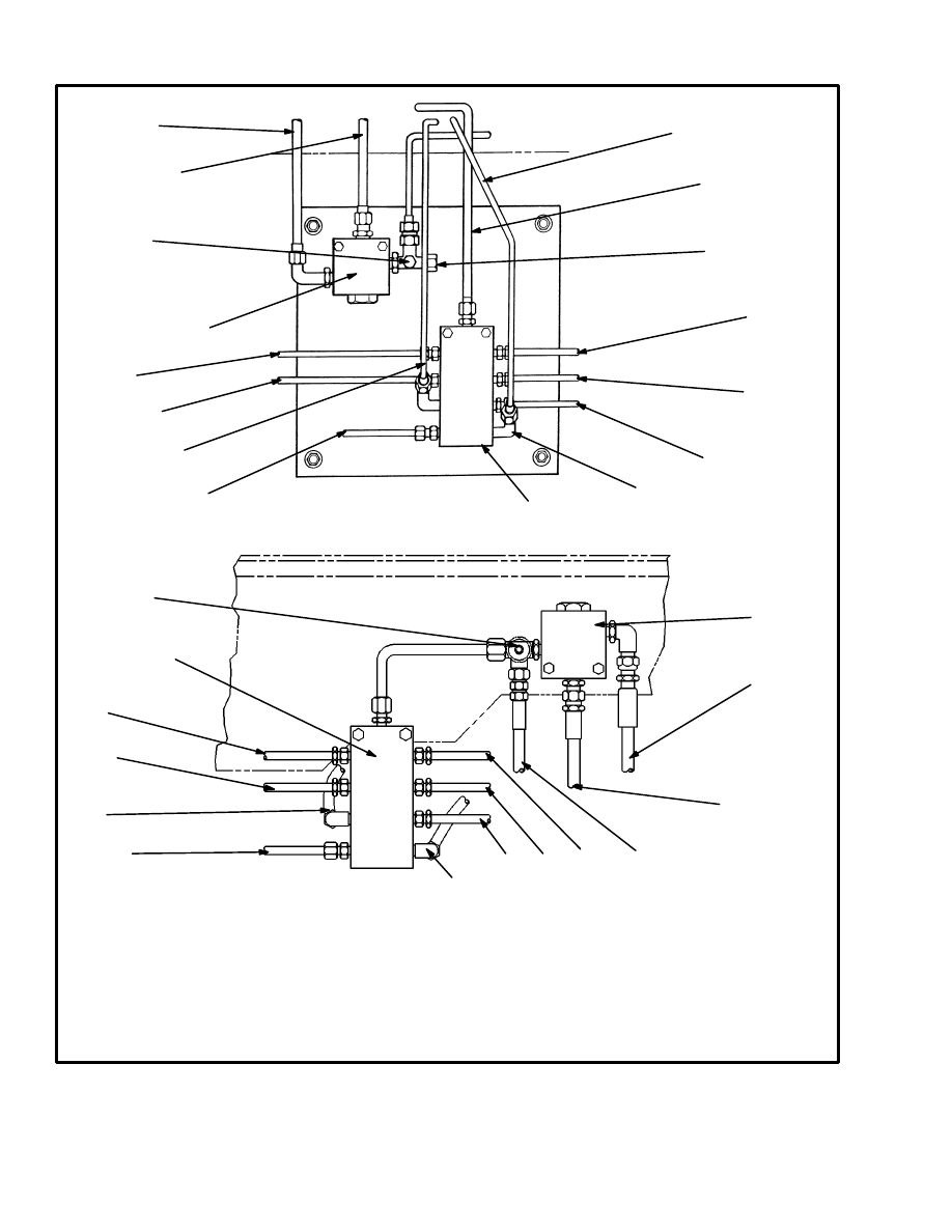
FIGURE 11. BRAKE LINE CONNECTIONS
1. SHUTTLE VALVE
2. TO INCHING/BRAKE PEDAL
3. TO SERVICE BRAKE PEDAL
4. TO RELAY VALVE
5. TO LEFT FRONT BRAKE CALIPER
6. TO LEFT REAR BRAKE CALIPER
7. TO PARKING BRAKE CALIPER
8. TO RELAY VALVE
9. TO AUXILIARY SERVICE BRAKE CALIPER
10. TO PILOT VALVE
11. TO RIGHT REAR BRAKE CALIPER
12. TO RIGHT FRONT BRAKE CALIPER
13. MANIFOLD
14. PRESSURE SWITCH
15. TO SEQUENCE VALVE
16. CHECK PORT
1
2
3
9
10
11
12
13
8
4
5
6
7
14
H36.00–48.00C (H800–1050C)
H20.00–32.00F (H440–700F/FS)
9
10
11
12
2
3
7
6
5
8
13
1
14
4
12741
15
16
15
Assembly and Installation
(See FIGURE 11. and FIGURE 12.)
1. Install new back–up rings and O–rings on the car-
tridge. Install the cartridge in the valve body. Tighten the
cartridge to 34 to 41 N.m (25 to 30 lbf ft).
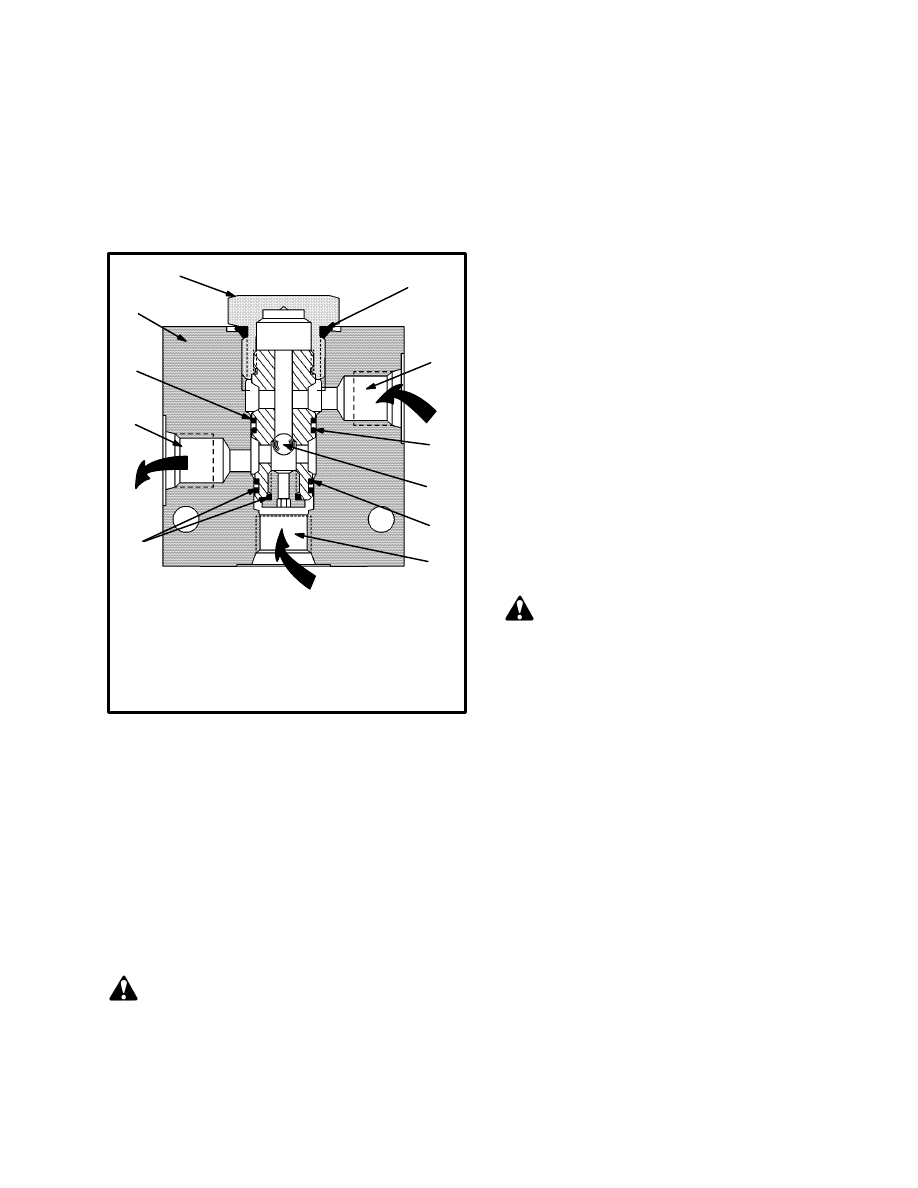
FIGURE 12. SHUTTLE VALVE
1. FROM INCHING/
BRAKE PEDAL
2. FROM SERVICE
BRAKE PEDAL
3. TO BRAKE CALIPERS
AND RELAY VALVE
2
3
1
5
4
7
6
4
8
5
4
4. O–RING
5. BACK–UP
RING
6. VALVE BODY
7. CARTRIDGE
8. BALL
2. Install the valve on the frame. Connect the lines to the
valve.
3. Operate the system and check the valve for leaks.
BRAKE PEDAL VALVES
Removal and Disassembly
(See FIGURE 13. and FIGURE 14.)
WARNING
Before disconnecting any hydraulic lines, release
pressure from the hydraulic circuit as follows:
a. Shut the engine off and completely lower the car-
riage.
b. Operate the lift/lower lever and the brake pedals
until the hydraulic pressure is released.
1. Put tags for identification on the lines. Disconnect the
lines from the brake pedal valve. Put caps on the open
lines. Remove the pedal assembly from the floor plate.
2. Remove a snap ring and the pin from the pedal.
3. Remove the capscrews that hold the valve body to the
base plate. Carefully pull the valve body from the base.
There are two compressed springs at the top of the valve.
4. Remove the piston and boot from the pedal. Remove
the springs.
5. Remove the shims, ball retainer and ball from the
valve body.
6. Remove the nut and washer from the end plug. Re-
move the end plug, spring and spool. Remove and dis-
card the O–rings and cup seal from the sleeve.
7. Remove the sleeve and spacer.
Cleaning and Inspection
WARNING
Cleaning solvents can be flammable and toxic, and
can cause skin irritation. When using cleaning sol-
vents, always follow the solvent manufacturer’s rec-
ommended safety precautions.
Clean the parts in solvent. Inspect the spool and bores
for scratches. If there are scratches or other damage, the
parts must be replaced. Lubricate the parts with clean
hydraulic oil for assembly.
Assembly (See FIGURE 13.)
1. Install new O–rings and seals on the parts. Make sure
the cup seal is installed so that the open side is toward the
bottom of the pedal.
2. Install the piston assemblies in the housing.
3. Install the springs, retainers and the inner housing. In-
stall the pedal assembly.
Installation
1. Install the brake pedal valve to the floor plate.
16
FIGURE 13. SERVICE AND INCHING/BRAKE PEDAL VALVE
1. PEDAL
2. PIN
3. CAPSCREW
4. NUT
5. RUBBER BOOT
6. PISTON
7. BASE PLATE
8. BUSHING
9. SPRING
10. SHIM(S)
11. BALL RETAINER
12. BALL
13. SPACER
14. O–RING
15. SPOOL
16. CUP SEAL
17. TO DRAIN CIRCUIT
18. TO SERVICE BRAKES
19. SLEEVE
20. INLET
21. SPRING
22. END PLUG
23. WASHER
24. NUT
1
2
2
3
4
5
6
7
3
8
9
10
11
12
13
14
14
14
16
15
17
18
14
20
21
19
24
22
23
2. Connect the lines to the valve.
3. Check the brake pedal valve for leaks.
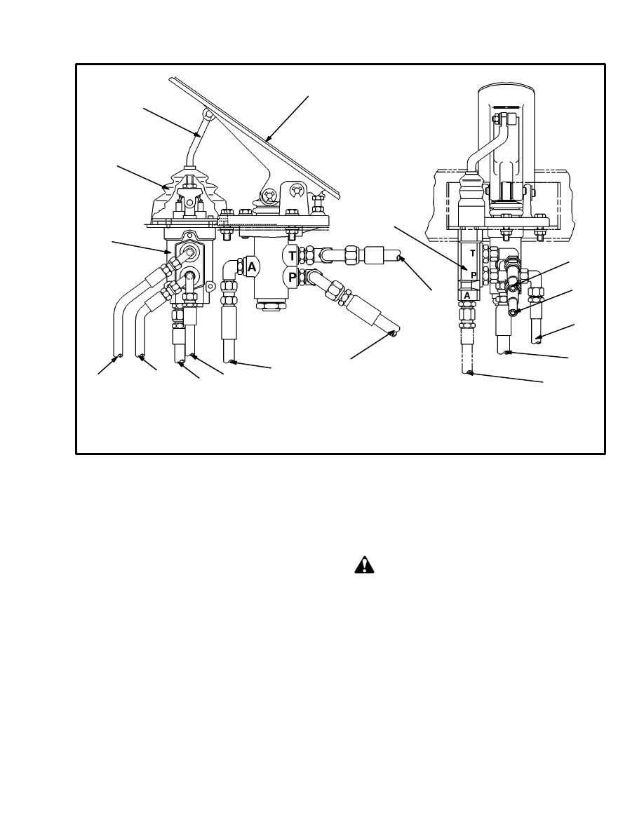
INCHING VALVE
Removal (See FIGURE 14.)
WARNING
Before disconnecting any hydraulic lines, release
pressure from the hydraulic circuit as follows:
a. Shut the engine off and completely lower the car-
riage.
b. Operate the lift/lower lever and the brake pedals
until the hydraulic pressure is released.
1. Disconnect the lever for the inching valve at the in-
ching/brake pedal. Remove the rubber boot from the
valve. Loosen the floor plates.
2. Make sure that the hydraulic lines have tags for identi-
fication. Disconnect the hydraulic lines from the valve.
Put caps on the open lines.
3. Remove the two screws that hold the valve to the floor
plate.
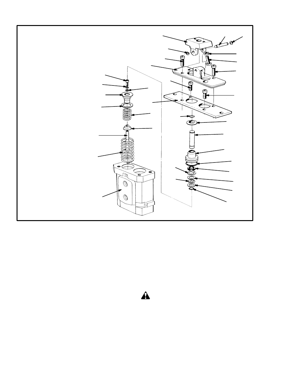
Disassembly (See FIGURE 15.)
NOTE: It is not necessary to remove the plug and parts
from the side of the valve that is not used. Some parts of
the valve are adjusted with shims. Make a note of the
number and location of the shims. Changing the shims
will affect the operation of the valve.
17
FIGURE 14. INCHING/BRAKE PEDAL VALVE ARRANGEMENT
1. INCHING/BRAKE PEDAL
2. INCHING VALVE
3. LEVER
4. RUBBER BOOT
3
4
5
6
11
10
5
8
1
7
8
9
6
9
7
5. TO DRAIN CIRCUIT
6. TO PARKING BRAKE VALVE
7. TO TRANSMISSION VALVE
8. FROM PRESSURE REDUCTION VALVE
9. TO SHUTTLE VALVE
10. FROM ACCUMULATOR
11. TO DRAIN CIRCUIT
2
2
1. Remove the capscrews and nuts that fasten the valve
to the cover. Remove the cover from the valve.
2. Remove the rubber boot from the plate (4). Remove
the pivot pin (7) for the control lever. Remove the con-
trol lever and boot.
3. Put identification marks on the valve body and the
plates at the top of the valve body. Carefully remove the
capscrews that hold the plates to the top of the valve
body. Remove the plates.
4. Remove a pin and guide assembly (25, 26) from the
valve body.
5. Carefully remove the spring assembly (12–18) and
the spool (11) from the same bore in the valve body. Re-
move the return spring (10).
Cleaning and Inspection
WARNING
Cleaning solvents can be flammable and toxic, and
can cause skin irritation. When using cleaning sol-
vents, always follow the solvent manufacturer’s rec-
ommended safety precautions.
Clean the parts in solvent. Inspect the spools and bores
for scratches. If there are scratches or other damage, the
valve must be replaced. Spools are not available as sepa-
rate parts. Lubricate the parts with clean hydraulic oil
for assembly.
Assembly (See FIGURE 15.)
1. Install the return springs (10) in the valve body.
18
FIGURE 15. INCHING VALVE
*
1.3 N.m (12 lbf ft)
11429
1. MOUNT, HAND LEVER
2. LOCK RING
3. SCREW
4. PRESSURE PLATE
5. SCREW
6. PLATE
7. PIVOT PIN
8. NUT
9. SCREW, ADJUSTMENT
10. RETURN SPRING
11. SPOOL
12. GUIDE
13. SPRING
14. SHIM
15. SPRING GUIDE
16. WASHER
17. SHIM
18. SCREW
19. O–RING
20. SHIM
21. LOCK RING
22. SNAP RING
23. SEAL
24. O–RING
25. GUIDE
26. PIN
27. RETAINER
28. LOCK WIRE
29. VALVE BODY
1
7
2
3
8
9
2
3
4
18*
15
19
20
21
22
25
26
27
28
6
5
5
12
13
14
20
11
10
29
23
24
17
16
2. Make sure that the same shims (14, 17) are used with
the spring assembly. Install the spring assembly and
spool in the bore. Make sure that the parts are installed in
the same bores from which they were removed.
3. Assemble the guide and pin assemblies (19–28). In-
stall the O–rings and guides in the valve body.
4. Install the plates (4 and 6) at the top of the valve.
Tighten the screws to 5 N.m (44 lbf in). Install the lever
and tighten the lock nut on the lever to 30 N.m (22 lbf ft).
Installation (See FIGURE 14.)
1. Install the valve on the floor plate. If necessary, adjust
the position of the lever so that it aligns with the pedal.
Install the rubber boot on the valve.
2. Connect the hydraulic lines to the valve as shown in
FIGURE 14.
3. Start the engine and check for leaks.
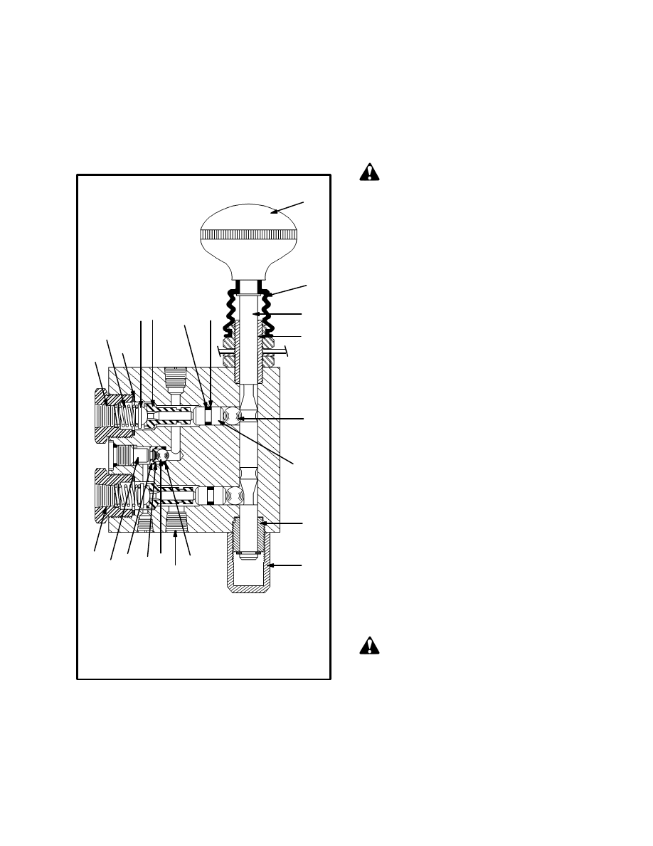
PARKING BRAKE VALVE
Removal (See FIGURE 16.)
WARNING
Before disconnecting any hydraulic lines, release
pressure from the hydraulic circuit as follows:
a. Shut the engine off and completely lower the car-
riage.
b. Operate the lift/lower lever and the brake pedals
until the hydraulic pressure is released.
19
1. Remove the knob and rubber boot from the rod. Re-
move the nut that holds the valve to the instrument pan-
el.
2. Put tags for identification on the lines. Disconnect the
lines from the parking brake valve. Put caps on the open
lines. Remove the valve.
FIGURE 16. PARKING BRAKE VALVE
11. BUSHING
12. END CAP
13. TO DRAIN CIRCUIT
14. BALL
15. SPRING
16. CAGE
1
2
3
4 5
7
8
20
19
10
11
9
6
11
12
13
7
14
15
16
17
18
1. INLET PORT
2. SPRING
3. GASKET
4. VALVE STEM
5. VALVE
6. PISTON
7. O–RING
8. BACK–UP RING
9. BALL
10. ROD
17. PLUG
18. TO PILOT VALVE
19. RUBBER BOOT
20. KNOB
Disassembly (See FIGURE 16.)
1. Remove the fittings from the inlet and outlet ports.
Remove the spring, valve stem, valve, piston and ball
from each port. Keep the parts from each port together.
2. Remove the plug, cage, spring, check ball and O–ring.
3. Unless replacement is necessary, do not remove the
rod and bushings. The end cap and lower bushing are
held in position with Loctite.
Cleaning and Inspection
WARNING
Cleaning solvents can be flammable and toxic, and
can cause skin irritation. When using cleaning sol-
vents, always follow the solvent manufacturer’s rec-
ommended safety precautions.
Clean the parts in solvent. Inspect the parts and bores for
scratches. If there are scratches or other damage, the
valve must be replaced. Lubricate the parts with clean
hydraulic oil for assembly.
Assembly (See FIGURE 16.)
1. Install new back–up rings and O–rings on the pistons.
Install the ball, piston, valve, valve stem, spring, gasket
and fitting in each port.
2. Install a new O–ring for the check ball. Install the
check ball, cage and spring. Install the plug.
3. Install the other plugs in the valve body.
Installation (See FIGURE 16.)
1. Install the parking brake valve on the instrument
panel. Install the nut to hold the valve in position. Con-
nect the lines as shown in FIGURE 1. Tighten the nut for
the valve body. Install the rubber boot and the knob.
2. Operate the system and check for leaks and correct
operation of the parking brake system.
PARKING BRAKE CALIPER
WARNING
Put blocks in front and back of the tires so that the lift
truck cannot move.
Removal
1. Put blocks in front and back of the tires so that the lift
truck cannot move.
2. Remove cotter pin (13) and tighten the nut (12) to re-
lease the parking brake.
20
WARNING
Before disconnecting any hydraulic lines, release
pressure from the hydraulic circuit as follows:
a. Shut the engine off and completely lower the car-
riage.
b. Operate the lift/lower lever and the brake pedals
until the hydraulic pressure is released.
3. Release pressure from the accumulator. Disconnect
the hydraulic line at the caliper. Put a cap on the open
line.
4. Remove the pins that hold the caliper to the bracket.
Remove the caliper and brake linings.
DANGER
Brake linings contain dangerous fibers. Breathing
the dust from these linings can be a cancer or lung
disease hazard. Do not create dust! Do not clean
brake parts with compressed air or by brushing. Fol-
low the cleaning procedure in this section.
Do not sand, grind, chisel, hammer or change linings
in any way that will create dust. Any changes to lin-
ings must be done in a restricted area with special
ventilation. Protective clothing and a respirator
must be used.
Disassembly (See FIGURE 18.)
1. Remove the nut from the stud (10). Carefully remove
the cover from the caliper housing. Remove the washers
and springs from the housing.
2. Pull the piston from the bore.
Cleaning
1. Do not release brake lining dust from the brake linings
into the air.
2. Use a solvent approved for cleaning of brake parts to
wet the brake lining dust. Follow the instructions and
cautions of the manufacturer for the use of the solvent. If
a solvent spray is used, do not disturb brake lining dust
with the spray.
3. When the brake lining dust is wet, clean the parts. Put
any cloth or towels in a plastic bag or an airtight con-
tainer while they are still wet. Put a “DANGEROUS FI-
BERS” warning label on the plastic bag or airtight con-
tainer.
4. Any cleaning cloths that will be washed must be
cleaned so that brake lining fibers are not released into
the air.
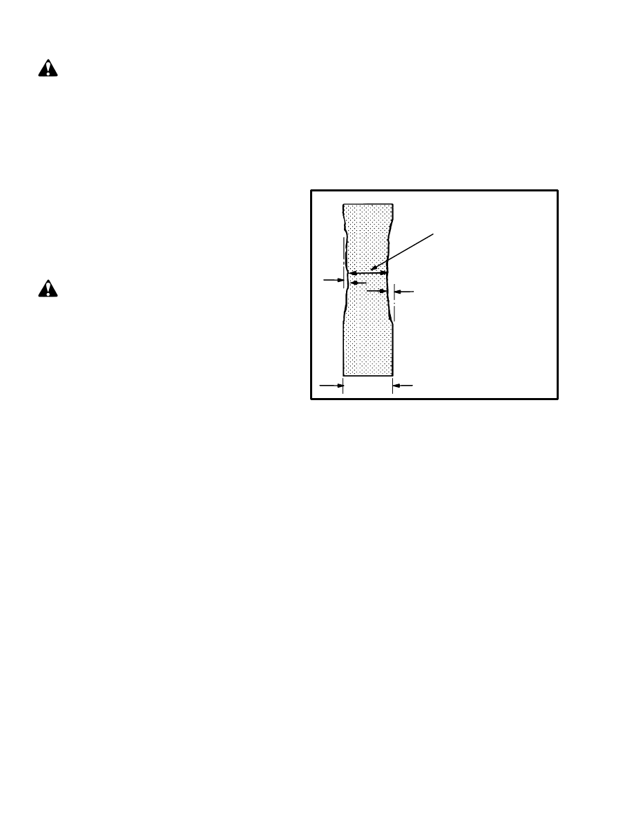
Inspection
Inspect the parts and bores for scratches. If there are
scratches or other damage, replace the damaged parts.
Inspect the rotor as shown in FIGURE 17.
FIGURE 17. INSPECT THE ROTOR FOR THE
PARKING BRAKE AND AUXILIARY
CALIPERS
12406
1. MAXIMUM ROTOR
WEAR 1.5 mm (0.06 in)
2. MINIMUM ROTOR
THICKNESS
17.0 mm (0.67 in)
3. ROTOR THICKNESS
20.07 mm (0.79 in)
3
2
1
1
Assembly (See FIGURE 18.)
1. Lubricate the piston with clean hydraulic oil. Install
the O–rings and back–up rings on the piston. Install the
piston in the housing.
2. Install the washers and spring assembly in the hous-
ing. Install the spring cover in the housing.
3. Install the washer and nut on the stud. Tighten the nut
to retract the piston.
Installation and Adjustment
(See FIGURE 18.)
1. Install the caliper on the bracket. Install the alignment
pins, O–rings and cotter pins.
2. Connect the hydraulic line to the caliper. Loosen the
nut (12).
3. Adjust the brake linings as follows:
a. Put blocks in front and back of the tires so that the lift
truck cannot move.
21
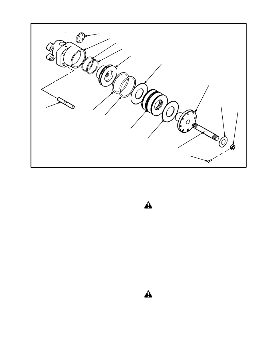
FIGURE 18. PARKING BRAKE CALIPER
12715
1. BRAKE LINING (2)
2. CALIPER HOUSING
3. ALIGNMENT PIN
4. BACK–UP RING
5. O–RING
6. PISTON
1
2
3
4
5
6
5
4
7
8
7
9
10
11
12
13
7. WASHER
8. SPRING
9. SPRING COVER
10. STUD
11. WASHER
12. NUT
13. COTTER PIN
b. Start the engine and release the parking brake (apply
hydraulic pressure). Check that the caliper moves
freely on the alignment pins.
c. Slide the caliper so that one of the brake linings is
against the brake rotor. Measure the clearance be-
tween the brake lining and the rotor. If the clearance is
more than 3.4 mm (0.13 in), continue with these ad-
justment procedures.
d. Turn the nut (12) until it just touches the spring cov-
er (9). Apply the parking brake (release hydraulic
pressure).
e. Turn the spring cover (9) clockwise (tighten) until
both linings touch the rotor. Turn the spring cover
counterclockwise 1 1/2 turns, then measure the clear-
ance between the lining and the rotor. Turn the spring
cover as necessary to obtain the correct clearance of
2.2 mm (0.090 in).
f. Release the parking brake. Loosen the nut (12) and
install the cotter pin (13).
SERVICE BRAKE CALIPERS
Removal (See FIGURE 19.)
WARNING
Completely remove the air pressure from the tires
before removing the wheels from the lift truck. Air
pressure in the tires can cause the tire and rim parts
to explode causing serious injury or death.
Always wear safety glasses.
1. Remove the air from the tire. Remove the valve core
to make sure that all of the air is out of the inner tube.
Push a wire through the valve stem to make sure that the
valve stem does not have a restriction.
2. Remove the wheel nuts and clamps, then remove the
wheels from the lift truck. Lift truck wheels are heavy.
DANGER
Brake linings contain dangerous fibers. Breathing
the dust from these linings can be a cancer or lung
disease hazard. Do not create dust! Do not clean
22
brake parts with compressed air or by brushing. Fol-
low the cleaning procedure in this section.
Do not sand, grind, chisel, hammer or change linings
in any way that will create dust. Any changes to lin-
ings must be done in a restricted area with special
ventilation. Protective clothing and a respirator
must be used.
3. Remove the end plates from the calipers. Remove the
brake linings from the calipers.
FIGURE 19. BRAKE CALIPER
12417
1. BRAKE CALIPER
2. BRAKE ROTOR
1
2
3
1
4
3. BRAKE LINING
4. END PLATE
4. Disconnect the brake lines at the calipers. Remove the
capscrews that hold the caliper to the axle housing.
Make a note of the location of any shims that are used at
the caliper mount.
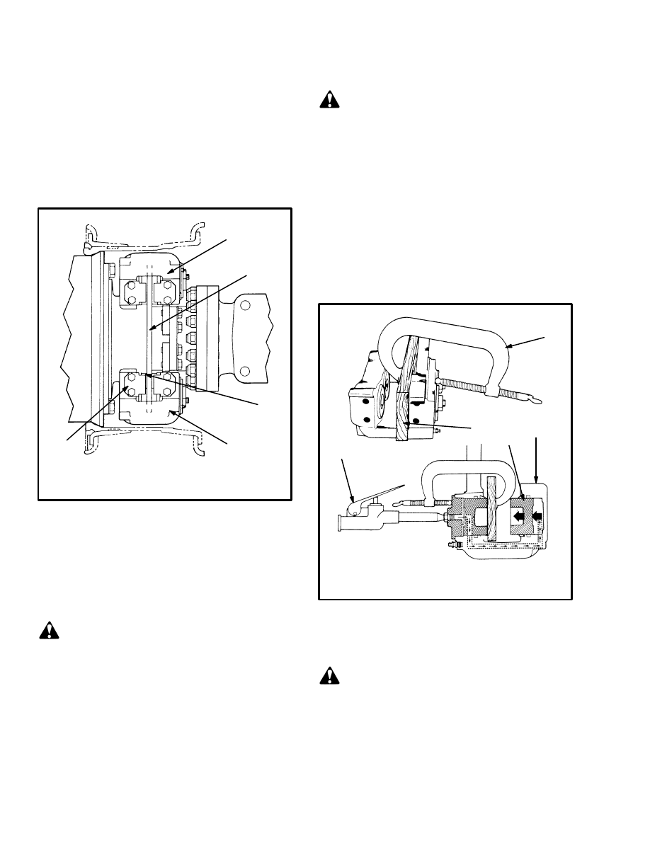
Disassembly (See FIGURE 21.)
CAUTION
Put marks on the pistons so that they can be installed
in their original bores during installation.
1. Remove the inlet fitting and the O–ring from the cyl-
inder head. Drain the hydraulic fluid from the caliper.
2. Remove the pistons from the side of the housing op-
posite the cylinder heads as follows:
a. Use a C–clamp to hold a 13 mm (0.5 in) block of
wood against the pistons with the cylinder heads.
Make sure the C–clamp is not in front of the opposite
piston bore.
WARNING
Compressed air can move particles so that they
cause injury to the user or to other personnel. Make
sure that the compressed air path is away from all
personnel. Wear eye protection.
b. See FIGURE 20. Apply compressed air to the inlet
fitting to push the pistons from the housing. If one pis-
ton comes out before the other pistons, put a piece of
wood in front of the piston that comes out first.
c. Remove the wood block and C–clamp from the cali-
per. Remove the pistons from the side of the housing
opposite the cylinder heads.
FIGURE 20. REMOVE THE PISTON
12406
1. C–CLAMP
2. WOOD BLOCK
3. AIR GUN
4. CALIPER
5. PISTON
1
2
3
4
5
3. Remove the special fittings from the housing. Re-
move the cylinder heads from the housing.
WARNING
Do not put your hand in front of the piston when re-
moving the piston. The piston can move with force
and cause personal injury.
4. See FIGURE 22. Push the pistons from the housing.
Do not remove the pistons from the side of the housing
with the cylinder heads.
23
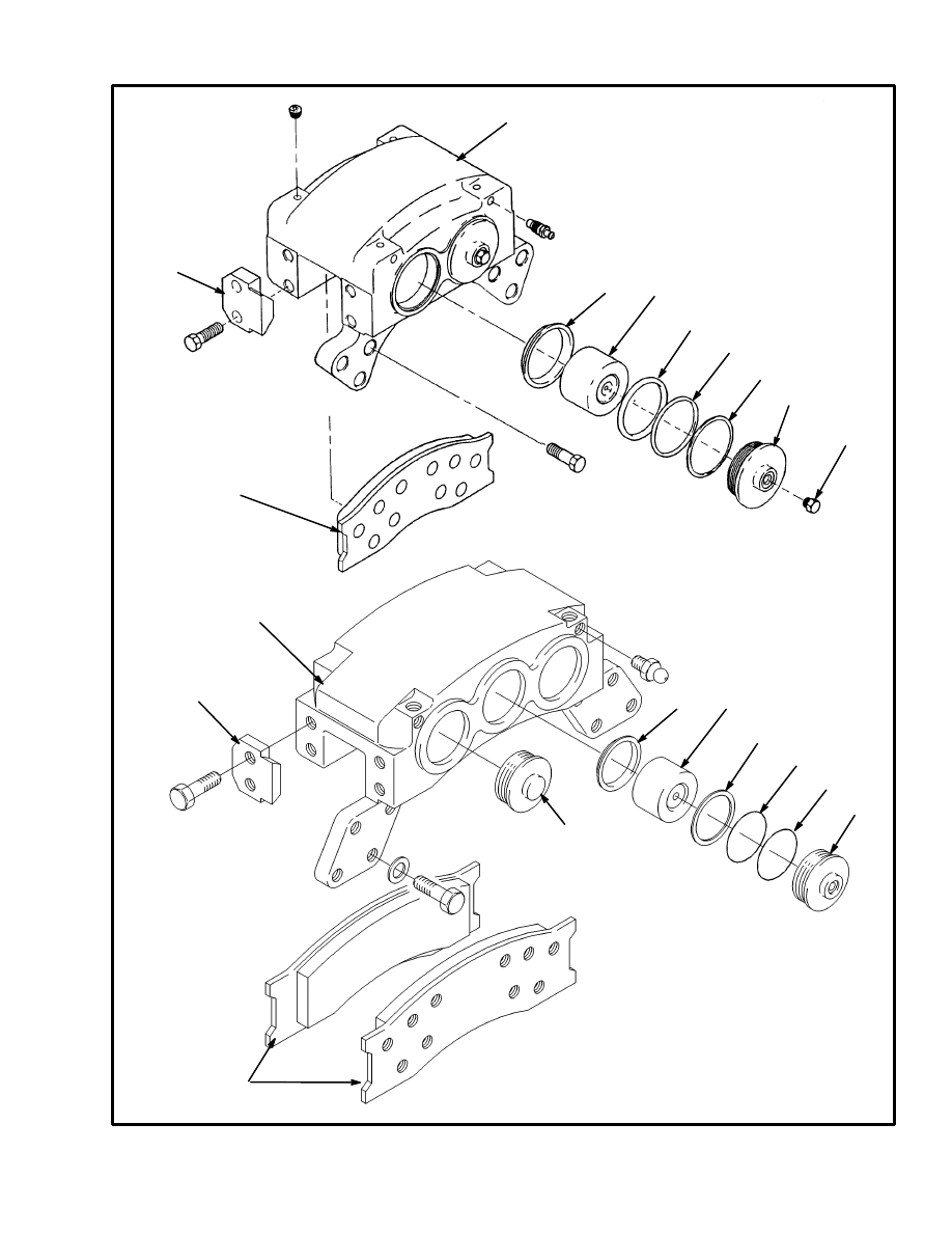
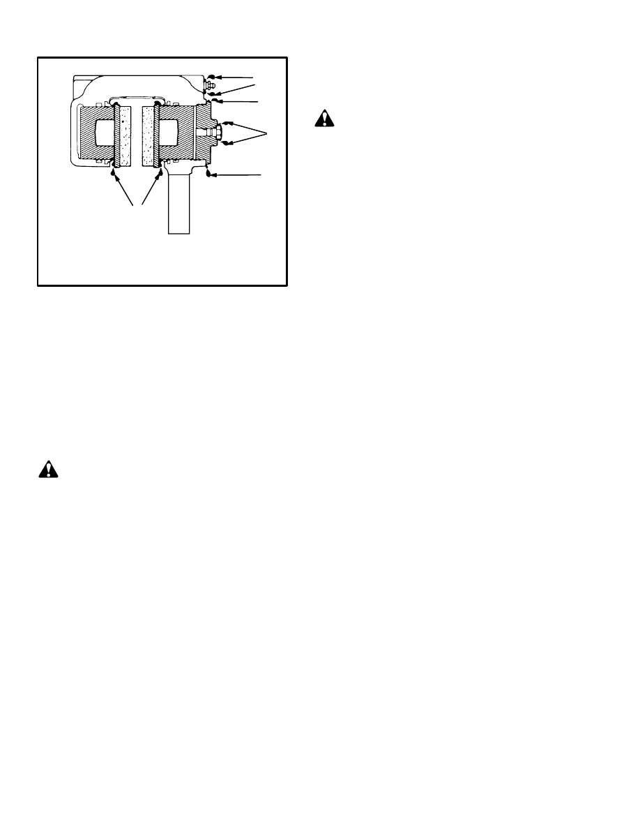
FIGURE 21. BRAKE CALIPER
12404
1. CALIPER HOUSING
2. END PLATE
3. BRAKE LINING
4. DUST COVER
5. PISTON
6. BACK–UP RING
7. O–RING (PISTON)
8. O–RING (CYLINDER HEAD)
9. CYLINDER HEAD
10. PLUG
1
1
3
2
3
5
5
4
4
6
7
6
7
8
9
8
9
10
9
2
TWO PISTON CALIPER
H20.00–32.00F (H440–700F/FS)
THREE PISTON CALIPER
H36.00–48.00C (H800–1050C)
*H28.00–32.00F (H620–700F/FS)
*Early Units Only
24
FIGURE 22. REMOVE THE PISTON
12406
1. WOOD BLOCK
2. PISTON
1
2
5. Remove the O–rings and back–up rings from the
housing. Remove the dust covers from the housing.
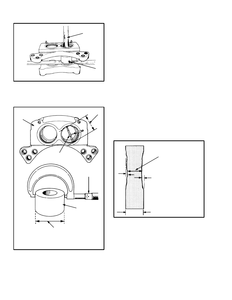
FIGURE 23. INSPECT THE CALIPER
4. CALIPER HOUSING
5. 76.27 mm (3.003 in)
6. 76.07 mm (2.995 in)
12406
1. INSIDE GAUGE
2. MICROMETER
3. PISTON
4
5
1
2
6
3
Cleaning
1. Do not release brake lining dust from the brake linings
into the air.
2. Use a solvent approved for cleaning of brake parts to
wet the brake lining dust. Follow the instructions and
cautions of the manufacturer for the use of the solvent. If
a solvent spray is used, do not disturb brake lining dust
with the spray.
3. When the brake lining dust is wet, clean the parts. Put
any cloth or towels in a plastic bag or an airtight con-
tainer while they are still wet. Put a “DANGEROUS FI-
BERS” warning label on the plastic bag or airtight con-
tainer.
4. Any cleaning cloths that will be washed must be
cleaned so that brake lining fibers are not released into
the air.
Inspection
1. Inspect the brake linings as shown in FIGURE 25. In-
spect the brake rotor as shown in FIGURE 24. See THE
DRIVE AXLE, 1400 SRM 47 if the rotors need re-
placement.
FIGURE 24. INSPECT THE ROTOR
12406
1. MAXIMUM ROTOR
WEAR 1.5 mm (0.06
in)
2. MINIMUM ROTOR
THICKNESS
12.7 mm (0.50 in)
3. ROTOR THICKNESS
15.88 mm (0.625 in)
3
2
1
1
2. Inspect the pistons and the bores for wear, damage or
rust. Remove any small scratches or rust with emery pa-
per.
3. Inspect the grooves for the O–rings and back–up rings
for damage.
4. Measure the outside diameter of the piston. (See
FIGURE 23.) Replace the piston if the outside diameter
is less than 76.07 mm (2.995 in).
25
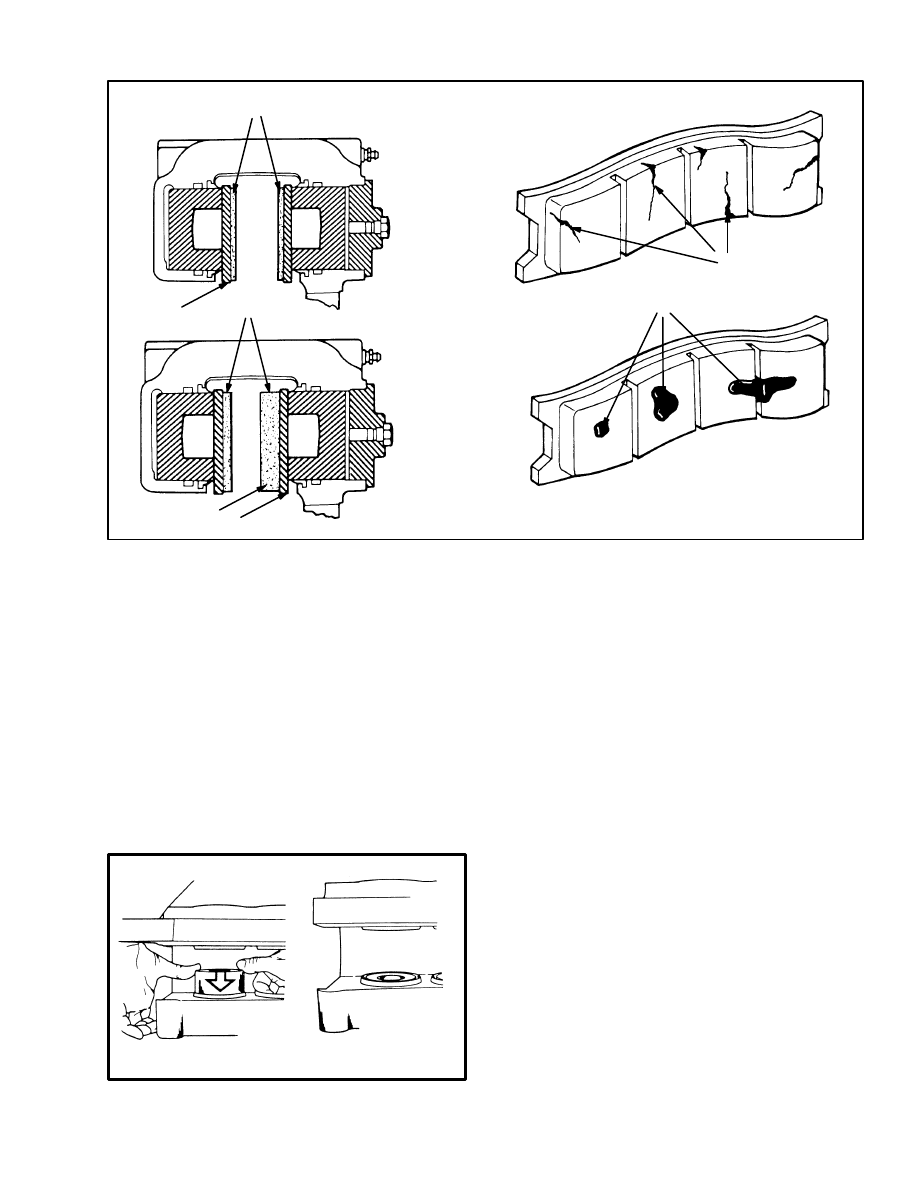
FIGURE 25. INSPECT BRAKE PARTS
12406
1. MINIMUM LINING THICKNESS
3.0 mm (0.13 in) FROM BACK PLATE
4. UNEVEN LINING WEAR
5. CRACKED LININGS
6. OIL OR GREASE ON LININGS
2. LINING
3. BACK PLATE
2
3
4
3
1
5
6
5. Measure the inside diameter of the bore for the piston.
(See FIGURE 23.) Replace the housing if the inside di-
ameter is more than 76.27 mm (3.003 in).
Assembly (See FIGURE 21.)
NOTE: Lubricate all of the internal parts with clean hy-
draulic oil.
1. Install a new O–ring and back–up ring in the middle
groove in the bore. The back–up ring fits closest to the
brake lining.
FIGURE 26. INSTALL THE PISTONS
STEP 1.
STEP 2.
12405
2. Install new dust covers in the top groove of the bore.
Install the piston in the bore. See FIGURE 26. Push the
piston in from the brake lining side of the caliper. Push
each piston into the bore until the top of the piston is
even with the top of the dust cover.
3. Install new O–rings on the cylinder heads. Install the
cylinder heads, tightening them to 100 N.m (75 lbf ft).
4. Install the inlet fittings and special screws in the cali-
per.
Installation (See FIGURE 19.)
1. Install the caliper on the mount at the axle housing.
2. Make sure the pistons are pushed completely into the
bores. Install the brake linings in the caliper. Install the
end plates on the caliper. Use a thread locking com-
pound and install the capscrews for the end plates.
Tighten the capscrews to 230 N.m (170 lbf ft). Check to
make sure that the brake linings move freely in the cali-
per.
3. Remove the air from the brake system as described in
CHECKS AND ADJUSTMENTS. Check the calipers
for leaks. See FIGURE 27.
26
FIGURE 27. CHECK FOR LEAKS
12405
1. LEAKS AT PISTON
2. LEAKS AT SCREWS
3. LEAKS AT INLET
FITTING
4. LEAKS AT
CYLINDER
HEAD
2
1
3
4
4
AUXILIARY BRAKE CALIPER
Removal
1. Disconnect the hydraulic line at the caliper. Put a cap
on the open line.
2. Remove the retainers for the brake linings.
2. Remove the capscrews that hold the caliper to the
bracket. Remove the caliper and brake linings.
DANGER
Brake linings contain fibers and the dust from these
linings can be a cancer or lung disease hazard. Do not
create dust! Do not clean brake parts with com-
pressed air or by brushing. Use vacuum equipment
that is designed to be used to remove asbestos fibers
to remove the lining dust. When the brake drums are
removed, do not create dust.
Do not sand, grind, chisel, hammer or change linings
in any way that will create dust. Any changes to lin-
ings must be done in a restricted area with special
ventilation. Protective clothing and a respirator
must be used.
Disassembly (See FIGURE 28.)
1. Remove the tube that connects the caliper halves, then
separate the halves of the brake caliper.
2. Put identification marks on the pistons for correct as-
sembly. Remove the boots from the pistons. Pull the pis-
tons from the caliper.
3. Remove the lock ring to remove the guide assembly
from the piston. When disassembling the guide assem-
blies, be careful of the springs.
CAUTION
Put marks on the pistons so that they can be installed
in their original bores during installation.
Cleaning
1. Do not release brake lining dust from the brake linings
into the air.
2. Use a solvent approved for cleaning of brake parts to
wet the brake lining dust. Follow the instructions and
cautions of the manufacturer for the use of the solvent. If
a solvent spray is used, do not disturb brake lining dust
with the spray.
3. When the brake lining dust is wet, clean the parts. Put
any cloth or towels in a plastic bag or an airtight con-
tainer while they are still wet. Put a “DANGEROUS FI-
BERS” warning label on the plastic bag or airtight con-
tainer.
4. Any cleaning cloths that will be washed must be
cleaned so that brake lining fibers are not released into
the air.
Inspection
Inspect the the pistons and the bores for wear, damage or
rust. Inspect the rotor as shown in FIGURE 17. Remove
any small scratches or rust with emery paper. Replace
damaged parts.
Assembly (See FIGURE 28.)
1. Install the guide pins with O–rings in the caliper.
2. Install the guide assemblies in the pistons. Install the
threaded ring and lock ring to hold the parts in the pis-
tons.
3. Install the O–rings for the pistons. Install the pistons
and boots.
Installation
1. Install the caliper on the bracket. Install the linings
and retainers.
27
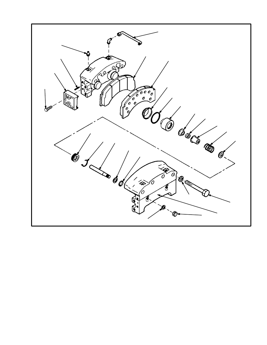
FIGURE 28. AUXILIARY BRAKE CALIPER
12714
1. NUT
2. LOCKWASHER
3. CALIPER HOUSING
4. WASHER
5. CAPSCREW
6. O–RING
7. GUIDE PIN
8. LOCK RING
9. THREADED RING
10. SPRING RETAINER
11. SPRING
12. OUTER SPRING GUIDE
13. GUIDE PIN ADJUSTER
14. INNER SPRING GUIDE
15. PISTON
16. BOOT
17. LINING
18. TUBE
19. FITTING
20. ROLL PIN
21. RETAINER
1
2
3
4
5
6
4
7
8
9
10
11
12
13
14
15
6
16
17
18
17
19
21
5
20
2. Install the tube between the caliper halves. Connect
the brake line to the caliper.
3. Remove the air from the brake system as described in
CHECKS AND ADJUSTMENTS.
CHECKS AND ADJUSTMENTS
REMOVE AIR FROM THE
BRAKE SYSTEM
Air must be removed from the brake system. Connect
one end of a hose to the special fitting on the brake cali-
per or other component. Put the other end of the hose in a
container filled with clean hydraulic fluid. Start the en-
gine and push on the brake pedal. Loosen the special fit-
ting on the brake caliper or other component.This action
pushes air out of the brake system.
Repeat the procedure until air bubbles are not seen in the
container. Repeat the procedure for the other special fit-
tings. It is necessary to remove approximately one litre
(one quart) of oil from the system to make sure all of the
air is removed.
28
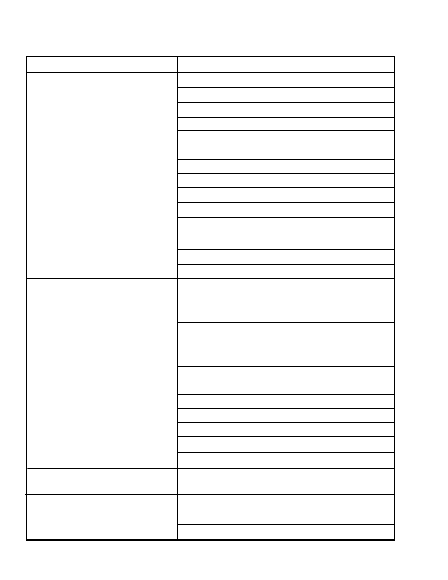
TROUBLESHOOTING
PROBLEM
CAUSE
The brakes do not stop the lift truck.
Oil, water or hydraulic oil is on the linings.
The linings are worn or damaged.
There is not enough hydraulic pressure in the system.
The brake lines have a restriction.
The accumulator charge valve or accumulator is damaged.
The pressure reduction valve is not adjusted correctly.
The brake pedal valve(s) is damaged.
The brakes apply slowly.
The hydraulic line(s) have a leak or restriction.
The brake pedal valve(s) is damaged.
The service brakes do not operate equally.
Oil or water is on the linings.
The linings are worn or damaged.
The brake line(s) have a restriction.
The brake rotor(s) is damaged or not smooth.
The brake(s) does not release.
The brake linings are damaged.
A brake line has a restriction.
The brake rotor is damaged.
The brake pedal valve is damaged.
The parking brake is applied.
The relay valve does not operate correctly.
The brake caliper(s) has a leak.
There is not enough hydraulic pressure in the system.
Brake pedal(s) goes to the floor.
There is air in the hydraulic system.
There is a leak(s) in a hydraulic line.
One of the brake pedal valves does not
operate the brakes.
The shuttle valve does not operate.
The brakes make noise.
Oil or water is on the linings.
The linings are worn.
The brake rotor(s) is damaged.
The shuttle valve does not operate correctly.
The sequence valve does not operate correctly.
The sequence valve does not operate correctly.
A seal(s) in the brake caliper(s) is damaged.
29
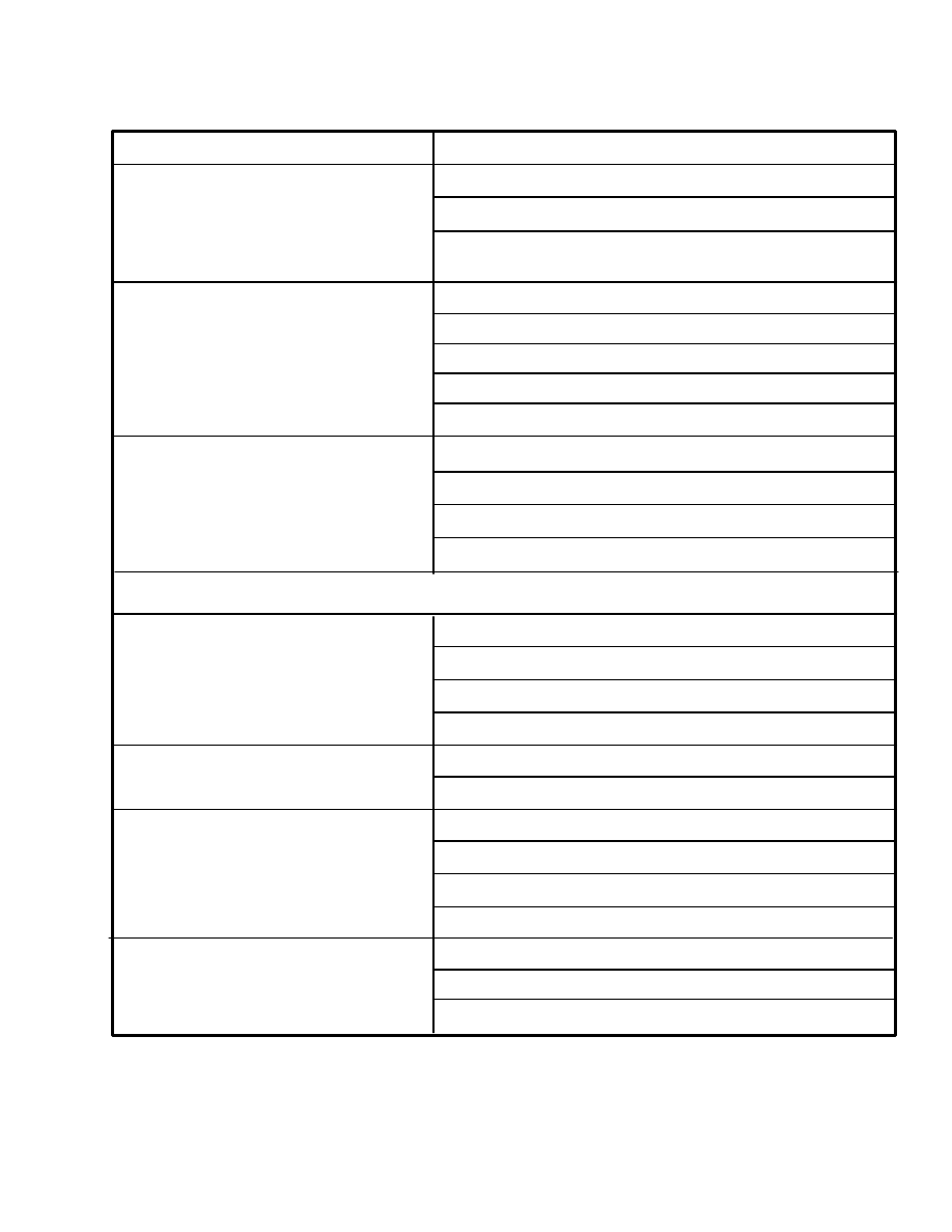
TROUBLESHOOTING
PROBLEM
CAUSE
The parking brake does not release.
The hydraulic pressure is too low.
The parking brake valve is a damaged.
The pilot valve does not operate correctly.
There is a leak(s) in the hydraulic lines.
The parking brake caliper is damaged.
The parking brake will not apply.
The spring in the brake caliper is damaged.
The brake linings are worn or damaged.
The brake rotor is worn or damaged.
Service brakes do not operate when
the
engine is not running.
There is no charge in the accumulator.
The accumulator charge valve does not operate correctly.
Hydraulic lines for the accumulator circuit leak or
have
restrictions.
The brake caliper is not adjusted correctly.
ACCUMULATOR CHARGE VALVE (See FIGURE 7.)
Accumulator fails to start charging.
Broken springs (5, 10).
O–ring (2) on plug for charging spool valve (9) leaks.
Charging spool valve (9) does not move.
Filter (13) is dirty.
Accumulator starts to charge but does
not
reach the high limit.
O–ring (2) for the sleeve (19) leaks.
O–ring (2) on charging spool valve (9) is damaged.
Accumulator charging cycles repeats when
system is not being used.
Check valve (15) leaks.
Lower limit ball (21) leaks.
Sleeve (13) is worn or damaged.
O–rings (2) for sleeve (13) or check valve seat (14) leak.
Accumulator charging time is too long.
Filter (13) is dirty.
Check valve (15) leaks.
Sleeve (13) is worn or damaged.

30
NEW Section GDN 8/91
PART NO. 897433 1800 SRM 472
1800 SRM 472
8/91 Litho in U.S.A.

31
APRIL 18
SAT
2:00 pm
. .
. . .
APRIL 20
MON
5:30 pm
. .
. .
APRIL 25
SAT
2:00 pm
. .
. . .
APRIL 29
WED
7:45 pm
. .
. .
MAY 2
SAT
9:00 am
. . . . .
. . .
MAY 4
MON
5:30 pm
. . . . .
. .
MAY 9
SAT
11:30 am
. . . . .
. . .
MAY 15
FRI
5:30 pm
. . . .
. . .
MAY 16
SAT
4:30 pm
. . . .
. . .
MAY 20
WED
5:30 pm
. . . .
. .
MAY 27
WED
5:30 pm
. . . .
. .
MAY 30
SAT
11:30 am
. . . .
. . .
JUNE 1
MON
5:30 pm
. . . .
. .
JUNE 4
THUR
5:30 pm
. . . .
.
JUNE 6
SAT
9:00 am
. . . .
. . .
JUNE 11
THUR
5:30 pm
. . .
.
JUNE 13
SAT
11:30 am
. . .
. . .
JUNE 17
WED
5:30 pm
. . .
. .
JUNE 20
SAT
4:30 pm
. . .
. . .
TYREL’S BASEBALL SCHEDULE
All games at EAST Gresham
(900 S.E. 5th) except April 29th
which is at JC field.
Document Outline
Wyszukiwarka
Podobne podstrony:
897653 1800SRM0566 (04 2005) UK EN
897653 1800SRM0566 (04 2005) UK EN
897457 8000SRM0488 (03 1992) UK EN
1510466 1800SRM0985 (05 2005) UK EN
897393 1800SRM0452 (02 2004) UK EN
1565789 1800SRM1117 (08 2005) UK EN
897670 1400SRM0575 (04 2005) UK EN
1565582 1600SRM1114 (04 2005) UK EN
1554629 1800SRM1076 (03 2004) UK EN
1494141 1800SRM0937 (12 2003) UK EN
1475871 1800SRM0785 (11 2003) UK EN
897658 1800SRM0570 (10 1999) UK EN
1482635 8000SRM0804 (04 2000) UK EN
1529749 1800SRM1036 (08 2005) UK EN
1531815 1800SRM1040 (03 2005) UK EN
897987 1800SRM0659 (09 2003) UK EN
więcej podobnych podstron