Automatic filters for mineral oil
Technical information for oil filtration

Inside view
3
Summary
4
Background
5
Filtration theory
8
The Alfa Laval filter
Design, automatic filter with diversion chamber
Features of the Alfa Laval automatic mineral oil filter
Operating principle, automatic filter with diversion
12
New filter range
Design, automatic filter with integrated centrifuge
Features of the Alfa Laval “Eliminator” automatic mineral oil filter
Operating principle, automatic filter with integrated centrifuge
16
Lubricating oil filtration
General
Designation and operation conditions for Alfa Laval lubricating oil filters
Alfa Laval lubricating oil filters for crosshead engines
Pre-lubrication
Dimensioning criteria for Alfa Laval lubricating oil filters
19
Fuel oil filtration
General
Designation and operation conditions for Alfa Laval fuel oil filters
Dimensioning criteria for Alfa Laval fuel oil filters
This technical information deals with filtration technology in general
and the Alfa Laval automatic filters in particular.
Alfa Laval Automatic Filters
2 Alfa Laval Marine & Diesel Equipment
Alfa Laval Marine & Diesel Equipment 3
Alfa Laval Automatic Filters
Summary
Automatic filters from Alfa Laval offer continuous engine protection. The filters
effectively use clean oil as the flushing medium to prevent any particles present
in lubricating oil or fuel oil from causing injector and engine damage.
Alfa Laval offers a range of automatic filters that provide full-
flow filtering of fuel and lubricating oils for trunk piston and
crosshead engines. Used in conjunction with a centrifugal
separator as part of a complete lubricating oil system or fuel
oil treatment system, these filters effectively separate impuri-
ties, according to size. Configuration is flexible, depending on
the application.
Continuous backflushing helps prevent adhesion of retained
solids to filter surfaces. This ensures long service intervals
and drastically reduces the costs for manual cleaning, filter
replacement and filter disposal. The robust disc-type filter
elements operate at a low and constant pressure drop, pro-
viding high filtering efficiency and reducing the risk of cracking.
These four different filter types are available:
• automatic filter for lubricating oil,
• automatic filter for lubricating oil with diversion chamber,
• automatic filter for lubricating oil with integrated centrifuge,
and,
• automatic filter for fuel oil.
The Alfa Laval filters have been installed on virtually all types
and brands of diesel engines.
The purpose of this document is to provide technical information
about Alfa Laval automatic filters. This includes information
about the filtration process, filter design and dimensioning,
working principles and operating conditions.
Benefits
• Easy to install and operate. These compact, lightweight
automatic filters require very little floor space. Hydraulically
driven by the pressure of the backflushing oil, the filters do
not require external power supply, compressed air or
electricity for operation.
• Flexible design. These filters are easily installed in varying
pipework configurations. Alternatives to the standard con-
figuration of these automatic filters are available to meet the
specific requirements of the engine manufacturer.
• High filtration efficiency. Robust disc-type filter elements
efficiently separate impurities according to size from the oil.
These elements operate at a low and constant pressure
drop, thus reducing the risk of cracking.
• Reduced maintenance costs. Continuous backflushing
helps prevent adhesion of retained solids to filter surfaces.
This ensures longer service intervals – up to 12,000 hours –
and drastically reduces the costs of manual cleaning, filter
replacement and filter disposal.
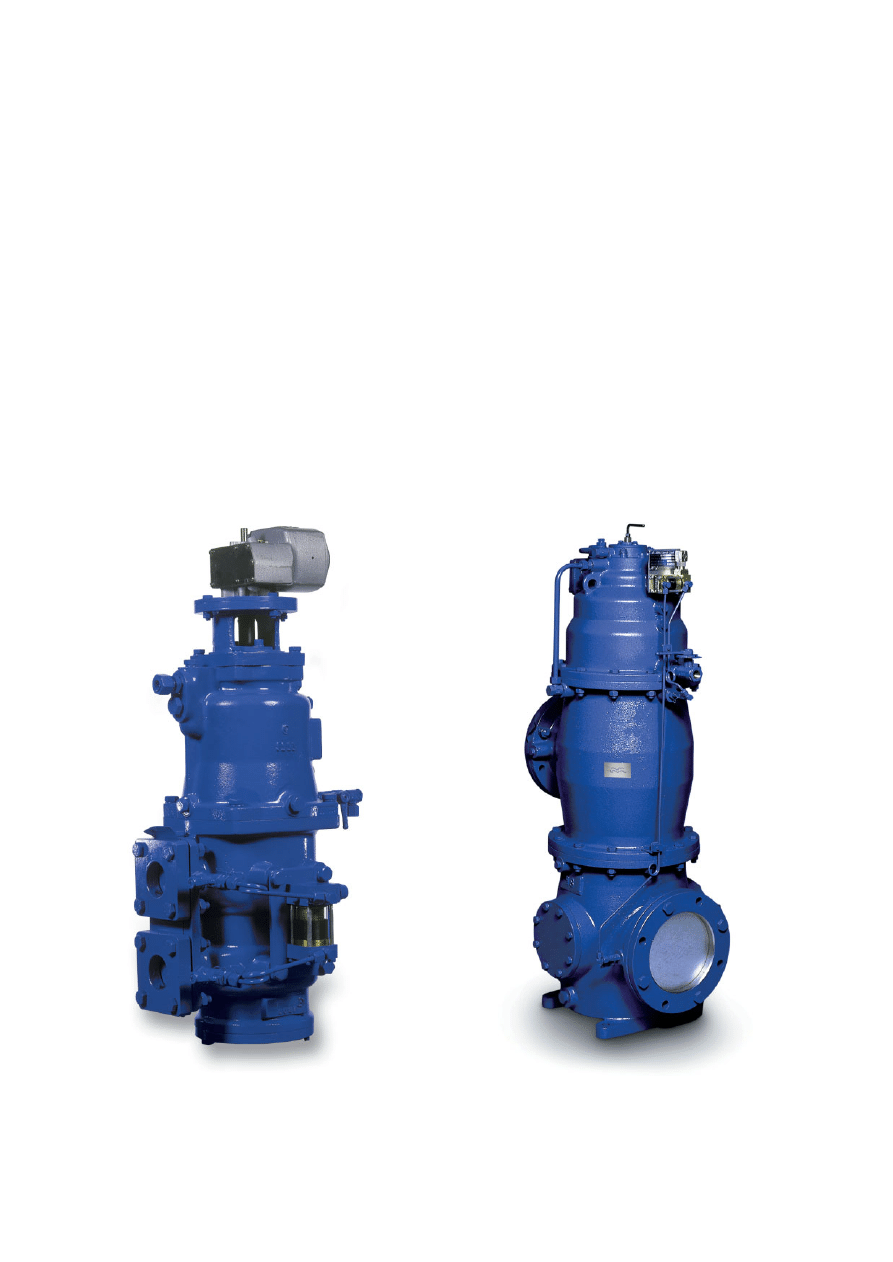
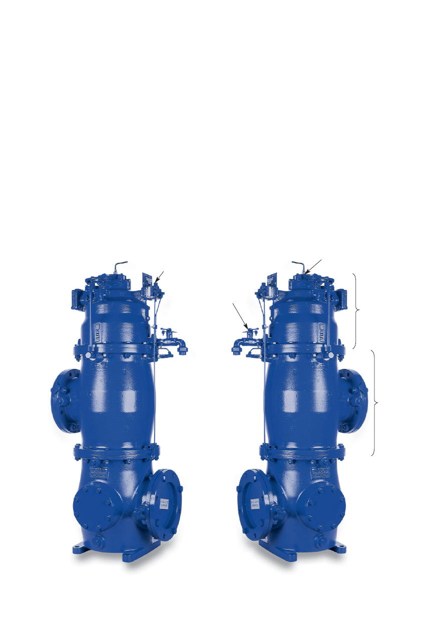
Lubricating oil filter
Lubricating oil filter
with diversion chamber
Lubricating oil filter
with integrated centrifuge
Fuel oil filter
Alfa Laval Automatic Filters
4 Alfa Laval Marine & Diesel Equipment
Background
The filter, in a mineral oil treatment system for diesel engines, is installed primarily
for preventing particles in the oil from entering the engine. Hence, the filter should
be placed as close to the engine as possible, whether it is operating as a fuel oil
or lubricating oil filter.
The centrifugal separator, on the other hand, cleans the oil
and removes the water. For these reasons, both the
separator and the filter are required in a modern mineral oil
cleaning system.
The main difference between a filter and a centrifugal sepa-
rator is that a filter separates the impurities according to size,
while a separator works with the density difference between
the impurities and the oil.
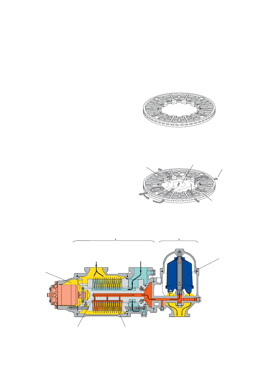
Automatic full-flow filter for lubricating oil.
Automatic full-flow filter for fuel oil.
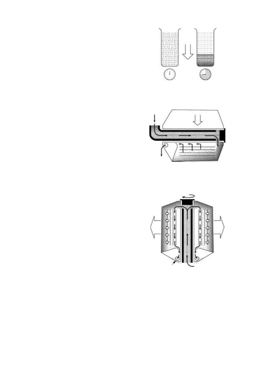
Filtration theory
Filtration can be defined as the process of collecting solid particles from a fluid by
passing the fluid through a filter medium (which could be a filter screen or a paper
element) where the particles are retained.
Two basic methods of filtration are used:
1. surface filtration, used in strainers and cake filters, and,
2. deep-bed filtration, used in depth filters.
The principles of particle collection in surface filtration and
deep-bed filtration are entirely different.
In surface filtration the particles are collected on the surface
of the filter medium, whereby a filter cake of retained
particles is created. This cake can be removed by
backflushing the filter.
In deep-bed filtration the particles pass through a filter and
are collected inside the filter. Since different capture
mechanisms are used in surface filtration and deep-bed
filtration, the value of comparing filter finenesses of the two
types is questionable.
Figure 2 shows the different mechanisms operating in
surface filtration and deep-bed filtration, respectively.
As the solid particles accumulate in a depth filter, the
pressure drop increases during filtration. When the pressure
drop reaches a certain level, the filter elements must be
replaced.
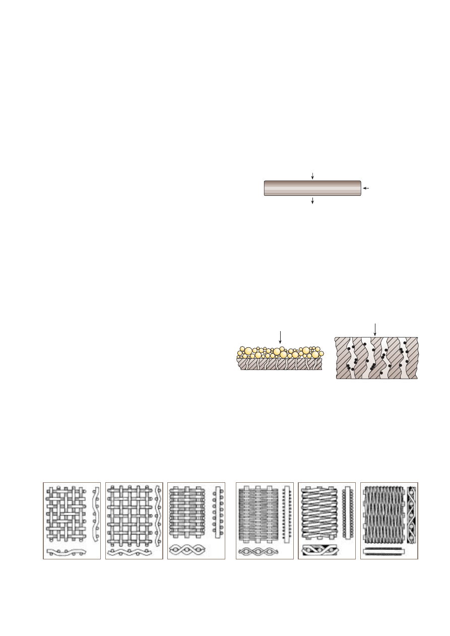
Figure 3 shows examples of filter screen configurations used
on surface filters.
Alfa Laval Marine & Diesel Equipment 5
Alfa Laval Automatic Filters
Fluid with solid particles
Filtrated fluid (Filtrate)
Filter medium
Figure 1. Schematic diagram of a filtration system.
Fluid
Cake of captured particles
Filter medium
Filter medium
Deep-bed filtration
Surface filtration
Fluid
Figure 2. Principles of surface and deep-bed filtration.
Figure 3. Examples of filter cloths.
A
B
C
D
E
F
Due to the different screen configurations, comparisons of
given filter finenesses on different filter screens with one
another are of doubtful value.
The advantage of using a surface filter, rather than a depth
filter, is that the filter screens can be cleaned, thus the filter
can be reused. If the filter is backflushed continuously, the
pressure drop across the filter will remain constant.
In practice, a filter can be retained in operation without
interruption, provided that the backflushing is a part of the
filter construction. If so, the filter is called automatic
backflushing, or just automatic.
How efficiently a surface filter will remove solid particles is a
complex question, because the particles do not have a
regular spherical shape. Particles of different sizes and
shapes could therefore pass through, or be stopped by, the
same square opening, depending on how they enter the filter
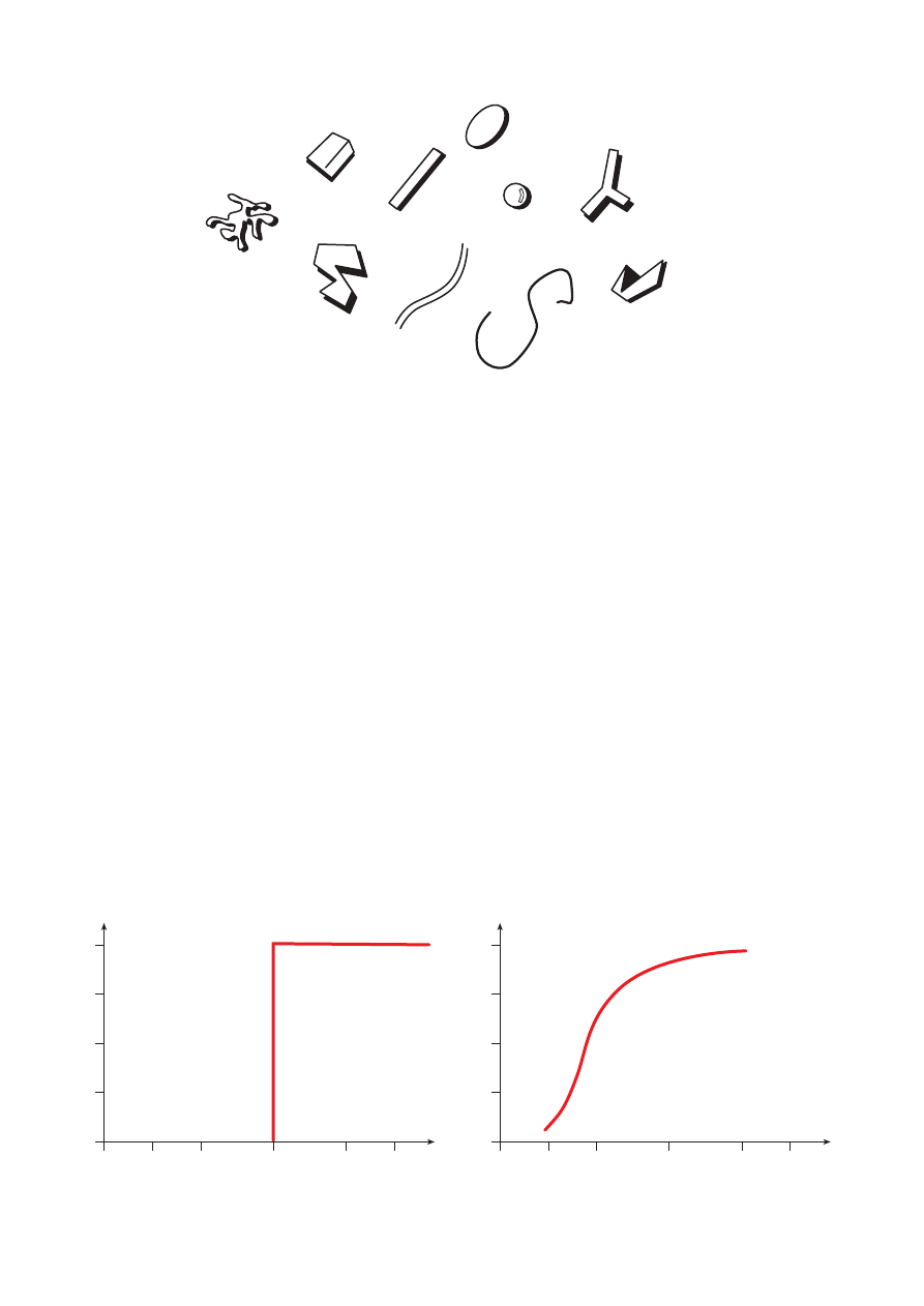
screen. Figure 4 shows some different particle shapes.
If all the particles had a regular spherical shape, the removal
efficiency rate in a filter screen with a square opening of
35 µm would be as shown in Figure 5.
All particles larger than the square opening would be
removed and all particles smaller than the square opening
would pass through.
However, as the particles are not spherical, the question of
whether a certain particle may or may not pass through the
filter screen openings will depend on how the particle
approaches the screen. In practice, particle removal is as
shown in Figure 6.
Alfa Laval Automatic Filters
6 Alfa Laval Marine & Diesel Equipment
Figure 4. Examples of particle shapes.
%
Removal
eff.
100
75
50
25
10
20
50
60
µ
m
0
0
35
%
Removal
eff.
100
75
50
25
10
20
50
60
µ
m
0
0
35
Figure 5. Example of removal efficiency for spherical particles.
Figure 6. Example of removal efficiency for irregularly shaped particles.
Consequently, some particles larger than the square opening
will pass through, and some particles smaller than the square
opening will not.
When comparing surface filters, it is important to specify the
size of the square opening being used. Since particles have
irregular shapes, their ability to pass or not pass through the
filter depends on whether they arrive at the filter screen with
their small end first, or broadside. The term “nominal filter
fineness” has therefore been applied to surface filters.
The term for “absolute filter fineness” (often called “absolute
mesh size”) refers to the square opening, as shown in Figure 7.
In the marine and power industries, the following example is
often cited to clarify the relationship between nominal and
absolute fineness in a surface filter, measuring for example
20 µm nominal filter fineness: 85–90% of all particles larger
than 20 µm are retained in a surface filter with a filter fineness
of 35 µm absolute.
When the same relationship is applied to other filter
finenesses, the following figures are obtained:
• 10 µm nominal → 25 µm absolute
• 20 µm nominal → 35 µm absolute
• 25 µm nominal → 40 µm absolute
• 30 µm nominal → 45 µm absolute
• 35 µm nominal → 50 µm absolute
• 40 µm nominal → 60 µm absolute
However, this does not apply to depth filters. Normally,
particles smaller than the given filter fineness are removed
more efficiently in a depth filter compared to a surface filter
with the same given filter fineness. Therefore, depth filters
might become clogged by these small and harmless
particles, which need not be removed.
Due to difficulties in manufacturing a depth filter with equal
sized pores, it may be less effective for large particles than a
surface filter.
An empirical relationship valid for surface filtration between
filtrate flow (Q), filtrate viscosity (
ν
), filter area (A) and thickness
(
δ
) and differential pressure across the filter (
∆
p) is found to be
Q = K x
A x
∆
p
(1)
υ
x
δ
(K = a constant depending on the permeability of the bed)
The formula describing this relationship, Darcy’s basic
filtration equation, is named after the man who formulated it.
This formula is valid when the differential pressure through the
filter cake is low and the main pressure drop occurs across
the filter medium itself, i.e., when the filter medium is fairly
clean. In these circumstances, the filtrate flow through each
square opening in the filter medium is low, and the flow is
said to be laminar.
If the suspension medium is an absolutely clean liquid, the
cumulative filtrate volume will increase linearly with time, in
accordance with Darcy’s equation. In practice this holds true
at the beginning of the filtration period, but as time passes,
the cumulative filtrate volume tapers off. This is shown in
Figure 8.
When a filter cake begins building up, the simple relationship
expressed by Darcy’s equation is no longer valid, because the
resistance through the filter (K/
δ
in Darcy’s equation) is no
longer constant. The resistance increases as filtration time
increases, and can be written as:
Total resistance = K/
δ
(constant) + R
c
(increasing with time),
where R
c
= resistance through filter cake.
When the filter cake is compressed, the relationship becomes
even more complex.
In this case the resistance through the filter is also a function
of the differential pressure through the filter, i.e., both the
differential pressure and the filter resistance increase during
filtration.
Alfa Laval Marine & Diesel Equipment 7
Alfa Laval Automatic Filters
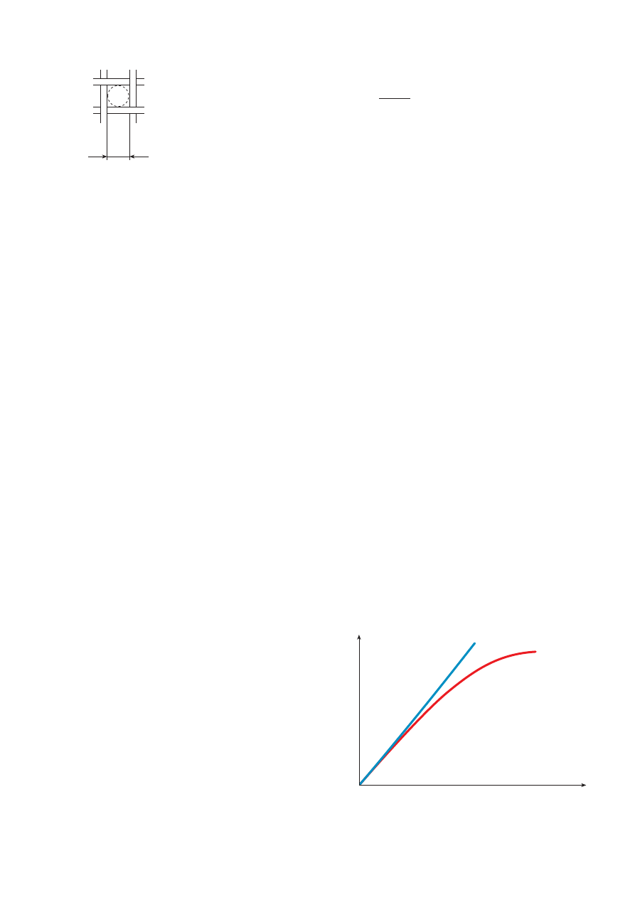
Absolute filter fineness
Time, t
Cumulative filtrate
volume, V
Clean liquid
Suspension
Figure 8. Cumulative filtrate volume as a function of time.
Figure 7. Definition of “absolute filter fineness”.
Alfa Laval Automatic Filters
8 Alfa Laval Marine & Diesel Equipment
Unfiltered
oil
Filtered oil
to engine
Filtered
oil
Unfiltered
oil
Filtered
oil
To lubricating
oil sump
Hydraulic motor
Drain cock
Filtered
oil to
hydraulic
motor
Distributor
Strainer
Full-flow
chamber
Diversion
chamber
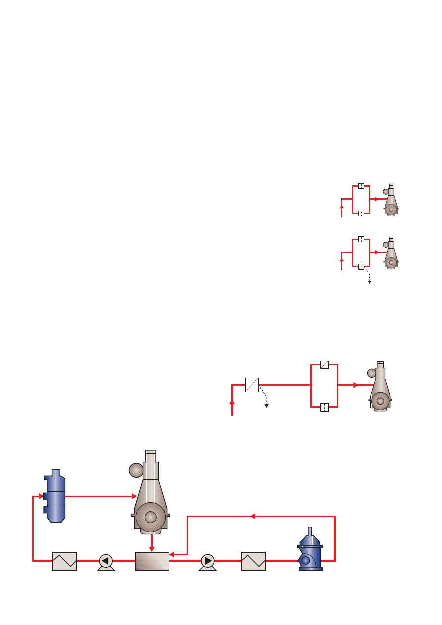
Figure 9. Automatic lubricating oil filter with diversion chamber.
Alfa Laval Marine & Diesel Equipment 9
Alfa Laval Automatic Filters
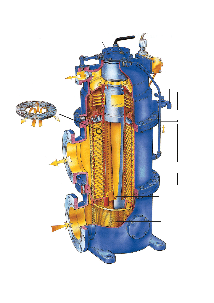
Design
The Alfa Laval filter consists of:
• the filter housing,
• the filtering unit and distributor, and,
• the hydraulic motor.
The filter housing for the automatic filter can have one or two
chambers. The first chamber, where the cleaning of the oil
occurs, is called the full-flow chamber. The second chamber,
where the impurities stopped by the full-flow chamber are
collected, is called the diversion chamber. Cross-sections of
the filter with diversion chamber are shown in Figure 9.
The filter unit contains disc-type filter elements placed on top
of one another forming a very robust filter disc stack. The
construction is designed in such a way that the filter elements
are pressed together not only by rods, but also by the oil
pressure on the end cover at the bottom of the filter stack.
Full-flow and diversion elements are shown in Figure 10.
This construction efficiently prevents leakage of oil between
the filter elements because the elements are pressed more
firmly together as the pressure drop over the filter increases.
A part of a filter disc stack is shown in Figure 11.
The elements are divided into sections by ribs. Together they
form independent filtering columns. The number of filter
elements in the filter disc stack, the diameter of the discs and
the fineness of the filter screen are factors that determine the
capacity of the filter.
The capacity of the Alfa Laval filter system can be further
increased by using a special arrangement of two or three filter
units in parallel.
The filter disc stack, together with sleeve, covers, rods, etc.,
forms a “filtering unit”, in which the “distributor” for the auto-
matic filter is located. The distributor, driven by the hydraulic
motor, in a step-wise manner feeding unfiltered oil to all
columns except one that is open for backflushing. In this
way, each column is backflushed once per rotation of the
distributor (continuous backflushing).
The filter is backflushed approximately once every second
minute, but as the backflushing is always made on at least
one sector, the backflushing flow is continuous.
A filtering unit is shown in Figure 12.
The Alfa Laval filter
Design and operating principle
The Alfa Laval automatic filters are designed specifically for full-flow filtering of fuel
and lubricating oils for trunk piston and crosshead engines.
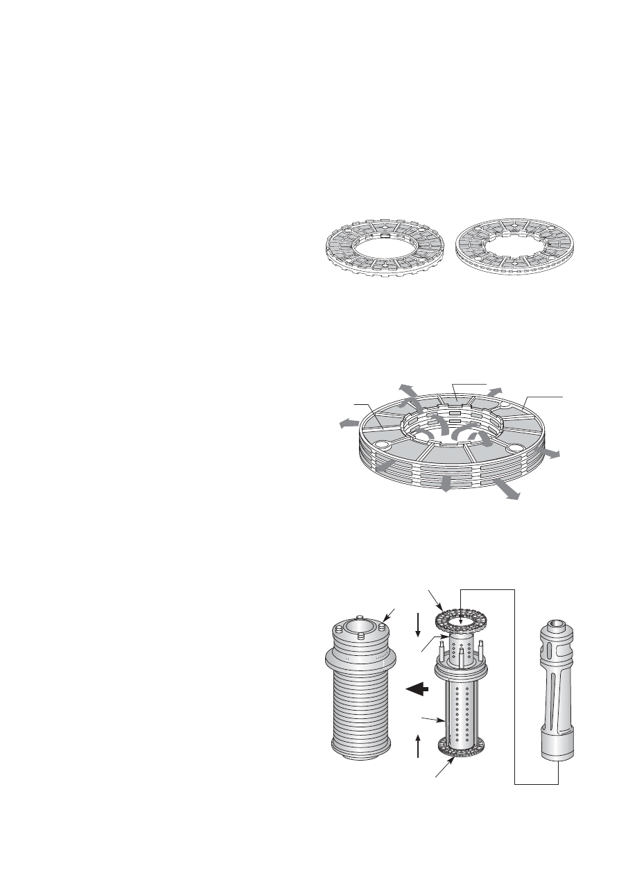
Full-flow filtering element
Diversion filtering element
Figure 12. Filtering unit.
Figure 11. Alfa Laval disc-type filter elements.
Figure 10. Filtering elements.
Filter frame
Distributor
Full-flow elements
Diversion elements
Cover
Sleeve
Rod
Filter cloth
Rib
The filtering unit and distributor are placed in the filter
housing, which, for the automatic filters with filtration of the
backflushing oil, forms two filter chambers:
• the full-flow chamber with full-flow filter elements, where
the harmful solids are removed from the oil flowing towards
the engine
• the diversion chamber with diversion filter elements,
where the backflushed oil is filtered and the solids will be
concentrated and removed from the oil system by periodic
draining.
The distributor is rotated by the hydraulic motor, which in
turn is driven by a small supply of the oil from the outlet of
the filter (approximately 200 l/h).
The hydraulic motor is located on top of the filter housing.
(See Figure 13, which also shows the filter inlets and outlets.)
Features of the Alfa Laval automatic mineral oil filter
• Constant pressure drop during operation due to continuous
backflushing.
• Filter screen is kept clear by continuous backflushing,
which means that long service intervals can be achieved,
without accumulation of particles on filter screen.
• Robust disc-type filter elements.
• Simple installation and operation, without electricity or
compressed air.
• Compact, lightweight design.
Alfa Laval Automatic Filters
10 Alfa Laval Marine & Diesel Equipment
Figure 13. Automatic filter for lubricating oil, with diversion chamber.
Return
Drain
valve
Pressure drop
indicator
Outlet
Inlet
Hydraulic motor
Diversion
chamber
Full-flow
chamber
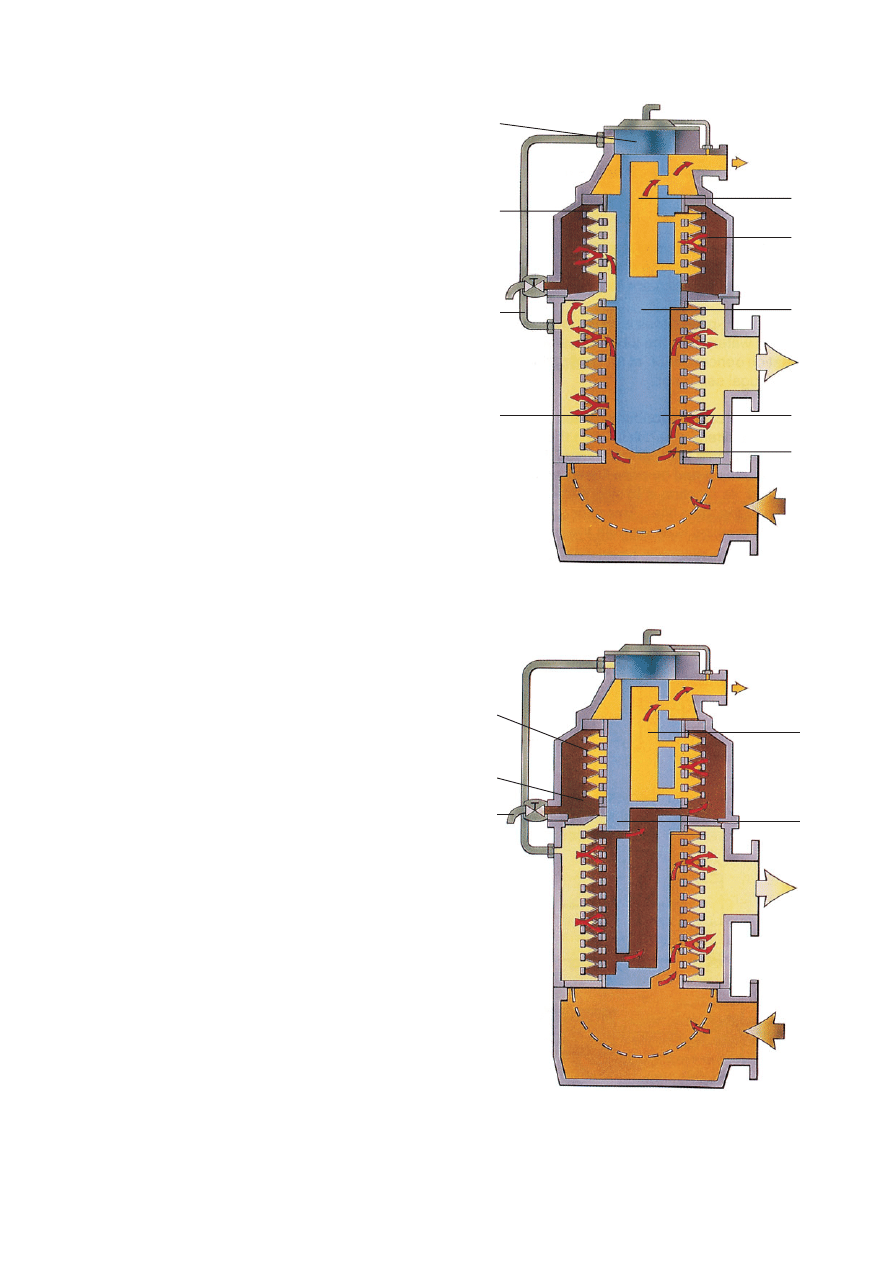
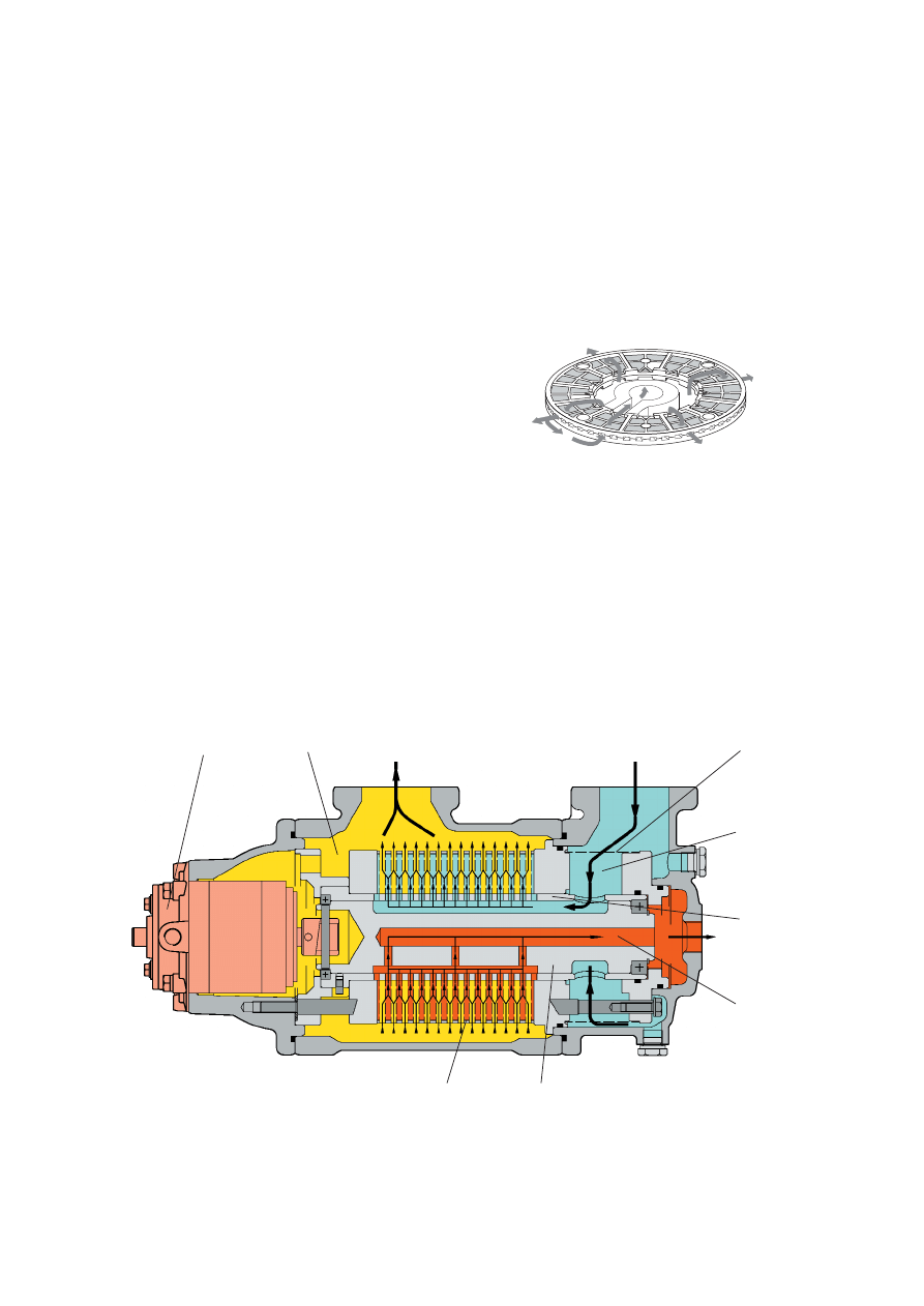
Operating principle,
automatic filter with diversion chamber
The operating principle of an automatic filter is explained
below. (The capital letters in the text refer to Figure 14.)
Phase 1
Filtering in the full-flow chamber
1. Unfiltered oil enters the full-flow chamber of the filter at “A”
and flows into chamber “B” – the space between the
distributor “C” and the inner perimeter of the sleeve where
the filter elements “D” are fitted.
2. From chamber “B” the oil is distributed into and through
the filtering columns formed by elements “D”. The solids
present are trapped.
3. The filtered oil is fed into chamber “E”, where it flows to the
engine through the filter outlet “F”. Approximately 200 l/h
of the filtered oil flows from chamber “E” to the hydraulic
motor “H” through the feed pipe “G” to drive the hydraulic
motor.
Backflushing in the full-flow chamber
4. While the “full-flow” filtration takes place in all columns
except one, solids are removed in one column by back-
flushing, using part of the filtered oil from chamber “E”.
5. The backflushing oil with its solids passes through channel
“K” in the distributor “C” to the diversion chamber “L”.
Filtering in the diversion chamber
6. The backflushing oil passes from diversion chamber “L”
through the diversion filter elements “M” to the passage in
the distributor “N”.
7. Filtered oil is taken back through passage “N” in the
distributor via outlet “P”.
8. In this first phase, no backflushing is performed in the
diversion chamber.
Phase 2
Filtering in the full-flow chamber and diversion chamber
Backflushing in the diversion chamber
In this phase, the distributor has rotated one step compared
with Phase 1.
9. Part of the filtered oil in chamber “E” can now pass
through the channel “R” in the distributor and through the
diversion filter elements “M” (from inside to outside)
removing the trapped particles from the outer side of the
elements.
10. The particles trapped by the filtering elements “M” can
thus settle to the bottom of the diversion chamber “L”.
Removal of the filtered solids
11. The solids filtered out in the diversion chamber are then
discharged from the system by periodic draining by an
automatic or manual valve “V”.
Alfa Laval Marine & Diesel Equipment 11
Alfa Laval Automatic Filters
Figure 14. The flow of oil through an Alfa Laval filter.
N
P
L
K
E
F
C
B
A
H
M
G
D
Phase 1
Phase 2
M
L
V
N
P
R
E
F
A
Alfa Laval Automatic Filters
12 Alfa Laval Marine & Diesel Equipment
Design
The Alfa Laval “Eliminator” filter consists of:
• the filter housing,
• the filtering unit and distributor,
• the hydraulic motor, and,
• the centrifuge.
The first chamber, where the harmful particles are stopped
before they can find their way to the engine, is called the full-
flow chamber. The particles trapped in the full-flow chamber
are driven to the solid bowl centrifuge by backflushing, where
all the particles, even the smallest ones, are trapped on the
centrifuge wall. Clean oil is driven back from the centrifuge to
the oil sump. The centrifuge is driven by the circuit oil
pressure. Cross-section of the filter is shown in Figure 15.
The filtering unit contains disc-type filter elements. Assembled
together they form a robust disc stack. The filtering elements
are divided into sections by ribs. When assembled together,
they form independent filtering columns.
The filter disc stack, together with filter head, sleeve,
distributor, rods and covers, forms the filtering unit. The
distributor, driven by the hydraulic motor, rotates at regular
New filter range
Automatic filter with integrated centrifuge
Figure 15. Automatic lubricating oil filter with centrifuge.
Figure 17. Flow distribution through the full-flow filtering element.
Distributor
Backflushed oil
(to the centrifuge)
Clean oil to
the engine
Unfiltered oil
Figure 16. Full-flow filtering element.
Hydraulic motor
Distributor
Centrifuge
Filtered oil
to the engine
Full-flow chamber
Centrifuge chamber
Unfiltered oil
Filtering unit
Cleaned oil
back to oil sump
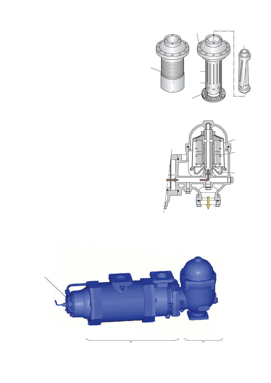
intervals, feeding unfiltered oil to all columns except one, that
is open for backflushing. In this way, each column is back-
flushed once per full rotation of the distributor (continuous
backflushing). A filtering unit is shown in Figure 18.
The distributor is rotated by the hydraulic motor, which is
driven by a small amount of the clean oil downstream the
filter elements. The hydraulic motor is located on the side of
the filter housing (see Figure 20).
The backflushed oil from the full-flow chamber enters the
centrifuge, where a high efficiency axial disc stack separates
the harmful particles from the oil. The particles collect on the
rotor wall. The cleaned oil is ejected through the nozzles,
which give the rotating energy for the centrifuge, then the oil
goes back to the lubricating oil sump by gravity.
(See Figure 19.)
Features of the Alfa Laval “Eliminator” automatic mineral
oil filter
• Constant pressure drop during operation due to continuous
backflushing.
• Contamination level of the oil kept at very low level, thanks
to the high efficiency disc-stack centrifuge.
• Filter screen kept clear by continuous backflushing which
means that long service intervals can be achieved.
• Robust disc-type filter elements.
• Simple installation and operation, without electricity and
compressed air.
• Compact, lightweight design.
Unfiltered oil
Filtered oil
to the engine
Hydraulic
motor
Cleaned oil
back to oil sump
Full-flow chamber
Centrifuge chamber
Alfa Laval Marine & Diesel Equipment 13
Alfa Laval Automatic Filters
Figure 20. “Eliminator” Automatic Filter with centrifuge.
Figure 18. Filtering unit.
Complete
filtering unit
Filtering element
Filter head
Distributor
Rod
Sleeve
Figure 19. Centrifuge chamber.
Backflushed oil
from full-flow
filter
Rotor wall
Axial
disc stack
Nozzles
To lubricating
oil sump
Operating principle, automatic filter
Filtering in the full-flow chamber
1. Unfiltered oil enters the filter at “A” and flows through the
strainer “S” into the chamber “B” – the space between the
distributor “C” and the inner perimeter of the sleeve “J” on
which the full-flow filter elements “D” are mounted.
2. The oil is distributed from this space through the full-flow
filter elements “D” in eleven of the twelve filtering columns
(the twelfth column is being backflushed). The solids are
trapped on the inner side of the elements in the eleven
filtering columns.
3. The filtered oil flows into the full-flow chamber “E” and is
fed through the filter outlet “F” to the engine.
4. A few hundred litres per hour of the filtered oil are routed
from the full-flow chamber “E” to the hydraulic motor “H”
to drive the distributor “C”.
Backflushing in the full-flow chamber
1. While the full-flow takes place in eleven columns, solids
are being removed from the elements in the twelfth column
by backflushing (from outside to inside of the column)
using part of the filtered oil from the full-flow chamber “E”.
2. The backflushed oil with removed solids flow through the
passage “K” in the distributor “C” and is routed to the
centrifuge “W”, where the solids will be removed from the
oil before it goes back to the sump.
Alfa Laval Automatic Filters
14 Alfa Laval Marine & Diesel Equipment
Figure 21. “Eliminator Automatic Filter with centrifuge.
H
E
F
A
S
B
J
W
D
C
Operating principle, centrifuge
Introduction
The purpose of separation is to separate solid particles from
a liquid.
Separation by gravity
A liquid mixture in a stationary bowl will clear slowly as the
heavy particles in the liquid mixture sink to the bottom under
the influence of gravity. A liquid rises, while solids sink.
Continuous separation and sedimentation can be achieved in
a settling tank that has outlets arranged according to the
difference in density. Heavier particles in the liquid mixture will
settle and form a sediment layer on the tank bottom.
Centrifugal separation
In a rapidly rotating bowl, the force of gravity is replaced by
centrifugal force, which can be thousands of times greater.
Separation and sedimentation are continuous and occur
quickly.
The centrifugal force in the separator bowl can achieve in a
few seconds what takes many hours in a tank under
influence of gravity.
Power transmission
The energy necessary to rotate the bowl is taken from the oil
pressure, which rotates the bowl using the force of the
reaction created when the oil passes through the calibrated
nozzles.
Alfa Laval Marine & Diesel Equipment 15
Alfa Laval Automatic Filters
Figure 22. Operating principle.
Figure 23. Separation by gravity.
Figure 24. Centrifugal separation.
Dirty oil
Clean oil
Clean oil
Dirty oil
Nozzle
Alfa Laval Automatic Filters
16 Alfa Laval Marine & Diesel Equipment
General
The complete lubricating oil system of a diesel engine
incorporates a full-flow oil circuit (the main lubricating oil
system) and, for almost all engines operating on residual or
heavy fuel oils, a bypass lubricating oil circuit (the cleaning
system). The oil flow in the cleaning system is approximately
one percent of the oil flow in the main lubricating oil system.
The full-flow circuit contains a lubricating oil filter system
(see Figure 25).
The role of the filter system is to protect the engine from
harmful particles. The entire lubricating oil flow to the engine
passes through the filter system, where the harmful particles
are stopped.
The role of the bypass circuit is to remove harmful conta-
minants (solid particles and water) from the lubricating oil
system in order to keep the contamination concentration at
an acceptable level. This is done by means of the centrifugal
separator.
The filter system contains one main filter, or, if the lubricating
oil flow is high, two or several main filters in parallel. Often
there also is a bypass filter in parallel with the main filter,
which is used if the main filter is stopped.
An indicator or security filter is often installed. Its function is to
stop particles from entering the engine in case of malfunction
of the main filter. This filter (or filters if the oil flow is high) also
indicates if something is wrong with the main filter.
The filter system can be built by using one of the following
three systems:
• Two parallel identical manual filters
(one in use, one on stand-by).
Common on smaller engines
operating on diesel or marine
diesel oil.
• One automatic backflushing filter
as main filter plus one manual filter
as bypass filter (in parallel). Often
there also is a manual filter built on
the engine. This is a common
feature on engines operating on
heavy fuel oil.
• One automatic backflushing filter as main filter, followed by
two parallel manual filters as indicator filters. The two
indicator filters may be built in one unit designated as a
duplex indicator filter. This is a common feature on engines
operating on heavy fuel oil.
Lubricating oil filtration
Filter
system
Lubricating oil sump
Pump
Pump
Cooler
Cooler
Heater
100%
Centrifugal separator
Diesel
engine
Figure 25.
The complete
lubricating oil
treatment system.
Main
filter
Main filter
Indicator filters
Alfa Laval Marine & Diesel Equipment 17
Alfa Laval Automatic Filters
Designation and operation conditions for
Alfa Laval lubricating oil filters
The denomination of lubricating oil filters is built up in the
following manner:
Single or module filter:
Protector
T
280
D
50
/
8
A07
1
2
4
5
6
7
8
Duplex filter:
Protector
T
L
280
D
50
/
8
A07
1
2
3
4
5
6
7
8
1 Generic name for the Alfa Laval filters
2 Type of main filter
T
Automatic filter for Trunk Piston Engines
X
Automatic filter for Crosshead Engines
L
Manual filter
3 Type of secondary filter (if duplex filters only)
T
Automatic filter for Trunk Piston Engines
X
Automatic filter for Crosshead Engines
L
Manual filter
4 External diameter of the filtering elements (automatic filters),
of the filter insert (manual filters).
Dimensions: 120, 140, 150, 240, 280.
5 Type of diversion chamber
–
No diversion chamber
D
Filter with diversion chamber
C
Filter with centrifugal separator
6 Automatic filters: Number of full-flow filtering elements
(total number of elements for module filters).
Manual filters: Filtering area in dm
3
(total surface area of
module filters).
7 Number of diversion elements (if applicable).
8 Filtration code.
Alfa Laval lubricating oil filters can be equipped with different
finenesses of filter screens. The filter fineness is specified by
the engine manufacturer. A sketch of an Alfa Laval lubricating
oil filter installation is shown in Figure 26.
The filter normally has a pressure drop between the oil
entering the filter and the clean oil (P1–P2) of 0.2–0.5 bar.
The amount of filtered oil needed to backflush the filter screen
and drive the hydraulic motor (Q3) is between three and five
percent of the oil entering the filter.
For reliable backflushing and driving of the hydraulic motor, it
is important to have a pressure difference of at least 1.4 bar
for crosshead engines and 2.8 bar for trunk piston engines
between the filtered oil and the oil returning to the sump
(P2–P3).
Diesel
engine
Filter
2
3
Cooler
Lubricating
oil sump
Pump
Stand-by
pump
1
Figure 26. Installation flow sheet for Alfa Laval lubricating oil filter.

Alfa Laval Automatic Filters
18 Alfa Laval Marine & Diesel Equipment
Alfa Laval lubricating oil filters for crosshead engines
The Alfa Laval lubricating oil filters for crosshead engines
differ from those for trunk piston engines. Higher flow rate of
the lubricating oil, different demands on filter fineness,
properties of contaminants, low oil pressure at the inlet to the
engine, etc., are factors that require additional lubricating oil
filter specifications on the part of the engine manufacturer.
Pre-lubrication
In some installations the filter must operate during pre-
lubrication. (The engine is stopped, but the lubricating oil is
pumped with reduced capacity through the engine for rapid
startup.)
This can influence the filtering process. If the pre-lubrication
period is longer than 24 hours and the pressure difference
between the cleaned oil and the return oil to sump (P2–P3) is
less than 0.8 bar, the pressure difference is not sufficient to
operate the automatic filter.
In this case an additional filter has to be installed in a
separate prelubrication circuit.
Dimensioning criteria for
Alfa Laval lubricating oil filters
When dimensioning a lubricating oil filter, parameters such as
filter fineness, fuel oil type (heavy fuel oil or marine diesel oil)
and type of engine (trunk piston engine or crosshead) are
taken into consideration as well as specifications from engine
builders.
The specific load measured as litres of oil per square
centimetre of the effective filter area and hour is presented in
Table 1.
Type of engine
Type of fuel
Specific load
Nom. filter fineness
Abs. filter fineness
(l/cm
2
per hour)
(µm)
(µm)
Trunk piston
Marine diesel oil
6–10
10–30
25–45
Trunk piston
Heavy fuel oil
5–8
10–30
25–45
Crosshead
Heavy fuel oil
10–16
20–35
35–50
Table 1. Specific load (l/cm
2
effective filter area per hour) for lubricating oil filters.
The figures are given in intervals, depending on which filtering fineness is chosen.
Alfa Laval Marine & Diesel Equipment 19
Alfa Laval Automatic Filters
General
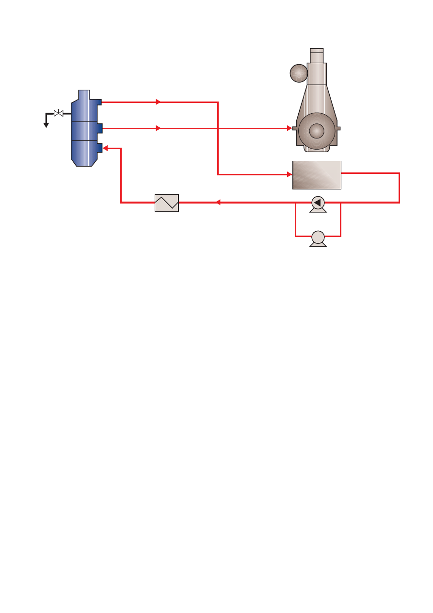
A complete fuel oil treatment system for a diesel engine
consists of a cleaning system, in which the separators are
included, and a conditioning system.
The conditioning system includes filters to remove particles
and impurities that may have entered the system after the
separators. Since the filters are intended to protect the
engine, they should be installed as close to the engine as
possible. An additional filter immediately before the engine is
often included in the engine supply. A typical fuel oil treatment
system for heavy fuel oil is shown in Figure 27.
Some engine builders recommend placing the filter upstream
from the deaerator tank (No. 7 in Figure 27). When the filter is
placed in this position the fuel oil flow through the filter is
smaller, since there is no recirculation of oil as is the case
downstream from the deaerator tank. Also the oil viscosity is
higher since the temperature is lower. Both these factors are
taken into consideration when calculating the throughput
capacities. If the filter is placed upstream from the deaerator
tank, placement of an additional filter downstream from the
deaerator tank is recommended.
For a heavy fuel oil installation, an automatic filter is often
placed in parallel with a manual bypass filter (Figure 28).
Due to the construction principle of the Alfa Laval filter, the oil
pressure into the engine is not affected when the filter is
backflushed.
For fuel treatment installations designed for handling high
viscosity fuels (up to 700 cSt at 50°C), the operating
temperatures for the fuel oil filter can be as high as 160°C
downstream from the deaerator.
Fuel oil filtration
6
7
8
9
1
2
2
3
3
Settling
tank
Service
tank
5
4
FM
2
2
Diesel
engine
1. Feed pumps
2. Heaters
3. Separators
4. Supply pumps
5. Automatic filter
6. Flow meter
7. Deaeration tank
8. Circulating pumps
9. Viscosity transmitter
(Indicator filter is optional)
Figure 27. Fuel oil treatment system with filters situated on the “cold” side. Filters can also be installed on the “hot” side.
Figure 28.
Automatic fuel
oil filter with a
manual bypass
filter (duplex
filter unit).

Alfa Laval Automatic Filters
20 Alfa Laval Marine & Diesel Equipment
Due to the high operating temperatures, the filter is also
available with an electrical motor drive for the distributor
rotation, replacing the hydraulic motor. This motor assembly
is designed specifically for low-speed and high-temperature
operating conditions.
This arrangement provides simplified maintenance and
assures rotation of the distributor even in the most arduous
operating conditions.
The motor can be supplied for 110 or 220 VAC supply, 50 or
60 Hz, and it draws around 0.1A to 0.4A according to filter
size and current during normal operation.
The electrical motor can be upgraded onto existing
installations using a simple upgrade kit available for most
models.
Designation and operating conditions
for fuel oil filters
The denomination of fuel oil filters is built up in the following
manner:
Single or module filter
Protector
F
150
D
E
30
/
12 A05
1
2
4
5
6
7
8
9
Duplex filter
Protector
F
M
150
D
E
30
/
12 A05
1
2
3
4
5
6
7
8
9
1 Generic name for the Alfa Laval filters
2 Type of main filter
F
Automatic fuel oil filter
M
Manual fuel oil filter
3 Type of secondary filter (if duplex filters only)
F
Automatic fuel oil filter
M
Manual fuel oil filter
4 External diameter of the filtering elements (automatic filters),
of the filter insert (manual filters).
Dimensions: 120, 140, 150, 240, 280.
5 Type of diversion chamber
D
filter with diversion chamber
6 Type of driving motor for backflushing
–
Hydraulic motor
E
Electric motor
7 Automatic filters: Number of full-flow filtering elements
(total number of elements for module filters)
Manual filters: Filtering area, in dm
3
(total surface area of
module filters)
8 Number of diversion elements (if applicable)
9 Filtration code
The use of the electrical motor means that this filter is suitable
for “hot” and “cold” side installations, according to customer
requirements and without limitations.
To ensure proper backflushing (and rotation of the hydraulic
motor on the automatic filter when fitted), it is important that
the pressure difference between the filtered oil and the oil
going back to the suction side of the fuel oil pump (P2–P3) is
at least 2 bar. For this reason the viscosity of the fuel oil
should also be below 75 cSt when the filter is placed down-
stream from the deaerator tank (150 cSt upstream from the
deaerator tank). In contrast to the lubricating oil filter, the
hydraulic motor of the fuel oil filter is driven by the filtered oil
from the diversion chamber.
The pressure drop between the unfiltered and filtered oil
(P1–P2) is normally 0.2–0.5 bar. The necessary amount of oil
for backflushing the filter is approximately 15 percent of the
oil flow entering the filter. The same oil that is used for
backflushing is also used to drive the hydraulic motor.
Another factor that influences the sizing of the filter is the
fineness of the filter screen. This is determined by the
requirements of the diesel engine manufacturers. The filter
size for a given fuel flow increases when a smaller filter screen
is used, due to the fact that the number of particles collected
on the filter screen will increase.
Dimensioning criteria for Alfa Laval fuel oil filters
The maximum allowed load for a fuel oil filter depends on
which type of fuel is filtered and filter fineness. Due to the oil
flow, the filter size can roughly be calculated from Table 2
below. Note that the oil viscosity through the filter is less than
75 cSt and that P2–P3
≥
2 bar.
Type of fuel
Specific load
Nom. filter fineness
Abs. filter fineness
(l/cm
2
per hour)
(µm)
(µm)
Marine diesel oil
4–8
10–30
25–45
Heavy fuel oil
upstream 2–3, downstream 3–6
10–30
25–45
Table 2. Specific load (l/cm
2
effective filter area per hour) for fuel oil filters. The figures are given in intervals,
depending on which filter fineness is chosen. (Note! Upstream viscosity
≤
150 cSt. Downstream viscosity
≤
75 cSt, P2–P3
≥
2 bar.)

Alfa Laval reserves the right to make changes at any time without prior notice.
Any comments regarding possible errors and omissions or suggestions for improvement
of this publication would be gratefully appreciated.
Copies of this publication can be ordered from your local Alfa Laval company.
Published by:
Alfa Laval Tumba AB
Marine & Diesel Equipment
SE-147 80 Tumba
Sweden
© Copyright Alfa Laval Tumba AB 2004.

EOEM00012EN 0406
Alfa Laval in brief
Alfa Laval is a leading global provider
of specialized products and engi-
neering solutions.
Our equipment, systems and services
are dedicated to helping customers
to optimize the performance of their
processes. Time and time again.
We help our customers to heat, cool,
separate and transport products
such as oil, water, chemicals, bever-
ages, foodstuff, starch and pharma-
ceuticals.
Our worldwide organization works
closely with customers in almost 100
countries to help them stay ahead.
How to contact Alfa Laval
Contact details for all countries are
continually updated on our web site.
Please visit www.alfalaval.com to
access the information.
www
.fotoskrift.se
Wyszukiwarka
Podobne podstrony:
Efficient VLSI architectures for the biorthogonal wavelet transform by filter bank and lifting sc
file33576 0 EMD00046EN FO
Applications of polyphase filters for bandpass sigma delta analog to digital conversion
Fine Filters CJC
EMI Suppression Filters EMIFIL Nieznany
FILTRY 3, //1) Simple comb filter
No Filter Trade as you see it
Pi filter id 356366 Nieznany
muh 28 5 2 0406 5
File33 2
doc0940 8 Point Moving Average Filter on tinyAVR and megaAVR devices
K filter
Fire Wall oparte na IP Filter
ARRL QST Magazine Clean up Signals with Band Pass Filters (part 1) (1998) WW
Adaptive Filters in MATLAB From Novice to Expert
kalman filter streszczenie
filter ag
Designing Elliptical Filters
kalman filter prezentacja id 23 Nieznany
więcej podobnych podstron