
1484
Research Article
International Journal of Current Engineering and Technology
ISSN 2277 - 4106
© 2013 INPRESSCO. All Rights Reserved.
Available at http://inpressco.com/category/ijcet
Design of Gas Tungsten Arc Welding Power Supply using Power Electronic
Transformer for Steel and AluminiumWelding
R.Shiju Kumar
a
and T.Ruban Deva Prakash
b*
a
Sathyabama University, Chennai ,Tamilnadu India
b
Sree Narayana Gurukulam College of Engineering, Kollenchery, Kerala
Accepted 10 October 2013, Available online 19 October 2013, Vol.3, No.4 (October 2013)
Abstract
Welding power supply is a device that supplies high current at low voltages in the range of 50V. Gas tungsten arc
welding draws low current in the range of 5A. Gas tungsten arc welding machine operates with dc supply for steel
welding and operates with 150Hz rectangular wave ac supply for aluminium welding to avoid oxidation and better
welding quality. Welding power supply has constant current or constant voltage operation. This paper deals with
constant voltage welding power supply. Conventional welding power supplies are transformer style or IC engine/motor
driven generator style or inverter style devices. Harmonics, low power factor and transient disturbance are the major
problems with conventional welding power supply. Recently, power electronic transformer gains importance due to
reduced size and weight in many applications. Traditional power electronic transformer with its power quality analysis
is presented in this paper. This paper also proposes a novel modular power electronic transformer based dc welding
power supply for gas tungsten arc welding of steel. Modular topology based on dc-dc buck converter is used for the
design. Also matrix converter power electronic transformer based ac welding power supply for gas tungsten arc welding
of aluminium is proposed in this paper. DC link in input side is eliminated using 3-phase to 1-phase matrix converter. A
simple control method for the matrix converter is explained in this paper. Performance is validated by simulation studies.
It if found that the input voltage and current has some harmonics, but much less than that of traditional power electronic
transformer topologies.
Keywords: Power quality, welding power supply, power electronic transformer, high frequency transformer, gas
tungsten arc welding, steel and aluminium welding.
1. Introduction
1
A welding power supply is a device that provides an
electric current to perform welding. Welding usually
requires high current (over 80 amperes) and it can need
above 12,000 amperes in spot welding. Low current can
also be used; welding two razor blades together at 5 amps
with gas tungsten arc welding is a good example. A
welding power supply can be as simple as a car battery
and as sophisticated as a modern machine based on silicon
controlled rectifier technology with additional logic to
assist in the welding process. Welding machines are
usually classified as constant current (CC) or constant
voltage (CV); a constant current machine varies its output
voltage to maintain a steady current while a constant
voltage machine will vary its output current to maintain a
set voltage. Shielded metal arc welding and gas tungsten
arc welding will use a constant current source and gas
metal arc welding and flux-cored arc welding typically use
*Corresponding author: T.Ruban Deva Prakash
constant voltage sources but constant current is also
possible with a voltage sensing wire feeder.
The nature of the CV machine is required by gas metal arc
welding and flux-cored arc welding because the welder is
not able to control the arc length manually. If a welder
attempted to use a CV machine to weld with shielded
metal arc welding the small fluctuations in the arc distance
would cause wide fluctuations in the machine's output.
With a CC machine the welder can count on a fixed
number of amps reaching the material to be welded
regardless of the arc distance but too much distance will
cause poor welding. A transformer style welding power
supply converts the high voltage and low current
electricity from the utility mains into a high current and
low voltage, typically between 17 to 45 volts and 55 to
590 amps. A rectifier converts the AC into DC on more
expensive machines. Welding power supplies may also
use generators or alternators to convert mechanical energy
into electrical energy. Modern designs are usually driven
by an internal combustion engine but older machines may
use an electric motor to drive an alternator or generator. In
this configuration the utility power is converted first into
R.Shiju Kumar et al International Journal of Current Engineering and Technology, Vol.3, No.4 (October 2013)
1485
mechanical energy then back into electrical energy to
achieve the step-down effect similar to a transformer.
Since the advent of high-power semiconductors such as
the insulated gate bipolar transistor (IGBT), it is now
possible to build a switched-mode power supply capable
of coping with the high loads of arc welding (Huang. N et
al., 2005). These designs are known as inverter welding
units. They generally first rectify the utility AC power to
DC; then they switch (invert) the DC power into a step-
down transformer to produce the desired welding voltage
or current. The switching frequency is typically 10 kHz or
higher. Although the high switching frequency requires
sophisticated components and circuits, it drastically
reduces the bulk of the step down transformer, as the mass
of magnetic components (transformers and inductors) that
is required for achieving a given power level goes down
rapidly as the operating (switching) frequency is
increased. The inverter circuitry can also provide features
such as power control and overload protection (Khairy
Sayed et al., 2011). The high frequency inverter-based
welding machines are typically more efficient and provide
better control of variable functional parameters than non-
inverter welding machines (Jinhong Zhu et al., 2008). The
IGBTs in an inverter based machine are controlled by a
microcontroller, so the electrical characteristics of the
welding power can be changed by software in real time,
even on a cycle by cycle basis, rather than making changes
slowly over hundreds if not thousands of cycles.
N.R. Mandal explained the distortion created by
welding power supply (Mandal.N.R, 2009). Harmonics,
low power factor and transient disturbance are the major
problems with conventional welding power supply
(ZHANG E.F. de Silva et al., 2011). Power factor
corrected converter based welding power supply is also
proposed in literature (Huang. N et al., 2005 and Khairy
Sayed et al., 2011). Power quality improvement using
three phase modular converter for welding power supply is
proposed by Singh (Singh.B et.al., 2012). Recently power
electronic transformer gains importance due to reduced
size and weight (Hosseini.S.H et al., 2008). It is applied
for electric traction, smart grid, wind electric generation,
ship power supplies, welding power supplies etc (Wrede.H
et al., 2002). Some topologies of power electronic
transformer themselves act as source of power pollution
(Sabahi.M et al., 2009). Power flow control, bidirectional
power flow and power quality mitigation are added
features of power electronic transformers. In this paper we
propose a novel power electronic transformer based
welding power supply for gas tungsten arc welding of steel
and aluminium. Gas tungsten arc welding machine
operates with dc supply for steel welding and operates
with 150Hz rectangular wave ac supply for aluminium
welding to avoid oxidation and better welding quality.
Welding power supply has constant current or constant
voltage operation. This paper deals with constant voltage
welding power supply.
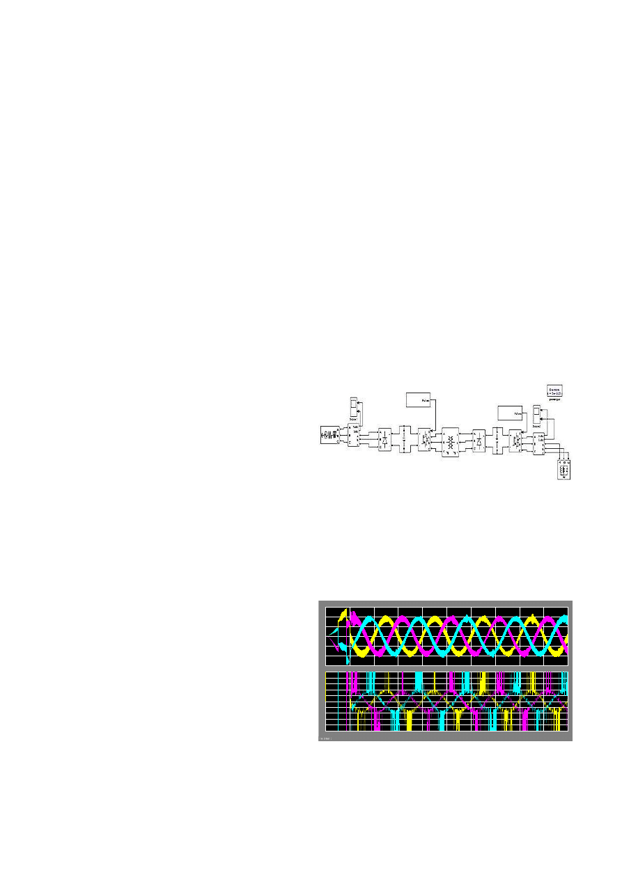
2. Power Electronic Transformer
Power electronic transformer gains importance due to its
reduced size and weight. The principle of power electronic
transformer is converting 50Hz ac to high frequency ac
and given as input to a high frequency transformer and its
output is converted back to 50Hz ac. It gains the advantage
of reduction in size and weight due to high frequency
transformer which also gives galvanic isolation and
voltage transformation. Power flow control, bidirectional
power flow and power quality mitigation are added
features of modern power electronic transformers.
Different topologies of power electronic transformers
are under research. In one approach 50Hz ac is converted
into dc using diode bridge rectifier. The next stage consists
of IGBT 3-leg, 6- pulse inverter which converts dc into 50
KHz ac. In between the two stages there is a dc link
capacitor. A high frequency transformer is used for
galvanic isolation and changing voltage levels. The 50
KHz ac output is converted to dc using diode bridge
rectifier.
This is followed by dc link capacitor and inverter
stage. The IGBT based voltage source inverter converts
the dc to 50 Hz ac. The conventional welding transformer
can be replaced by such power electronic transformer
which reduces size and weight. Also it eliminates the
current unbalance problem. The simulink model of this
power electronic transformer is shown in Fig.1.
Fig. 1. Simulink model of power electronic transformer
3. Power Quality Analysis Of Power Electronic
Transformer
The voltage and current waveform at the input side of the
power electronic transformer explained in section-II is
shown in Fig. 2.
Fig. 2. Input voltage and current of power electronic
transformer
From the figure, it is evident that the transient disturbances
-1.5
-1
-0.5
0
0.5
1
1.5
x 10
4
0
0.01
0.02
0.03
0.04
0.05
0.06
0.07
0.08
0.09
0.1
-0.5
-0.4
-0.3
-0.2
-0.1
0
0.1
0.2
0.3
0.4
0.5
R.Shiju Kumar et al International Journal of Current Engineering and Technology, Vol.3, No.4 (October 2013)
1486
due to high frequency switching are very high especially
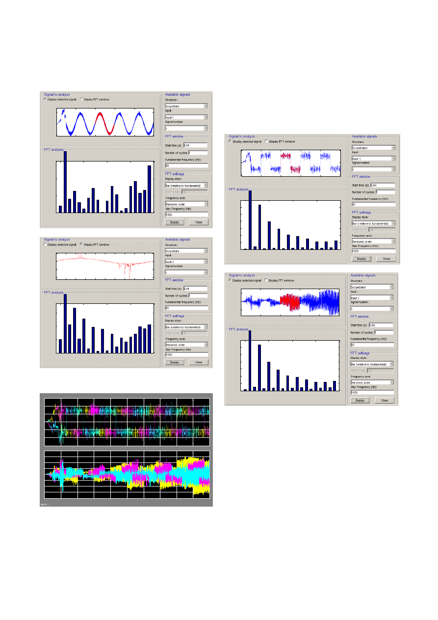
in current waveform. The FFT analysis of the waveforms
is shown in Fig. 3.
Fig. 3. FFT analysis of input voltage and current
Fig. 4. Output voltage and current of power electronic
transformer
The FFT analysis shows that THD of voltage is 2.51%
which is within the limits, but the THD of current is
66.24% which is very high. Thus the traditional topology
of power electronic transformer produces input current
harmonics. The voltage and current at the output side is
shown in Fig. 4. Both voltage and current are non
sinusoidal with very high distortion index (DIN).
The FFT analysis (Fig.5) shows that THD of voltage and
current are 53.65% and 155.59% respectively which are
very high.
Fig. 5. FFT analysis of output voltage and current
Thus the traditional topology of power electronic
transformer produces output voltage and current
harmonics. The above topology of traditional power
electronic transformer can replace the conventional 50Hz
welding transformer but it suffers from power quality
problems. Also this topology requires three phase high
frequency transformer which is costly.
4. Proposed Power Electronic DC Welding Power
Supply
The Gas tungsten arc welding machine operates with dc
supply for steel welding. Welding power supply has
constant current or constant voltage operation. Simulink
model of power Electronic transformer based constant
voltage welding power supply is shown in Fig. 6.
0
0.02
0.04
0.06
0.08
0.1
-1
0
1
x 10
4
Selected signal: 5 cycles. FFT window (in red): 1 cycles
Time (s)
0
5
10
15
20
0
0.005
0.01
0.015
Harmonic order
Fundamental (50Hz) = 8981 , THD= 2.51%
M
a
g
(
%
o
f
F
u
n
d
a
m
e
n
ta
l)
0.04 0.042 0.044 0.046 0.048 0.05 0.052 0.054 0.056 0.058
-1
-0.5
0
0.5
FFT window: 1 of 5 cycles of selected signal
Time (s)
0
5
10
15
20
0
5
10
15
Harmonic order
Fundamental (50Hz) = 0.2153 , THD= 66.24%
M
a
g
(
%
o
f
F
u
n
d
a
m
e
n
ta
l)
-600
-400
-200
0
200
400
600
0
0.01
0.02
0.03
0.04
0.05
0.06
0.07
0.08
0.09
0.1
-20
-15
-10
-5
0
5
10
15
20
0
0.02
0.04
0.06
0.08
0.1
-500
0
500
Selected signal: 5 cycles. FFT window (in red): 1 cycles
Time (s)
0
5
10
15
20
0
5
10
15
20
25
30
Harmonic order
Fundamental (50Hz) = 347.4 , THD= 53.65%
M
a
g
(
%
o
f
F
u
n
d
a
m
e
n
ta
l)
0
0.02
0.04
0.06
0.08
0.1
-10
0
10
Selected signal: 5 cycles. FFT window (in red): 1 cycles
Time (s)
0
5
10
15
20
0
5
10
15
20
25
30
Harmonic order
Fundamental (50Hz) = 2.029 , THD= 158.89%
M
a
g
(
%
o
f
F
u
n
d
a
m
e
n
ta
l)
R.Shiju Kumar et al International Journal of Current Engineering and Technology, Vol.3, No.4 (October 2013)
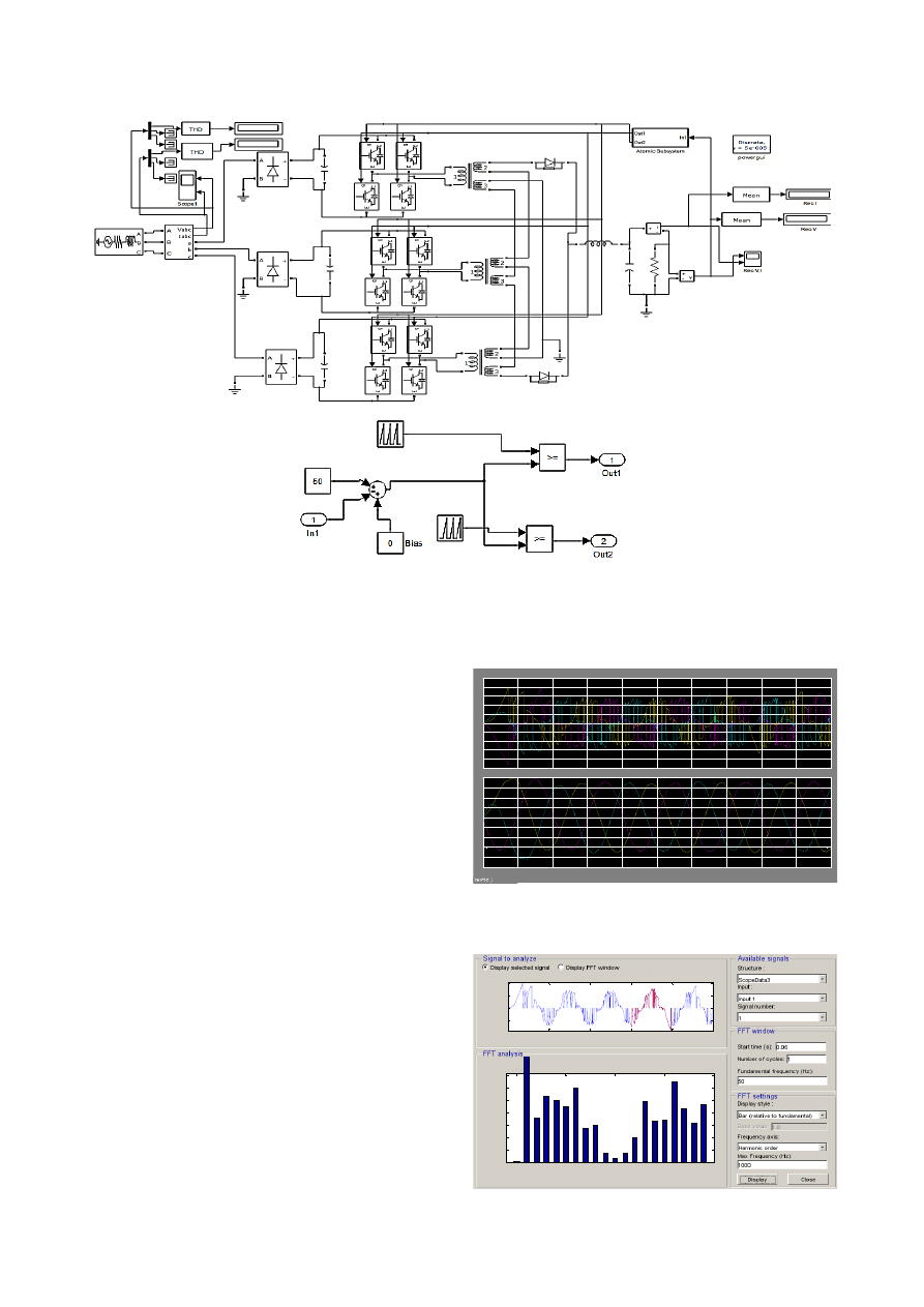
1487
Fig. 6. Simulink model of proposed dc welding power supply
Three phase 50Hz ac supply is the input of the modular
power electronic transformer which is fed from a 3-phase
generator. The power electronic transformer consists of
three single phase diode bridge rectifier. Phase voltages
are fed as input to the rectifiers and the output side of
rectifiers has dc link capacitors. The dc is converted to
high frequency ac using three, 2-leg IGBT inverter. Output
voltage is kept constant at 50V by a closed loop controller
which produces gating pulses for the 2-leg IGBT inverters.
The high frequency outputs from the three inverters are
fed to single phase three winding high frequency
transformers. All the upper secondary windings are
connected in series. One end of the series connected
windings is grounded and the other end has rectifier diodes
which gives rectified output during positive half cycle. All
the lower secondary windings are connected in series. One
end of the series connected windings is grounded and the
other end has rectifier diodes which gives rectified output
during negative half cycle. This dc output is fed to welding
electrodes through series inductor and parallel capacitor.
The topology is similar to dc-dc buck converter if we
exclude the input rectifiers. The output voltage is kept
constant at 50V using a closed loop controller. The
difference between the desired voltage (50V) and the
actual output voltage is compared with a saw tooth
waveform of high frequency to generate the gating pulses
to IGBT inverter.
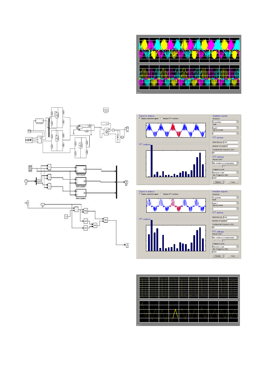
5. Power Quality Analysis of Power Electronic
Transformer Based DC Welding Power Supply
The input voltage and current of proposed welding power
supply is shown in Fig. 7. During the first few cycles
transient disturbances prevails due to switching. The
voltage and current are balanced and the unbalance factor
is zero.
Fig. 7. Input voltage and current of proposed dc welding
power supply
-250
-200
-150
-100
-50
0
50
100
150
200
250
0
0.01
0.02
0.03
0.04
0.05
0.06
0.07
0.08
0.09
0.1
-250
-200
-150
-100
-50
0
50
100
150
200
0
0.02
0.04
0.06
0.08
0.1
-100
0
100
200
Selected signal: 5 cycles. FFT window (in red): 1 cycles
Time (s)
0
5
10
15
20
0
2
4
6
8
10
12
14
Harmonic order
Fundamental (50Hz) = 110 , THD= 48.40%
M
ag
(
%
o
f
F
un
da
m
en
ta
l)
R.Shiju Kumar et al International Journal of Current Engineering and Technology, Vol.3, No.4 (October 2013)
1488
Fig. 8. FFT analysis of input voltage and current
The FFT analysis of input voltage and current are shown
in Fig. 8. The THD of voltage and current are 48% and 2%
respectively which are much less than the THD level in
traditional power electronic transformer. THD of current is
well below the limits specified in IEEE standards.
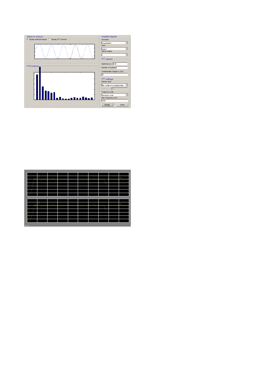
The output voltage and current of proposed welding
power supply is shown in Fig. 9. The output voltage is
kept constant at 50V by the closed loop controller.
Fig. 9. Output voltage and current of proposed dc welding
power supply
6. Proposed Power Electronic AC Welding Power
Supply
Before the advent of inverter-based gas tungsten arc
welding (GTAW) machines, frequency control was rarely
thought of as a way to improve aluminum welding. The
current that came from the wall—50 hertz—was the same
current that went into the weld. Since then countless
manufacturers have sworn off this mentality after seeing
firsthand the benefits of adjustable output frequency. In
alternating current (AC) GTAW, frequency refers to the
number of times that the direction of the electrical current
completes a full cycle every second, expressed in hertz.
Frequency is represented by a sine wave, which depicts
the current flow rising and falling as it reverses direction.
Direct current (DC) cannot be used with nonferrous metals
because of the oxide layer that forms on the surface of the
base material. In direct current electrode negative (DCEN)
GTAW, the current flows from the tungsten electrode to
the work surface, and the positively charged argon gas
ions flow from the work surface to the tungsten. DCEN
works well for steel and other common ferrous metals, but
the oxide layer that forms on nonferrous metals such as
aluminum and magnesium melts at a higher temperature
than the base metal. Trying to weld with this process
causes the base metal underneath the oxide layer to liquefy
while the surface remains hard and impenetrable. Direct
current electrode positive (DCEP) solves the oxide
problem because the current flows from the work-piece to
the tungsten, lifting the oxide off the material in the arc
zone. DCEP alone provides the oxide cleaning action and
very little penetration. Because the heat is concentrated on
the tungsten instead of the work-piece, DCEP also causes
the tungsten to ball up at the end.
AC power supply combines DCEN and DCEP to
provide good heat penetration with cleaning action.
Historically, though, AC has posed an obstacle to GTAW
because the arc frequently extinguishes itself as the current
reaches a zero point before reversing directions. Without
any current passing between the tungsten and the base
metal, the arc simply goes out. Improvements in
transformer-based GTAW machines created the square
wave, which increased the amount of time the arc spends
at full-current flow in both DCEN and DCEP. Square-
wave technology eliminated the tendency for the arc to
extinguish when the current came to a halt as it reversed
directions by making the transition very quickly. This
greatly improved the stability of the arc and made square-
wave technology the preferred method for GTAW of
aluminum and other materials that form an oxide layer,
such as magnesium. The second major revolution in
frequency technology came with the invention of the
inverter, which created the ability to increase or decrease
output frequency beyond the standard 60 Hz, which is the
standard frequency delivered to every outlet in the U.S.
(other countries, such as Germany, England, and France,
deliver AC power at 50 Hz). The inverter also allowed for
the development of the advanced square wave, which
decreases the time it takes for the current to reverse
directions, increasing arc stability even more and
eliminating the need for continuous high frequency (Tae-
Jin Kim et al., 2006). The proposed power electronic ac
welding power supply produces square wave output with
150Hz frequency for better welding quality. The simulink
model of the proposed power electronic ac welding power
supply and its control strategy are shown in Fig. 10. Three
phase 50Hz supply is first converted to 50KHz single
phase ac using 3-phase to 1-phase matrix converter. The
next in the link is the single phase high frequency three
winding transformer. There are two output windings with
same voltage rating. The second terminal of the first
output winding and the first terminal of the second output
winding are connected to the ground. The first terminal of
the first output winding and the second terminal of the
second output winding are connected together through two
rectifier diodes. One diode will be conducting during
positive half cycle and the other diode during negative half
cycle. This is followed by a dc link capacitor and two leg
IGBT inverter which converts the dc to 50Hz ac output.
0
0.02
0.04
0.06
0.08
0.1
-100
0
100
Selected signal: 5 cycles. FFT window (in red): 1 cycles
Time (s)
0
5
10
15
20
0
0.5
1
1.5
2
2.5
Harmonic order
Fundamental (50Hz) = 174.2 , THD= 2.09%
M
ag
(
%
o
f
F
un
da
m
en
ta
l)
0
10
20
30
40
50
60
70
0
0.01
0.02
0.03
0.04
0.05
0.06
0.07
0.08
0.09
0.1
0
2
4
6
8
10
12
14
R.Shiju Kumar et al International Journal of Current Engineering and Technology, Vol.3, No.4 (October 2013)
1489
The control strategy of matrix converter is comparing the
phase voltages with a rectangular wave. The rectangular
wave is generated with the desired output frequency of
matrix converter and magnitude equal to half of maximum
value of nominal phase voltage of input supply. During the
positive half cycle of rectangular wave, gating pulse for
IGBT based bipolar switch is produced when the
corresponding phase voltages are greater than rectangular
wave. During the negative half cycle of rectangular wave,
gating pulse for IGBT based bipolar switch is produced
when the corresponding phase voltages are lesser than
rectangular wave. The bipolar switches of the matrix
converter are realized using one IGBT and four diodes
with configuration shown in Fig.10.
Fig. 10. Simulink model of proposed ac welding power
supply
7. Power Quality Analysis of Power Electronic
Transformer Based Ac Welding Power Supply
The input voltage and current of proposed ac welding
power supply is shown in Fig. 11. The distortion index
(DIN) which is the ratio between the rms value of
harmonic component to rms value of current/voltage is
very high for both voltage and current, but the input power
factor is almost unity.
The FFT analysis of input voltage and current are
shown in Fig. 12. The THD of voltage and current are
56% and 75% respectively which are far above the limits
specified in IEEE standards. Efforts can be taken in future
designs for limiting the same.
Fig. 11. Input voltage and current of proposed dc welding
power supply
Fig. 12. FFT analysis of input voltage and current
Fig. 13. Output voltage and current of proposed dc
welding power supply
-800
-600
-400
-200
0
200
400
600
800
0
0.01
0.02
0.03
0.04
0.05
0.06
0.07
0.08
0.09
0.1
-1.5
-1
-0.5
0
0.5
1
1.5
2
0
0.02
0.04
0.06
0.08
0.1
-500
0
500
Selected signal: 5 cycles. FFT window (in red): 1 cycles
Time (s)
0
5
10
15
20
0
0.5
1
1.5
Harmonic order
Fundamental (50Hz) = 338.7 , THD= 56.88%
M
ag
(
%
o
f
F
un
da
m
en
ta
l)
0
0.02
0.04
0.06
0.08
0.1
-1
0
1
Selected signal: 5 cycles. FFT window (in red): 1 cycles
Time (s)
0
5
10
15
20
0
5
10
15
20
Harmonic order
Fundamental (50Hz) = 0.6844 , THD= 75.68%
M
ag
(
%
o
f
F
un
da
m
en
ta
l)
-50
-40
-30
-20
-10
0
10
20
30
40
50
0
0.01
0.02
0.03
0.04
0.05
0.06
0.07
0.08
0.09
0.1
-0.1
-0.05
0
0.05
0.1
0.15

R.Shiju Kumar et al International Journal of Current Engineering and Technology, Vol.3, No.4 (October 2013)
1490
The output voltage and current of proposed ac welding
power supply is shown in Fig. 13. The output voltage is a
square wave with 150Hz frequency. Thus the welding
quality will be very good for welding aluminium using gas
tungsten arc welding machine.
Conclusion
Harmonics, low power factor and transient disturbance are
the major problems with conventional welding power
supply. It is suggested to replace conventional welding
transformer by power electronic transformer. The power
quality issues in traditional power electronic transformer
are analyzed in this paper by simulation. Traditional
topology of power electronic transformer produces input
current harmonics, output voltage and output current
harmonics. Also this topology requires three phase high
frequency transformer which is costly. Hence this paper
proposed a novel power electronic transformer based dc
welding power supply for gas tungsten arc welding of
steel. Modular topology based on dc-dc buck converter is
used for the design. Also a novel power electronic
transformer based ac welding power supply for gas
tungsten arc welding of aluminium is proposed. DC link in
input side is eliminated using 3-phase to 1-phase matrix
converter. A simple control method for the matrix
converter is explained in this paper. Performance of the
proposed power electronic transformer based welding
power is validated by simulation. However the input
voltage and current are having some harmonics, but much
less than that of traditional power electronic transformer
topology. Efforts can be taken in future designs for
limiting the same.
References
Hosseini.S.H, M. B. Sharifian, M. Sabahi, A. Yazdanpanah, and G.
H. Gharehpetian (May 2008), Bidirectional power electronic
transformer for induction heating systems, in Proc. Can. Conf.
Electr. Comput. Eng., May 4–7,pp. 347–350.
Huang. N, D. Zhang, T. Song, M. Fan, Y. Liu and Y. Zhao (2005), A
10 kW single-stage converter for welding with inherent power
factor correction, in Proc. of IEEE APEC'05, vol. 1, pp. 254-259.
Jinhong Zhu, Shuzhong Song, Hongxin Shi and Kang Yong Lee
(2008), Investigation on control strategies for pulse gas metal arc
welding process, in Proc. of IEEE Industrial Electronics and
Applications (ICIEA), pp. 1276-1281.
Khairy Sayed, Keiki Morimoto, Soon-Kurl Kwon, Katsumi Nishida
and Mutsuo Nakaoka (2011), DC-DC converter with three-phase
power factor correction for arc welder, in Proc. of IEEE ICPE-
ECCE Asia.
Mandal.N.R (2009), Welding Techniques, Distortion Control and
Line Heating, Narosa Publication House Pvt. Ltd., India.
Sabahi.M, S. H. Hosseini, M. B. Sharifian, A. Yazdanpanah, andG.
H. Gharehpetian (Mar. 2009), A three-phase dimmable lighting
system using a bidirectional power electronic transformer, IEEE
Trans. Power Electron., vol. 24, no. 3, pp. 830–837,
Singh.B, Narula.S, Bhuvaneswari.G (Dec 2012), Power quality
improvement using three phase modular converter for welding
power supply, Power India Conference, 2012 IEEE Fifth , pp. 1-6
Tae-Jin Kim, Jong-Pil Lee, Han-Woong, Park Kim and Cheul-U
Kim (2006), Development of a power supply for the pulse MIG
arc welding with a wire melting rate change, in Proc. of IEEE
PESC'06, pp. 1-4.
Wrede.H, V. Staudt, and A. Steimel (2002) Design of an electronic
power transformer, in Proc. IEEE 28th Annu. Conf. Ind. Electron.
Soc., vol. 2, pp. 1380–1385.
Zhang E.F. de Silva, R.M. Jose, A. Scotti and J.C. de Oliveira
(2011), Power quality analysis of gas metal ARC welding process
operating under different drop transfer modes, in Proc. of IEEE
COBEP, pp. 129-135,
A welding power supply is a device that provides an
electric current to perform welding. Welding usually
requires high current (over 80 amperes) and it can need
above 12,000 amperes in spot welding. Low current can
also be used; welding two razor blades together at 5 amps
with gas tungsten arc welding is a good example. A
welding power supply can be as simple as a car battery
and as sophisticated as a modern machine based on silicon
controlled rectifier technology with additional logic to
assist in the welding process. Welding machines are
usually classified as constant current (CC) or constant
voltage (CV); a constant current machine varies its output
voltage to maintain a steady current while a constant
voltage machine will vary its output current to maintain a
set voltage. Shielded metal arc welding and gas tungsten
arc welding will use a constant current source and gas
metal arc welding and flux-cored arc welding typically use
constant voltage sources but constant current is also
possible with a voltage sensing wire feeder.
The nature of the CV machine is required by gas metal arc
welding and flux-cored arc welding because the welder is
not able to control the arc length manually. If a welder
attempted to use a CV machine to weld with shielded
metal arc welding the small fluctuations in the arc distance
would cause wide fluctuations in the machine's output.
With a CC machine the welder can count on a fixed
Wyszukiwarka
Podobne podstrony:
2003 08 25 1490
1490
450 1490
MPLP 3 Styczeń 1490;391wp
1490
Rozp. z 17.11.10- 1487 i 1490, Specjalne potrzeby edukacyjne, Podstawa prawna
MPLP 3 Styczeń 1490;391yh(1)
1490
1490 1789
Komisja NDSiNDN Dz U 08 225 1490
1490
2003 08 25 1490
1490
Wojciech Radzki Strój męski i wyposażenie 1450 1490
Wojciech Radzki Strój męski i wyposażenie 1450 1490
M Wilamowski Mikołaj Stadnicki h Drużyna ok 1446 1490, kasztelan przemyski, wojewoda bełski
więcej podobnych podstron