ADVAC
®
- Advanced Design Vacuum Circuit Breakers
Technical Guide

ADVAC, Advance, R-ADVAC and SafeGear are registered trademarks of ABB Inc.
KIRK Key Interlock is a registered trademark of Controlled Power Corp., Massilon, OH.
UL is a registered trademark of Underwriters Laboratory Inc.
Galvalume is a registered trademark of BIEC International.
In the course of technical development ABB reserves the right to change designs without notice.
1
Introduction
C
O
N
T
E
N
T
S
41
REFERENCE
Ratings, technical data, and basic dimensions for ADVAC circuit
breakers and OEM components. Detailed drawings are provided
separately.
27
TECHNICAL SPECIFICATIONS
The basic design and functional requirements for vacuum circuit
breakers and metal-clad components, to assist in the specifica-
tion of switchgear with superior safety, reliability and maintain-
ability.
PRODUCT DESCRIPTION
A detailed description of ADVAC circuit breakers and metal-
clad switchgear components. This section includes pictures and
illustrations to describe product features, functions and benefits,
as well as general information for OEM applications.
5
2
2
INTRODUCTION
Welcome to the ADVAC OEM program, which offers
switchgear assemblers the technology, value, flexibility and
quality needed to succeed in the demanding power distribution
industry.
2
Introduction
The ADVAC OEM
program . . .
the right choice
for your business
The power distribution business is competitive and demanding.
Switchgear customers insist on high quality products with increasingly
fast deliveries and competitive prices. Owners and operators expect
metal-clad switchgear to meet demanding requirements for safety, ease of
operation, and minimum maintenance over a long life. They expect the
latest technology to help them meet these immediate needs, while also
anticipating changes in industry standards, operational resources, and
other critical areas.
To meet these requirements, manufacturers of complex, custom
switchgear must have a dependable supplier of circuit breakers and
components. They need value, flexibility, quality and a partner with the
technology to help them - and their customers - succeed in today's
business environment.
Introduction
ADVAC - Advanced Design Vacuum Circuit Breakers
3
Introduction
ADVAC OEM cells provide switchgear manufacturers with the best
value in the industry — with features that create the ability to focus on
areas of optimum value added, plus one-stop shopping from a complete
library of standard, economical building blocks. For example, circuit
breaker compartments are shipped with guide rails, shutters, primary and
secondary disconnects, and all other critical components factory-installed
and aligned. Thoughtful features add more value: ample room for
terminal blocks and secondary wiring; grounded steel paths for control
wiring inside the compartment; secondary leads pre-wired to terminal
blocks, and more.
Superior Value
The Supplier of
Choice is ABB
The Latest
Technology
ADVAC circuit breakers and metal-clad switchgear components
offer the benefits of the latest technology in medium voltage
vacuum circuit breakers. A modular system of switchgear building
blocks provides superior value, flexibility and quality to switchgear
assemblers. And the ABB OEM program is founded on a commit-
ment to outstanding customer service and the best reputation in
the industry for long term product support.
ADVAC advanced design vacuum circuit breakers feature the latest
technology in vacuum interrupters and operating mechanisms, resulting
in outstanding reliability and maintainability. The incredibly simple
mechanism, the first designed specifically for modern vacuum interrupt-
ers, is the only new mechanism from any supplier in well over a decade.
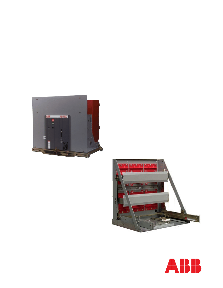
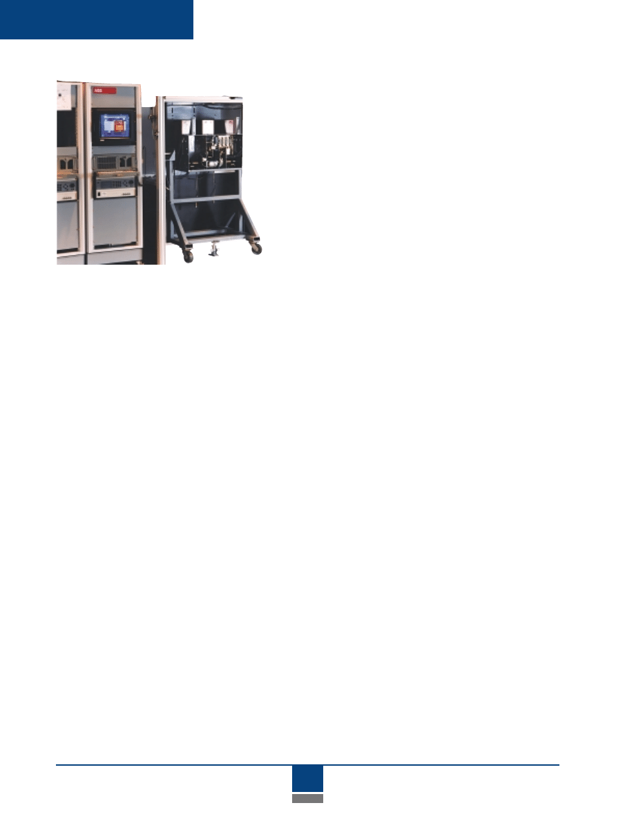
ADVAC circuit breakers, OEM cells,
L-Frames and Parts Kits provide
switchgear assemblers the best
value in the industry.
4
Introduction
Flexibility
The ADVAC breaker and switchgear components have been
subjected to rigorous ANSI design tests. Rugged, self-supporting bolted
module construction provides consistent alignment and enables easy
assembly and adjustment. Rigid hem-bending provides a total of four
layers of steel where adjacent modules are bolted together. Modules are
suitable for use in switchgear that has been seismically certified for UBC
Zone 4. And each ADVAC circuit breaker is automatically tested and
cycled 300 operations prior to shipment.
Quality You Can
Depend On
You can count on ABB for
technology leading products –
plus
the value, flexibility and
quality you need for
your business.
A wide array of primary compartment modules can be stacked in a
variety of arrangements to meet virtually any application, with compact
footprints that reduce floor space and installation costs. Top or bottom
entry of both primary and control wiring add versatility. The wide choice
of primary modules, coupled with ABB value-added features and quick
bolt-together construction, create the flexibility to quickly order and
receive building blocks that can be efficiently configured to meet shorter
lead times for complete systems. This means greater flexibility for you -
and for your customers.
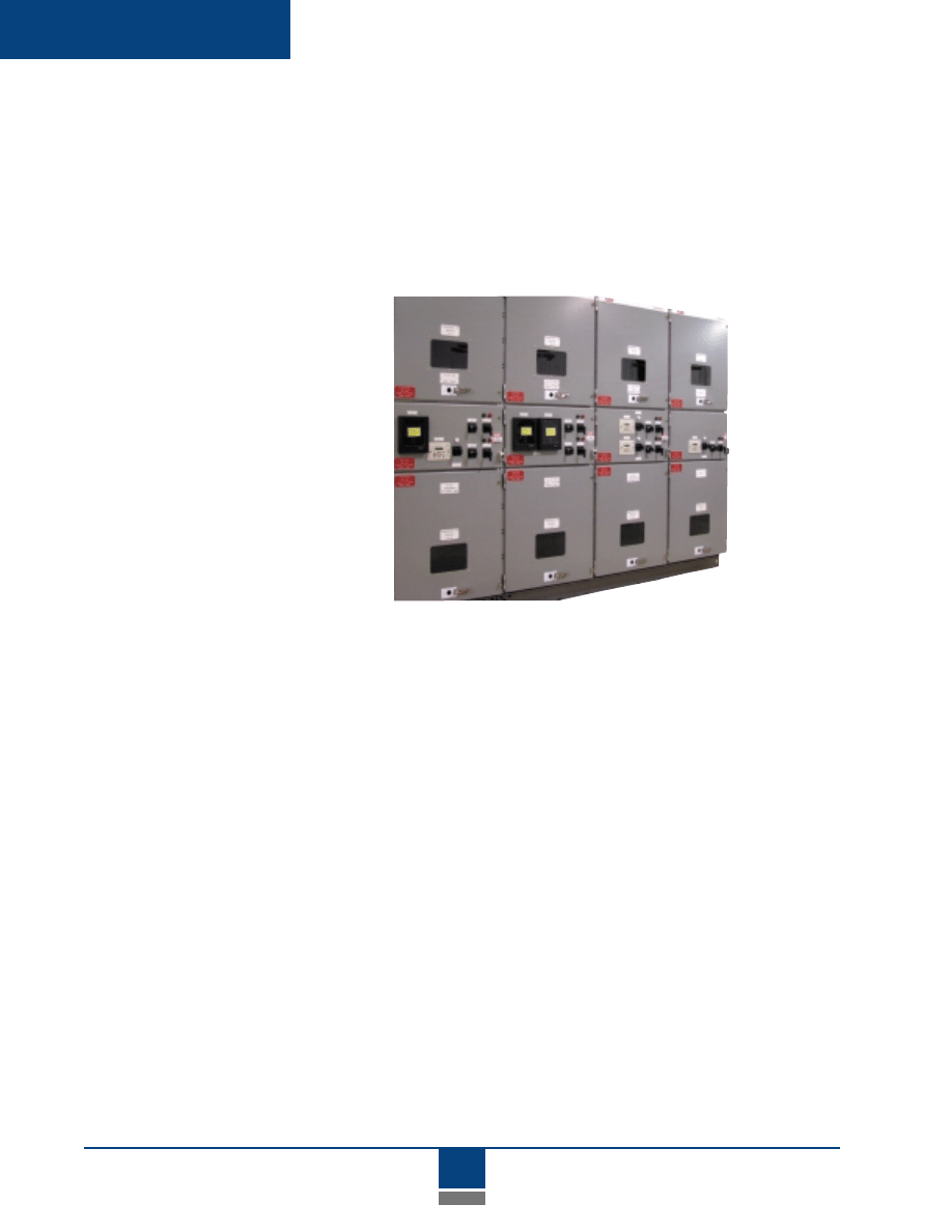
ADVAC circuit breakers are
automatically tested and
cycled 300 operations
prior to shipment.
5
Product Description
PRODUCT
DESCRIPTION
ADVAC Circuit Breakers ................................... 6
Cell Interface and Racking ........................... 1 0
Modular Construction .................................... 1 4
Circuit Breaker Modules ............................... 1 8
Auxiliary Primary Equipment ...................... 2 0
Low Voltage (Instrument) Modules ............. 2 2
Primary Bus System ....................................... 2 3
Accessories ...................................................... 2 4

6
Product Description
ADVAC - Advanced Design Vacuum Circuit Breakers
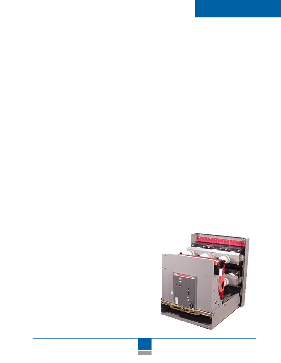
The ADVAC series of vacuum circuit breakers is a complete line
of ANSI-rated circuit breakers offering power distribution system
customers the advantages of the latest vacuum circuit breaker
technology — technology that reduces ownership costs through
improved reliability and maintainability.
Ratings
ADVAC is available in the full range of ANSI ratings through 15 kV,
with interrupting ratings to 1000 MVA and continuous currents
through 3000 A (self-cooled). A complete table of breaker types
and ratings is provided in the Reference Section.
Operating
Mechanism
ADVAC uses a simple, front-accessible stored-energy operating mechanism
designed specifically for use with vacuum technology. This provides the
benefits of dependable vacuum interrupters with advanced contact design
and proven reliability, without the complexity of mechanisms and linkages
found in previous generation circuit breakers.
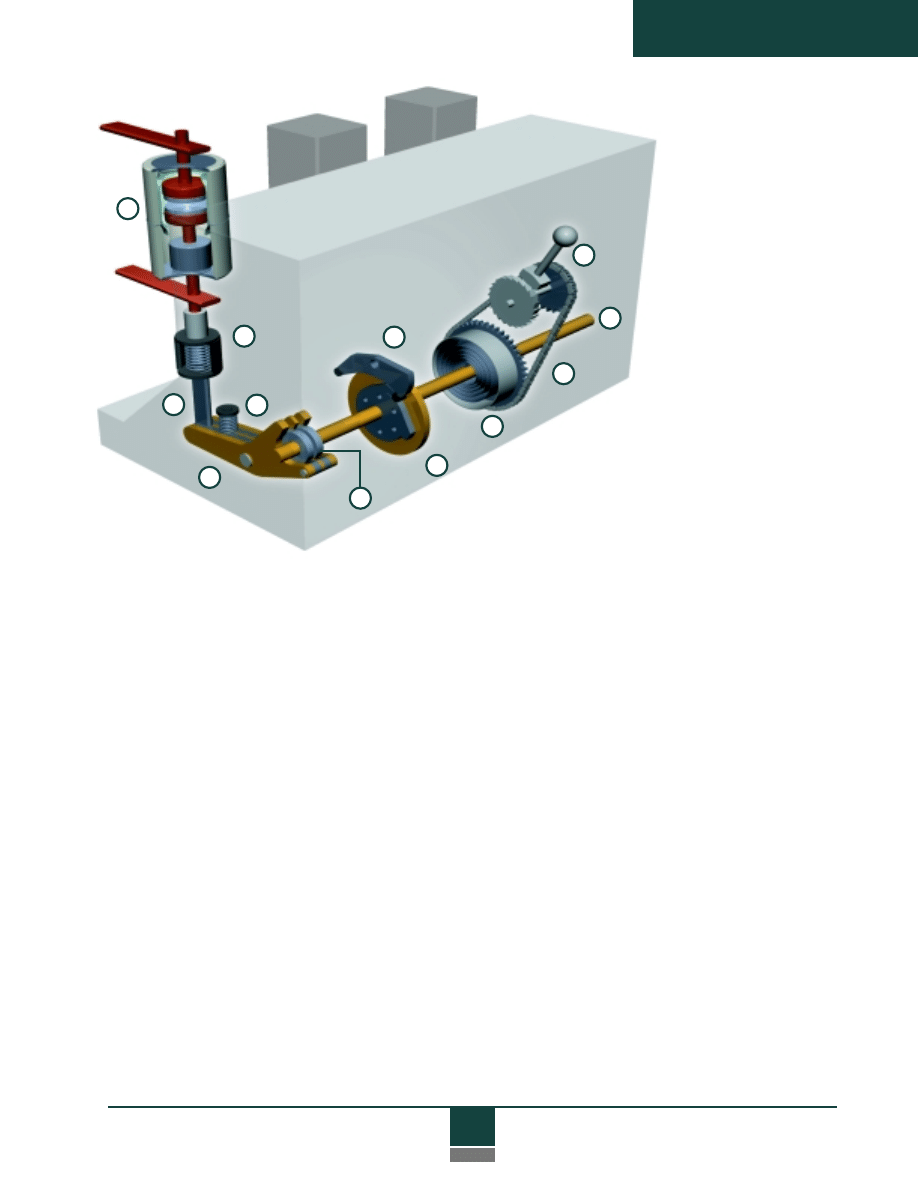
The unique ADVAC mechanism uses a single toroidal spring (1) mounted
on a drive shaft (2) to rotate the shaft in the same direction during opening
and closing. The spring can be charged manually via the chain drive (3) and
ratchet wheel (4) , or electrically by the spring charging gear motor (not
shown in this view). Three sets of precision cams (5), one for each phase,
are mounted on the drive shaft. The cams operate moving stems on
vacuum interrupters (8) through insulating pushrods (7) and direct-acting
rocker arms (6) that convert the rotational force to linear force, accelerating
and decelerating interrupter contacts at optimum speeds during both
opening and closing operations.
The cam shape is designed for the small contact travel required by vacuum
interrupters, and when used with the toroidal spring, this provides much
more efficient movement than the complex linkages and springs used on
conventional breakers. Cam design is critical, as it determines proper contact
speed and momentum. This is an important advantage because it avoids
excessive force that could cause premature wear on both the contacts and
the operating mechanism.
Product Description
ADVAC
Circuit Breakers
7
Product Description
1
2
3
11
4
12
9
6
7
10
8
5
During closing, the shaft rotates
the cams 270
°
to build momen-
tum for the proper closing force
needed to counteract magnetic
repulsion of contacts as the breaker
closes. Also during closing, upward
movement of the rocker arm charges primary
opening springs (9). These are compression type
springs at the back of the breaker, mounted between the
chassis and rocker arm. Compression-type wipe springs (10)
mounted on the pushrods maintain contact pressure once the rocker arms
are locked in the closed position. The cams are stopped precisely at the 270
°
position by a “stop disk” (11) on the rotating shaft. The stop disk locks
main shaft rotation, cams, rocker arms, pushrods and contacts in the
closed position.
A trip signal releases a trip latch (12), which in turn allows the shaft
to complete its rotation back to the full 360
°
position. Shaft move-
ment is aided by the remaining charge on the toroidal spring.
However, the principle operating force is provided by the primary
compression springs on each phase, which are now free to dis-
charge because of the release of the main shaft, rocker arms and
pushrod. A third, but minimal opening force is provided by the
preloaded wipe (compression) springs on the pushrods, although
these springs are primarily used to maintain contact pressure.
This simple concept uses only a small fraction of the
moving parts found in conventional breakers, resulting in
maximum reliability over a longer life — with added savings
from easy, infrequent maintenance.
ADVAC Operating System
8
Product Description
Control System
Control features of the ADVAC breaker emphasize convenience, maintain-
ability and flexibility. Charge, close and trip functions can be accomplished
both electrically and manually. All manual functions can be performed with
great ease at the front of the breaker. Standard operator control features are
shown below.
Control flexibility is the result of a wide range of standard and
optional features, including independently selectable voltages
for electric charge, close and trip functions. Eight auxiliary switch
contacts (4 “a”, 4 “b”) are mounted on-board and wired through
the automatic secondary disconnect. A single schematic diagram (page 48)
shows all standard control features, regardless of control voltage.
Several options are available with an additional secondary discon-
nect, to offer a high degree of flexibility in control system design.
Options include dual isolated shunt trip coils, a direct-acting
undervoltage release, and nine extra on-board contacts for a total of
17 auxiliary contacts (9 “a”, 8 “b”). Since all auxiliary contacts are
on-board, they operate whenever the breaker operates in either
Test or Connected positions.
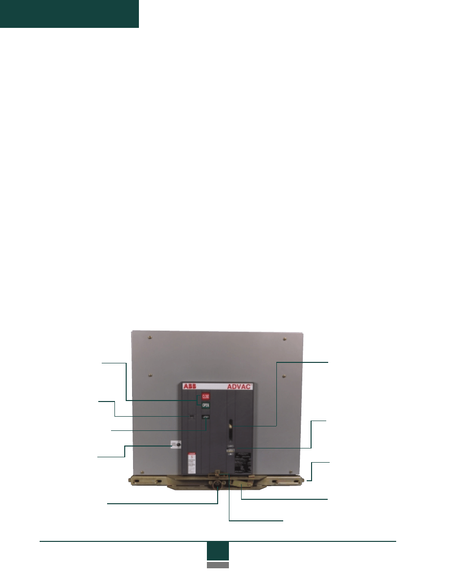
Manual spring
charge port
Spring charge
status indicator
Cell locking tabs
and handles
Racking release lever
Racking padlock provision for
lockout and safety procedures
Manual open and
close push buttons
Non-resettable
operations counter
Open/closed indicator
Charging motor
disconnect switch
Racking access port
Front view of ADVAC circuit breaker
9
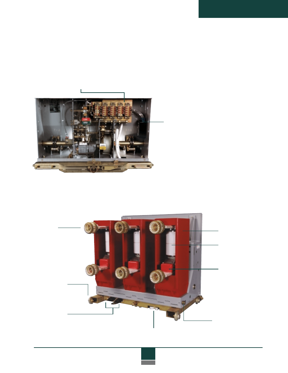
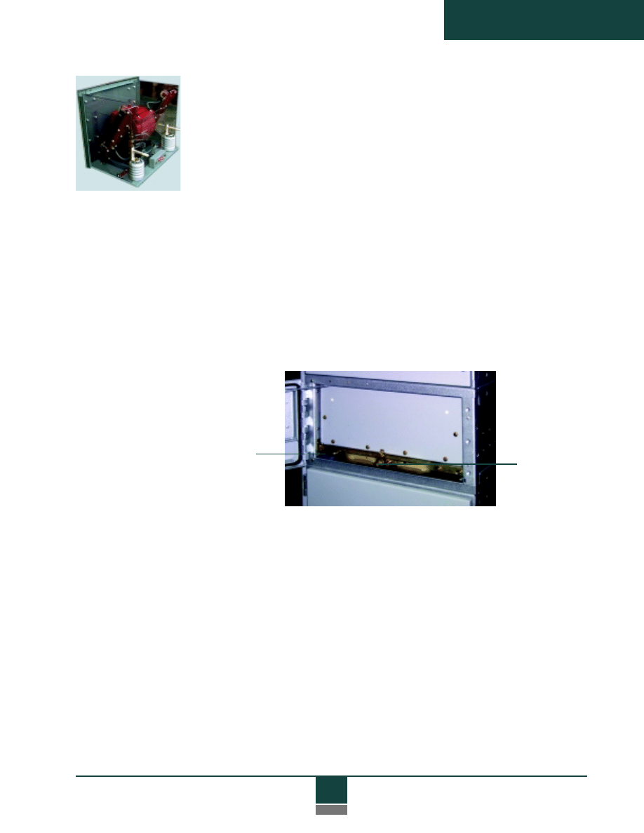
Product Description
ADVAC breaker with front panel
removed shows convenient access
to the simple operating mechanism
and control components.
The ADVAC control system reduces ownership costs through
greatly simplified inspection and maintenance procedures. The entire
operating mechanism and its control components are front accessible.
Modular construction and the use of common components result in fewer
spare parts, and the entire control package is removable for easy mainte-
nance and functional changes.
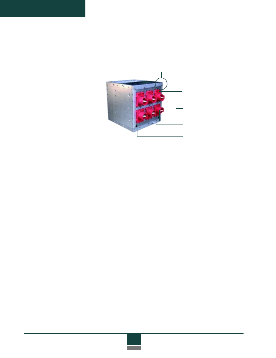
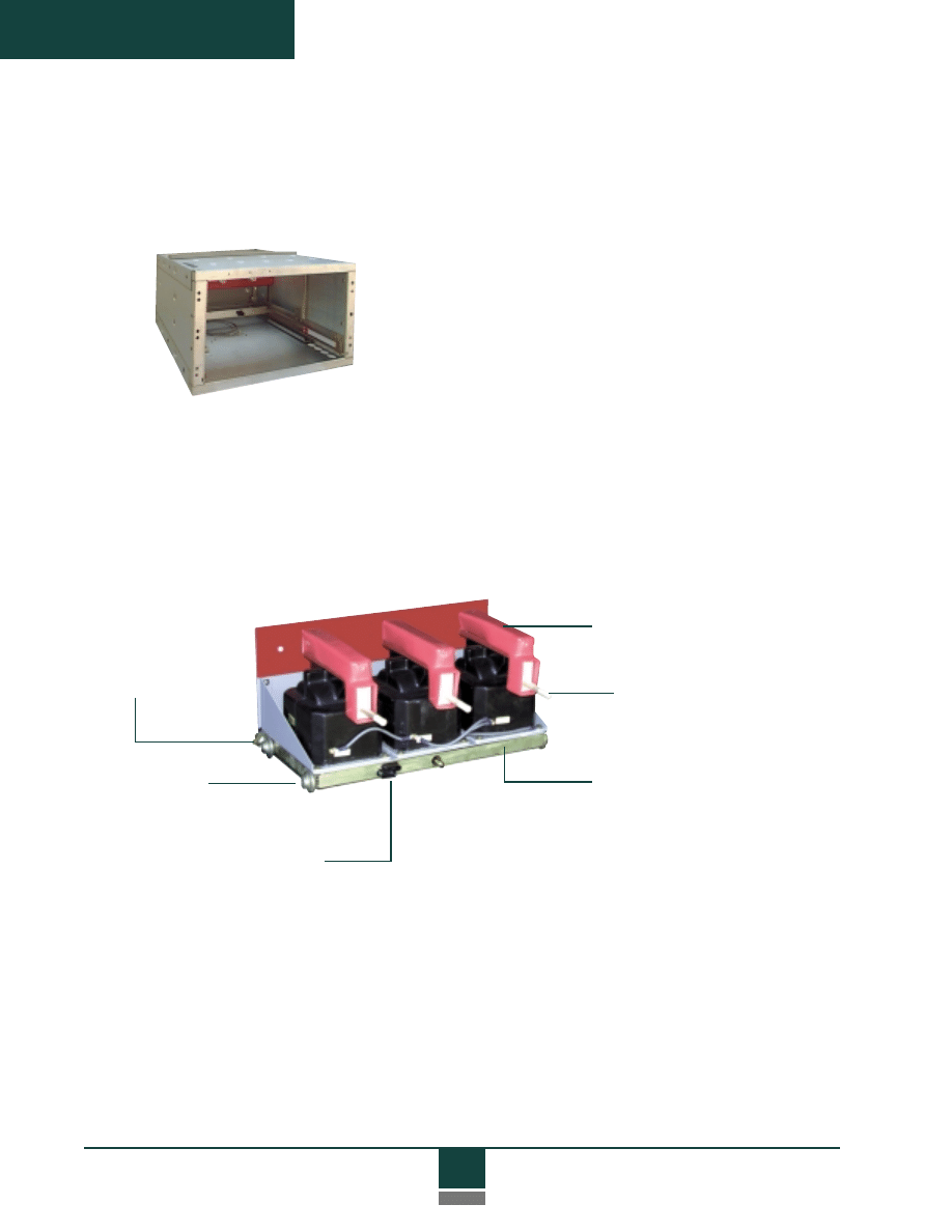
Primary
disconnects
Integral wheels
Secondary
disconnect and
alignment tab
Rear view of ADVAC circuit breaker
Interrupter supports
Vacuum interrupters
Flexible current
transfer to
moving stem
Shutter actuator
Ground contact
Extensive on-board auxiliary
contacts eliminate cell-
mounted mechanism
operated (MOC) auxiliary
switches and related me-
chanical linkages that often
require adjustment on
conventional breakers.
A solid state control device replaces the
conventional anti-pump relay. This improves
reliability and eliminates field adjustments.
10
Product Description
Cell Interface
and Racking
The ADVAC breaker-cell interface is designed for maximum
operator safety by providing three-position, closed door racking with self-
aligning, fully automatic primary and secondary contacts. The racking
system is integral to the breaker, so moving parts can be inspected and
maintained outside the breaker compartment and away from energized
primary and secondary circuits. ADVAC breakers have self-contained
wheels for convenient floor maneuvering. Breakers are easily inserted and
withdrawn from compartments using a lift truck with positive cell docking
for safety.
The simple racking system is operated manually using a standard 16 mm
socket drive. Each of the three distinct compartment positions has a
positive stop. Deliberate operator action is required to release the breaker
for racking from any of these positions.
• Disconnected — Primary and Secondary (control)
contacts disengaged
• Test — Primary contacts disengaged, Secondary
contacts engaged for electrical operation
• Connected — Primary and Secondary contacts engaged
and ready for operation
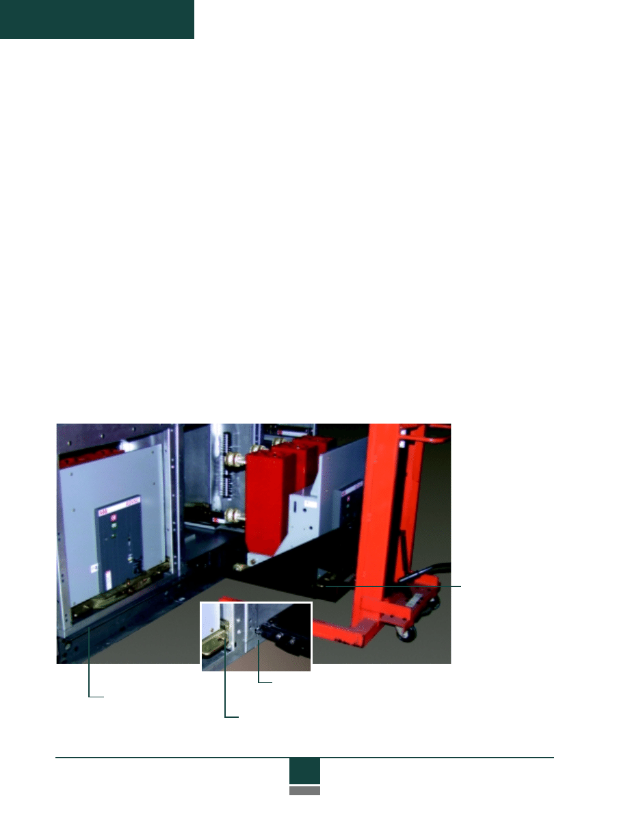
Breaker in
Disconnect
position
Tabs secure breaker
to lift device for safe
handling
Lift truck alignment tabs
docking to switchgear frame
Handle spring-loaded to outboard position,
securing locking tab into guide rail
ADVAC breaker on lift truck

11
Product Description
The racking system also includes all interlocks necessary for
proper sequencing and operation. An ADVAC breaker cannot be
racked while contacts are closed, a breaker cannot be closed when
in an intermediate position, and an improperly rated breaker cannot
be inserted into a cell. The breaker also cannot be moved to the
Connected position unless secondary contacts are engaged. A
standard padlock provision can be used to support lock-out and
tag-out procedures by preventing racking in any position.
Since the racking system is fully automatic, engagement and
disconnect of both primary and secondary contacts are completely
sequenced and driven by the racking operation, even with the
compartment door closed. No manual intervention is required.
Primary shutters automatically cover primary contacts when the
breaker is not in the Connected position. The shutters, which may
be of grounded metal or insulating polycarbonate material, are
actuated simultaneously from both sides of the breaker for smooth,
balanced operation that eliminates binding. Metallic shutters are
grounded by dedicated wiring rather than through mechanical
linkages. An interlock prevents accidental opening of the shutters.
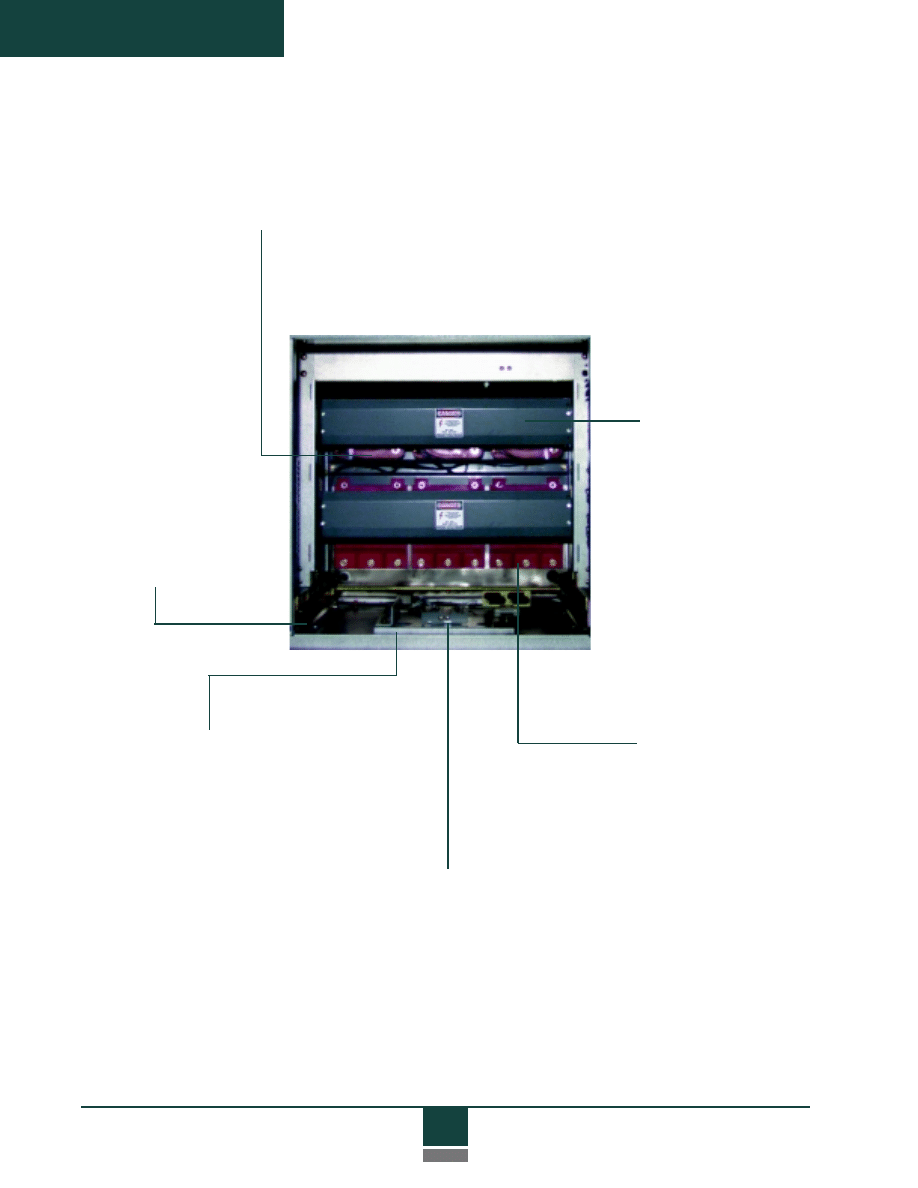
12
Product Description
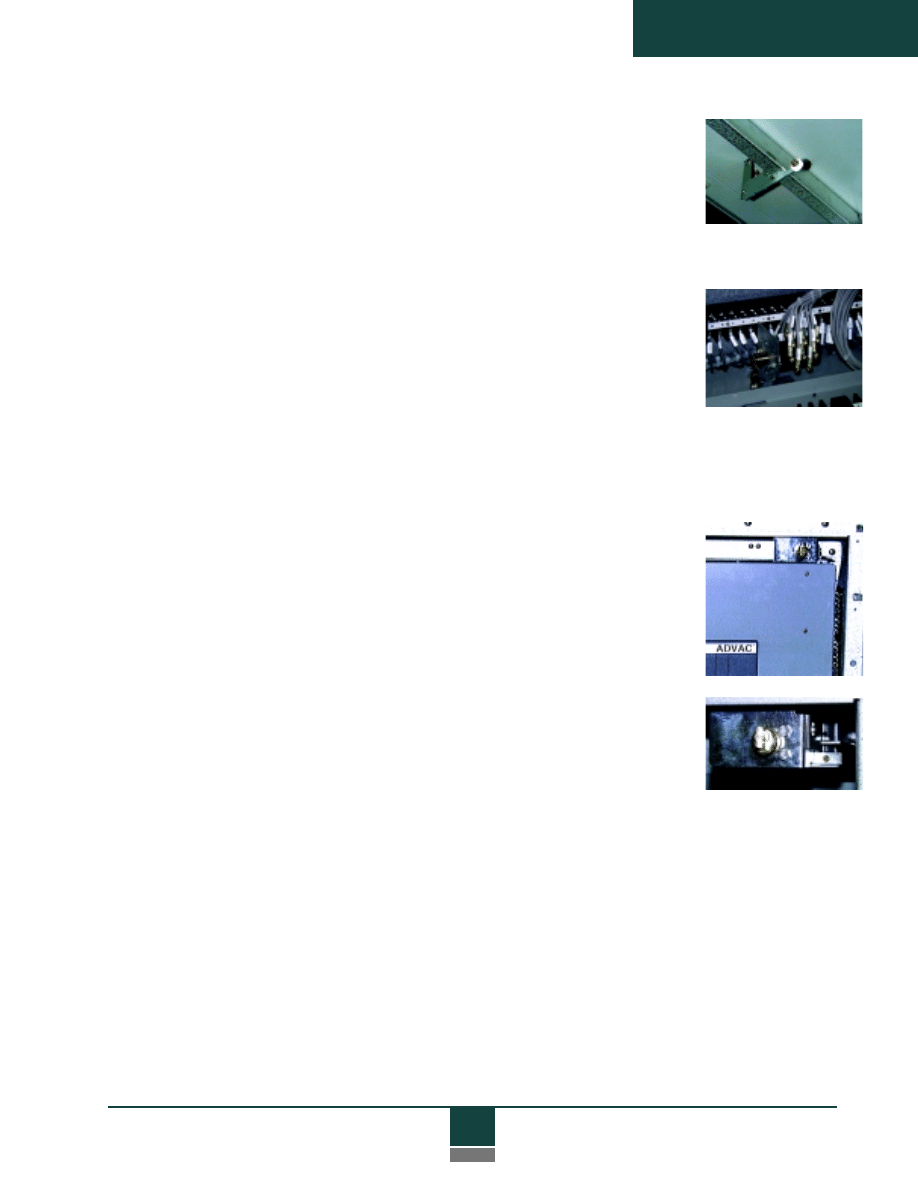
Dual Guide Rails
ADVAC breakers lock
securely into cells on
both sides. Dual guide
rails and self-aligning
primary and secondary
contacts assure smooth,
consistent racking, and
support the breaker
firmly during peak
short circuit conditions.
Current Transformers
Each primary compartment has room for up to four standard
accuracy current transformers (CTs) per phase.
Circuit Breaker Grounding
A stationary ground bar engages the
breaker grounding contact in the
Disconnected position and is
continuous between the Disconnected
and Connected positions.
Primary Supports
Primary contacts and CTs are
supported by standard glass-
polyester or optional
porcelain bushings.
Primary Shutters
Shutters automatically cover
primary contacts when the
breaker is not in the
Connected position.
Shutter closing is mechani-
cally forced by breaker
withdrawal, rather than
relying on springs or gravity.
Interference
Blocking
The compartment
has interfence blocking
to prevent insertion
of improperly rated
breakers.
13
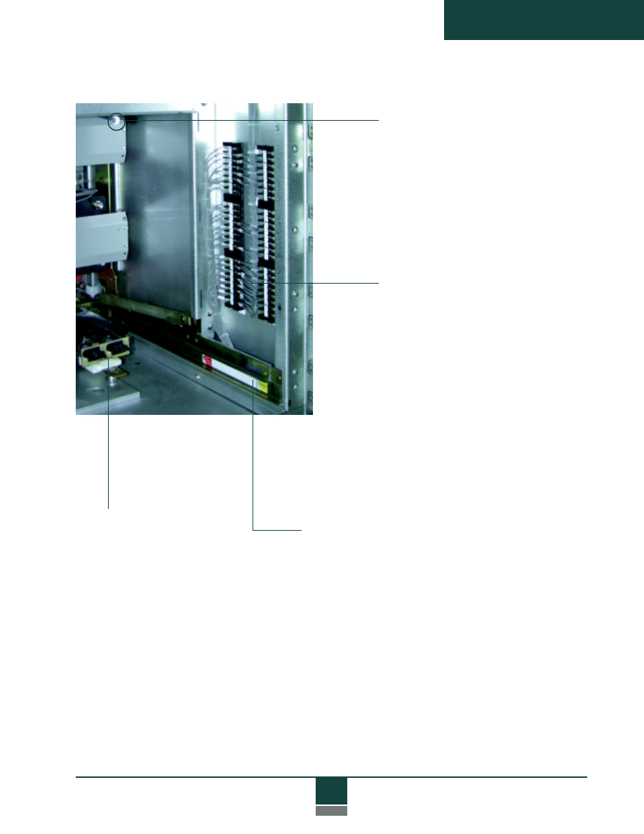
Product Description
Position Indicator
A position decal indicates breaker
position by alignment with the
front panel of the breaker.
TOC Actuator
Switch contacts are actuated
by the front panel as the
breaker moves in and out of
the Connected position.
Terminal Block
Mounting Space
Ample room is provided for
connections to secondary wiring
from circuit breakers, current
transformers and other devices.
Secondary Disconnect
A single 25-pin secondary
disconnect provides ample
connection capacity for
standard control circuits.
An optional dual disconnect
(shown) accommodates
optional control features.
Female contacts reside in
the cell so that potentially
energized control contacts
are recessed.

14
Product Description
Modular
Construction
Metal-clad switchgear systems with ADVAC circuit breakers are assembled
from a complete set of rugged, stackable circuit breaker and auxiliary
equipment modules. Primary modules are constructed from Galvalume
®
pre-coated steel for superior corrosion resistance. Hem-bending is used to
form a rigid, self-supporting structure. In addition to its outstanding
structural benefits, hem-bending results in rounded steel edges that greatly
reduce the risk of injury during shop handling and assembly, as well as
during field inspections and maintenance. Precision fabrication equipment
and advanced construction techniques result in high quality, properly aligned
modules that support efficient field installation and commissioning, and
provide consistent interchangeability of drawout assemblies with common
ratings. Modern bolted construction also greatly reduces the down time
and costs associated with system changes and expansions.
Module Types
A complete set of primary and low voltage modules are available.
All modules are 36 inches wide. Module dimensions shown below do not
include doors.
38"
39"
19"
39"
38"
39"
19"
22"
38"
22"
57"
22"
Primary Modules
Low Voltage Modules
Drawout
control power
transformers
and fuses
Drawout
potential
transformers
Circuit
Breakers

15
Product Description
Flexible
Arrangements
Superior value
ADVAC circuit breakers and metal-clad components offer a
variety of one-high and two-high switchgear configuration
options as shown below. Modules are stackable to a total
height of 95 inches.
In addition to the structural advantages of ABB modules, primary
compartments are shipped completely assembled and aligned in the factory.
Pre-installed equipment includes guide rails, primary bushings and contacts,
ground contact bar, and secondary disconnects pre-wired to terminal blocks.
For circuit breaker modules, the automatic primary shutters are also
installed, and the interference block is set for the cell current rating.
Modules also include predetermined routings for secondary wiring
in grounded steel channels. Ample room for terminal blocks is provided
on side panels. Grommeted “knock-outs” and convenient conduit
locations facilitate control wiring to upper and lower modules. In ABB
switchgear designs, all wiring to adjacent vertical sections is routed through
isolated low voltage modules.
TOC switches and Kirk
®
Key interlock mounting provisions are shipped as
kits for easy field installation.
1200 A - 2000 A
(2000 A in bottom only)
Any breaker rating
16
Product Description
Module
Assembly
Modules are enclosed by sheet steel on five sides, and are ready for
immediate assembly to adjacent units. Modules are designed to be
bolted together at frequent intervals using high quality hardware,
with
3/8
-inch bolts penetrating four layers of steel at each point.
Primary contact
Glass-polyester primary
contact support
Grommets for
control wiring
Ground bus connection
Each module has bolt provisions for connection to upper or lower
modules in the same vertical section, connection to modules in
adjacent vertical sections, and attachment of primary bus barriers and
rear cable compartments fabricated by the switchgear assembler.
Top, side and rear provisions
for bolting to adjacent modules
Circuit breaker module
(rear view)
17
Product Description
Doors
All modules have front flanges with hole patterns suitable for installing
bolted door hinges. Detailed information on recommended door con-
struction, ventilation, instrument mounting space, weight limits, and access
ports for breaker racking, are available for OEM reference.
Modern microprocessor technology enables
consolidation of multiple protective and
instrumentation functions for all phases into
fewer devices. Therefore, most relays and
controls can be mounted on isolated low
voltage compartment doors. In some cases,
the use of discrete relays or extensive protec-
tion systems dictate mounting instruments
on primary compartment doors. In these
situations, 10-inch front frame extensions
provide adequate depth for virtually all
door-mounted instruments. These frame
extensions match the flange hole pattern for easy bolting in place.
Extensions are available from ABB, or they can be fabricated by the
switchgear assembler using standard ABB frame extension drawings
for reference.
With appropriate low voltage compartments, the primary modules
generally stack to a total height of 95 inches in two-high breaker
configurations. Lower profile switchgear can be achieved for special
applications where a one-high breaker configuration is suitable.
18
Product Description
Circuit
Breaker
Modules
Operational features of the ADVAC circuit breaker modules are
described in “Cell Interface and Racking”.
Modules rated at 1200 amps are stackable as shown in the “Flexible
Arrangements” section, and upper and lower modules are similar.
Upper modules require top cover plates which are available from
ABB or readily fabricated by the switchgear assembler. Modules
rated at 2000 and 3000 amps have an elevated breaker racking
platform with a venting provision at the front of the cell. This
allows air to circulate under the breakers and eliminates the need for
vented doors.
All circuit breaker modules are suitable for top or bottom entry of
control wiring. Primary contacts are fabricated from solid copper.
In addition to a choice of 1200, 2000 or 3000 amp cells, important
options include the choice between standard glass-polyester
primary supports and optional porcelain bushings (standard on 3000
A cells), grounded metal or optional insulated polycarbonate
shutters, and single or dual secondary disconnects. Other cell-
mounted options include TOC switches (truck operated contacts)
and Kirk Key interlock mounting provisions.
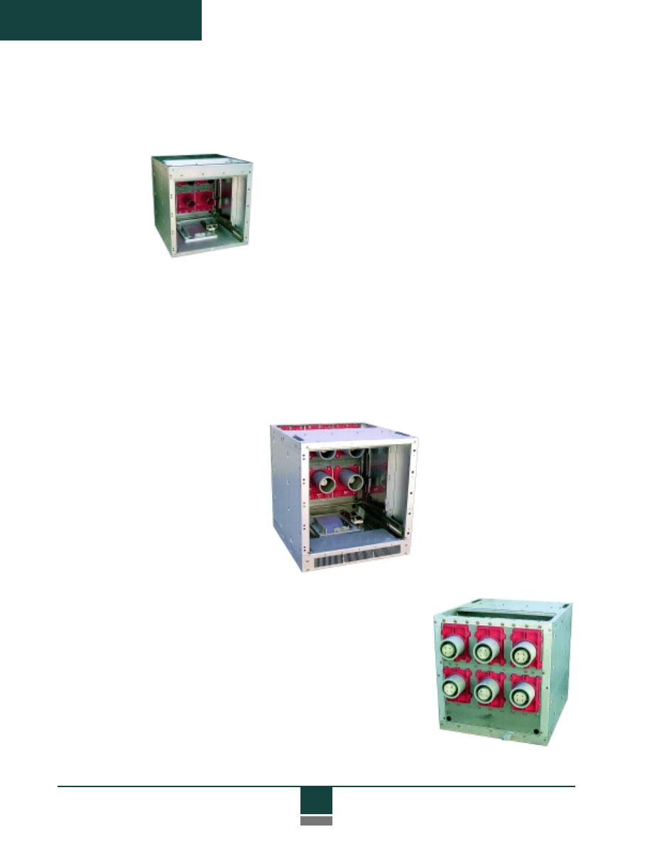
2000A Module with optional porce-
lain contact supports (shutters
removed)
Rear view of 3000A Module with
standard porcelain contact supports
19
Product Description
TOC Switches
Kirk Key
Interlocks
TOC switches indicate when the circuit
breaker is in the Connected position and
primary contacts are engaged. The TOC
switch consists of a mechanical switch
actuated by the ADVAC breaker panel on
insertion to the Connected position, and
a four-pole (2 “a”, 2 “b”), eight-pole (4
“a”, 4 “b”) or twelve-pole (6 “a”, 6 “b”)
electrical contact assembly driven by the
mechanical switch. The electrical
contacts and terminals are installed in an
isolated low voltage compartment
mounted over the breaker compartment.
Optional TOC switches are shipped as
kits for easy field installation.
Kirk interlocks are often used as safety
measures to prevent inserting a circuit
breaker unless a specified key is present,
assuring that equipment is operated in a
precise sequence. This feature is
typically used to mechanically prevent
access to circuits energized by a remote
source, or to prevent the simultaneous
connection of unsynchronized sources.
Optional Kirk Key interlock provisions
enable separate installation of single or
double Kirk interlocks. Kirk mounting
provisions are shipped as kits for field
installation. Kirk locks are not included
in mounting provision kits, and must be
ordered separately.
20
Product Description
Auxiliary Primary
Equipment
Potential
Transformer (PT)
Modules
PT modules accommodate industry-leading type VIY and VIZ
switchgear style potential transformers from ABB. Each module
accepts up to three transformers with line-to-line (L-L) or line-to-
ground (L-G) connections, and is supplied with the drawout truck,
PT mounting hardware, fuse clips and reusable fuse boots. PTs and
fuses are supplied by the switchgear assembler. The modules
include recessed primary “snuffer” arc-quenching contacts, dual
guide rails, and a racking system that uses the same accessories as
the circuit breaker modules. The snuffer contacts interrupt magne-
tizing currents and are recessed to prevent incidental contact with
energized circuits. Secondary contacts are automatically sequenced
and interlocked. PTs are automatically grounded on withdrawal to
discharge residual current.
Removable,
reuseable fuse
boots
Primary contacts
Compartment
locking tab
Integral wheels
Drawout truck and racking system
Secondary disconnect
PT drawout assembly with three transformers
21
Product Description
Fuse modules accommodate up to three primary fuses for use
with fixed-mount control power transformers and other primary
voltage level circuit protection. Fuse modules are supplied
with drawout trucks and equipped with primary contacts, fuse
mountings, and fuse clips for current limiting fuses.
Drawout Fuse
Modules
Racking
release
handles
Racking
access port
Auxiliary equipment drawer in Disconnected position
Control Power
Transformer
(CPT) Modules
CPT modules provide convenient mounting and operation of
single phase control power transformers in ratings to 15 kVA.
The modules include primary and secondary disconnects, dual guide
rails, and a racking system that uses the same accessories as circuit
breaker modules. Secondary contacts are sequenced and inter-
locked. ABB drawings indicate CPT manufacturer compatibility,
and drawout trucks with appropriate CPT and fuse mounting
hardware are included with the modules.
Note: ABB Auxiliary equipment modules do not include
transformers or fuses. These components are normally
supplied by the switchgear assembler.
22
Product Description
Low Voltage
Modules
The ABB design concept for metal-clad switchgear is to locate protection
and control devices in dedicated low voltage (LV) compartments. This
completely isolates and segregates control equipment and circuits from
high voltage areas, providing maximum safety for operations and mainte-
nance personnel working on switchgear controls.
Most control devices are mounted on LV module doors for easy readability
and convenient access. Devices that do not require immediate access, such
as auxiliary relays, transducers, and terminal blocks, are mounted inside the
LV compartments.
The LV compartments are available in 19- 38- and 57-inch height modules.
These modules feature the same rugged construction as primary modules,
and are supplied with grommets for cross-panel wiring, as well as cut-outs
for wiring to upper and lower primary modules in the same vertical section.
Provisions are also made for customer wiring entry.
ABB standard LV modules have a depth of 22 inches, and provide ample
room for control devices and wiring. The compartment depth is well-
suited for easy access for on-going inspections and maintenance. Low
voltage modules are available from ABB, or they can be fabricated by the
switchgear assembler using standard ABB compartment drawings for
reference.
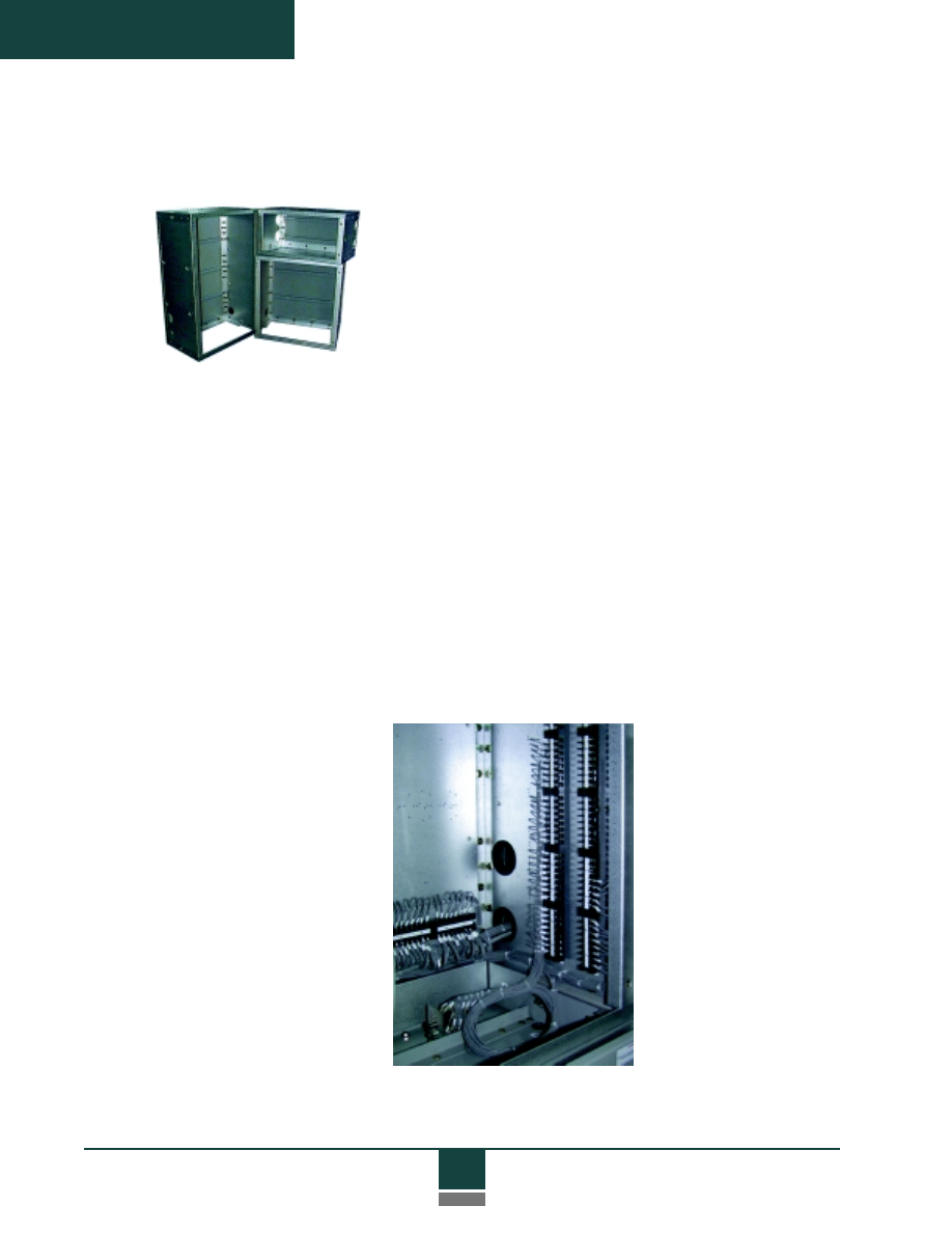
38-inch instrument compartment
with TOC switch and terminal
blocks for customer wiring and
interframe connections.
23
Product Description
Primary Bus
System
ADVAC circuit breaker modules and associated metal-clad compo-
nents are fully tested in complete switchgear in accordance with
rigorous ANSI requirements. The primary bus system used in the
certified design consists of a 100% copper main bus in 1200, 2000
and 3000 A ratings. The main bus is epoxy-insulated with an
advanced powder coat system. The bus is silver-plated at joints
and bolted together with a minimum of two
1/2
-inch SAE grade 5
bolts. Removeable, reusable boots are provided for each joint. The
main bus is not tapered and is easily extended at both ends.
The main bus and all jumps (connections from stationary primary
contacts to the horizontal bus) and risers (connections from station-
ary primary contacts to line or load terminations) are rigidly sup-
ported by insulating standoffs. Standard internal standoffs are Class
A20 glass-polyester. Standard interframe supports are also glass-
polyester. Porcelain insulator options are available.
Main bus sizes are identified in the Reference Section.
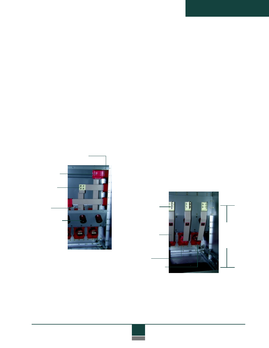
Glass-polyester
three-phase
interframe support
Reusable boot
Plated joint,
boot removed
Glass-polyester
riser supports
Jumps to
main bus
Cable lug
adapters
Riser bus
Reusable
boot
Plated joint,
boot removed
36"
minimum
space
for cable
terminations
Main Bus Compartment
(End section—cover removed)
Cable Compartment
(Main bus cover installed)
24
Product Description
Accessories
The ADVAC accessory group includes a complete array of
required and optional special tools for proper handling, operation
and maintenance of the circuit breakers and compartments.
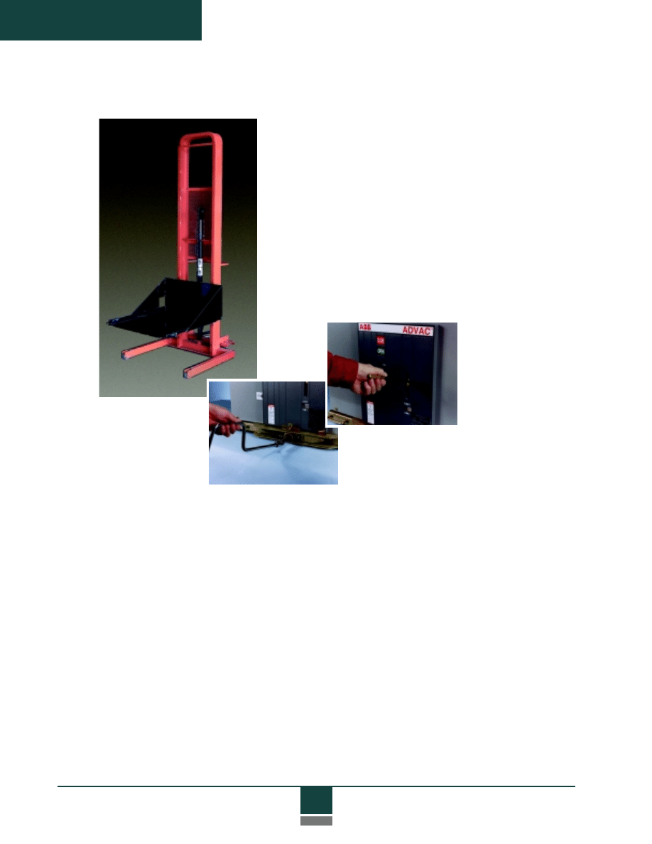
For maximum convenience, all withdrawable assemblies - circuit
breakers, PTs, CPTs, and fuses - use the same accessories.
Required accessories include a handle for manually charging
the circuit breaker operating mechanism, and a racking crank for
inserting and removing primary assemblies. A standard 16 mm socket
wrench with a swivel adapter can be conveniently used for racking.
A lift truck is also required for circuit breakers and other drawout
primary devices. The lift truck is a foot-operated hydraulic device
that docks with the switchgear, allowing a primary device to be
raised or lowered to the appropriate height and safely rolled into
the compartment. The lift truck has wheels for easy maneuvering
in restricted aisle space common to switchgear installations.
Primary devices are secured to the lift truck in the same manner
used for locking the devices into switchgear compartments. The lift
truck platform is lowered to a safe position before it is used as a
temporary transport device. All primary devices have self-contained
wheels for easy rolling on the floor and onto the lift truck.
25
Product Description
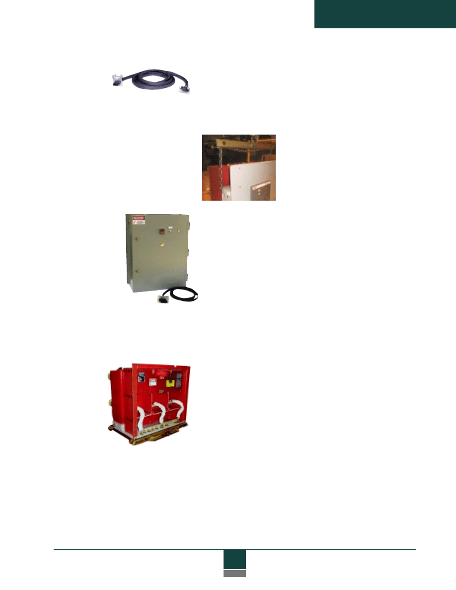
An optional lifting yoke is a simple
hook, chain and spreader bar assembly
used to lift circuit breakers with an
overhead crane or hoist.
A “G&T device” is a drawout assembly compatible with circuit
breaker compartments. The G&T provides a means to select
and test primary circuits in a controlled manner, and then to
connect deenergized primary circuits to the switchgear ground
bus to support maintenance activity. Refer to drawing on
page 52 in the Reference Section.
The racking system of the grounded G&T device can then be
padlocked or Kirk Key interlocked in the Connected position in
accordance with lock-out and tag-out safety procedures.
Ground and
Test Devices
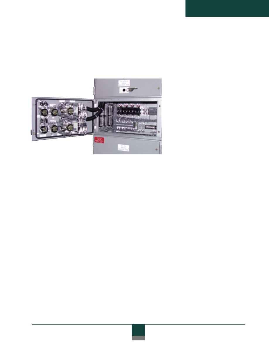
A “test cabinet” is a wall-mounted control cabinet connected to a
separate power source and containing switches to open and close a
breaker. The test cabinet has a female connector and an umbilical cord
(stored inside the cabinet) for connection to the breaker, and serves as an
aid to breaker inspection and maintenance in switchgear aisles or work areas.
A “test jumper” is an extension cord that allows the secondary
disconnect on a circuit breaker outside a breaker compartment
to be connected to the female connector inside the compartment.
This enables the breaker to be electrically operated using controls in
the switchgear, or electrically charged after manual operation of the
breaker in a switchgear aisle.

26
Product Description
A “Dummy Breaker” is a no-load disconnect device similar to a
drawout circuit breaker, but without an operating mechanism,
controls or interrupters. It provides a three-phase short circuit
current path between upper and lower terminals, and usually serves
to isolate entire switchgear line-ups or specific loads for mainte-
nance work. Dummy devices do not have load interrupting capabil-
ity, and must be Kirk Key interlocked with the switchgear power
source to prevent racking when primary circuits are energized.
Dummy
Circuit
Breakers
27
Technical Specifications
TECHNICAL
SPECIFICA
TIONS
Introduction ........................................................ 28
General Description ............................................ 29
Applicable Standards .......................................... 29
Ratings ................................................................ 30
Materials and Construction ................................ 30
Circuit Breaker Compartments .......................... 31
Auxiliary Compartments .................................... 32
Bus and Cable Compartments ............................ 33
Vacuum Circuit Breakers .................................... 34
Protection and Control ........................................ 37
Accessories .......................................................... 39
Documentation ................................................... 40
Testing and Verification ...................................... 40

28
Technical Specifications
Technical Specifications
Introduction
This section describes the basic design and functional requirements for
vacuum circuit breakers and indoor (NEMA 1) metal-clad switchgear
components. It is provided as a guide to assist in the specification of
switchgear, circuit breakers and related components to assure superior
safety, reliability and maintainability in the final switchgear product.
Features and provisions identified as optional should be selected as
appropriate for the application. This guide does not provide compre-
hensive recommendations for overall switchgear design, protective relay-
ing, coordination or instrumentation. This guide also does not address
requirements for outdoor applications.
Tables are located in the Reference Section.
This document is available in electronic format for word processing use from the
ABB web-site (http://www.abb.com/usa/t&d) or from an ABB OEM field
sales representative. For additional information, contact a sales representative or
the ABB North America Distribution Switchgear Group at 1-800-338-1585.
This specification covers the general requirements for medium
voltage metal-clad switchgear. Specific application requirements are
identified on project data sheets and single-line diagram(s). In general,
when resolving conflicting information, the following order of prece-
dence shall apply:
1. Single-line diagrams
2. Data sheets
3. This specification
4. Purchase order
5. Other referenced specifications
ADVAC - Advanced Design Vacuum Circuit Breakers

29
Technical Specifications
General
Description
The metal-clad switchgear shall be of free standing, self-supporting
modular construction in one-high and two-high arrangements. The
standard indoor frame size shall consist of 36-inch wide sections with
modules stacked to a height of 95 inches (maximum). A dress panel
shall be provided on each end of a lineup. The lineup may be extended
on either end (unless coupled to other equipment) by removal of the
end dress panels and the main bus covers.
The switchgear shall be provided with ABB ADVAC vacuum type
drawout circuit breakers or approved equal. The switchgear shall in-
clude circuit breaker and auxiliary compartments, drawout breakers and
auxiliary assemblies, the primary bus system, ground bus system, protec-
tion and control devices, and connection provisions for primary, ground
and control circuits, all functionally equivalent to project single-line
diagrams and data sheets except as noted.
Applicable
Standards
The switchgear and circuit breakers shall be designed, tested and manu-
factured in accordance with ANSI requirements for metal-clad
switchgear and the following applicable documents and industry stan-
dards:
ANSI/IEEE C37.04
Standard Rating Structure for AC HV Circuit
Breakers
C37.06
Preferred Ratings for AC HV Circuit Breakers
C37.09
Standard Test Procedure for AC HV Circuit
Breakers
C37.010
Application Guideline for AC HV Circuit
Breakers
C37.011
Application Guide for TRV for AC HV Circuit
Breakers
C37.012
Application Guide for Capacitance Switching
C37.11
Requirements for Electrical Control
C37.20.2 Standard for Metal-clad and Station-Type
Cubicle Switchgear
C37.55
Conformance Testing Procedure for Metal-clad
Switchgear
C57.13
Requirements for Instrument Transformers
NEC
National Electric Code, 1996 Edition
NEMA
CC-1
Electrical Power Connections
SG-4
Standards for Power Circuit Breakers
SG-5
Power Switchgear Assemblies for NEC/NFPA
250
Enclosures for Electrical Equipment

30
Technical Specifications
Ratings
The switchgear shall be rated at (4.76, 8.25, 15) kV maximum
continuous voltage, (250, 350, 500, 750, 1000) MVA nominal interrupting
capacity, and (1200, 2000, 3000) amps continuous current, as shown in
the “Rating Structure” table (page 40), with required and related capabili-
ties in accordance with referenced ANSI standards. Individual circuit
breaker continuous current ratings shall be as shown on the project
single-line diagram and data sheets.
Ratings are applicable to “General Purpose” circuit breakers as defined
by ANSI, except where specific “Definite Purpose” breakers and ratings
are noted in this specification or on project data sheets.
Switchgear will be designed for usual service conditions as defined in
ANSI C37.20.2, and de-rating factors for unusual service conditions shall
apply in accordance with this standard.
Materials and
Construction
Circuit breaker and auxiliary compartments shall be of modular con-
struction and fabricated primarily from 14-gauge pre-coated Galvalume
material (zinc-aluminum over cold-rolled carbon steel). Galvalume shall
not require painting due to superior corrosion resistance. Those compo-
nents, doors and panels which require welding, or which require greater
than 14-gauge material (and not accomplished by double walls of 14-
gauge material), shall be of carbon steel that has been phosphate treated
and painted with ANSI 61 (gray) baked-on corrosion resistant epoxy
enamel.
Hem-bends (rigid overlap bending) shall be consistently used to enhance
strength and to minimize potential exposures to sharp steel edges during
installation and maintenance.
Exterior doors and panels shall be securely hinged and fastened, and
shall be capable of handling the weight of door-mounted components
without deformation or sagging.
Door stops shall be provided to hold doors in the full open position.
Primary compartment doors shall be provided with windows of polycar-
bonate material to allow viewing of primary device position and indica-
tors mounted on the front of circuit breakers.
Provisions shall be made for the addition of Kirk Key Interlocks as
indicated on project single-line diagrams and data sheets.
Options:

31
Technical Specifications
Circuit Breaker
Compartments
C
ircuit breaker compartments shall be rated as shown on the project single-
line diagram and data sheets, and shall include support bushings with sta-
tionary primary contacts for engagement with circuit breakers or ground
and test (G&T) devices. Standard bushings shall be glass-reinforced polyes-
ter in 1200 A and 2000 A compartments, and porcelain bushings in 3000 A
compartments. The bushings shall be capable of supporting the weight of
specified current transformers. Primary contacts shall be made of copper
and designed to accept round, tulip-style connectors.
The 1200 A and 2000 A circuit breaker compartment bushings shall
be porcelain.
Low voltage, ring-core type current transformers (CTs) shall be
bushing-mounted, located behind the shutters and accessible from the front.
Bushing design shall accommodate up to four standard accuracy CTs per
phase for all ratings.
Solidly grounded metal shutters shall operate automatically by withdrawing
or inserting the circuit breaker or G&T device. The shutters shall block
access to primary contacts when the breaker is in the Test or Disconnected
positions or withdrawn from the compartment. Shutter grounding shall be
by dedicated ground wires, and shall not depend on grounding through
hinges or moving contact surfaces. Shutters shall be driven from both sides
simultaneously for smooth, balanced operation. Shutter closing shall be
automatically driven by the breaker, and shall not depend on gravity or
spring return systems. Shutters shall be lockable in the closed position
(padlocks supplied by others).
The shutters shall be made of non-metallic polycarbonate material.
A stationary ground contact shall be provided to interact with the ground
contact of the circuit breaker. The ground connection shall be made prior
to making of the primary or secondary contacts, and shall be continuous
from Disconnected through Connected positions. Additionally, circuit
breakers shall be grounded through the chassis and racking system in all
positions.
A single (25-pin) fully automatic self-aligning secondary disconnect shall be
provided as standard. The female portion of the disconnect system shall
reside in the breaker compartment, so that energized contacts are recessed
and remain “touch safe.”
A double (50-pin) disconnect arrangement shall be provided for compatibil-
ity with appropriately equipped circuit breakers, as shown on project
data sheets.
Option:
Option:
Option:

32
Technical Specifications
Auxiliary
Compartments
Circuit breaker compartments shall have interference blocking to prevent
the insertion of improperly rated devices. Breakers and G&T devices
rated at 2000 A shall be physically interchangeable in 1200 A compart-
ments for economy of spare devices. Note: Circuit breakers having dual
secondary disconnects are not interchangeable with devices using a single
secondary disconnect.
Refer to “Vacuum Circuit Breakers” for additional information on
circuit breakers.
Auxiliary compartments shall be provided where necessary for mounting
one or more of the following drawout auxiliary units, as shown on project
single-line diagrams and data sheets:
• Drawout potential transformers (PTs) with disconnecting
type primary current limiting fuses, with one or two drawers optional
in a vertical section with one circuit breaker or fuse/CPT compart-
ment. Each drawer shall contain up to 3 PTs,
connected L-L or L-G.
• Drawout control power transformers (CPTs) with disconnecting type
primary current limiting fuses, with one drawer optional in a vertical
section with one circuit breaker compartment, or up to two drawers
in a vertical section with no circuit breaker compartment. Each
drawer shall contain one CPT, up to 15 kVA single phase, connected
L-L or L-G. Secondary breakers shall be provided on ungrounded
secondary legs.
• Drawout current limiting fuses for stationary CPTs, with one drawer
optional in a vertical section with one circuit breaker compartment,
or up to two drawers in a vertical section with no circuit breaker
compartment. Each drawer shall contain up to three fuses connected
L-L or L-G.
Drawout CPTs and fuse units for stationary CPTs shall be provided with
an interlock to a switch or secondary circuit breaker to prevent withdrawal
of an energized unit.
Drawout units shall use the same racking system as the circuit breakers for
open or closed door racking (except that no Test position applies), and
shall use the same accessories as the circuit breakers. Primary connections
shall be made by tapered, self-aligning silver-plated copper contacts
mounted on glass polyester bushings and connected to primary circuits by
rigid conductors or properly braced cables. The primary contacts shall be
of a recessed arc-quenching design that interrupts magnetizing current
and prevents incidental contact with energized circuits.

33
Technical Specifications
Secondary PT and CPT connections shall also be self-aligning copper
contacts. Primary and secondary connections shall be fully automatic
during insertion and withdrawal of the auxiliary unit.
Porcelain bushings shall be supplied as supports for stationary
primary contacts in auxiliary compartments.
Drawout auxiliary trucks shall be grounded at all times. Transformer
windings or primary fuses shall be grounded when withdrawn to dis-
charge residual current.
Option:
Bus and Cable
Compartments
The primary bus system shall be made of 100% copper with full round
edges, and shall have self-cooled ratings as specified on the project
single-line diagram or data sheets. Bus bar connections shall be silver-
plated and mechanically secured with reusable hardware that will main-
tain adequate pressures with the operating temperature range of the
switchgear.
Conductors shall be epoxy insulated, except at bolted joints. Joints shall
be covered with removable, reusable boots to facilitate field inspection
and maintenance.
The main (horizontal) bus compartment shall be separated from the
other compartments by an 11-gauge steel barrier (or equivalent) and shall
fully enclose the main bus. The main bus compartment shall be acces-
sible from the rear through the cable compartment. Main bus ratings
shall match the highest rated circuit breaker continuous current ratings
(unless a higher rating is specified on the project single-line diagram or
data sheets) and shall comply with ANSI temperature rise requirements.
The main bus shall not be tapered.
Bus supports and insulation materials shall be flame-retardant, track
resistant, and non-hygroscopic. Supports for 1200 A and 2000 A units
shall be glass-reinforced polyester. Supports for 3000 A bus shall be
porcelain.
Bus supports for 1200 A and 2000 A shall be porcelain.
A termination bus shall be provided from the circuit breaker primary
disconnects to a location to allow cable connections to other equipment.
Bus connections to cables and bus duct shall be rigid. Termination bus
arrangements shall allow at least 36 inches for primary cable terminations
and stress cones. Connections to roof entrance bushings shall be of the
flexible type. Standard termination bus shall meet the bolt hole require-
ments of NEMA CC-1-4.05, and will typically be the NEMA four-hole
pattern.
Option:
Option:

34
Technical Specifications
Crimp or compression type cable lugs will be provided for each switchgear
section as shown on project data sheets.
The design shall be adaptable for top or bottom primary entrance arrangements.
In two-high arrangements, each set of primary connections and zero-sequence
current transformers, if applicable, shall be isolated into separate compartments
by a grounded steel partition in accordance with ANSI standards. Easily remov-
able primary and secondary cable entry plates of carbon steel shall be provided.
Cable entry plates shall be of non-magnetic material.
The cable compartment shall have mounting provisions for surge arresters,
ground sensors and cable supports as shown on project data sheets.
A
1/4
x 2 inch solid copper ground bus, to which the entire metallic enclosure is
solidly connected, shall extend through the length of the switchgear. The ground
bus shall be accessible in the cable compartment, and shall have connection
provisions for each switchgear section.
Vacuum Circuit
Breakers
General
The circuit breaker shall be an ABB ADVAC or approved equal three-
pole drawout type breaker, electrically operated, with manual or electric
motor charging of a spring type stored energy operating mechanism. The
breaker is intended for use as a General Purpose device in accordance
with applicable ANSI standards.
Definite purpose or non-standard ratings are required in accordance with
project data sheets, and availability is confirmed in writing with the
vendor.
Circuit breakers of the same type, rating and control features shall be
electrically and mechanically interchangeable.
Racking System
and Interlocks
The circuit breaker shall be inserted and withdrawn by means of a rack-
ing system, which can be operated with the compartment door open or
closed. The racking system shall provide smooth, consistent racking, and
shall secure the breaker from both sides of the cell in all racking posi-
tions. During racking, the breaker shall automatically open and close cell-
mounted safety shutters to cover stationary primary contacts when the
breaker is not in the Connected position.
Option:
Option:
Options:

35
Technical Specifications
Controls
Opening and closing speed shall be independent of the operator
or of control voltage within the rated control voltage range. Circuit
breaker charge, close and trip circuits shall be electrically separate, and
control voltages for each circuit shall be independently selectable from
the full range of ANSI preferred control voltages. Manual provisions
shall be provided for closing, tripping and charging the breaker. These
provisions shall be installed and easily accessible at the front of the
breaker.
A self-aligning, fully automatic secondary coupling system shall
be used to connect and disconnect all control wiring during circuit
breaker insertion and withdrawal. The secondary disconnect shall require
no manual intervention to attain proper position when the breaker is
racked to the Connected, Test or Disconnected positions. Secondary
contacts shall use a tin-lead contact finish.
The breaker shall include eight on-board auxiliary contacts (4 “a”, 4 “b”)
for customer use, wired through the secondary disconnect. All breaker-
mounted contacts shall operate in both Connected and
Test positions.
Nine additional contacts (5 “a”, 4 “b”) shall be installed on the
breaker and wired through the secondary disconnect, for a total
of 17 on-board contacts.
The racking system shall have three distinct positions, in addition
to the withdrawn position (free movement): Disconnected (both primary
and secondary contacts disengaged), Test (primary contacts disconnected
and shutter closed, but control contacts engaged), and Connected (pri-
mary and secondary contacts engaged). Positive stops shall be provided
for all three positions, with deliberate operator intervention required to
enable continued insertion or withdrawal of the breaker from any posi-
tion.
The racking system and all moving parts of the breaker-cell interface,
including the secondary coupler, shutter actuator and ground contact,
shall be capable of 250 complete rack-in/rack-out operations without
maintenance.
It shall not be possible to insert or withdraw a closed breaker, and the
breaker shall not be allowed to close within a cell unless it is in a positive
Connected, Test, or Disconnected position. The springs in the stored-
energy operating mechanism shall be automatically discharged prior to
removing a circuit breaker from a compartment. (other than spring pre-
load charges which do not have the capacity to operate the circuit
breaker).
Option:

36
Technical Specifications
The breaker shall have flags to indicate open or closed position, and
spring charge status. Only the correct status flag for any single function
shall be visible. Pointer systems shall not be used to indicate status.
Additionally, the breaker shall have a five-digit, non-resetting operation
counter clearly visible from the front of the breaker. The operation
counter shall advance when the breaker opens.
A solid state control device shall be used to assure proper sequencing of
anti-pump circuits. Mechanical relays shall not be used.
All control devices shall be universal AC/DC, or DC supplied through
rectifiers, for AC or DC application flexibility with standard parts. All
control components shall be front-accessible for inspections and easily
removable for maintenance.
Dual isolated direct-acting shunt trip coils shall be supplied for breakers
as noted on data sheets, and wired through separate secondary control
sources for complete redundancy.
A direct-acting undervoltage trip shall be supplied for breakers as noted
on data sheets. The undervoltage trip shall operate when the control
voltage drops to a predetermined value below the nominal control
voltage.
Current Path
Each primary lead assembly shall consist of a vacuum interrupter housed
in a glass-polyester support, with copper upper and lower leads, and shall
use tulip-type self-aligning primary disconnects. Current transfer to
moving interrupter stems shall be via flexible connectors or brush con-
tacts with no moving parts. Primary disconnects and contact surfaces of
other current carrying parts shall be silver-plated.
A dedicated ground contact shall be provided to engage the stationary
ground contact in the circuit breaker compartment to ground the circuit
breaker in all positions from Disconnected through Connected.
Maintenance
and Handling
The operating mechanism shall be front-accessible, and all routine main-
tenance shall be performed with the breaker in an upright position.
Interrupters shall have a contact wear indicator or other simple contact
measurement that requires no special tools. Circuit breakers shall have
self-contained wheels designed for easy insertion, removal and transport
on flat indoor surfaces.
Options:

37
Technical Specifications
Protection
and Control
Relays and
Instruments
Relays and instruments shall be provided and wired as specified on the
project single-line diagram and data sheets. Multi-function, three-phase
microprocessor-based relay and control devices shall be used to the
maximum practical extent. For maximum safety and ease of mainte-
nance, the use of larger low voltage compartments and one-high con-
struction shall be given precedence over stacked primary compartments
when alternative relay and instrument types are used. Door-mounted
protective relays shall be drawout type whenever practical.
Electromechanical meters, when used, shall be the flush-mount 1%
accuracy taut-band switchboard type, with a minimum 250% scale.
Current
Transformers
ABB type SAB current transformers shall be supplied as shown on
project data sheets and the single-line diagram. Zero sequence transform-
ers shall be ABB type BYZ-S. Ratings and accuracy class shall be in
accordance with ANSI C57.13. CT nameplates shall be located on the
CT housing and information provided shall be in accordance with ANSI
C57.13. CT windings shall terminate on screw type terminals on the CT
housings and shall be wired to shorting terminal blocks.
ABB type VIY and VIZ potential transformers shall be supplied in
accordance with project data sheets and the single-line diagram. Poten-
tial transformer ratings and accuracy class shall be in accordance with
ANSI C57.13 and designed to withstand the Basic Impulse Level (BIL)
of the switchgear. Potential transformers shall always be fused. Potential
transformers shall be mounted as draw-out devices in auxiliary compart-
ments.
Potential
Transformers
Circuit breaker auxiliary contacts shall be used instead of cell-mounted
mechanism operated contacts (MOC switches) for each breaker so noted
on project data sheets. The auxiliary contacts shall be wired through the
automatic secondary disconnect system. Refer to “Vacuum Circuit
Breakers” for additional requirements.
A four contact (2 “a”, 2 “b”), eight-contact (4 “a”, 4 “b”) or twelve-
contact (6 “a”, 6 “b”) truck operated contact (TOC) actuator and switch
assembly shall be provided to indicate when the breaker is in the fully
Connected position, for each breaker so noted on project data sheets.
Spare contacts shall be wired to terminal blocks for easy access and
future use.
Auxiliary
Switches
Option:

38
Technical Specifications
Control Switches
Breaker control switches shall use pistol-grip handles and will not
be mounted adjacent to meter switches. Meter switches shall use
knurled-type round handles. Control and instrument switches shall be
provided and wired in accordance with specified single-line diagrams
and data
sheets, and shall be mounted only on low voltage compartment
doors and panels.
The switchgear shall use 14 AWG type SIS stranded extra-flexible, 600
volt flame retardant and UL-listed switchboard wire. Larger wire sizes up
to #8 may be used as necessary for CT circuits. Control bus, where
provided, shall be #8 AWG minimum, depending on required ampacity.
Terminal blocks for customer connections shall be provided in the low
voltage compartment. Internal wiring shall be connected to only one side
of these terminal blocks, with a maximum of two wires per terminal, and
terminals shall be clearly marked.
Control wiring shall be enclosed in a grounded metal wireway when
routed through a high voltage compartment. Splices are not permitted,
except at terminal blocks. Wiring shall be neatly bundled and tied or
secured in plastic wireways on doors and in low voltage compartments,
and shall be protected from rubbing against door flanges or other parts
of the enclosure.
Control circuits shall incorporate all necessary switching and protective
devices, such as fuses or molded case circuit breakers, as specified on
project data sheets. Charge, close and trip circuits shall be separately
fused. Dead-front pull-fuse blocks shall be used for circuit protection
and disconnect. Vendor’s recommended fuse sizes for each control
voltage shall be used. Ends shall terminate with ring-tongue terminals
on screw-type terminal blocks, unless prohibited by the design of con-
nection ponts on control devices. Terminal block screws shall use vibra-
tion-resistant hardware. Interframe connections shall be made only at
low voltage compartments.
Sleeve-type wire markers shall be provided at both ends of each wire.
Ring-tongue terminals shall be insulated.
Control Wiring
Options:

39
Technical Specifications
Space heaters shall be provided at appropriate locations in each vertical
section. Heaters shall be protected to prevent accidental contact by
operating personnel.
Space heaters shall be separately fused for each vertical section or
breaker, as applicable. Space heaters shall be energized whenever circuit
breakers are open or controlled by an automatic thermostat located in
each vertical section or lineup, as shown on project data sheets. Optional
heater controls shall include disconnect switches, bypass switches, amme-
ters and thermostats.
Note: Space heaters shall be standard on outdoor equipment.
Space Heaters
The following accessories shall be provided for each lineup or in quanti-
ties as noted on project data sheets:
• Hand crank (16 mm socket drive) for manually operating
racking system for the circuit breaker, PT, CPT, or draw-out
fuse (required)
• Handle for manually charging the stored energy system on circuit
breakers (required)
• Transport and lifting device to allow a circuit breaker, or
auxiliary drawout unit, to be elevated and then inserted or withdrawn
from upper or lower compartments (required)
• Electrical test jumper for connecting the breaker to the switchgear
control circuit while the breaker is completely out
of the cell
• Electrical test cabinet with door-mounted open and close
pushbuttons for testing the circuit breaker away from the switchgear
• Ground & Test device – three-terminal or six-terminal, manually
operated standard device
• Lifting yoke or similar breaker accessory for overhead lifting of
circuit breakers
Accessories
Options:
Options:

40
Technical Specifications
Design tests, to verify ANSI ratings as identified in this specification,
shall be documented as required by ISO 9001 and available for review
and inspection.
Testing and
Verification
Standard approval drawings shall consist of a system single-line drawing;
general arrangement; front view; floor plan; nameplate drawing; and bill
of materials. Final drawings shall consist of as-built approval drawings
plus three-phase elementary, schematic, and interconnection wiring
diagrams.
Drawings shall indicate all equipment, but only such equipment,
as is actually in the switchgear scope of supply. All user connection and
interface points shall be clearly marked, including primary and secondary
cable entrances and connection points; installation details; and inter-
frame assembly and connection details for shipping splits.
Drawings shall be professionally prepared on computer aided drafting
systems to the maximum extent practical, and shall be provided to the
customer by electromagnetic disk or on reproducible and paper copies in
quantities as shown on project data sheets.
An instruction manual shall be provided with necessary information for
receiving, handling, storage, installation, operation and maintenance. The
instruction manual shall assist in identification and ordering of recom-
mended spare parts.
Documentation

Reference
41
REFERENCE
Rating Structure .............................................. 4 2
Capacitance Switching Ratings .................... 4 3
Altitude Rating Correction Factors ............. 4 3
Mechanical Endurance .................................. 4 4
Noise Level ........................................................ 4 4
Auxiliary and TOC Switches ........................ 4 5
Close and Trip Coils ....................................... 4 6
Charging Motor ............................................... 4 7
Timing Characteristics .................................. 4 8
Vacuum Inter r upters ..................................... 4 8
Bus Support Materials ................................... 4 9
Main Bus Sizes ................................................. 4 9
Circuit Breaker Schematic Diagram ........... 5 0
Circuit Breaker Outline ................................. 5 1
Ground and Test Device Outline ................... 5 2

42
Reference
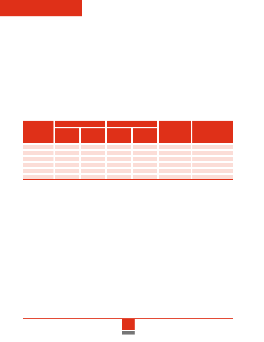
Rating
Structure
The following table identifies standard ADVAC circuit breaker
types and ratings, and provides the most commonly required
ratings and related capabilities for metal-clad switchgear.
ADVAC circuit breakers are suitable for “General Purpose”
applications as defined by applicable ANSI standards (refer to
Technical Specification). Contact the factory for availability of
non-standard or “Definite Purpose” ratings.
Reference
ADVAC - Advanced Design Vacuum Circuit Breakers
Rated
Rated Short
Capability
Voltage
Impulse
Circuit Current
Nominal
kV
Low Freq.
Level
kA Sym
Short
Close
Rated
Voltage
Nominal
Withstand
(BIL)
Time
and
Voltage
Breaker
Class
MVA
Min.
Max.
Voltage
kV
@ Min.
@ Max.
kA rms
Latch
Range
Type
kV
Class
rms
rms
kV rms
Crest
kV
kV
2 Sec.
kA
Peak
Factor
5ADV36
4.16
250
3.8
4.76
19
60
36
29
36
97
1.24
5ADV49
4.16
350
4
4.76
19
60
49
41
49
132
1.19
7.5ADV41
7.2
500
6.6
8.25
36
95
41
33
41
111
1.25
15ADV23
13.8
500
11.5
15
36
95
23
18
23
62
1.3
15ADV36
13.8
750
11.5
15
36
95
36
28
36
97
1.3
15ADV48
13.8
1000
11.5
15
36
95
48
37
48
130
1.3
NOTES:
1. Each circuit breaker is available in continuous current ratings of 1200, 2000 or 3000 A rms.
2. Interrupting time is rated at 5 cycles (0 — 100%).
3. The asymmetric capability ratio rating is 1.2.
4. Ratings are 50/60 Hz basis.

Reference
43
Capacitance
Switching
Ratings
Capacitance switching ratings are as specified in the table below
and are subject to the following conditions.
1. The transient voltage from line-to-ground shall not exceed
three times the maximum design line to ground crest
voltage as measured at the circuit breaker terminals.
2. The number of re-strikes or re-ignitions shall not be limited
as long as the transient voltage to ground does not exceed
the value given in number 1 above.
3. The capacitor rating applies only to “Single Bank
Switching”.
Interrupting time is in accordance with the rated interrupting time
of the circuit breaker.
Altitude
Rating
Correction
Factors
ADVAC Breaker Continuous Current Rating
1200 A
2000 A
Rated Maximum
Rated Short Circuit
General
Definite
General
Definite
Voltage (kV RMS)
Current (kA RMS)
Purpose
Purpose
Purpose
Purpose
0
4.76
29
400
630
400
1000
0
4.76
41
400
630
400
0
630
0
8.25
33
250
630
250
1000
15.0
0
18
250
630
250
1000
15.0
0
28
250
630
250
1000
15.0
0
37
250
630
250
0
630
Contact factory for availability of capacitance switching information on 3000 A circuit breakers.
Rating Correction Factor*
Continuous
Voltage & Dielectric
Altitude (ft.)
Current
Withstand
0
3,300 (and below)
1.00
1.00
0
5,000
0.99
0.95
10,000
0.95
0.80
*Values for intermediate altitudes may be derived from linear interpolation.
This table must be used in accordance with ANSI C37.04 to
correct published circuit breaker ratings for operation at altitudes
over 3,300 feet above sea level.

44
Reference
Mechanical
Endurance
ADVAC circuit breakers are subjected to extensive testing for
durability in accordance with ANSI standards. This information
is provided as a guide to maintenance planning under normal
operating conditions. Actual experience may vary based on
operational conditions and maintenance practices. Tested
values of accumulated interrupting duty (KSI) do not constitute
warranted performance.
Noise Level
5ADV36
15ADV23
7.5ADV41
(see 15ADV36 for
5ADV49
Breaker Types
15ADV36
2000 A rating)
15ADV48
All
Continuous Current
1200-2000 A
1200 A
1200 - 2000 A
3000 A
No-load mechanical
10,000
%
10,000
%
5,000
%
5,000
%
Between servicing
2,000
%
2,000
%
1,000
%
1,000
%
Full load current
1,000
%
1,000
%
500
%
500
%
Rated KSI
800%
800%
800%
800%
Tested KSI
2300%
1425%
815%
815%
Open, peak (dBA) at 3 ft
< 105
Close, peak (dBA) at 3 ft
< 105
Noise level measurements of circuit breaker operations with
compartment door open or circuit breaker withdrawn from cell.

Reference
45
Circuit breaker auxiliary switches operate whenever the breaker
opens or closes. Contacts are compression type, mounted on
the breaker and wired to switchgear terminal blocks through the
secondary disconnect system. Contacts are operated through
simple mechanical links from an auxiliary drive shaft which rotates
in conjunction with the main drive shaft. Switch contacts are silver-
plated.
The standard contact configuration is four “a” contacts (normally
open when the breaker is open), and four “b” contacts (normally
closed when the breaker is open). An optional dual secondary
disconnect enables the addition of five “a” contacts and four “b”
contacts, for a total of nine “a” and eight “b” contacts. The contacts
are not field reversible.
Auxiliary
and TOC
Switches
Auxiliary Contact
Continuous
Switching
Current Ratings
(A)
(A)
@ 250 VDC
10
0
2.0
@ 125 VDC
10
0
4.0
@ 48 VDC
10
0
6.0
@ 24 VDC
10
0
7.7
@ 240 VAC
10
10.0
@ 120 VAC
10
10.0
Optional TOC switches are actuated by
movement of the ADVAC front panel to
indicate when the breaker is in the
Connected position. TOC switch contacts
are mounted in an isolated low voltage
area at the top of the breaker compart-
ment. TOC switches are available with
four, eight or twelve contacts, with an
even number of “a” contacts (normally
open when breaker is not Connected) and
“b” contacts (normally closed with breaker
is not Connected). Contacts are not
field-reversible.
TOC Switch
Continuous
Switching
Current Ratings
(A)
(A)
@ 250 VDC
20
0
5.0
@ 125 VDC
20
10.0
@ 48 VDC
20
12.0
@ 24 VDC
20
15.0
@ 240 VAC
20
10.0
@ 120 VAC
20
15.0
Auxiliary contacts operate whenever the
breaker is operated, regardless of breaker
position in the compartment. If control
circuits require differentiation between
connected and disconnected positions, it is
necessary to wire an optional truck
operated contact (TOC) into the
appropriate auxiliary switch circuit(s).
46
Reference
Close and
Trip Coils
Circuit breaker close and trip coils are reliable solenoids
with rotary movement that actuate appropriate operating
mechanism linkages.
All coils operate from DC voltages supplied by a solid state
control device (SSCD). The SSCD contains rectifiers that adapt
the coils to AC or DC supply voltages, and uses solid state
components to replace conventional anti-pump closing circuits.
Conventional wire-wound resistors for AC controls are also
eliminated. The SSCD module uses a highly reliable locking
connector, and is easily replaceable for convenient control
voltage changes.
Note that the minimum value for the 24 VDC trip coil is
higher (more restrictive) than the normal range defined by
ANSI standards.
24 and 48 VDC control functions are not recommended unless
near the battery source, or unless special effort is made to ensure
adequacy of conductors.
AC trip voltages are not recommended under any conditions,
due to the reliability of AC power sources. If the only available
control power source is AC, the recommended procedure is to
use a capacitor trip device for each trip circuit.
ADVAC circuit breakers are available with a second trip coil.
This option uses the standard trip coil, except that a different
control voltage may be selected. A dual secondary disconnect
must be used whenever a second shunt trip is specified. This
provides complete redundancy of the trip circuit, from the trip
coil through the secondary disconnect system to the switchgear
terminal blocks.
Trip Coil
Close Coil
Rated
Nominal
Rated
Nominal
Impedance
Recommended
Nominal Coil
voltage
Current
voltage
Current
+/- 5%
Class RK-5
Voltage (V)
range (V)
(A)
range (V)
(A)
(Ohms)
Fuse Size (A)
0
24 VDC
20-28
9.6
—
—
*
15
0
48 VDC
28-56
4.8
38-56
4.8
0
47
15
125 VDC
0
70-140
3.0
100-140
3.0
198
15
250 VDC
140-280
1.5
200-280
1.5
00
8
15
120 VAC
104-127
3.0
104-127
3.0
198
15
240 VAC
208-254
1.5
208-254
1.5
00
8
15
*Contact factory for impedance value

Reference
47
ADVAC circuit breakers are also available with an optional
undervoltage trip feature. This is a direct acting trip coil that
actuates the trip linkage when the control voltage drops below
35 - 70% of the nominal range. This prevents a condition from
happening in which control voltage is no longer available to trip a
breaker. This feature is not available for 24 VDC trip circuits.
Charging
Motor
ADVAC circuit breakers use a reliable and durable motor for
electrically charging the toroidal spring in the stored energy
operating mechanism. The two-pole universal motor is suitable
for AC or DC voltages at each nominal rating. The motor is rated
at 0.35 horsepower, and uses a 100:1 internal gear reduction.
Advantages of this motor include a ventilated, lightweight
aluminum housing; permanent internal lubrication; and a
continuous duty rating.
Electric charging requires 7-8 seconds at nominal control voltage.
The 48 VDC motor voltage is not recommended unless located
near a battery or special effort is made to assure adequacy of
conductors.
Manual charging is also quick and convenient, requiring
approximately 25 easy strokes of a manual charging handle
inserted at the front panel of the circuit breaker. The manual
procedure takes about 25 seconds to complete.
Nominal
Nominal
Stalled
No Load
Charging
Recommended
Charge
voltage
Current
Inrush
Current
Current
Time
Class RK-5
Motor
range (V)
(A)
Current
(A)
(A)
(Nominal)
Fuse Size (A)
0
48 VDC
38-56
8
25.0
3.5
125 VDC
100-140
4
12.5
1.5
250 VDC
200-280
2
6-8x
0
6.5
0.8
7-8 seconds
15
120 VAC
104-127
4
12.5
1.5
240 VAC
208-254
2
0
6.5
0.8

48
Reference
Timing
Characteristics
The ADVAC circuit breaker uses the same stored energy
mechanism for all ratings, resulting in consistent operation
and timing characteristics in all ratings and configurations.
Vacuum
Interrupters
Nominal closing time
60 ms
Nominal opening time
35-40 ms
Arcing time
< 15 ms
Nominal interrupting time
< 55 ms
Motor charging time
7-8 seconds *
Manual charging time
~ 25 seconds **
*
*at nominal control voltage
**requires approximately 25 strokes of charging handle
ADVAC circuit breakers use superior quality vacuum interrupters
with proven reliability over a long life. All interrupters use
advanced copper-chrome contact material for superior
performance and minimum current chop.
***** Overvoltages are dependent on the surge impedance of the circuit
5ADV36
15ADV23
7.5ADV41
(see 15ADV36 for
5ADV49
Breaker Types
15ADV36
2000 A rating)
15ADV48
All
Continuous Current
1200-2000 A
1200 A
1200 - 2000 A
3000 A
Contact shape
Spiral
Contact resistance (
@ rated current)
<
10
µΩ
<
18
µΩ
<
10
µΩ
<
10
µΩ
Field design
Radial
No-load mechanical life
10,000 operations
5,000 operations
Vacuum (Torr)
10
-8
to 10
-7
Maximum chop current*
~5 A
Moving stem current
Flexible
Flexible
Brush
Brush
transfer method

Reference
49
Bus Support
Materials
ADVAC design certifications are based on glass-polyester and
porcelain primary bus supports. Glass-polyester is standard for
primary contacts and bus rated at 1200 A and 2000 A, and
porcelain is standard at the 3000 A rating. Porcelain supports are
also available at 1200 A and 2000 A. Separate drawings are
available to indicate the position and dimensions of the
compartment-mounted primary contact supports, inter-frame
horizontal bus supports, and Class A-20 standoff insulators.
Physical characteristics of glass-polyester and porcelain are
provided in the following table.
Glass
Characteristic
Polyester
Porcelain
Flexural Strength, psi
15 - 27,000
10,500
Tensile Strength, psi
14,000
0
6,000
Izod Impact ft-lb. per inch of notch
0
6 - 12
1.5
Thermal Shock cycles 32° - 2300°F
100+
1
Dielectric Strength (Short Time)
vpm .125" thick, 25°C
350 - 375
300
Dielectric Constant
4 - 6
6
Main Bus
Sizes
ADVAC design certifications are based on 100% copper bus with
full round edges and sizes as shown in the following table. The
main horizontal bus is not tapered. Connection joints are silver-
plated, and at least two properly-torqued
1/2
-inch SAE grade 5
steel bolts are used at each joint. The bus is epoxy insulated, and
removable boots are used at joints.
Main Bus Sizes
Rating
Quantity
Size
0
5 kV, 250 MVA
1200 A
15 kV, 500 MVA
1
.25" x 4"
15 kV, 750 MVA
0
5 kV, 350 MVA
1200 A
7.5 kV, 500 MVA
1
.75" x 4"
15 kV, 1000 MVA
2000 A
All
1
.75" x 4"
3000 A
All
2
.75" x 4"
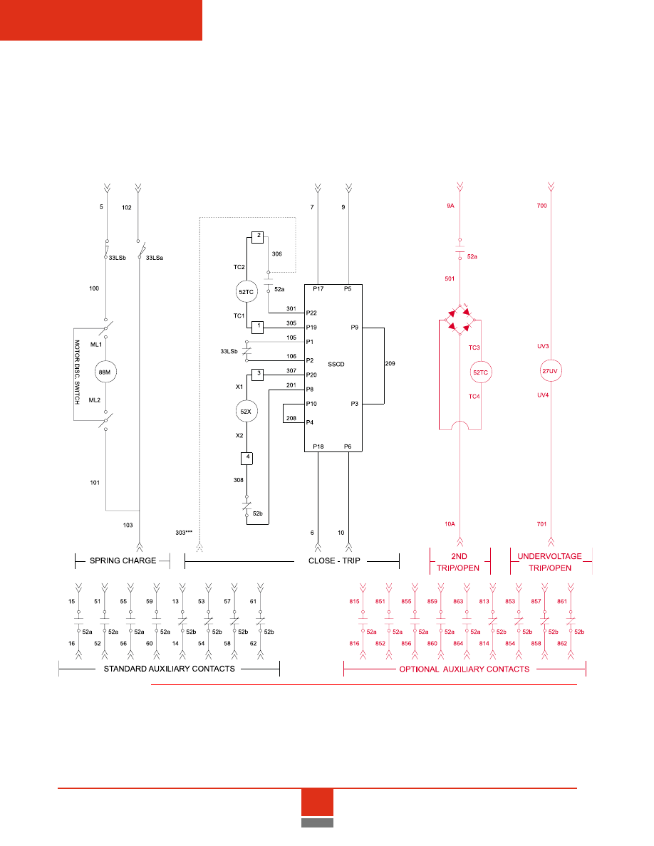
50
Reference
Circuit
Breaker
Schematic
Diagram
ADVAC circuit breakers are available with two schematic
diagrams. The basic schematic diagram is supplied with a
single secondary disconnect. Additional auxiliary contacts, a
second shunt trip device, and an undervoltage trip device are
options that are available with the dual secondary disconnect.
LEGEND
LEGEND
LEGEND
LEGEND
LEGEND
33 LS
33 LS
33 LS
33 LS
33 LS
Spring Charged Limit Switch
27 UV
27 UV
27 UV
27 UV
27 UV
Undervoltage Release
52 TC
52 TC
52 TC
52 TC
52 TC
Trip Coil
52 X
52 X
52 X
52 X
52 X
Close Coil
52 a,b
52 a,b
52 a,b
52 a,b
52 a,b
Auxiliary Contacts (shown breaker open)
88 M
88 M
88 M
88 M
88 M
Spring Charging Motor
SSCD
SSCD
SSCD
SSCD
SSCD
Solid State Control Device
303***
303***
303***
303***
303***
Trip Coil Monitor Wire for optional use
Note: Care must be taken to avoid full
voltage/current to trip coil longer than
pulse duration. Contact factory to order.
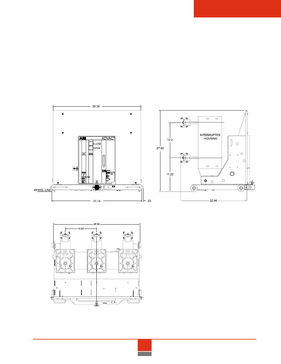
Reference
51
Circuit
Breaker
Outline
Front View
Front View
Front View
Front View
Front View
Side View
Side View
Side View
Side View
Side View
T
T
T
T
Top View
op View
op View
op View
op View
ADVAC circuit breaker dimensions are similar for all 36-inch wide
compartments and ratings. The operating mechanism, control
components, racking system and accessories are the same for all
ratings. Breakers with higher interrupting and continuous current
ratings use various primary lead assemblies and interrupter
housings with different appearances, but cell interface dimensions
are identical. To reduce racking force requirements, some 3000 A
primary contacts are offset slightly to the rear for sequenced
contact engagement.
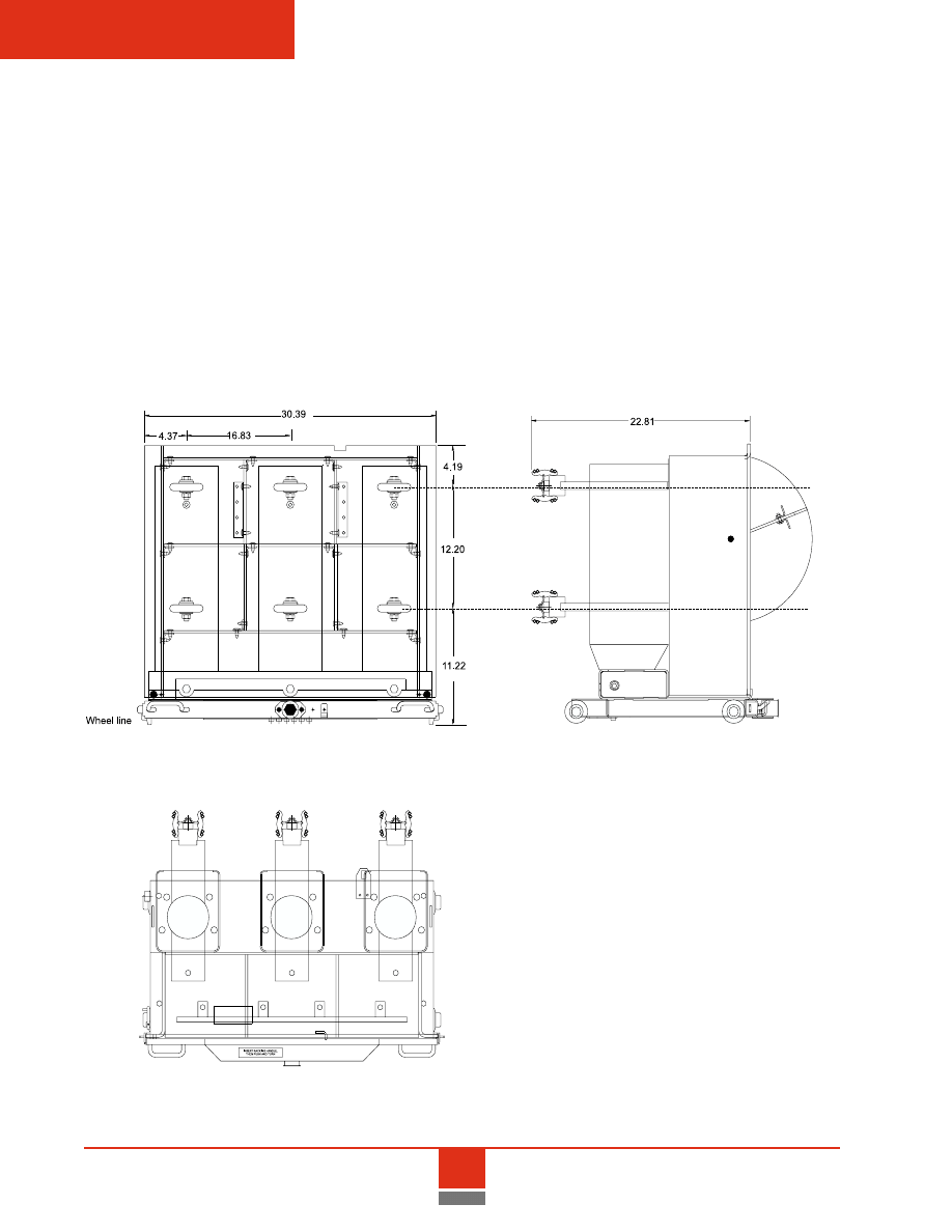
52
Reference
Ground and Test
Device Outline
Front View
Front View
Front View
Front View
Front View
Side View
Side View
Side View
Side View
Side View
T
T
T
T
Top View
op View
op View
op View
op View
NOTES:
NOTES:
NOTES:
NOTES:
NOTES:
1. The device is for use with cells designed for
ADVAC breakers.
2. Two (2) sets of cables are furnished. The short set
attaches to the lower terminal set, and the long set
attaches to the upper terminal set.
3. This device is designed for use with only one set of
cables attached to a terminal set at any given time.
Either the upper terminals are grounded through
their cable set, or the lower terminals are grounded
through their cable set.
4. Position stops are provided in the Connected and
Disconnected positions. To assure that the device
is in the fully Connnected position, the "Connect"
label must be in the correct position.
5. Device cannot be stored in breaker compart-
ments.
G&T devices are interchangeable with ADVAC circuit breakers in
appropriately rated compartments. These devices provide a
manual means to select and test primary circuits in a controlled
manner, and then ground a set of de-energized primary contacts
to the switchgear ground bus. The racking system can be pad-
locked to keep the G&T in the grounded position during mainte-
nance activity. G&T devices are available with six terminals
(shown below) or three terminals. Three-terminal devices can be
ordered with upper or lower terminals. G&T devices are not
rated for switching or interrupting duty. A single device can be
used for both 1200 A and 2000 A compartments, and a separate
G&T is required for 3000 A compartments.

Reference
53
Typical
Operating
Procedure for
Grounding the
Circuit
1. Disconnect the ground cables from all terminals.
2. Swing the door over the device terminal set that is not
be grounded.
3. Padlock the door in position.
4. Install the device in the switchgear compartment.
5. Close and secure the switchgear door.
6. Rack the device to the Connected position. The device must
be in the fully Connected position. The Connected label must
be in the appropriate position to assure that the device is
installed properly.
7. Open the switchgear door.
8. Test the exposed terminal ends to assure that the terminal set
to be grounded is not energized.
9. After establishing that the exposed terminal set is de-ener-
gized, close the switchgear door, and rack the device to the
Disconnected position.
10. Open the switchgear door, with the device in the Discon-
nected position, and attach the upper or lower ground cables
to the exposed terminal set.
11. With the grounded cables attached, close and secure
the switchgear door and rack the device to the
Connected position.
12. With the ground cables installed and the device racked to the
Connected position, the terminal set connected to the ground
cables is grounded to the switchgear ground bus.

54
Reference
NOTES

655 Century Point
2300 Mechanicsville Highway
Lake Mary, FL 32746
Florence, SC 29501
Tel: +1-407-723-2000
Tel:
+ 843-413-4800
1-800-929-7947
1-800-338-1585
Fax: +1407-732-2161
Fax: +1-843-413-4850
www.abb.com/mediumvoltage
www.abb.com/mediumvoltage
TB3.2.8
-
1B
February
2002
Wyszukiwarka
Podobne podstrony:
03 02
2010 03 02
2014 03 02 11 42 15 01
03 02 (3)
na5 pieszak 03 02 10 1 id 43624 Nieznany
G2 4 PW Odw Rys 03 02
11 01 03 02 ?z d Fzge, Tagbez o L
2014 03 02 11 45 08 01
2014 03 02 Ubezpieczenia w Dzia slajdyid 28512 (2)
IMiR gzamin I z matematyki 03-02-2014
2014 03 02 11 01 14 01
03 02 zakres i sposób rejestracji
G2 4 PW CO Rys 03 02
2014 03 02 11 50 58 01id 28533 Nieznany
wyniki 03-02-14 automatyka i sterowanie
lo orm2 03 02 kp2
2014 03 02 11 43 30 01id 28527 Nieznany
więcej podobnych podstron