Electromagnetic Compatibility
Grzegorz Kosobudzki
; Jerzy Leszczyński
Introduction to EMC

Electromagnetic compatibility (EMC)
the ability of a system or equipment to operate within
design tolerances in its intended environment, with
adjacent systems and equipment, and with itself, so
that the effect of any electromagnetic disturbances
produced by the systems or equipment is reduced.
2
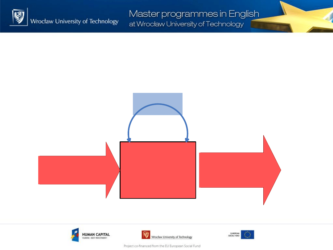
Electromagnetic compatibility (EMC)
Equipement,
Device or
System
Intrasystem
interference
Electromagnetic
disturbances
Electromagnetic
environment
Electromagnetic
disturbances
emmision
Electromagnetic
environment
3
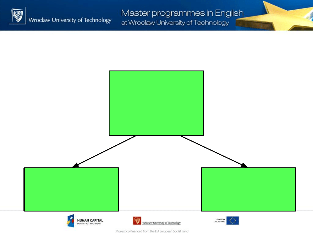
Electromagnetic compatibility (EMC)
Electromagnetic
Compatibility
Electromagnetic
emission
Electromagnetic
susceptibility
4

Electromagnetic interference (EMI)
A phenomenon in which electronic devices upset
each other’s operation. Computers, television
receivers, telephone sets, high-fidelity sound
equipment, and certain medical devices can
malfunction because of strong radio-frequency
fields such as those from a nearby broadcast
transmitter. The EMI is usually the result of
improper or ineffective shielding in the affected
device or system.
5

Electromagnetic compatibility
frequency range
DC
Power line frequency 50,60,400 Hz
Low frequency 50…150kHz
High frequency >150kHz (Radio frequency)
6
The electromagnetic interference (EMI)
coupling channel
7
Source of
electromagnetic
disturbances
Victim
(equipment)
Coupling path
Electromagnetic
(Radiative)
Common impedance (Conductive)
Magnetic field
(Inductive)
Electric field
(Capacitive)
7
Principal phenomena causing electromagnetic disturbances as classified by the IEC
Group
Exemples
Conducted low frequency phenomena Harmonic, interharmonic, DC in AC networks
Signal system (power line carrier)
Voltage dips, interruption,fluctuation, imbalance
Power frequency variation
Induced low frequency voltages
Radiated low frequency phenomena
Magnetic fields, Electric fields
Conducted high frequency
phenomena
Induced continuous wave voltage or current
Oscillatory transient, Unidirectionat transient
Radiated high frequency phenomena
Magnetic fields, Electric fields, electromagnetic fields
Transients, continuous waves
Electrostatic discharge (ESD)
Nuclear electromagnetic pulse (NEMP)
8
Conductive interference
Power Supply
Temperature
sensor
Vo=10mV/
o
C
Vcc
+5V
GND
LOAD
V
m
V
m
=V
o
+V
AB
A
B
I
on
=1A
Shared current path
9
Conductive interference
Power Supply
Temperature
sensor
Vo=10mV/
o
C
Vcc
+5V
GND
LOAD
V
m
V
m
=V
o
A
I
on
=1A
10
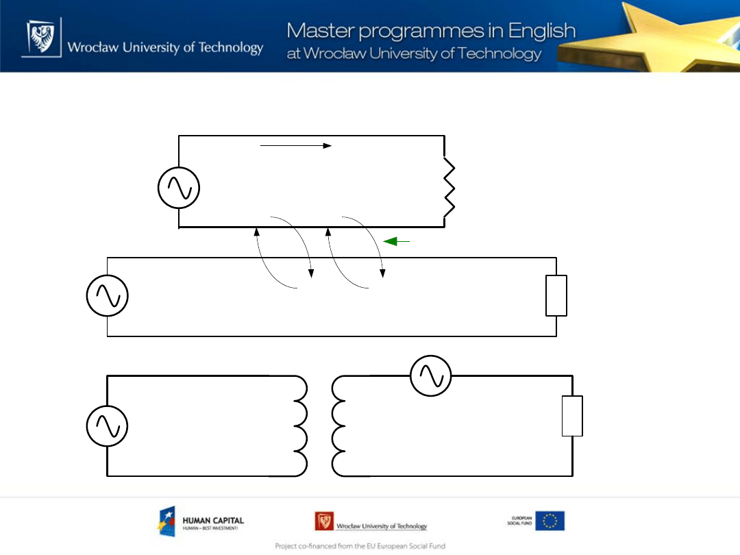
Inductive interference
R
L
Vs - Signal source
Vn - Noise source
Magnetic flux coupling
I
n
M
R
L
Vs
Vn
11
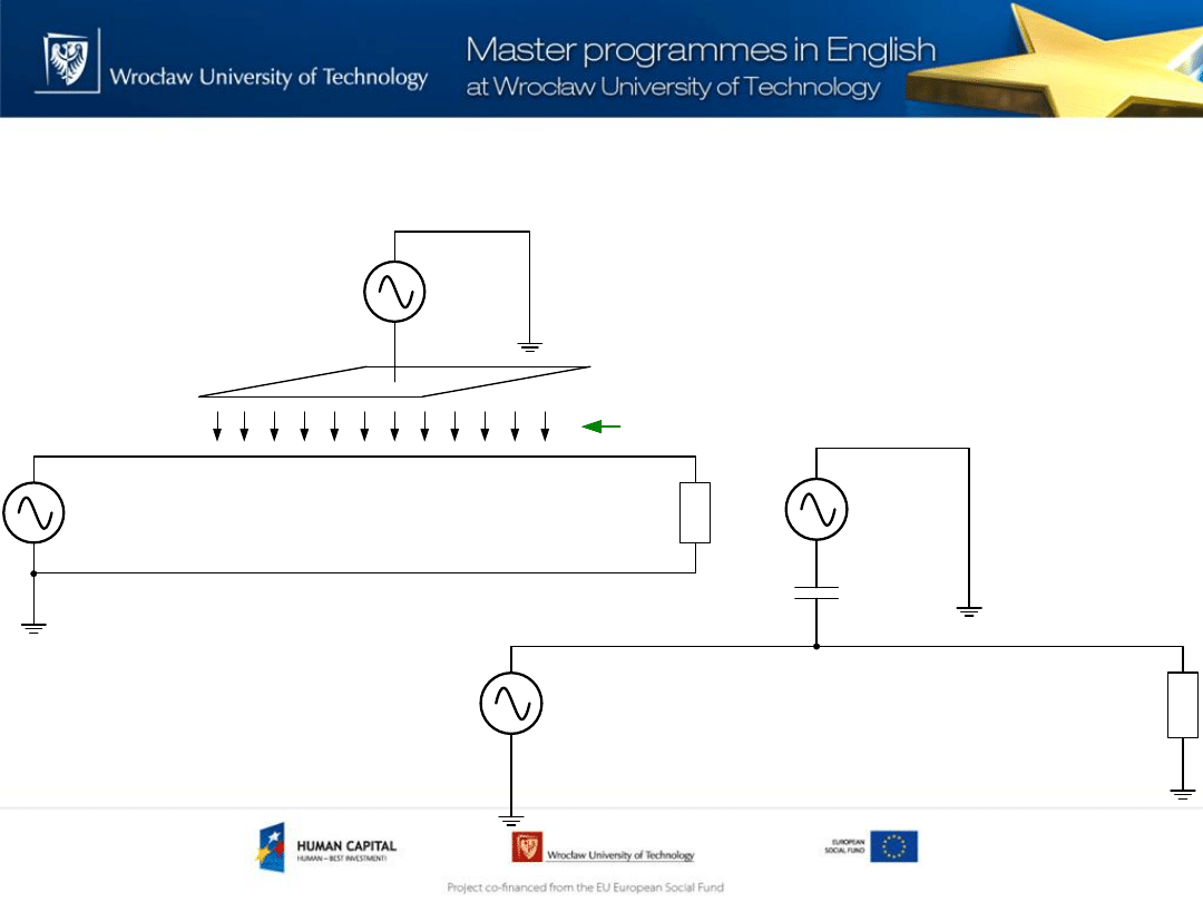
Capacitive interference
R
L
Electrical field
Vs - Signal source
Vn - Noise source
R
L
Vs - Signal source
C
ef
12
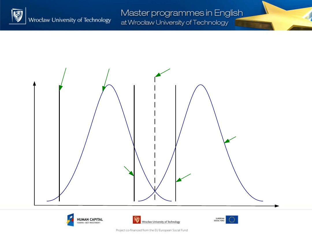
Emission limit,immunity limit, compatibility level
and planning level
P
ro
b
a
b
ili
ty
d
e
n
s
it
y
Disturbance level
Emission
Level
Compatibility
Level
Equipement
Compatibility
Level
Immunity
Limit
Planning
Level
Emission
Limit
13
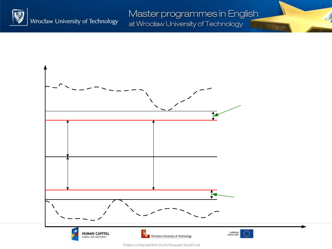
Emission limit,immunity limit, compatibility level
and planning level
D
is
tu
rb
a
n
c
e
L
e
v
e
l
Independent variable
Compatibility Level
Emission Limit
Immunity Limit
Emission Level
Immunity Level
Immunity Margin
Emission Margin
Compatibility Margin
Construction Emission
Margin
Construction Immunity
Margin
14

Power Quality – Part of EMC
Power Quality: The concept of powering and
grounding electronic equipment in a manner that
is suitable to the operation of that equipment and
compatible with premise wiring system and other
connected equipment
IEEE std 1159 definition
15

Power Quality – Part of EMC
Coupling path
– conductive (Power Distribution System )
Equipement: Immunity to disturbances in power system
Emission of disturbances to power system
Environment: power system voltage parameters
16

How to prevent disturbances?
17
•Use shielded gaskets to seal doors and
flanges
•Fit an EMC filter on the incoming power side
•Keep signal cables away from power cables
•Use screened cables and use EMC glands for
360 degree earth bonding on both ends

Electromagnetic compatibility
Overview of Standards (IEC 61000 series)
• 1: General : General consideration (fundamental principles).
• 2: Environment : Description and classification of environment.
Compatatibility levels.
• 3: Emission limits and immunity test levels.
• 4: Testing and measurement techniques.
• 5: Installation and mitigation guidelines.
• 6: Generic standards.
• 9: Miscellaneous.
18

Enviroment
• EN 61000-2-2 - Compatibility levels for low-frequency conducted
disturbances and signalling in public low-voltage power supply
systems.
• EN 61000-2-4 - Compatibility levels in industrial plants for low-
frequency conducted disturbances.
• EN 61000-2-9 - Description of HEMP environment - Radiated
disturbance. Basic EMC publication.
• EN 61000-2-10 - Description of HEMP environment - Conducted
disturbance.
• EN 61000-2-12 -Environment - Compatibility levels for low-frequency
conducted disturbances and signalling in public medium-voltage
power supply systems.
19

Limits
• EN 61000-3-2 - Limits for harmonic current emissions (equipment
input current ≤16 A per phase) .
• EN 61000-3-3 - Limitation of voltage changes, voltage fluctuations
and flicker in public low-voltage supply systems, for equipment with
rated current ≤16 A per phase and not subject to conditional
connection.
• EN 61000-3-11 - Limitation of voltage changes, voltage fluctuations
and flicker in public low-voltage supply systems - Equipment with
rated current ≤ 75 A and subjet to conditional connection.
• EN 61000-3-12 - Limits for harmonic currents produced by equipment
connected to public low-voltage systems with input current > 16 A
and ≤ 75 A per phase.
20

Testing and measurement techniques-1
• EN 61000-4-2 - Electrostatic discharge immunity test.
• EN 61000-4-3:2006 - Radiated, radio-frequency,
electromagnetic field immunity test.
• EN 61000-4-4:2004 - Electrical fast transient/burst
immunity test.
• EN 61000-4-5 –Surge immunity test.
• EN 61000-4-6 -Immunity to conducted disturbances,
induced by radio-frequency fields.
21

Testing and measurement techniques-2
• EN 61000-4-8 - Power frequency magnetic field immunity test.
• EN 61000-4-9 - Pulse magnetic field immunity test.
• EN 61000-4-10 - Damped oscillatory magnetic field immunity test.
• EN 61000-4-11 - Voltage dips, short interruptions and voltage
variations immunity tests .
• EN 61000-4-34 - Voltage dips, short interruptions and voltage
variations immunity tests for equipment with input current more
than 16 A per phase.
• EN 61000-4-14 - Voltage fluctuation immunity test for equipment
with input current not exceeding 16 A per phase.
22
Testing and measurement techniques-3
• EN 61000-4-13 - Harmonics and interharmonics including mains
signalling at a.c. power port, low frequency immunity tests.
• EN 61000-4-12 - Ring wave immunity test .
• EN 61000-4-18:2007 - Damped oscillatory wave immunity test
• EN 61000-4-16 - Test for immunity to conducted, common mode
disturbances in the frequency range 0 Hz to 150 kHz.
• EN 61000-4-17 - Ripple on d.c. input power port immunity test.
• EN 61000-4-20 - Emission and immunity testing in transverse
electromagnetic (TEM) waveguides.
23

Testing and measurement techniques-4
• EN 61000-4-21 - Reverberation chamber test methods.
• EN 61000-4-23 - Test methods for protective devices for HEMP and
other radiated disturbances .
• EN 61000-4-24 - Test methods for protective devices for HEMP
conducted disturbance - Basic EMC Publication.
• EN 61000-4-25 - HEMP immunity test methods for equipment and
systems.
• EN 61000-4-27 - Unbalance, immunity test for equipment with input
current not exceeding 16 A per phase.
• EN 61000-4-28 - Variation of power frequency, immunity test for
equipment with input current not exceeding 16 A per phase .
• EN 61000-4-29 - Voltage dips, short interruptions and voltage
variations on d.c. input power port immunity tests
24

Testing and measurement techniques-5
• EN 61000-4-7 - General guide on harmonics and
interharmonics measurements and instrumentation, for
power supply systems and equipment connected thereto.
• EN 61000-4-15 - Flickermeter - Functional and design
specifications.
• EN 61000-4-30 –Power quality measurement methods.
25

Installation and mitigation guidelines
• EN 61000-5-5 - Specification of protective devices for
HEMP conducted disturbance. Basic EMC Publication.
• EN 61000-5-8 - HEMP protection methods for the
distributed infrastructure.
26

Generic standards
• EN 61000-6-1 - Immunity for residential, commercial and
light-industrial environments.
• EN 61000-6-2 - Immunity for industrial environments.
• EN 61000-6-3 - Emission standard for residential,
commercial and light-industrial environments.
• EN 61000-6-4 - Emission standard for industrial
environments.
27

International Electrotechnical
Commission
The IEC is the world's leading organization that prepares
and publishes International Standards for all electrical,
electronic and related technologies — collectively
known as „electrotechnology”
28

CISPR
The Special International Committee on Radio
Interference (abbreviated CISPR from the French name
of the organization, Comité international spécial des
perturbations radioélectriques) is concerned with
developing norms for detecting, measuring and
comparing electromagnetic interference in electric
devices. Its members are partially also in the
International Electrotechnical Commission (IEC). It was
founded in 1934.
29

References and useful links
• www.iec.ch
• www.pkn.pl
• www.lpqi.org
• www.schaffner.com -> www.teseq.com
• www.miedz.org.pl
• www.reo.co.uk
• www.emtest.com
30

References and useful links
• C. Sankaran – ”Power quality” – CRC press 2002
• A.Baggini –”Handbook of Power Quality” – John Wiley &
Sons 2008
• R.C.Dugan, M.F. McGranaghan, H.W Beaty – „Electrical
Power System Quality”-McGraw-Hill 1996
• Kenneth L. Kaiser – „Electromagnetic Compatibility
Handbook” – CRC Press 2005
31
Wyszukiwarka
Podobne podstrony:
EMC emission v2
EMC emission v2
EMC Spectrum Analyzer v2
ASUS InstantFun Introduction XP EN V2
EMC Spectrum Analyzer v2
IntroductoryWords 2 Objects English
lecture3 complexity introduction
Introduction to VHDL
ZMPST 01 Introduction
DTC v2
Elektro (v2) poprawka
l1213 r iMiBM lakei v2
logika rozw zadan v2
więcej podobnych podstron