Engine
101
1
1
2
2
3
3
4
4
5
5
6
6
7
7
8
8
9
9
10
10
12
12
11
11
13
13
14
14
15
15
16
16
17
17
18
18
19
19
20
20
22
22
21
21
Choose a
Number
23
23
End = Esc


Basic Operaion
A motor has several cavitvities called cylinders. The piston moves up and down in the cylinder
Thus converting vertical movement into rotary movement. This rotary movement is transfered to
The wheels through a gear box to the wheels

The fuel is mixed with air in the carburetor. The air/ fuel mixture is
Then put in the cylinders.
This is called the Intake Stroke

Now the explosive mixture is in the cylinder, it must be crompressed prior to combustion. The piston compresses,
thie mixture.
This is called the:
Compression Stroke

At an exact time, the spark plug ignites the mixture.
This is called the:
Ignition. Stroke

The piston is forced down violently during the ignition stroke then rises again to expell the
Burned gasses. This is the:


Direct injection: JTD, TDI, HDI
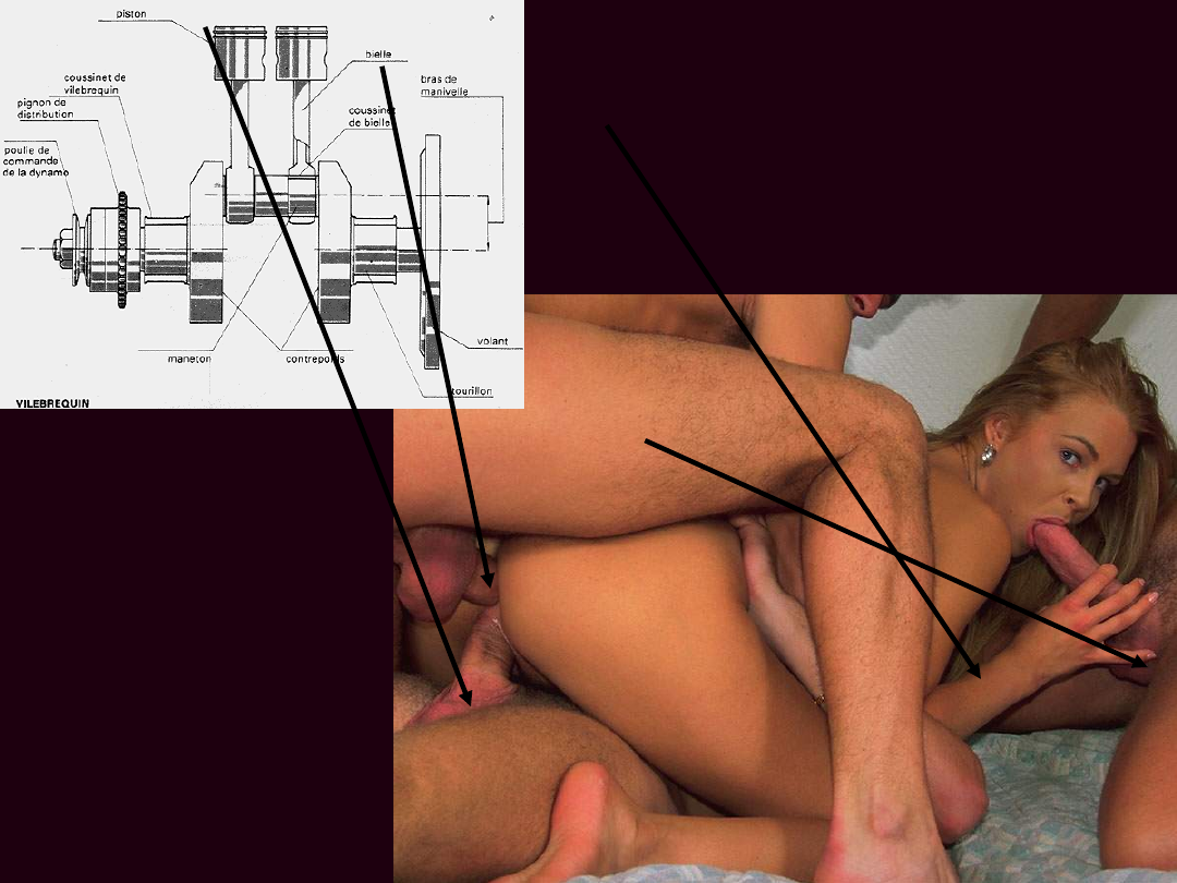
Crank
shaft and
piston
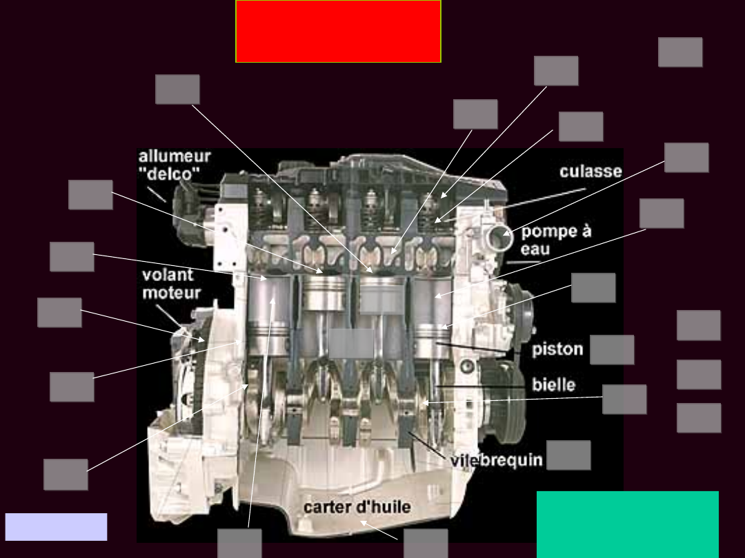
MOTOR
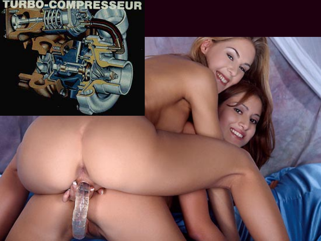
TURBOCHARGER

TWIN TURBO: There are two turbine wheels on one
axis. One is driven by the exhaust fumes, the other
sucks the mixture and pumps it into the cylinder.

This increases the amount of air that injected into
combustion chamber.

Before the INVENTION of the Turbo more
cylinders were needed to boost performance.

Principle of the direct injection: the mixture is injected directly into the cylinder.
The direct injection is possible by the use of a high pressure pump.

This is an example of an IN-LINE 4 CYLINDER Engine
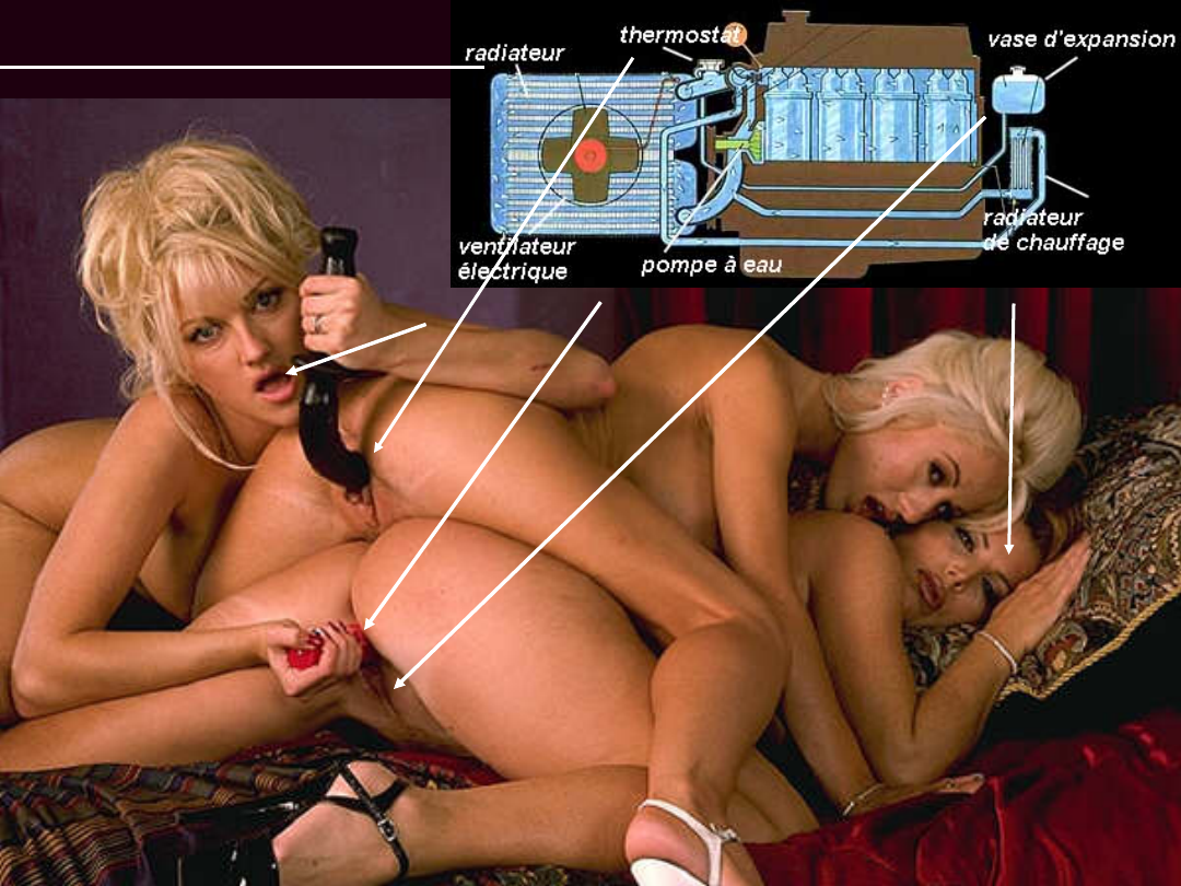
The Cooling System
Document Outline
- PowerPoint Presentation
- Slide 2
- Slide 3
- Slide 4
- Slide 5
- Slide 6
- Slide 7
- Slide 8
- Slide 9
- Slide 10
- Slide 11
- Slide 12
- Slide 13
- Slide 14
- Slide 15
- Slide 16
- Slide 17
- Slide 18
- Slide 19
- Slide 20
- Slide 21
- Slide 22
- Slide 23
Wyszukiwarka
Podobne podstrony:
BUDOWA SILNIKA SPALINOWEGO LOKOMOTYWY ST, Maszynista-Pomocnik maszynisty 2013
28 Budowa silników
Budowa silnika SRM
Budowa silnika, Motoryzacja, Warsztat, Mechanika, SERWIS AUT naprawa
Temat nr 9 - Budowa silników okretowych - wybrane zagadnienia, Silniki okretowe
sciaga budowa silnika 2
Słownictwo związane z budową silnika benzynowego ( GER - PL), MOTORYZACJA, ▼ Silniki Spalinowe ▼
Budowa silnikow spalinowych, MOTORYZACJA
Budowa silnika o zapłonie iskrowym, UTP Transport, III sem, Budowa pojazdów
BUDOWA SILNIKA SPALINOWEGO LOKOMOTYWY ST, Maszynista-Pomocnik maszynisty 2013
Budowa pojazdów samochodowych -Zasada działania silnika dwusuwowego semestr 1, Motoryzacja
Budowa pojazdów samochodowych -Proces spalania w silniku o zapłonie samoczynnym semestr 1, Motoryzac
Budowa pojazdów samochodowych Proces spalania w silniku o zapłonie samoczynnym semestr 1 (2)
Budowa pojazdów samochodowych zasada działania silnika czterosuwowego i?z rozrządu semestr 1 (2)
Budowa i zasada działania układu chłodzenia w silnikach serii K
MAN Silnik D28 budowa
opracowanie oleje silnikowe, Studia, MECHANIKA I BUDOWA MASZYN, Płyny Eksploatacyjne
Model matematyczny podsystemu silnika -Bielski, Mechanika i budowa maszyn, Semestr IX, Praca przejsc
więcej podobnych podstron