English
Deutsch
Français
Nederlands
Español
Italiano
∂ÏÏËÓÈο
Português
Türkçe
Русский
INSTALLATION MANUAL
For safe and correct use, please read this installation manual thoroughly before installing the air-conditioner
unit.
INSTALLATIONSHANDBUCH
Zum sicheren und ordnungsgemäßen Gebrauch der Klimaanlage das Installationshandbuch gründlich
durchlesen.
MANUEL D’INSTALLATION
Veuillez lire le manuel d’installation en entier avant d’installer ce climatiseur pour éviter tout accident et vous
assurer d’une utilisation correcte.
INSTALLATIEHANDLEIDING
Voor een veilig en juist gebruik moet u deze installatiehandleiding grondig doorlezen voordat u de airconditioner
installeert.
MANUALE DI INSTALLAZIONE
Per un uso sicuro e corretto, leggere attentamente questo manuale di installazione prima di installare il condizionatore
d’aria.
MANUAL DE INSTALACIÓN
Para un uso seguro y correcto, lea detalladamente este manual de instalación antes de montar la unidad de
aire acondicionado.
E°XEIPI¢IO O¢H°IøN E°KATA™TA™H™
°È· ·ÛÊ¿ÏÂÈ· Î·È ÛˆÛÙ‹ ¯Ú‹ÛË, ·Ú·Î·Ï›ÛÙ ‰È·‚¿ÛÂÙ ÚÔÛ¯ÙÈο ·˘Ùfi ÙÔ ÂÁ¯ÂÈÚ›‰ÈÔ ÂÁηٿÛÙ·Û˘
ÚÈÓ ·Ú¯›ÛÂÙ ÙËÓ ÂÁηٿÛÙ·ÛË Ù˘ ÌÔÓ¿‰·˜ ÎÏÈÌ·ÙÈÛÌÔ‡.
MANUAL DE INSTALAÇÃO
Para segurança e utilização correctas, leia atentamente este manual de instalação antes de instalar a unidade
de ar condicionado.
MONTAJ ELK‹TABI
Emniyetli ve do¤ru biçimde nas›l kullan›laca¤›n› ö¤renmek için lütfen klima cihaz›n› monte etmeden önce bu
elkitab›n› dikkatle okuyunuz.
РУКОВОДСТВО ПО УСТАНОВКЕ
Для осторожного и правильного использования прибора необходимо тщательно ознакомиться с данным
руководством по установке до выполнения установки кондиционера.
FOR INSTALLER
FÜR INSTALLATEURE
POUR L’INSTALLATEUR
VOOR DE INSTALLATEUR
PER L’INSTALLATORE
PARA EL INSTALADOR
PARA O INSTALADOR
°π∞ ∞À∆√¡ ¶√À ∫∞¡∂π ∆∏¡ ∂°∫∞∆∞™∆∞™∏
MONTÖR ‹Ç‹N
ДЛЯ УСТАНОВИТЕЛЯ
Air-Conditioners For Building Application
INDOOR UNIT
PKFY-P·VFM-E
For use with the R410A, R407C & R22
Bei Verwendung von R410A, R407C & R22
A utiliser avec le R410A, R407C et le R22
Bij gebruik van R410A, R407C & R22
Para utilizar con el R410A, R407C y el R22
Uso del refrigerante R410A, R407C e R22
°È· ¯Ú‹ÛË ÌÂ Ù·
R410A, R407C Î·È R22
Para utilizaçao com o R410A, R407C e o R22
R410A, R407C ve R22 ile beraber kullanmak için
Для использования с моделями R410A, R407С и R22
2
Contents
Fig. 2-1
D
A
C
F
E
H
W
B
s Before installing the unit, make sure you read all the “Safety precau-
tions”.
s Please report to your supply authority or obtain their consent before
connecting this equipment to the power supply system.
Warning:
Describes precautions that must be observed to prevent danger of injury or
death to the user.
Caution:
Describes precautions that must be observed to prevent damage to the unit.
After installation work has been completed, explain the “Safety Precautions,” use,
and maintenance of the unit to the customer according to the information in the Op-
eration Manual and perform the test run to ensure normal operation. Both the Instal-
lation Manual and Operation Manual must be given to the user for keeping. These
manuals must be passed on to subsequent users.
2. Installation location
Warning:
• Ask the dealer or an authorized technician to install the air conditioner.
• Install the unit at a place that can withstand its weight.
• Use the specified cables for wiring.
• Use only accessories authorized by Mitsubishi Electric and ask the dealer or
an authorized technician to install them.
• Do not touch the heat exchanger fins.
• Install the air conditioner according to this Installation Manual.
• Have all electric work done by a licensed electrician according to local regu-
lations.
• If the air conditioner is installed in a small room, measures must be taken to
prevent the refrigerant concentration from exceeding the safety limit even if
the refrigerant should leak.
• The cut face punched parts may cause injury by cut, etc. The installers are
requested to wear protective equipement such as gloves, etc.
1. Safety precautions ................................................................................... 2
2. Installation location .................................................................................. 2
3. Installing the indoor unit ........................................................................... 3
4. Refrigerant pipe ....................................................................................... 5
5. Drainage piping work (Fig. 5-1) ................................................................ 6
6. Electrical work .......................................................................................... 6
7. Test run .................................................................................................... 8
1. Safety precautions
: Indicates an action that must be avoided.
: Indicates that important instructions must be followed.
: Indicates a part which must be grounded.
: Indicates that caution should be taken with rotating parts.
: Indicates that the main switch must be turned off before servicing.
: Beware of electric shock.
: Beware of hot surface.
ELV
: At servicing, please shut down the power supply for both the Indoor and
Outdoor Unit.
Warning:
Carefully read the labels affixed to the main unit.
Caution:
• Do not use the existing refrigerant piping, when use R410A or R407C refrig-
erant.
• Use ester oil, either oil or alkylbenzene (small amount) as the refrigerator oil
to coat flares and flange connections, when use R410A or R407C refrigerant.
• Do not use the air conditioner where food, pets, plants, precision instruments,
or artwork are kept.
• Do not use the air conditioner in special environments.
• Ground the unit.
• Install an leak circuit breaker, as required.
• Use power line cables of sufficient current carrying capacity and rating.
• Use only a circuit breaker and fuse of the specified capacity.
• Do not touch the switches with wet fingers.
• Do not touch the refrigerant pipes during and immediately after operation.
• Do not operate the air conditioner with the panels and guards removed.
• Do not turn off the power immediately after stopping operation.
The indoor unit should be supplied with the following accessories.
PARTNUMBER
ACCESSORY
QUANTITY
LOCATION OF SETTING
1
Wall-fixing bracket
1
Fix at the back of the unit
2
Tapping screw 4
× 35
12
3
Insulation material
2
4
Band
4 (large) + 3 (small)
5
Felt tape
3
6
Drain socket
1
7
Wireless remote controller
1
8
Remote controller holder
1
9
Alkali batteries
2
0
Flare nut
P100
1 (ø19.05)
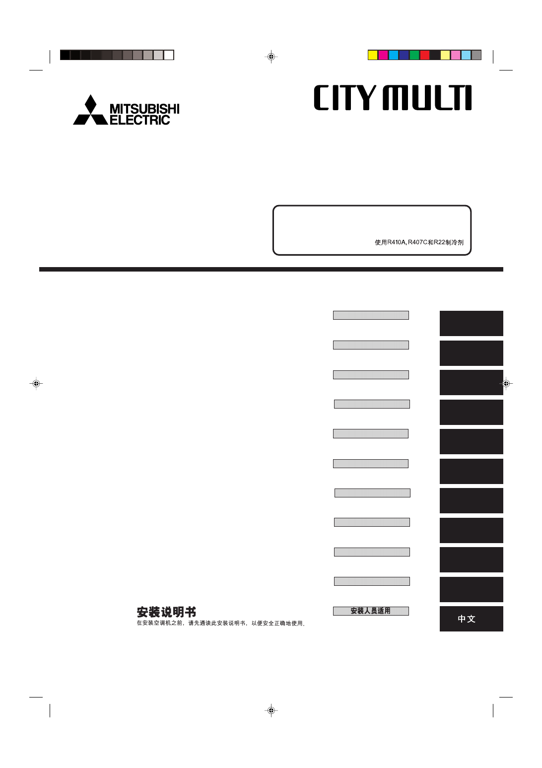
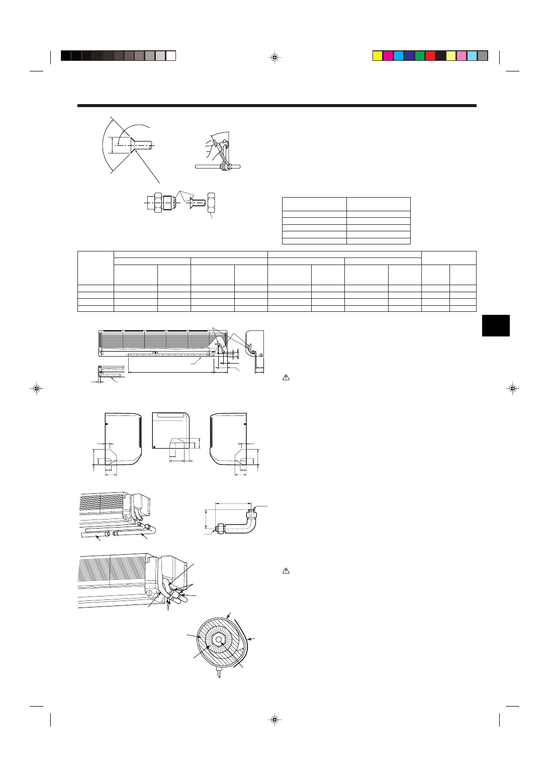
2.1. Outline dimensions (Indoor unit) (Fig. 2-1)
Select a proper position allowing the following clearances for installation and mainte-
nance.
(mm)
Models
W
D
H
A
B
C
E
F
P63
1400
235
340
Min. 150
Min. 50
Min. 30
Min. 250 Min. 150
P100
1680
235
340
Min. 150
Min. 50
Min. 30
Min. 250 Min. 150
Warning:
Mount the indoor unit on a ceiling strong enough to withstand the weight of the
unit.
Set inside the unit
3
3. Installing the indoor unit
990
245
285
455
10
×91=(910)
19
10
184
280
60
30
30
30
29
80
900
91
90
610
314
280
180
240
225
18
18
A
B
C
G
I
H
F
E
D
1270
18 18
900
19
91
295
225
240
180
280
314
90
750
60
280
80
29
30
30
30
10
184
13
×91=(1183)
245
285
595
I
H
H
E
D
B
G
A
C
F
1 P63
(mm)
A
C
D
E
B
2 P100
Fig. 3-1
Fig. 3-2
3.1. Installing the wall mounting fixture (Fig. 3-1)
1) Setting the wall mounting fixture and piping positions
s Using the wall mounting fixture, determine the unit’s installation position
and the locations of the piping holes to be drilled.
Warning:
Before drilling a hole in the wall, you must consult the building contractor.
A Indoor unit center line
B Left drain range
C Right drain range
D Hole for tapping screw
E Bolt hole
F Hole for tapping screw
G Contour of the unit
H Knockout hole for left rear piping
I Rear piping access hole (90-100 mm dia.)
2) Drilling the piping hole (Fig. 3-2)
s Use a core drill to make a hole of 90-100 mm diameter in the wall in the
piping direction, at the position shown in the diagram to the left.
s The hole should incline so that the outside opening is lower than the inside
opening.
s Insert a sleeve (with a 90 mm diameter and purchased locally) through the
hole.
Note:
The purpose of the hole’s inclination is to promote drain flow.
A Sleeve
B Hole
C (Indoors)
D Wall
E (Outdoors)
3) Installing the wall mounting fixture
s Since the indoor unit weighs near 30 kg, selection of the mounting location
requires thorough consideration. If the wall does not seem to be strong
enough, reinforce it with boards or beams before installation.
s The mounting fixture must be secured at both ends and at the centre, if
possible. Never fix it at a single spot or in any nonsymetrical way.
(If possible, secure the fixture at all the positions marked with a bold arrow.)
(Fig. 3-3)
s Secure the wall mounting fixture through its middle row of 12-mm-dia. holes
using locally purchased bolts (through bolts, bolt anchor and nut anchor) of
M10 or W3/8 threading. The bolt tip must not protrude by more than
15 mm from the wall surface. (Fig. 3-4)
Use at least two bolts for a concrete wall, and at least four bolts for a foamed
concrete wall.
A Wall-fixing bracket
B Mounting bolt
C Wall
Warning:
If possible, secure the fixture at all the positions marked with a bold arrow.
Caution:
The unit body must be mounted horizontally.
3.2. Preparation for piping connection
Remove the vinyl band that holds the drain piping.
• This vinyl band can be used to temporarily attach the pipes to the wall mounting
fixture while connecting the left pipe.
1) Rear, right and lower piping (Fig. 3-5)
1 Remove the right side panel.
2) Left and left rear piping
1 Remove the side panel.
1
Fig. 3-3
Fig. 3-4
Fig. 3-5
Min.165
Min.60
Min.500
A
Min.165
Min.60
Min.500
A
Max.15
C
B
1 P63
2 P100
A
4
1
3
2
D
C
Fig. 3-10
A
E
B
3. Installing the indoor unit
D
D
B
C
D
2
3
B
C
A
5
4
3
2
1
E
F
∗
4
G
I
K
J
H
K
I
G
H
Fig. 3-6
Fig. 3-8
Fig. 3-9
Fig. 3-7
When embedding pipes into the wall (Fig. 3-6)
When the refrigerant pipe, drain pipes, internal/external connection lines, etc., are to
be embedded into the wall in advance, the extruding pipes, etc., may have to be bent
and have their length modified to the unit.
• Make the pipes to be embedded slightly longer than necessary, and install.
A Right side panel
C On-site piping
B Through hole
D Wall-fixing bracket 1
2 Remove the five screws indicated by the arrows in the diagram. (Fig. 3-7)
3 Remove the left side panel, then the lower panel.
1. While pushing up the front lower portion of the side panel (to disengage the side
panel catch from the unit catch), slide the upper portion of the side panel to the
left.
• When the indoor unit is already mounted, be sure the unit does not fall from the wall
mounting fixture.
• For reassembly, put the catch at the front lower portion of the side panel over the
unit body and push it to the right.
A Grille
D Catch
B Left side panel
E Side panel
C Lower panel
F Unit body
∗ Structure of the side panel and the unit body (Fig. 3-8)
1. Panel catch engages the unit body catch.
2. Panel catch is put in the unit body hole.
3. Panel catch engages the unit body catch.
4. Sheet metal of the unit body enters the panel.
5. Panel catch enters the unit body hole.
4 The drain hose can be connected at two different positions. Use the most conven-
ient position and, if necessary, exchange the position of the drain pan, rubber plug
and the drain hose. (Fig. 3-9)
G Drain pan
H Band
I Plug
J Drain hose
K Screwdriver
3.3. Mounting the indoor unit (Fig. 3-10)
1 Make sure to hang the metal catches of the indoor unit over the hooks of the wall
mounting fixture.
2 When the piping has been completed, use the securing screws to fix the indoor
unit on the wall mounting fixture.
Note:
Check that the catches of the indoor unit securely fit over the hooks of the wall
mounting fixture.
3 The screw indicated by the bold arrow is used only during transportation and
should be removed. Remove the screw before installation if there is not enough
space at the left side to remove it once the unit has been installed.
A Indoor unit
B Wall fixing bracket 1
C Hook
D Metal catch of the indoor unit
E Securing screws
5
4. Refrigerant pipe
90
°
±
0.5
°
ø
A
R0.4~R0.8
A
45
°±2°
B
Fig. 4-1
4.1. Connecting pipes (Fig. 4-1)
• When commercially available copper pipes are used, wrap liquid and gas pipes
with commercially available insulation materials (heat-resistant to 100 °C or more,
thickness of 12 mm or more).
• The indoor parts of the drain pipe should be wrapped with polyethylene foam insu-
lation materials (specific gravity of 0.03, thickness of 9 mm or more).
• Apply thin layer of refrigerant oil to pipe and joint seating surface before tightening
flare nut.
• Use two wrenches to tighten piping connections.
• Use refrigerant piping insulation provided to insulate indoor unit connections. Insu-
late carefully.
C
B
A Flare cutting dimensions
Copper pipe O.D.
Flare dimensions
(mm)
øA dimensions (mm)
ø6.35
8.7 - 9.1
ø9.52
12.8 - 13.2
ø12.7
16.2 - 16.6
ø15.88
19.3 - 19.7
ø19.05
22.9 - 23.3
C Apply refrigerating machine oil over the entire flare seat surface.
B Refrigerant pipe sizes & Flare nut tightening torque
* Use the provided flare nut for the following pipes: Liquid pipe of P50, gas pipe of P50, P100, and P125.
P20/25/32/40
P50
P63/80
P100/125
Flare nut O.D.
Liquid
Gas
pipe
pipe
(mm)
(mm)
17
26
22
29
22
29
22
36
R410A
Liquid pipe
Gas pipe
Tightening
Tightening
Pipe size
torque
Pipe size
torque
(mm)
(N.m)
(mm)
(N.m)
ODø6.35 (1/4”)
14 - 18
ODø12.7 (1/2”)
49 - 61
ODø6.35 (1/4”)
34 - 42
ODø12.7 (1/2”)
68 - 82
ODø9.52 (3/8”)
34 - 42
ODø15.88 (5/8”)
68 - 82
ODø9.52 (3/8”)
34 - 42
ODø15.88 (5/8”)
100 - 120
R407C or R22
Liquid pipe
Gas pipe
Tightening
Tightening
Pipe size
torque
Pipe size
torque
(mm)
(N.m)
(mm)
(N.m)
ODø6.35 (1/4”)
14 - 18
ODø12.7 (1/2”)
49 - 61
ODø9.52 (3/8”)
34 - 42*
ODø15.88 (5/8”)
68 - 82*
ODø9.52 (3/8”)
34 - 42
ODø15.88 (5/8”)
68 - 82
ODø9.52 (3/8”)
34 - 42
ODø19.05 (3/4”)
100 - 120*
4.2. Positioning refrigerant and drain piping
1 Position of refrigerant and drain piping (Fig. 4-2)
2 Determine the position of the knockout holes on the unit body (Fig. 4-3)
• Make the knockout holes using a saw blade or an adequate knife.
Caution:
The side panel must be removed before drilling a knockout hole in it.
If a hole is made with the side panel in place, the refrigerant pipe within the unit
could be damaged.
3 L-shaped connection pipe (for gas piping) (Fig. 4-4)
A 107 mm (P63), 102 mm (P100)
H For lower-side piping
B Drain hose
I For right-side piping
C Liquid pipe
J L-shaped connection pipe (option)
D Gas pipe
K Unit side
E Drain hose in left-side piping
L On-site piping side
F Knockout holes on the unit body
M Piping
G For left-side piping
4.3. Refrigerant piping (Fig. 4-5)
1) Indoor unit
Caution:
Before connecting right, lower, left or left rear piping, connect the supplied L-
shaped connection pipe B to the on-site piping.
Liquid pipe
Gas pipe
Insulation material 3
Band (large) 4
Band (small) 4
Band (small) 4
Tape
Thermal insulating
material for
refrigerant piping
Thermal insulating
material for liquid pipe
Liquid pipe
Fig. 4-5
25
1110
183
120
55
42
58
111
C
D
A
D
C
B
B
B
E
1
Fig. 4-2
2
30
37
74
100
39
4
30
37
74
39
98
32
37
65
100
39
4
G
F
H
I
3
Fig. 4-3
Fig. 4-4
J
M
K
J
L
340
80
6
ø
20
O.D
Drain socket
Apply PVC adhesive
On-site drain pipe
Unit’s drain pipe
Felt tape 5
Liquid pipe
Drain pipe
Gas pipe
5. Drainage piping work (Fig. 5-1)
Fig. 5-1
• Drain pipes should have an inclination of 1/100 or more.
• Use PVC pipe VP-20 (O.D. ø26 PVC TUBE) for drain piping.
• Drain pipes can be cut with a knife at the connection point according to the on-site
conditions.
• When connecting the VP-20, use adhesive to attach the supplied drain socket.
• To prevent dripping condensation, put felt tape 5 over the insulation materials on
the refrigerant and drain pipes within the unit as shown in the diagram.
Caution:
The drain pipe should be installed according to this Installation Manual to en-
sure correct drainage. Thermal insulation of the drain pipes is necessary to
prevent condensation. If the drain pipes are not properly installed and insu-
lated, condensation may drip on the ceiling, floor or other possessions.
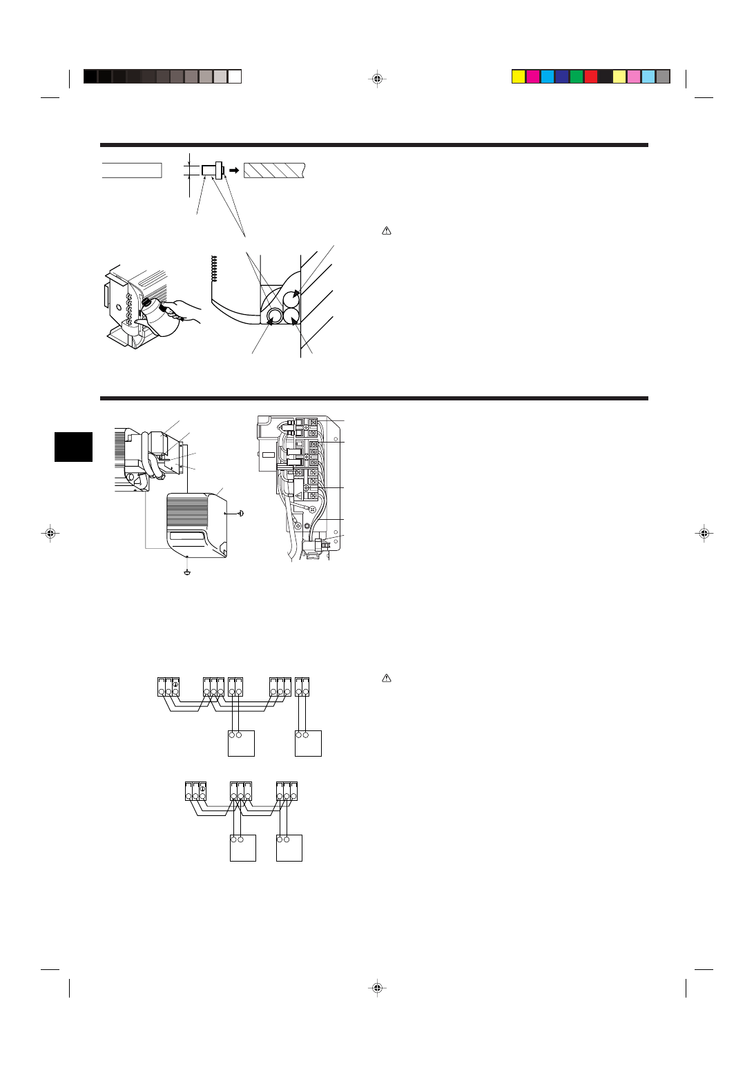
6. Electrical work
A
B
C
D
E
J
I
H
F
G
A Terminal block cover
F Terminal block for MA Remote controller
B Securing screw on the terminal block cover G Terminal block for transmission
C Wire fastening band
H Terminal block for power supply
D Printed circuit board cover
I Power supply wiring & connection wiring
E Right side panel
J Cord clamp
6.1. Indoor unit (Fig. 6-1)
1 Remove the right side panel.
To do this, remove the screws on the lower and right sides.
Remove the securing screw on the terminal block cover to take away the cover.
• The top end is hanging on a catch. Slide the cover to the right and upward for
removal.
2 Connect the power line, control line from the outdoor unit, and remote con-
trol lines.
After connecting, secure the wires with the cable band.
s Fix power source wiring to control box using buffer bushing for tensile force.
(PG connection or the like.)
• Since the electric box may need to be pulled out for servicing or other occasions,
wires must have enough slack.
• Class 3 grounding work must be conducted (grounding wire diameter: 1.6 mm or
more)
After wiring is completed, reinstall the parts in the reverse order of removal.
Note:
• Power supply codes of appliance shall not be lighter than design 245 IEC 53
or 227 IEC 53.
• Install an earth longer and thicker than other cables.
• Power cable size: more than 1.5 mm
2
.
• A means for the disconnection of the supply with an isolation switch, or simi-
lar device, in all active conductors shall be incorporated in the fixed wiring.
• Selecting non-fuse breaker (NF) or earth leakage breaker (NV).
• A switch with at least 3 mm contact separation in each pole shall be provided
by the air conditioner installation.
Warning:
Wiring should be done so that the power lines are not subject to tension. Oth-
erwise, heat may be generated or fire may occur.
6.2. Connecting remote controller, indoor and outdoor
transmission cables (Fig. 6-2)
• Connect indoor unit TB5 and outdoor unit TB3. (Non-polarized 2-wire)
The “S” on indoor unit TB5 is a shielding wire connection. For specifications about
the connecting cables, refer to the outdoor unit installation manual.
• Install a remote controller following the manual supplied with the remote controller.
• Connect the remote controller’s transmission cable within 10 m using a 0.75 mm
2
core cable. If the distance is more than 10 m, use a 1.25 mm
2
junction cable.
1 MA Remote controller
• Connect the “1” and “2” on indoor unit TB15 to a MA remote controller. (Non-polar-
ized 2-wire)
• DC 9 to 13 V between 1 and 2 (MA remote controller)
2 M-NET Remote controller
• Connect the “M1” and “M2” on indoor unit TB5 to a M-NET remote controller. (Non-
polarized 2-wire)
• DC 24 to 30 V between M1 and M2 (M-NET remote controller)
A Terminal block for indoor transmission cable
B Terminal block for outdoor transmission cable
C Remote controller
Fig. 6-1
Fig. 6-2
1
2
A
A
C
TB5
TB15 TB5
TB15
S
M1 M2
S
M1 M2
B
TB3
M1 M2
2
1
C
2
1
A
A
C
TB5
TB5
S
M1 M2
S
M1 M2
C
B
TB3
M1 M2
7
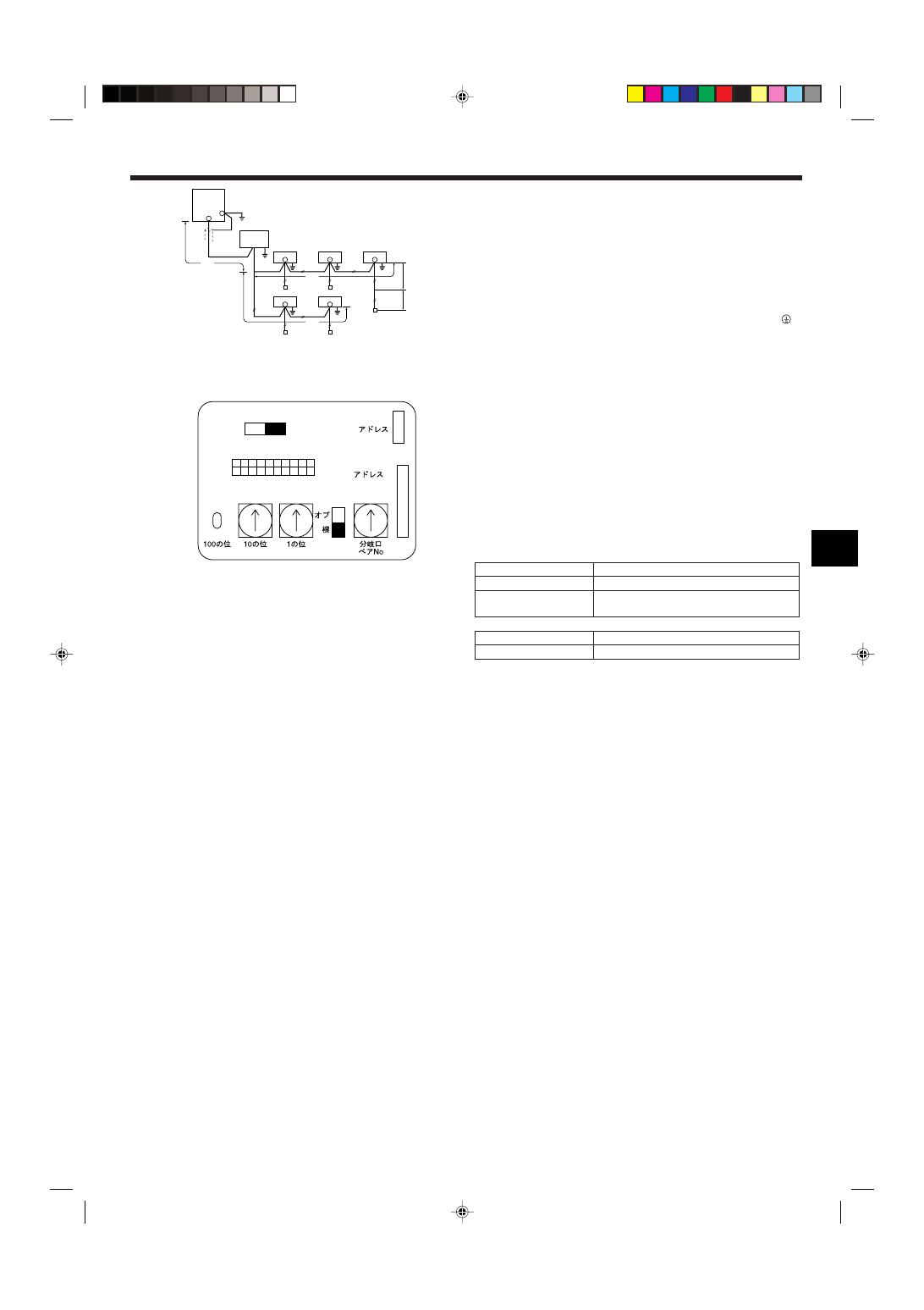
6. Electrical work
Constraints on transmission cable (Fig. 6-3)
Longest wiring length (L
1
+L
2
+L
4
or L
1
+L
3
or L
2
+L
3
+L
4
): less than 200 m
Length between indoor unit and remote controller (
R): within 10 m
G Outdoor unit
H Earth
I BC controller
J Indoor unit
K M-NET Remote controller
L Non-polarized 2-wire
Note:
*1 Put the transmission cable earth via the outdoor unit’s earth terminal
to
the ground.
*2 If the remote controller cable exceeds 10 m, use a 1.25 mm
2
diameter cable
over the exceeded portion, and add that exceeded portion to within 200 m.
*3 The BC controller is required only for simultaneous cooling and heating
series R2.
6.3. Setting addresses (Fig. 6-4)
(Be sure to operate with the main power turned OFF.)
• There are two types of rotary switch setting available: setting addresses 1 to 9 and
over 10, and setting branch numbers.
Note:
Please set the switch SW5 according to the power supply voltage.
• Set SW5 to 240 V side when the power supply is 230 and 240 volts.
• When the power supply is 220 volts, set SW5 to 220 V side.
A Address board
6.4. Types of control cables
1. Wiring transmission cables: Shielding wire CVVS or CPEVS
• Cable diameter: More than 1.25 mm
2
2. M-NET Remote control cables
Kind of remote control cable Shielding wire MVVS
Cable diameter
More than 0.5 to 1.25 mm
2
Remarks
When 10 m is exceeded, use cable with the same
specifications as transmission line wiring.
3. MA Remote control cables
Kind of remote control cable 2-core cable (unshielded)
Cable diameter
0.3 to 1.25 mm
2
Fig. 6-3
A
Fig. 6-4
G
I
J
J
J
K
K
K
K
J
J
L
K
H
*1
*3
L1
L2
L4
r
L3
*2
SW14
0
SW11
0
SW12
0
1 2 3 4 5 6 7 8 9 10
ON
OFF
SW1
SW5
220V
240V
SWC
CN82
CN43
8
7. Test run
7.1. Before test run
s After completing installation and the wiring and piping of the indoor and
outdoor units, check for refrigerant leakage, looseness in the power supply
or control wiring, wrong polarity, and no disconnection of one phase in the
supply.
s Use a 500-volt megohmmeter to check that the resistance between the power
supply terminals and ground is at least 1.0 M
Ω.
s Do not carry out this test on the control wiring (low voltage circuit) termi-
nals.
Warning:
Do not use the air conditioner if the insulation resistance is less than 1.0 M
Ω.
Insulation resistance
7.2. Test run
The following 3 methods are available.
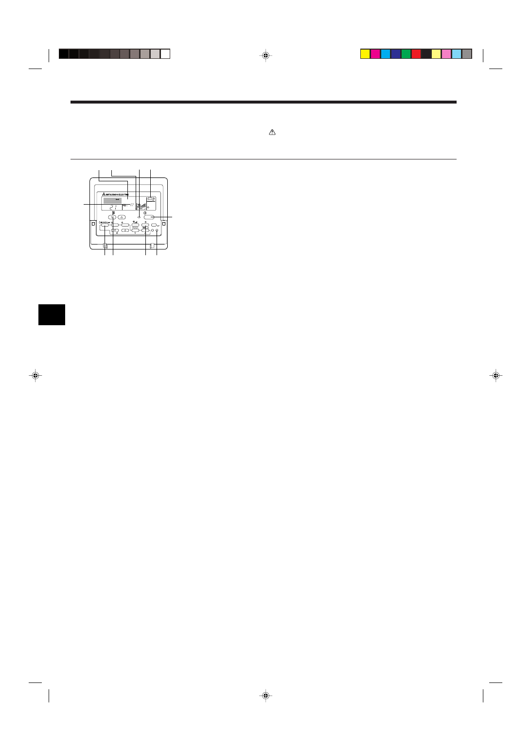
7.2.1. Using wired remote controller (Fig. 7-1)
1 Turn on the power at least 12 hours before the test run.
2 Press the [TEST] button twice.
➡ “TEST RUN” liquid crystal display
3 Press the [Mode selection] button.
➡ Make sure that wind is blown out.
4 Press the [Mode selection] button and switch to the cooling (or heating) mode.
➡ Make sure that cold (or warm) wind is blown out.
5 Press the [Fan speed] button.
➡ Make sure that the wind speed is switched.
6 Check operation of the outdoor unit fan.
7 Release test run by pressing the [ON/OFF] button.
➡ Stop
8 Register a telephone number.
The telephone number of the repair shop, sales office, etc., to contact if an error
occurs can be registered in the remote controller. The telephone number will be
displayed when an error occurs. For registration procedures, refer to the operation
manual for the indoor unit.
Note:
• If an error code is displayed on the remote controller or if the air conditioner
does not operate properly, refer to the outdoor unit installation manual or
other technical materials.
• The OFF timer is set for the test run to automatically stop after 2 hours.
• During the test run, the time remaining is shown in the time display.
• During the test run, the temperature of the indoor unit refrigerant pipes is
shown in the room temperature display of the remote controller.
• When the VANE or LOUVER button is pressed, the message “NOT AVAIL-
ABLE” may appear on the remote controller display depending on the indoor
unit model, but this is not a malfunction.
Fig. 7-1
˚C
˚C
SIMPLE
PAR-21MAA
ON/OFF
FILTER
CHECK
OPERATION
CLEAR
TEST
TEMP.
MENU
BACK
DAY
MONITOR/SET
CLOCK
ON/OFF
TEST RUN
COOL, HEAT
A
F
C
E
D B
M
I
H G
A ON/OFF button
B Test run display
C Indoor temperature liquid line
temperature display
D ON/OFF lamp
E Power display
F Error code display
Test run remaining time dis-
play
G Set temperature button
H Mode selection button
I Fan speed button
M TEST button

Please be sure to put the contact address/telephone number on
this manual before handing it to the customer.
• Low Voltage Directive 73/23/ EEC
• Electromagnetic Compatibility Directive 89/
336/ EEC
This product is designed and intended for use in the residential,
commercial and light-industrial environment.
HEAD OFFICE: TOKYO BLDG., 2-7-3, MARUNOUCHI, CHIYODA-KU, TOKYO 100-8310, JAPAN
Printed in Japan
BG79U776H01
The product at hand is
based on the following
EU regulations:
Wyszukiwarka
Podobne podstrony:
IM PKFY P32 50VGM E BG79U323H02 GB 2004
IM PKFY P20 25VBM E RG79D177H01 GB 2007
IM PCFY P40 125VKM E RG79D452H01 GB 01 2009
IM PEFY P15 63VMS1 L E KB79H130H03 GB 08 2009
IM PAC IF011B E IF012B E BH79D099H02 GB 09 2009
IM CMY R100 200VBK WT05221X02 GB Dec 2008
IM MSZ FD25 35VA SG79Y970H07 GB 2007
IM PEFY P40 250VMH E WT04198X02 GB 2005
IM MUZ MSZ GB50VA SG79Y676H01 EN 2006
IM MSZ GA50 71VA SG79Y434H01 GB 07 2005
IM MXZ 2A30 52VA SG79Y760H04 GB 04 2009
IM MS MSH GD80VB JG79A087H01 GB 04 2008
IM PFFY P20 63VLRMM E WT05228X01 GB 2007
IM PKFY P32 50VHM E RG79D439H03 Aug 2009
IM PUHZ RP200 250YHA BG79U637H03 GB 03 2007
IM MSZ GA22 35 MUZ 25 35VA SG79Y421H01 GB Nov 2006
więcej podobnych podstron