English
Deutsch
Français
Nederlands
Español
Italiano
∂ÏÏËÓÈο
Português
Türkçe
Русский
INSTALLATION MANUAL
For safe and correct use, please read this installation manual thoroughly before installing the air-conditioner
unit.
INSTALLATIONSHANDBUCH
Zum sicheren und ordnungsgemäßen Gebrauch der Klimaanlage das Installationshandbuch gründlich
durchlesen.
MANUEL D’INSTALLATION
Veuillez lire le manuel d’installation en entier avant d’installer ce climatiseur pour éviter tout accident et vous
assurer d’une utilisation correcte.
INSTALLATIEHANDLEIDING
Voor een veilig en juist gebruik moet u deze installatiehandleiding grondig doorlezen voordat u de airconditioner
installeert.
MANUALE DI INSTALLAZIONE
Per un uso sicuro e corretto, leggere attentamente questo manuale di installazione prima di installare il condizionatore
d’aria.
MANUAL DE INSTALACIÓN
Para un uso seguro y correcto, lea detalladamente este manual de instalación antes de montar la unidad de
aire acondicionado.
E°XEIPI¢IO O¢H°IøN E°KATA™TA™H™
°È· ·ÛÊ¿ÏÂÈ· Î·È ÛˆÛÙ‹ ¯Ú‹ÛË, ·Ú·Î·Ï›ÛÙ ‰È·‚¿ÛÂÙ ÚÔÛ¯ÙÈο ·˘Ùfi ÙÔ ÂÁ¯ÂÈÚ›‰ÈÔ ÂÁηٿÛÙ·Û˘
ÚÈÓ ·Ú¯›ÛÂÙ ÙËÓ ÂÁηٿÛÙ·ÛË Ù˘ ÌÔÓ¿‰·˜ ÎÏÈÌ·ÙÈÛÌÔ‡.
MANUAL DE INSTALAÇÃO
Para segurança e utilização correctas, leia atentamente este manual de instalação antes de instalar a unidade
de ar condicionado.
MONTAJ ELK‹TABI
Emniyetli ve do¤ru biçimde nas›l kullan›laca¤›n› ö¤renmek için lütfen klima cihaz›n› monte etmeden önce bu
elkitab›n› dikkatle okuyunuz.
РУКОВОДСТВО ПО УСТАНОВКЕ
Для осторожного и правильного использования прибора необходимо тщательно ознакомиться с данным
руководством по установке до выполнения установки кондиционера.
FOR INSTALLER
FÜR INSTALLATEURE
POUR L’INSTALLATEUR
VOOR DE INSTALLATEUR
PER L’INSTALLATORE
PARA EL INSTALADOR
PARA O INSTALADOR
°π∞ ∞À∆√¡ ¶√À ∫∞¡∂π ∆∏¡ ∂°∫∞∆∞™∆∞™∏
MONTÖR ‹Ç‹N
ДЛЯ УСТАНОВИТЕЛЯ
Air-Conditioners For Building Application
INDOOR UNIT
PKFY-P·VGM-E
For use with the R410A, R407C & R22
Bei Verwendung von R410A, R407C & R22
A utiliser avec le R410A, R407C et le R22
Bij gebruik van R410A, R407C & R22
Para utilizar con el R410A, R407C y el R22
Uso del refrigerante R410A, R407C e R22
°È· ¯Ú‹ÛË ÌÂ Ù·
R410A, R407C Î·È R22
Para utilizaçao com o R410A, R407C e o R22
R410A, R407C ve R22 ile beraber kullanmak için
Для использования с моделями R410A, R407С и R22
2
s Before installing the unit, make sure you read all the “Safety precau-
tions”.
s Please report to your supply authority or obtain their consent before
connecting this equipment to the power supply system.
Warning:
Describes precautions that must be observed to prevent danger of injury or
death to the user.
Caution:
Describes precautions that must be observed to prevent damage to the unit.
After installation work has been completed, explain the “Safety Precautions,” use,
and maintenance of the unit to the customer according to the information in the Op-
eration Manual and perform the test run to ensure normal operation. Both the Instal-
lation Manual and Operation Manual must be given to the user for keeping. These
manuals must be passed on to subsequent users.
2. Installation location
Contents
Warning:
• Ask the dealer or an authorized technician to install the air conditioner.
• Install the unit at a place that can withstand its weight.
• Use the specified cables for wiring.
• Use only accessories authorized by Mitsubishi Electric and ask the dealer or
an authorized technician to install them.
• Do not touch the heat exchanger fins.
• Install the air conditioner according to this Installation Manual.
• Have all electric work done by a licensed electrician according to local regu-
lations.
• If the air conditioner is installed in a small room, measures must be taken to
prevent the refrigerant concentration from exceeding the safety limit even if
the refrigerant should leak.
• The cut face punched parts may cause injury by cut, etc. The installers are
requested to wear protective equipement such as gloves, etc.
1. Safety precautions ................................................................................... 2
2. Installation location .................................................................................. 2
3. Installing the indoor unit ........................................................................... 3
4. Refrigerant pipe ....................................................................................... 4
5. Drainage piping work ............................................................................... 5
6. Electrical work .......................................................................................... 6
7. Test run (Fig. 7-1) ..................................................................................... 7
1. Safety precautions
: Indicates an action that must be avoided.
: Indicates that important instructions must be followed.
: Indicates a part which must be grounded.
: Indicates that caution should be taken with rotating parts.
: Indicates that the main switch must be turned off before servicing.
: Beware of electric shock.
: Beware of hot surface.
ELV
: At servicing, please shut down the power supply for both the Indoor and
Outdoor Unit.
Warning:
Carefully read the labels affixed to the main unit.
Caution:
• Do not use the existing refrigerant piping, when use R410A or R407C refrig-
erant.
• Use ester oil, either oil or alkylbenzene (small amount) as the refrigerator oil
to coat flares and flange connections, when use R410A or R407C refrigerant.
• Do not use the air conditioner where food, pets, plants, precision instruments,
or artwork are kept.
• Do not use the air conditioner in special environments.
• Ground the unit.
• Install an leak circuit breaker, as required.
• Use power line cables of sufficient current carrying capacity and rating.
• Use only a circuit breaker and fuse of the specified capacity.
• Do not touch the switches with wet fingers.
• Do not touch the refrigerant pipes during and immediately after operation.
• Do not operate the air conditioner with the panels and guards removed.
• Do not turn off the power immediately after stopping operation.
H
D
W
E
D
C
B
A
F
;;;;;;;;;;;
;;;;;;;;;;;
;;;;;;;;;;;
;;;;;;;;;;;
G
H
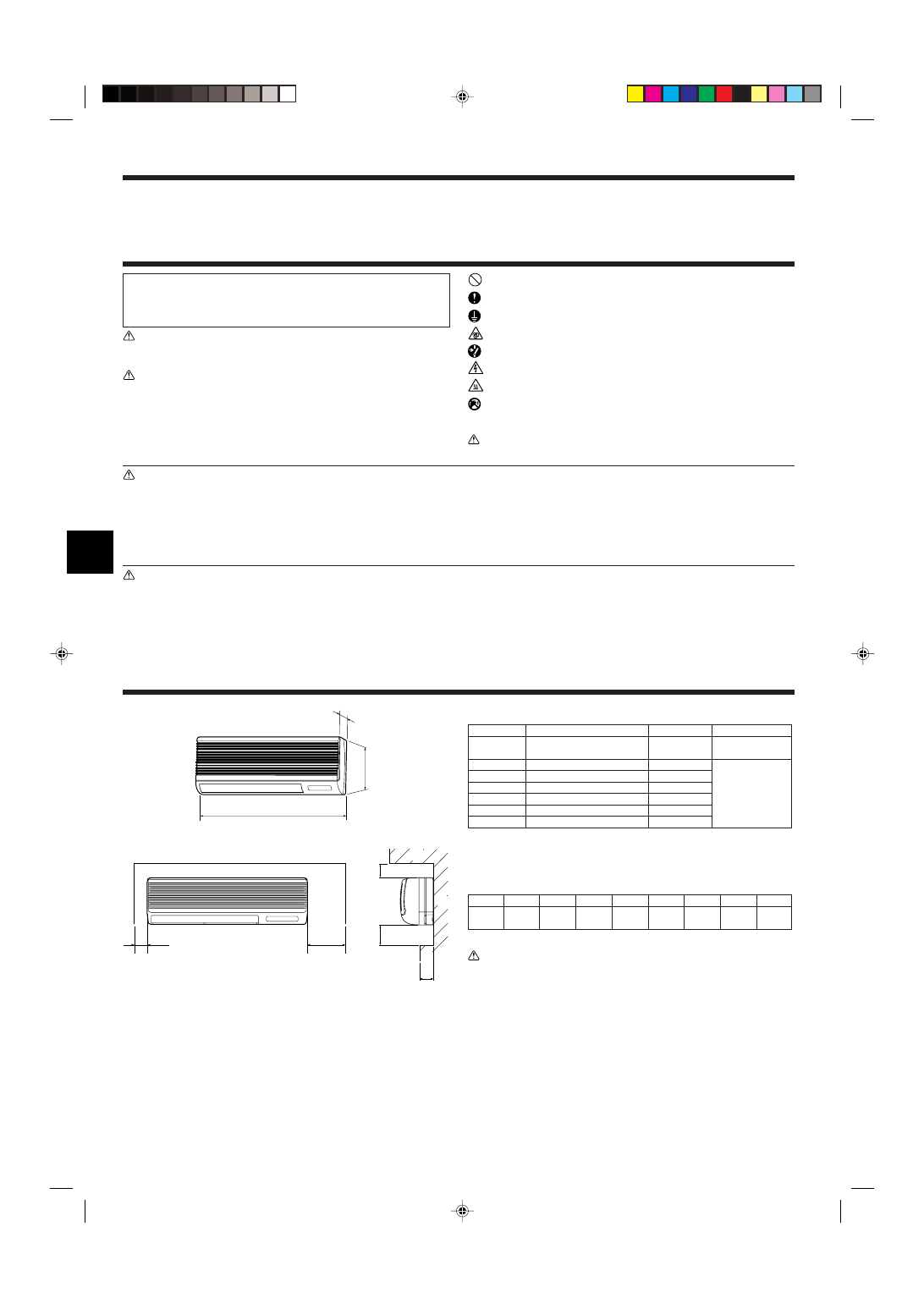
The indoor unit comes with the following parts and accessories:
PART NUMBER
ACCESSORY
QUANTITY
LOCATION OF SETTING
1
Wall-fixing bracket
1
Fix at the back of
the unit.
2
Tapping screw 4
× 35
12
3
Felt tape
3
4
Pipe cover
1
5
Band
3
6
Flare nut 3/8 F P50
1
7
Flare nut 5/8 F P50
1
2.1. Outline dimensions (Fig. 2-1)
Select a proper position allowing the following clearances for installation and mainte-
nance.
(mm)
Models
W
D
H
A
E
F
G
H
PKFY-
P·VGM
990
235
340
Min. 30 Max. 130 Min. 180 Min. 50 Min. 150
B Ceiling
C Wall
D Furnishing, etc
Warning:
Mount the indoor unit on a ceiling strong enough to withstand the weight of the
unit.
Fig. 2-1
Set in packing
material.
3
3. Installing the indoor unit
(mm)
Fig. 3-1
Fig. 3-2
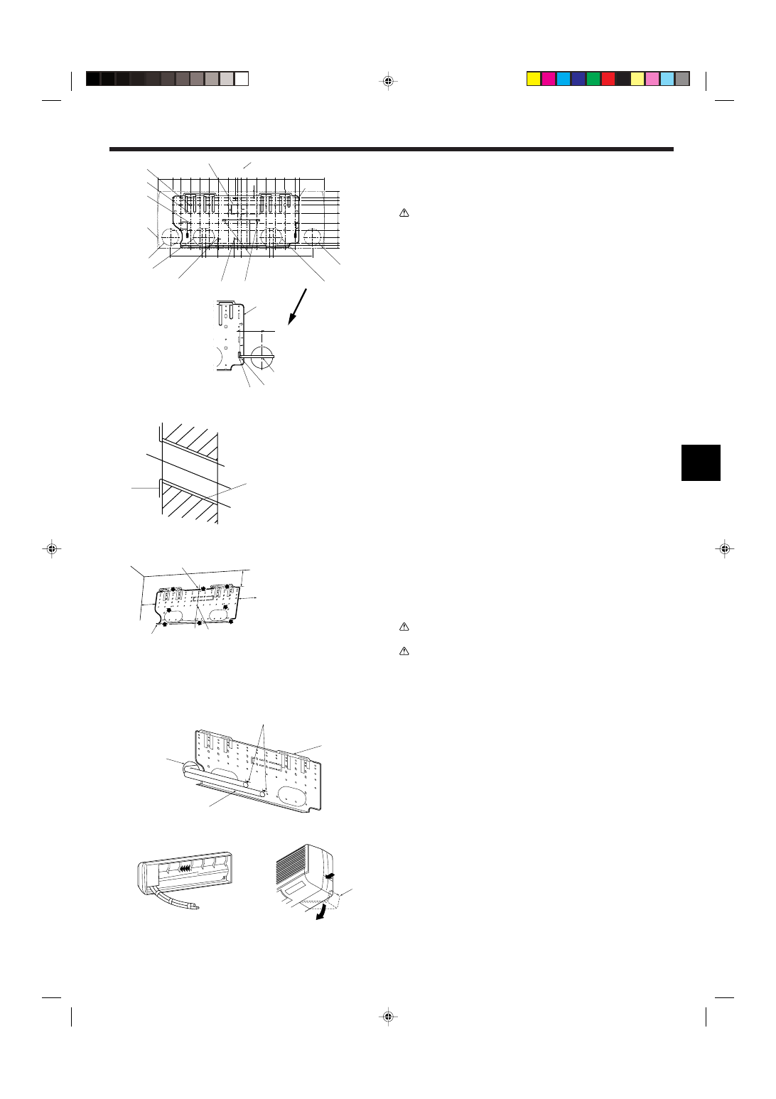
3.1. Installing the wall mounting fixture (Fig. 3-1)
3.1.1. Setting the wall mounting fixture and piping positions
s Using the wall mounting fixture, determine the unit’s installation position
and the locations of the piping holes to be drilled.
Warning:
Before drilling a hole in the wall, you must consult the building contractor.
A Supporting piece
J Bottom right pipe slot (ø90)
B Mount board
K Bottom right pipe slot knockout hole
C Main body
L Liquid pipe flare connection position
D Slot (6-11
× 20)
M Gas pipe flare connection position
E Unit center
N Level setting standard
F Bolt hole (14-ø14)
V Insert scale.
G Tapping hole (49-ø5)
Y Hole centre
H Bottom left pipe slot (ø90)
Z Align the scale with the line.
I Bottom left pipe slot knockout hole
420
495
405
360
300
245
190
135
75
32 20
0
35
25
95
205
260
320
345
495
150
230 210
140
170 190
425
40
0
0
35
55
80
130
190
230
272
310
340
322
*
A
B
C
D
E
F
G
H
I
J
K
L
M
N
B
Y
Z
V
100
A
C
D
E
B
A Sleeve
B Hole
C (Indoors)
D Wall
E (Outdoors)
3.1.2. Drilling the piping hole (Fig. 3-2)
s Use a core drill to make a hole of 90-100 mm diameter in the wall in the
piping direction, at the position shown in the diagram to the left.
s The hole should incline so that the outside opening is lower than the inside
opening.
s Insert a sleeve (with a 90 mm diameter and purchased locally) through the
hole.
Note:
The purpose of the hole’s inclination is to promote drain flow.
3.1.3. Installing the wall mounting fixture (Fig. 3-3)
s Since the indoor unit weighs near 30 kg, selection of the mounting location
requires thorough consideration. If the wall does not seem to be strong
enough, reinforce it with boards or beams before installation.
s The mounting fixture must be secured at both ends and at the centre, if
possible. Never fix it at a single spot or in any nonsymetrical way.
(If possible, secure the fixture at all the positions marked with a bold arrow.)
Warning:
If possible, secure the fixture at all positions indicated with a bold arrow.
Caution:
• The unit body must be mounted horizontally.
• Fasten at the holes marked with
▲ as shown by the arrows.
1 Fasten a thread to the hole
2 The level can be easily obtained by hanging a weight from the string and aligning the string
with the mark.
3.2. When embedding pipes into the wall (Fig. 3-4)
• The pipes are on the bottom left.
• When the cooling pipe, drain pipes internal/external connection lines etc are to be
embedded into the wall in advance, the extruding pipes etc, may have to be bent
and have their length modified to suit the unit.
• Use marking on the mount board as a reference when adjusting the length of the
embedded cooling pipe.
• During construction, give the length of the extruding pipes etc some leeway.
A Mount board
B Reference marking for flare connection
C Through hole
D On-site piping
3.3. Preparing the indoor unit
Rear, right and lower piping (Fig. 3-5)
1. Bind the cooling pipe and drain pipe together.
• Bind the pipes together with vinyl tape at three or more points. This will facilitate
passing the pipes through the wall.
2. Remove the corner box and knock out the knockout holes as necessary.
• Remove the corner box by pushing in a downward direction b, while at the same
time, pressing in the upper side part of the corner box a.
A Corner box
B Under cover
Fig. 3-3
Fig. 3-4
Fig. 3-5
1
D
2
B
A
C
A
B
D
C
a
A
b
A Min. 140 mm
B Min. 300 mm
C Min. 55 mm
D Mount board
4
a
a
A
B
b
b
Fig. 3-6
A
B
C
B
A
A
30~40
C
A
B
(mm)
Fig. 3-7
Fig. 3-8
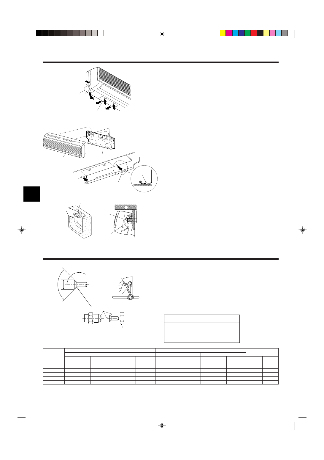
Left and left rear piping (Fig. 3-6)
1. Remove the under cover.
• Remove the under cover by sliding it towards the rear of the unit b, while at the
same time, pressing the two points marked by arrow heads a.
2. Remove the corner box and knock out the knockout holes as necessary.
3.4. Mounting the indoor unit
1. Affix the mounting plate to the wall.
2. Hang the indoor unit on the two hooks positioned on the upper part of the mount-
ing plate.
3. Installing the indoor unit
4. Refrigerant pipe
90
°
±
0.5
°
ø
A
R0.4~R0.8
A
45
°±2°
B
Fig. 4-1
4.1. Connecting pipes (Fig. 4-1)
• When commercially available copper pipes are used, wrap liquid and gas pipes
with commercially available insulation materials (heat-resistant to 100 °C or more,
thickness of 12 mm or more).
• The indoor parts of the drain pipe should be wrapped with polyethylene foam insu-
lation materials (specific gravity of 0.03, thickness of 9 mm or more).
• Apply thin layer of refrigerant oil to pipe and joint seating surface before tightening
flare nut.
• Use two wrenches to tighten piping connections.
• Use refrigerant piping insulation provided to insulate indoor unit connections. Insu-
late carefully.
Rear, right and lower piping (Fig. 3-7)
3. Affix the indoor unit.
4. After connecting the pipes, put the corner box back to where it was (follow the
removal steps backwards).
A Square hole
B Hooks
Left and left rear piping (Fig. 3-8)
3. Cut out a mounting piece from the packaging material.
4. Pull the indoor unit up towards yourself as shown in the figure below and slide the
mounting piece in to the mounting plate using the mounting piece setting marks
as reference.
5. After connecting the pipes and wiring, put the under cover back to where it was,
and remove the mounting piece and affix the indoor unit as shown in the left
figure.
6. Put the corner box back to where it was.
A Mounting piece
B Ceiling
C Rib
C
B
A Flare cutting dimensions
Copper pipe O.D.
Flare dimensions
(mm)
øA dimensions (mm)
ø6.35
8.7 - 9.1
ø9.52
12.8 - 13.2
ø12.7
16.2 - 16.6
ø15.88
19.3 - 19.7
ø19.05
22.9 - 23.3
C Apply refrigerating machine oil over the entire flare seat surface.
B Refrigerant pipe sizes & Flare nut tightening torque
* Use the provided flare nut for the following pipes: Liquid pipe of P50, P100, P125, and gas pipe of P50.
P20/25/32/40
P50
P63/80
P100/125
Flare nut O.D.
Liquid
Gas
pipe
pipe
(mm)
(mm)
17
26
22
29
22
29
22
36
R410A
Liquid pipe
Gas pipe
Tightening
Tightening
Pipe size
torque
Pipe size
torque
(mm)
(N.m)
(mm)
(N.m)
ODø6.35 (1/4”)
14 - 18
ODø12.7 (1/2”)
49 - 61
ODø6.35 (1/4”)
34 - 42
ODø12.7 (1/2”)
68 - 82
ODø9.52 (3/8”)
34 - 42
ODø15.88 (5/8”)
68 - 82
ODø9.52 (3/8”)
34 - 42
ODø15.88 (5/8”)
100 - 120
R407C or R22
Liquid pipe
Gas pipe
Tightening
Tightening
Pipe size
torque
Pipe size
torque
(mm)
(N.m)
(mm)
(N.m)
ODø6.35 (1/4”)
14 - 18
ODø12.7 (1/2”)
49 - 61
ODø9.52 (3/8”)
34 - 42*
ODø15.88 (5/8”)
68 - 82*
ODø9.52 (3/8”)
34 - 42
ODø15.88 (5/8”)
68 - 82
ODø9.52 (3/8”)
34 - 42
ODø19.05 (3/4”)
100 - 120*

5
A
E
60
10
22
70
21
245
D
8
B
E
D
10
190
22
70
35
8
60
C
E
8
60
10
22
70
21
245
D
4. Refrigerant pipe
1
Fig. 4-2
Fig. 4-4
E
D
B
C
A
C
B
D
F
35
449
581
280
31
54
86
153
700
Fig. 4-3
A
B
C
D
E
F
G
2
4.2. Positioning refrigerant and drain piping
1 Position of refrigerant and drain piping (Fig. 4-2)
• The drain pipe can be cut midway to meet the on-site conditions.
A (Total length of flexible hose)
D Drain hose
B Liquid pipe
E Left-side piping
C Gas pipe
F Right-side piping
2 Determine the position of the knockout holes on the unit body. (Fig. 4-3)
s Cut the knockout holes using a saw blade or an adequate knife.
Take care not to damage other parts of the unit.
• Remove the corner box and drill a knockout hole. If a hole is made without remov-
ing the box, the drain hose could be damaged.
A Left-side piping
D Remote controller cable through hole
B Lower piping
E Corner box
C Right-side piping
4.3. Refrigerant piping (Fig. 4-4)
Indoor unit
1. Remove the flare nut and cap of the indoor unit.
2. Make a flare for the liquid pipe and gas pipe and apply refrigerating machine oil
(available from your local supplier) to the flare sheet surface.
3. Quickly connect the on site cooling pipes to the unit.
4. Wrap the pipe cover 3 that is attached to the gas pipe and make sure that the
connection join is not visible.
5. Wrap the pipe cover of the unit’s liquid pipe and make sure that it covers the
insulation material of the on site liquid pipe.
6. Use the bands that are provided 4 to tighten both ends (15 – 20mm) of each pipe
cover 3.
A Cooling pipe and insulation (available from local supplier)
B Unit’s gas pipe
E Bands 4
C Unit’s liquid pipe
F On site gas pipe
D Pipe cover 3
G On site liquid pipe
When using commercially available copper pipes: (Fig. 4-5)
See that stop valve on outdoor unit is fully shut (unit is shipped with valve shut). After
all piping connections between indoor and outdoor unit have been completed, vacuum-
purge air from system through the service port for the stop valve on the outdoor unit.
1 Apply refrigerating machine oil all over the flare sheet.
2 Always use the flare nuts that are attached to the main unit.
A Band 4
B Tightly wrapped
C Refrigerant pipe
D Refrigerant pipe insulation
E Pipe cover 3
• To prevent Refrigerant pipes from gathering moisture, wrap the pipes that are in the
unit’s pipe storage space with the felt tape provided 5.
1
2
B
C
D
E
A
Fig. 4-5
5. Drainage piping work
Fig. 5-1
A
B
C
5.1. Drainage piping work (Fig. 5-1)
• Drain pipes should have an inclination of 1/100 or more.
• For extension of the drain pipe, use a soft hose (inner dia. 15 mm) available on the
market or hard vinyl chloride pipe (VP-20). Make sure that there is no water leak-
age from the connections.
• If the drain pipe passes indoors it must be covered with insulating material (foamed
polyethylene: specific gravity: 0.03, thickness: 9 mm or more) available on the market.
• Do not put the drain piping directly in a drainage ditch where sulphuric gas may be
generated.
• When piping has been completed, check that water flows from the end of the drain
pipe.
A Drain connection socket
C Indoor unit’s drain hose
B On site drain pipe (VP-20)
Caution:
The drain pipe should be installed according to this Installation Manual to en-
sure correct drainage. Thermal insulation of the drain pipes is necessary to
prevent condensation. If the drain pipes are not properly installed and insu-
lated, condensation may drip on the ceiling, floor or other possessions.
6
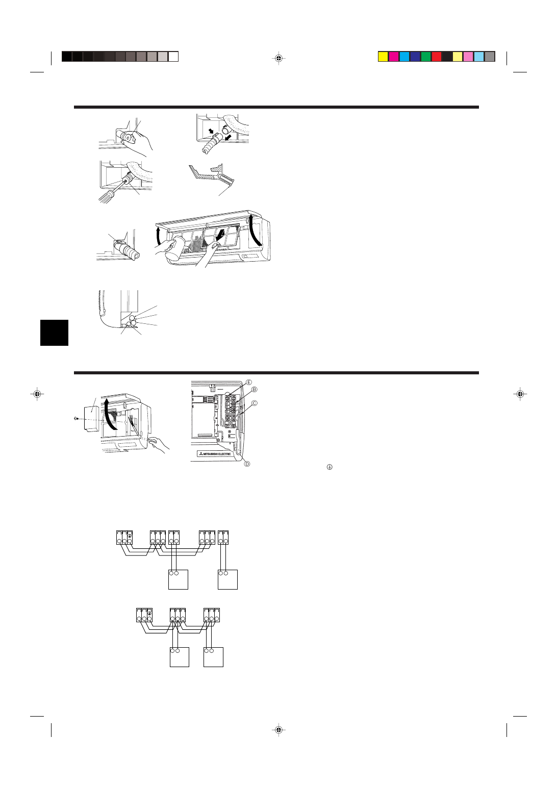
5. Drainage piping work
Preparing left and left rear piping (Fig. 5-2)
1 Remove the drain cap.
• Remove the drain cap by holding the bit that sticks out at the end of the pipe and
pulling.
A Drain cap
2 Remove the drain hose.
• Remove the drain hose by holding on to the base of the hose a (shown by arrow)
and pulling towards yourself b.
3 Insert the drain cap.
• Insert a screwdriver etc into the hole at the end of the pipe and be sure to push to
the base of the drain cap.
4 Insert the drain hose.
• Push the drain hose until it is at the base of the drain box connection outlet.
• Please make sure the drain hose hook is fastened properly over the extruding drain
box connection outlet.
B Hooks
Remove the side panel of the indoor unit on the drain side. Pour water in the drain
pan and check that it comes out the drain pipe end. After confirmation, reinstall the
side panel.
A
a
b
A
A
B
1
3
2
4
Fig. 5-2
6. Electrical work
A
Fig. 5-3
Fig. 6-1
6.1. Indoor unit (Fig. 6-1)
1. Remove the corner box.
2. Install each wire into the unit.
3. Open the front grill, remove 1 tapping screw and remove the terminal block cover.
4. Connect each wire properly to the terminal block.
• In consideration of future servicing, please leave some leeway for the wiring length.
5. Put all the parts back the way they were.
6. Use a clamp from the bottom of the electric parts box to fasten each wire.
A Terminal block cover
B Terminal block for transmission cable
Non polarized M1, M2
C Terminal block for power supply
Polarized L, N,
D Clamp to fasten wires
E MA remote controller terminals
Non polarized 1, 2
Power supply wiring
• Power supply codes of appliance shall not be lighter than design 245 IEC 53 or 227
IEC 53.
• Install an earth longer and thicker than other cables.
A means for the disconnection of the supply with an isolation switch, or similar de-
vice, in all active conductors shall be incorporated in the fixed wiring.
6.2. Connecting remote controller, indoor and outdoor
transmission cables (Fig. 6-2)
• Connect indoor unit TB5 and outdoor unit TB3. (Non-polarized 2-wire)
The “S” on indoor unit TB5 is a shielding wire connection. For specifications about
the connecting cables, refer to the outdoor unit installation manual.
• Install a remote controller following the manual supplied with the remote controller.
• Connect the remote controller’s transmission cable within 10 m using a 0.75 mm
2
core cable. If the distance is more than 10 m, use a 1.25 mm
2
junction cable.
1 MA Remote controller
• Connect the “1” and “2” on indoor unit TB15 to a MA remote controller. (Non-polar-
ized 2-wire)
• DC 9 to 13 V between 1 and 2 (MA remote controller)
2 M-NET Remote controller
• Connect the “M1” and “M2” on indoor unit TB5 to a M-NET remote controller. (Non-
polarized 2-wire)
• DC 24 to 30 V between M1 and M2 (M-NET remote controller)
A Terminal block for indoor transmission cable
B Terminal block for outdoor transmission cable
C Remote controller
Fig. 6-2
1
2
A
A
C
TB5
TB15 TB5
TB15
S
M1 M2
S
M1 M2
B
TB3
M1 M2
2
1
C
2
1
A
A
C
TB5
TB5
S
M1 M2
S
M1 M2
C
B
TB3
M1 M2
C
B
C
D
A
A Gas pipe
B Liquid pipe
C Felt tape 3
D Drain hose
5.2. Completing the piping (Fig. 5-3)
Using the unit’s pipe storage space (for left and left rear piping)
• To prevent cooling pipes from gathering moisture, wrap the pipes that are in the
unit’s pipe storage space with the felt tape provided 3.
• When wrapping with the felt tape, be sure to double over by no more than half the
width of the tape.
• Use a bandage clip etc to fasten the end to the felt tape.
7
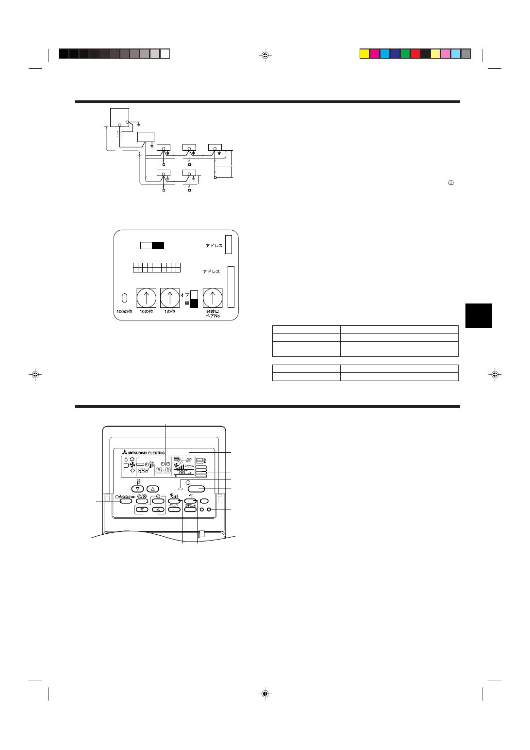
6. Electrical work
Constraints on transmission cable (Fig. 6-3)
Longest wiring length (L
1
+L
2
+L
4
or L
1
+L
3
or L
2
+L
3
+L
4
): less than 200 m
Length between indoor unit and remote controller (
R): within 10 m
G Outdoor unit
H Earth
I BC controller
J Indoor unit
K M-NET Remote controller
L Non-polarized 2-wire
Note:
*1 Put the transmission cable earth via the outdoor unit’s earth terminal
to
the ground.
*2 If the remote controller cable exceeds 10 m, use a 1.25 mm
2
diameter cable
over the exceeded portion, and add that exceeded portion to within 200 m.
*3 The BC controller is required only for simultaneous cooling and heating
series R2.
6.3. Setting addresses (Fig. 6-4)
(Be sure to operate with the main power turned OFF.)
• There are two types of rotary switch setting available: setting addresses 1 to 9 and
over 10, and setting branch numbers.
Note:
Please set the switch SW5 according to the power supply voltage.
• Set SW5 to 240 V side when the power supply is 230 and 240 volts.
• When the power supply is 220 volts, set SW5 to 220 V side.
A Address board
6.4. Types of control cables
1. Wiring transmission cables: Shielding wire CVVS or CPEVS
• Cable diameter: More than 1.25 mm
2
2. M-NET Remote control cables
Kind of remote control cable Shielding wire MVVS
Cable diameter
More than 0.5 to 1.25 mm
2
Remarks
When 10 m is exceeded, use cable with the same
specifications as transmission line wiring.
3. MA Remote control cables
Kind of remote control cable 2-core cable (unshielded)
Cable diameter
0.3 to 1.25 mm
2
Fig. 6-3
A
Fig. 6-4
7. Test run (Fig. 7-1)
TIMER SET
PAR-20MAA
ON/OFF
CENTRALLY CONTROLLED
ERROR CODE
CLOCK
ON
OFF
˚C
CHECK
CHECK MODE
FILTER
TEST RUN
FUNCTION
˚C
1Hr.
NOT AVAILABLE
STAND BY
DEFROST
FILTER
CHECK TEST
TEMP.
2
BC
3
4
5
1
A
E
D
G
I
J
J
J
K
K
K
K
J
J
L
K
H
*1
*3
L1
L2
L4
r
L3
*2
1 Press [TEST RUN] button twice
→ displaying [TEST RUN] on the screen.
2 Press [Selecting operation] button.
→ Check that wind is blowing out.
3 Press [Fan speed adjustment] button.
→ Check that the wind speed is changed.
4 Press [Up/down airflow selection] button to change wind direction.
5 Press [ON/OFF] button to clear test run
. → Test run stops.
A Lighting in operation
B Displaying inspection code
C Displaying remaining test run time
D Displaying indoor unit’s liquid pipe temperature
E Displaying test run
Note:
• The 2-hour-set timer is activated to automatically stop test run after two hours.
• The remote controller displays the temperature of the indoor unit’s liquid
pipe on the temperature display section during test run.
Fig. 7-1
SW14
0
SW11
0
SW12
0
1 2 3 4 5 6 7 8 9 10
ON
OFF
SW1
SW5
220V
240V
SWC
CN82
CN43
Please be sure to put the contact address/telephone number on
this manual before handing it to the customer.
• Low Voltage Directive 73/23/ EEC
• Electromagnetic Compatibility Directive 89/
336/ EEC
This product is designed and intended for use in the residential,
commercial and light-industrial environment.
HEAD OFFICE: MITSUBISHI DENKI BLDG., 2-2-3, MARUNOUCHI, CHIYODA-KU, TOKYO 100-8310, JAPAN
Printed in Japan
BG79U323H02
The product at hand is
based on the following
EU regulations:
Wyszukiwarka
Podobne podstrony:
IM PCA RP2 6GA BG79U334H01 Aug 2004
IM PKFY P63 100VFM E BG79U776H01 GB 2006
IM PKFY P32 50VHM E RG79D439H03 Aug 2009
IM PKFY P20 25VBM E RG79D177H01 GB 2007
IM PMFY P VBM E BG79U328H02 08 2004
IM PCFY P40 125VKM E RG79D452H01 GB 01 2009
IM PEFY P15 63VMS1 L E KB79H130H03 GB 08 2009
IM PAC IF011B E IF012B E BH79D099H02 GB 09 2009
IM CMY R100 200VBK WT05221X02 GB Dec 2008
IM MSZ FD25 35VA SG79Y970H07 GB 2007
IM PEFY P40 250VMH E WT04198X02 GB 2005
IM MSZ GA50 71VA SG79Y434H01 GB 07 2005
IM MXZ 2A30 52VA SG79Y760H04 GB 04 2009
IM MS MSH GD80VB JG79A087H01 GB 04 2008
IM PFFY P20 63VLRMM E WT05228X01 GB 2007
IM PUHZ RP200 250YHA BG79U637H03 GB 03 2007
więcej podobnych podstron