English
Deutsch
Français
Nederlands
Español
Italiano
∂ÏÏËÓÈο
Português
Türkçe
Русский
INSTALLATION MANUAL
For safe and correct use, please read this installation manual thoroughly before installing the air-conditioner
unit.
INSTALLATIONSHANDBUCH
Zum sicheren und ordnungsgemäßen Gebrauch der Klimaanlage das Installationshandbuch gründlich
durchlesen.
MANUEL D’INSTALLATION
Veuillez lire le manuel d’installation en entier avant d’installer ce climatiseur pour éviter tout accident et vous
assurer d’une utilisation correcte.
INSTALLATIEHANDLEIDING
Voor een veilig en juist gebruik moet u deze installatiehandleiding grondig doorlezen voordat u de airconditioner
installeert.
MANUALE DI INSTALLAZIONE
Per un uso sicuro e corretto, leggere attentamente questo manuale di installazione prima di installare il condizionatore
d’aria.
MANUAL DE INSTALACIÓN
Para un uso seguro y correcto, lea detalladamente este manual de instalación antes de montar la unidad de
aire acondicionado.
E°XEIPI¢IO O¢H°IøN E°KATA™TA™H™
°È· ·ÛÊ¿ÏÂÈ· Î·È ÛˆÛÙ‹ ¯Ú‹ÛË, ·Ú·Î·Ï›ÛÙ ‰È·‚¿ÛÂÙ ÚÔÛ¯ÙÈο ·˘Ùfi ÙÔ ÂÁ¯ÂÈÚ›‰ÈÔ ÂÁηٿÛÙ·Û˘
ÚÈÓ ·Ú¯›ÛÂÙ ÙËÓ ÂÁηٿÛÙ·ÛË Ù˘ ÌÔÓ¿‰·˜ ÎÏÈÌ·ÙÈÛÌÔ‡.
MANUAL DE INSTALAÇÃO
Para segurança e utilização correctas, leia atentamente este manual de instalação antes de instalar a unidade
de ar condicionado.
MONTAJ ELK‹TABI
Emniyetli ve do¤ru biçimde nas›l kullan›laca¤›n› ö¤renmek için lütfen klima cihaz›n› monte etmeden önce bu
elkitab›n› dikkatle okuyunuz.
РУКОВОДСТВО ПО УСТАНОВКЕ
Для осторожного и правильного использования прибора необходимо тщательно ознакомиться с данным
руководством по установке до выполнения установки кондиционера.
FOR INSTALLER
FÜR INSTALLATEURE
POUR L’INSTALLATEUR
VOOR DE INSTALLATEUR
PER L’INSTALLATORE
PARA EL INSTALADOR
PARA O INSTALADOR
°π∞ ∞À∆√¡ ¶√À ∫∞¡∂π ∆∏¡ ∂°∫∞∆∞™∆∞™∏
MONTÖR ‹Ç‹N
ДЛЯ УСТАНОВИТЕЛЯ
Air-Conditioners For Building Application
INDOOR UNIT
PMFY-P·VBM-E
For use with the R410A, R407C & R22
Bei Verwendung von R410A, R407C & R22
A utiliser avec le R410A, R407C et le R22
Bij gebruik van R410A, R407C & R22
Para utilizar con el R410A, R407C y el R22
Uso del refrigerante R410A, R407C e R22
°È· ¯Ú‹ÛË ÌÂ Ù·
R410A, R407C Î·È R22
Para utilizaçao com o R410A, R407C e o R22
R410A, R407C ve R22 ile beraber kullanmak için
Для использования с моделями R410A, R407С и R22

2
s Before installing the unit, make sure you read all the “Safety precau-
tions”.
s Please report to your supply authority or obtain their consent before
connecting this equipment to the power supply system.
Warning:
Describes precautions that must be observed to prevent danger of injury or
death to the user.
Caution:
Describes precautions that must be observed to prevent damage to the unit.
After installation work has been completed, explain the “Safety Precautions,” use,
and maintenance of the unit to the customer according to the information in the Op-
eration Manual and perform the test run to ensure normal operation. Both the Instal-
lation Manual and Operation Manual must be given to the user for keeping. These
manuals must be passed on to subsequent users.
2. Installing the indoor unit
Contents
Warning:
• Ask the dealer or an authorized technician to install the air conditioner.
• Install the unit at a place that can withstand its weight.
• Use the specified cables for wiring.
• Use only accessories authorized by Mitsubishi Electric and ask the dealer or
an authorized technician to install them.
• Do not touch the heat exchanger fins.
• Install the air conditioner according to this Installation Manual.
• Have all electric work done by a licensed electrician according to local regu-
lations.
• If the air conditioner is installed in a small room, measures must be taken to
prevent the refrigerant concentration from exceeding the safety limit even if
the refrigerant should leak.
• The cut face punched parts may cause injury by cut, etc. The installers are
requested to wear protective equipement such as gloves, etc.
1. Safety precautions ................................................................................... 2
2. Installing the indoor unit ........................................................................... 2
3. Refrigerant pipe and drain pipe ............................................................... 4
4. Electrical work .......................................................................................... 6
5. Installing the grille .................................................................................... 7
6. Test run (Fig. 6-1) ..................................................................................... 9
1. Safety precautions
: Indicates an action that must be avoided.
: Indicates that important instructions must be followed.
: Indicates a part which must be grounded.
: Indicates that caution should be taken with rotating parts.
: Indicates that the main switch must be turned off before servicing.
: Beware of electric shock.
: Beware of hot surface.
ELV
: At servicing, please shut down the power supply for both the Indoor and
Outdoor Unit.
Warning:
Carefully read the labels affixed to the main unit.
Caution:
• Do not use the existing refrigerant piping, when use R410A or R407C refrig-
erant.
• Use ester oil, either oil or alkylbenzene (small amount) as the refrigerator oil
to coat flares and flange connections, when use R410A or R407C refrigerant.
• Do not use the air conditioner where food, pets, plants, precision instruments,
or artwork are kept.
• Do not use the air conditioner in special environments.
• Ground the unit.
• Install an leak circuit breaker, as required.
• Use power line cables of sufficient current carrying capacity and rating.
• Use only a circuit breaker and fuse of the specified capacity.
• Do not touch the switches with wet fingers.
• Do not touch the refrigerant pipes during and immediately after operation.
• Do not operate the air conditioner with the panels and guards removed.
• Do not turn off the power immediately after stopping operation.
Fig. 2-1
1
2
3
4
5
2.1. Check the indoor unit accessories (Fig. 2-1)
The indoor unit should be supplied with the following spare parts and accessories
(contained in the inside of the intake grille).
Accessory name
Q’ty
1
Washer
4 pcs
2
Washer (with insulation)
4 pcs
3
Pipe cover
2 pcs
4
Band
4 pcs
5
Screw
4 pcs M5 × 0.8 × 30
3
2. Installing the indoor unit
C
A
D
A
B
1
10
230
E
F
230
Fig. 2-2
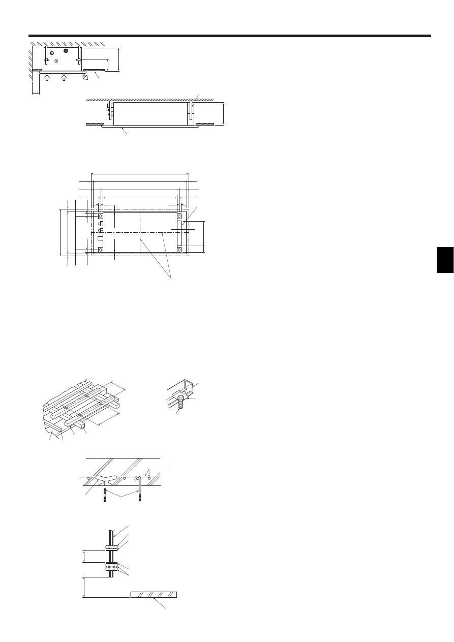
2.2. Service space (Fig. 2-2)
• The dimensions of ceiling opening can be regulated within the range shown in
following diagram; so center the main unit against the opening of ceiling, ensuring
that the respective opposite sides on all sides of the clearance between them be-
comes identical.
A Air intake
B Air outlet
C Ceiling panel
D Min. 200 mm
E Suspension bolts W3/8 or M10
F Grille
2.3. Ceiling openings and suspension bolt installation
locations (Fig. 2-3)
• Make an opening in the ceiling 430 mm × 960 mm in size. This functions as a check
window and will be needed later during servicing.
• If the dimensions are not accurate, when the grille is installed there may be gaps
between it and the indoor unit. This may result in dripping water or other problems.
• When deciding on placement, consider carefully the space around the ceiling and
make your measurements generous.
• Ceiling types and building construction differ. Therefore you should consult with the
builder and decorator.
A The centers of the ceiling opening and the indoor unit should be aligned.
1 Outer side of grille
2 Ceiling opening
3 Bolt pitch
4 Electric box
• Using the installation template (top of the package) and the gauge (supplied as an
accessory with the grille), make an opening in the ceiling so that the main unit can
be installed as shown in the diagram. (The method for using the template and the
gauge are shown.)
• Use M10 (3/8") suspension bolts.
* Suspension bolts are to be procured at the field.
• After suspending the indoor unit, you will have to connect the pipes and wiring
above the ceiling. Once the location has been fixed and the direction of the pipes
has been determined, place the refrigerant and drainage pipes, the wiring for the
remote controller, and the wiring that connects the indoor and outdoor units in their
desired locations before suspending the indoor unit. This is especially important in
cases where the ceiling is already in existence.
1 Wooden structures (Fig. 2-4)
• Use tie beams (single storied houses) or second floor beams (two story houses) as
reinforcing members.
• Wooden beams for suspending air conditioners must be sturdy and their sides
must be at least 6 cm long if the beams are separated by not more than 90 cm and
their sides must be at least 9 cm long if the beams are separated by as much as
180 cm. The size of the suspension bolts should be ø10 mm (3/8"). (The bolts do
not come with the unit.)
• Use channel, duct and other parts procured locally to suspend the indoor unit.
2 Ferro-concrete structures (Fig. 2-5)
Secure the suspension bolts using the method shown, or use steel or wooden hang-
ers, etc. to install the suspension bolts.
A
247
69
53
17.5
17.5
20
20
28
28
45
20
45
20
340
3
430
2
470
1
26
74.5
20
26
74.5
20
759
811
3
960
2
1000
1
4
Fig. 2-3
(mm)
I Suspension bolts M10 (3/8") (procure lo-
cally)
J Steel reinforcing rod
K C channel
L Channel suspension bracket
M M10 suspension bolt
D Ceiling panel
E Rafter
F Beam
G Roof beam
H Use inserts rated at 100-150 kg each (pro-
cure locally)
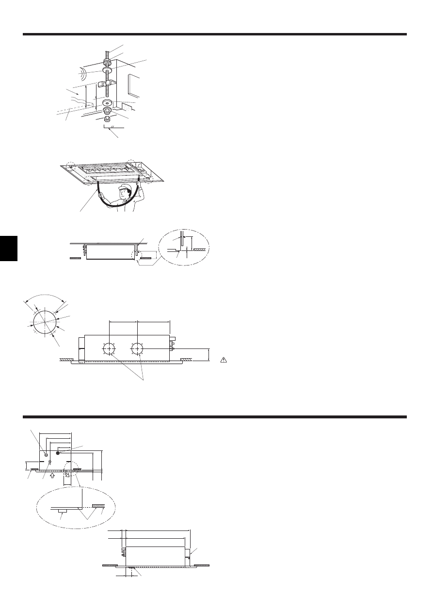
2.4. Unit suspension procedures (Fig. 2-6)
Procure 3/8" bolts or M10 bolts locally.
• Adjust the length of the bolt’s protrusion from the ceiling surface beforehand.
*1. When using an extra upper nut in suspending the unit, in some cases you may
have to add it later.
A Suspension bolt
B Ceiling panel
C Nut
D Washer (with insulation) 2
E Washer (without insulation) 1
A
C
D
E
C
*1
B
Min. 20
Min. 30
(mm)
D
E
F G
340
811
K
L
M
J
H
I
Fig. 2-4
Fig. 2-6
Fig. 2-5
(mm)
(mm)
4
2. Installing the indoor unit
Fig. 2-7
(mm)
F
G
B
B
C
*
E
*
D
C
A
1
12
Min. 20
1. 2. 3.
Check the pitch of the suspension bolt. (340 mm × 811 mm)
1. Thread washers 1 2 (supplied) and their nuts (procured locally) onto the sus-
pension bolt in advance. (Fig. 2-7)
* Do this in the following order (from the top): nut, insulated washer 2, washer
without insulation 1, two nuts.
* Position insulated washer 2 with the insulated surface pointing down, as in the
figure.
2. Lift the unit into place, aligned properly with the suspension bolt. Pass the bracket
between washers 1 and 2, which are already in place, and secure it. Do the
same in all four places.
* Make sure the suspension bolt extends 20 mm or more from the surface of the
ceiling. Otherwise you will not be able to install the cover panel (sold separately).
3. If the long opening in the bracket and opening in the ceiling do not align, adjust
them until they do.
A Suspension bolt (3/8" or M10)
B Ceiling surface
C Nut (3/8" or M10)
D Washer 2 (with insulation)
E Washer 1
F (Install with insulation facing down)
G Measurement to upper face of bracket
4. Check that the four corners are all level, using a spirit level or clear plastic tubing
with water in it. (Fig. 2-8)
* Make sure that any slant in the unit after installation is less than 0.5 degrees
(approx. 6 mm on the long dimension of the unit).
5. Tighten all the nuts. (Fig. 2-9)
A Suspension bolt (3/8" or M10)
B Clear plastic tubing
C Underside of bracket
D Secure front panel here
E Make these surfaces are flush with each other (0 - 3 mm)
2.5. Fresh air intake hole (Fig. 2-10)
At the time of installation, use the hole (knock out) located at the positions shown in
following diagram, as and when required.
A Fresh air intake hole (Knock out)
B 4-ø2.8 burring hole
Note:
Make sure that the fresh air intake is no more than 20% of the entire air intake
(when the air flow speed is set to its highest setting).
Caution:
Linkage of duct fan and air conditioner.
If a duct fan is used, be sure to link it with the air conditioner when outside air
is taken in.
Do not run just the duct fan. Otherwise, condensation may form.
B
1
10
1
10
A
C
D E
4.
5.
Fig. 2-8
Fig. 2-9
ø
100
ø
122
90°
B
A
A
250
288.5
108
Fig. 2-10
(mm)
3. Refrigerant pipe and drain pipe
E
D
F
(56)
759
43
C
812
46
A
D
C
ø12.7
198
230
(10)
(96)
(20)
96
ø6.35
B
141
254
302
395
F
G
B
Fig. 3-1
3.1. Refrigerant and drainage piping locations
A Drain pipe (Use PVC pipe O.D. ø26)
B Ceiling panel (underside)
C Refrigerant pipe (gas)
D Refrigerant pipe (liquid)
E Electrical box
F Drain pan
G Make sure these surfaces are flush with each other.
(mm)
(mm)
5
3. Refrigerant pipe and drain pipe
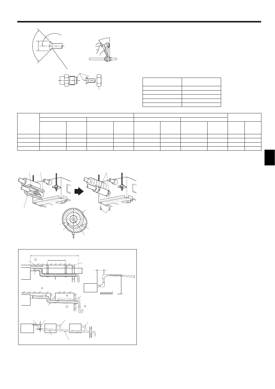
3.2. Connecting pipes (Fig. 3-2)
• When commercially available copper pipes are used, wrap liquid and gas pipes
with commercially available insulation materials (heat-resistant to 100 °C or more,
thickness of 12 mm or more).
• The indoor parts of the drain pipe should be wrapped with polyethylene foam insu-
lation materials (specific gravity of 0.03, thickness of 9 mm or more).
• Apply thin layer of refrigerant oil to pipe and joint seating surface before tightening
flare nut.
• Use two wrenches to tighten piping connections.
• Use refrigerant piping insulation provided to insulate indoor unit connections. Insu-
late carefully.
90
°
±0.5
°
ø
A
R0.4~R0.8
A
45°±2°
B
C
B
Fig. 3-2
Installing procedures (Fig. 3-3)
1. Remove the flare nuts and caps from the indoor unit.
2. Flare-cut the liquid and gas pipes then apply refrigerating machine oil (to be lo-
cally procured) over the flare-cut seat surface.
3. Quickly connect the refrigerant piping.
∗
Remember to tighten the flare nuts with a double spanner.
4. Slide the supplied pipe cover 3 over the gas piping until it is pressed against the
sheet metal inside the unit.
5. Slide the provided pipe cover 3 over the liquid piping until it is pressed against
the sheet metal inside the unit.
6. Tighten the pipe cover 3 at the both ends (15 - 20 mm) with the supplied bands
4.
A Gas piping
E Turn the seam upward.
B Liquid piping
F Press the pipe cover against the sheet metal.
C Band 4
G Refrigerant piping heat insulating material
D Pipe cover 3
H Wrap tightly
I Cut off excess length of band.
C
H
A·B
G
D
F
E
D
C
I
Fig. 3-3
3.3. Drainage piping work (Fig. 3-4)
• Use O. D. ø26 mm PVC TUBE for drain piping and provide 1/100 or more down-
ward slope.
• Be sure to connect the piping joints using adhesive of polyvinyl chloride family.
• Observe the figure for piping work.
• Use attached drain hose to change the pipe extraction direction.
1 Correct piping
2 Wrong piping
A Insulation (9 mm or more)
B Downward slope (1/100 or more)
C Support metal
K Air bleeder
L Raised
M Odor trap
N Make as little as possible
O Make as great as possible (approx. 10 cm)
Grouped piping
D VP-20 (O. D. ø26 PVC TUBE)
E Make it as large as possible
F Indoor unit
G Make the piping size large for grouped pip-
ing.
H Downward slope (1/100 or more)
I O. D. ø38 PVC TUBE for grouped piping.
(9 mm or more insulation)
J Up to 50 cm
B
M
L
K
D
E
D
H
I
G
D
F
F
F
Max. 15cm
J
F
Fig. 3-4
Max. 20m
0.75–1.5m
N
O
A
B
C
A Flare cutting dimensions
Copper pipe O.D.
Flare dimensions
(mm)
øA dimensions (mm)
ø6.35
8.7 - 9.1
ø9.52
12.8 - 13.2
ø12.7
16.2 - 16.6
ø15.88
19.3 - 19.7
ø19.05
22.9 - 23.3
C Apply refrigerating machine oil over the entire flare seat surface.
B Refrigerant pipe sizes & Flare nut tightening torque
* Use the provided flare nut for the following pipes: Liquid pipe of P50, P100 P125, and gas pipe of P50.
1
2
P20/25/32/40
P50
P63/80
P100/125
Flare nut O.D.
Liquid
Gas
pipe
pipe
(mm)
(mm)
17
26
22
29
22
29
22
36
R410A
Liquid pipe
Gas pipe
Tightening
Tightening
Pipe size
torque
Pipe size
torque
(mm)
(N.m)
(mm)
(N.m)
ODø6.35 (1/4”)
14 - 18
ODø12.7 (1/2”)
49 - 61
ODø6.35 (1/4”)
34 - 42
ODø12.7 (1/2”)
68 - 82
ODø9.52 (3/8”)
34 - 42
ODø15.88 (5/8”)
68 - 82
ODø9.52 (3/8”)
34 - 42
ODø15.88 (5/8”)
100 - 120
R407C or R22
Liquid pipe
Gas pipe
Tightening
Tightening
Pipe size
torque
Pipe size
torque
(mm)
(N.m)
(mm)
(N.m)
ODø6.35 (1/4”)
14 - 18
ODø12.7 (1/2”)
49 - 61
ODø9.52 (3/8”)
34 - 42*
ODø15.88 (5/8”)
68 - 82*
ODø9.52 (3/8”)
34 - 42
ODø15.88 (5/8”)
68 - 82
ODø9.52 (3/8”)
34 - 42
ODø19.05 (3/4”)
100 - 120*

6
3. Refrigerant pipe and drain pipe
4. Electrical work
Fig. 3-6
Fig. 4-1
4.1. Electric wiring (Fig. 4-1)
* Make sure all electrical wiring is complete before installing the cover panel.
1. Remove the cover from the address board (two bolts).
2. Remove the cover from the electrical box (one bolt).
3. Remove the bolts securing the electrical box and lower the box (two bolts).
4. Insert the wires into the electrical box.
5. Connect the wires securely to the terminal block.
* Be sure to make the various wires long enough so the box may be lowered from
the unit during servicing.
6. Secure the wires with the wiring clamp on the side of the electrical box.
7. Replace the parts you have removed to their original locations.
A means for the disconnection of the supply with an isolation switch, or similar de-
vice, in all active conductors shall be incorporated in the fixed wiring.
Power supply wiring
• Power supply codes of appliance shall not be lighter than design 245 IEC 53 or 227
IEC 53.
• A switch with at least 3 mm contact separation in each pole shall be provided by the
air conditioner installation.
Power cable size: more than 1.5 mm
2
• Install an earth longer and thicker than other cables.
4.2. Connecting remote controller, indoor and outdoor
transmission cables (Fig. 4-2)
• Connect indoor unit TB5 and outdoor unit TB3. (Non-polarized 2-wire)
The “S” on indoor unit TB5 is a shielding wire connection. For specifications about
the connecting cables, refer to the outdoor unit installation manual.
• Install a remote controller following the manual supplied with the remote controller.
• Connect the remote controller’s transmission cable within 10 m using a 0.75 mm
2
core cable. If the distance is more than 10 m, use a 1.25 mm
2
junction cable.
1 MA Remote controller
• Connect the “1” and “2” on indoor unit TB15 to a MA remote controller. (Non-polar-
ized 2-wire)
• DC 9 to 13 V between 1 and 2 (MA remote controller)
2 M-NET Remote controller
• Connect the “M1” and “M2” on indoor unit TB5 to a M-NET remote controller. (Non-
polarized 2-wire)
• DC 24 to 30 V between M1 and M2 (M-NET remote controller)
A Terminal block for indoor transmission cable
B Terminal block for outdoor transmission cable
C Remote controller
Fig. 4-2
1
2
A
A
C
TB5
TB15 TB5
TB15
S
M1 M2
S
M1 M2
B
TB3
M1 M2
2
1
C
2
1
A
A
C
TB5
TB5
S
M1 M2
S
M1 M2
C
B
TB3
M1 M2
In cases of upward drainage (Fig. 3-5)
• The largest dimension possible for the vertical section at B is 60 cm from the
lower surface of the ceiling. Make this vertical section as short as possible.
Water drainage check (Fig. 3-6)
1. Fill the drainage pan with about 0.5 liters of water. (Don’t pour water directly into
the drain pump.)
2. Make a test run of the unit (in Cooling mode).
3. Check for water drainage at the transparent check window and the outlet of the
drainage pipe.
4. Stop the test run. (Don’t forget to turn off the power.)
A Ceiling panel
B Max. 60 cm
C Position of drain outlet
D Make as short as possible (Max. 15 cm)
E Make as small as possible
F Downward slope (1/100 or more)
G Make as great as possible (Min. 10 cm)
H Drainage pipe vertical section
I Water bottle (procure locally)
H
A
C
D
G
F
E
B
I
Fig. 3-5
A
B
F
A Cover
B Electrical box
C Terminal block for power supply
D Terminal block for transmission cable
E Control board
F Address board
G Secure with the wiring clamp
H Terminal block for MA Remote controller
C
D
G
E
F
H

7
4. Electrical work
Constraints on transmission cable (Fig. 4-3)
Longest wiring length (L
1
+L
2
+L
4
or L
1
+L
3
or L
2
+L
3
+L
4
): less than 200 m
Length between indoor unit and remote controller (R): within 10 m
G Outdoor unit
H Earth
I BC controller
J Indoor unit
K M-NET Remote controller
L Non-polarized 2-wire
Note:
*1 Put the transmission cable earth via the outdoor unit’s earth terminal to
the ground.
*2 If the remote controller cable exceeds 10 m, use a 1.25 mm
2
diameter cable
over the exceeded portion, and add that exceeded portion to within 200 m.
*3 The BC controller is required only for simultaneous cooling and heating
series R2.
4.3. Setting addresses (Fig. 4-4)
(Be sure to operate with the main power turned OFF.)
• There are two types of rotary switch setting available: setting addresses 1 to 9 and
over 10, and setting branch numbers.
Note:
Please set the switch SW5 according to the power supply voltage.
• Set SW5 to 240 V side when the power supply is 230 and 240 volts.
• When the power supply is 220 volts, set SW5 to 220 V side.
A Address board
4.4. Types of control cables
1. Wiring transmission cables: Shielding wire CVVS or CPEVS
• Cable diameter: More than 1.25 mm
2
2. M-NET Remote control cables
Kind of remote control cable Shielding wire MVVS
Cable diameter
More than 0.5 to 1.25 mm
2
Remarks
When 10 m is exceeded, use cable with the same
specifications as transmission line wiring
3. MA Remote control cables
Kind of remote control cable 2-core cable (unshielded)
Cable diameter
0.3 to 1.25 mm
2
Fig. 4-3
SW14
0
SW11
0
SW12
0
1 2 3 4 5 6 7 8 9 10
ON
OFF
SW1
SW5
220V
240V
SWC
CN82
CN43
A
Fig. 4-4
G
I
J
J
J
K
K
K
K
J
J
L
K
H
*1
*3
L1
L2
L4
r
L3
*2
1
2
3
5. Installing the grille
5.1. Checking the contents (Fig. 5-1)
• This kit contains the following parts.
Accessory name
Q’ty
Remark
1
Grille
1
2
Screw
6
M5 × 0.8 × 16
3
Screw
1
4 × 16
A Points for securing the grille
B Points for securing the grille
C Indoor unit
D Ceiling surface
E Drainage pan
F Places for securing front grille
G Make sure these surfaces are flush with each
other (0-3 mm).
Fig. 5-2
Fig. 5-1
Fig. 5-3
A
B
C
F
G
E
D
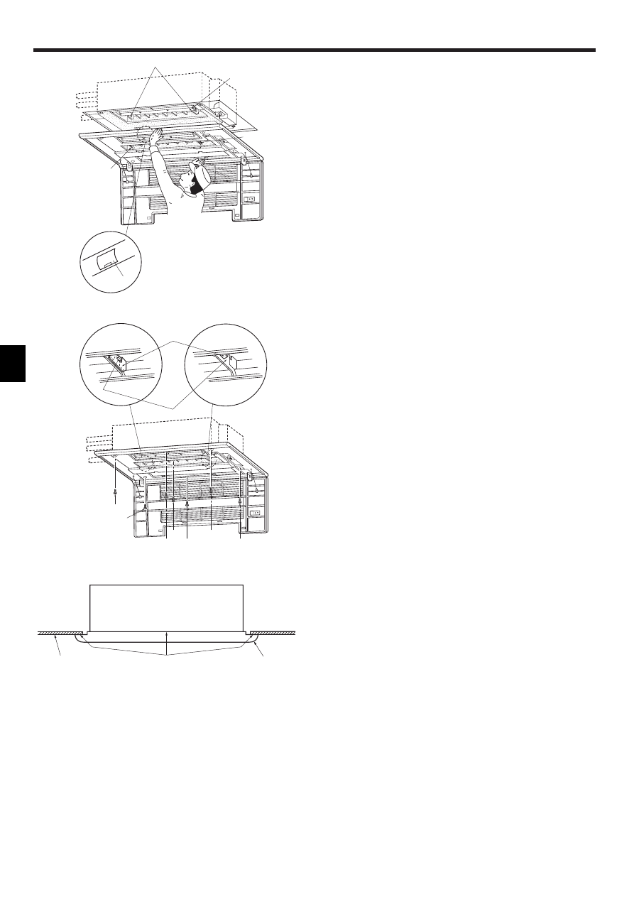
5.2. Checks before setting in place (Fig. 5-2, 3)
• Before installing the front panel, make sure the indoor unit is square with the ceiling
opening (or parallel to the angle between the wall and the ceiling).
• Check that the four points where the front panel will be secured are in contact with
the ceiling surface.
• Check that the insulation for the refrigerant pipes, drainage pipes, etc. is in place
and that wiring connections and arrangements are complete.
8
5. Installing the grille
A
B
C
D
E
Fig. 5-4
5.3. Installing the grille (Fig. 5-4)
• Open the intake grille by pressing on the place marked Push, and remove the air
filter.
• Remove the screw cover in the middle of the blower.
• Open the upper and lower flaps on the indoor unit completely.
• Hook the temporary holding tabs on the front panel to the hooks on the indoor unit.
A Hooks
B Open the upper and lower flaps completely
C Temporary holding tab
D Temporary holding tab
E Screw cover
• Adjust the front panel so that it fits properly in the angle between the ceiling and the
wall, and install the securing bolts 2 (supplied with this grille) in their four places at
left and right, leaving them slightly loose. (Fig. 5-5)
• Next tighten the securing bolts 2 and securing screws 3 in the center three places.
• Finally tighten the securing bolts 2 in the four places at left and right.
• At this point, make sure there are no gaps between the indoor unit and the front
panel, and between the front panel and the ceiling surface. If there are gaps, the
wind may come in and it may cause water to drip (Fig. 5-6).
* Tighten the securing bolts 2 and securing screws 3 completely.
• Replace the air filter and screw cover, and press the intake grille on the place
marked Push until you hear it snap into place.
A Hook
D Temporary securing tabs
B
A
D
C
2
2
3
2
2
2
2
A
D
5.4. Checks after installing
• Check that there are no gaps between the indoor unit and the front panel, and
between the front panel and the ceiling surface. If there are gaps, the wind may
come in and condensation may result.
• Check that the air filter is in place.
A Ceiling surface
B Indoor unit
C Grille
D No gaps here
Fig. 5-5
Fig. 5-6
9
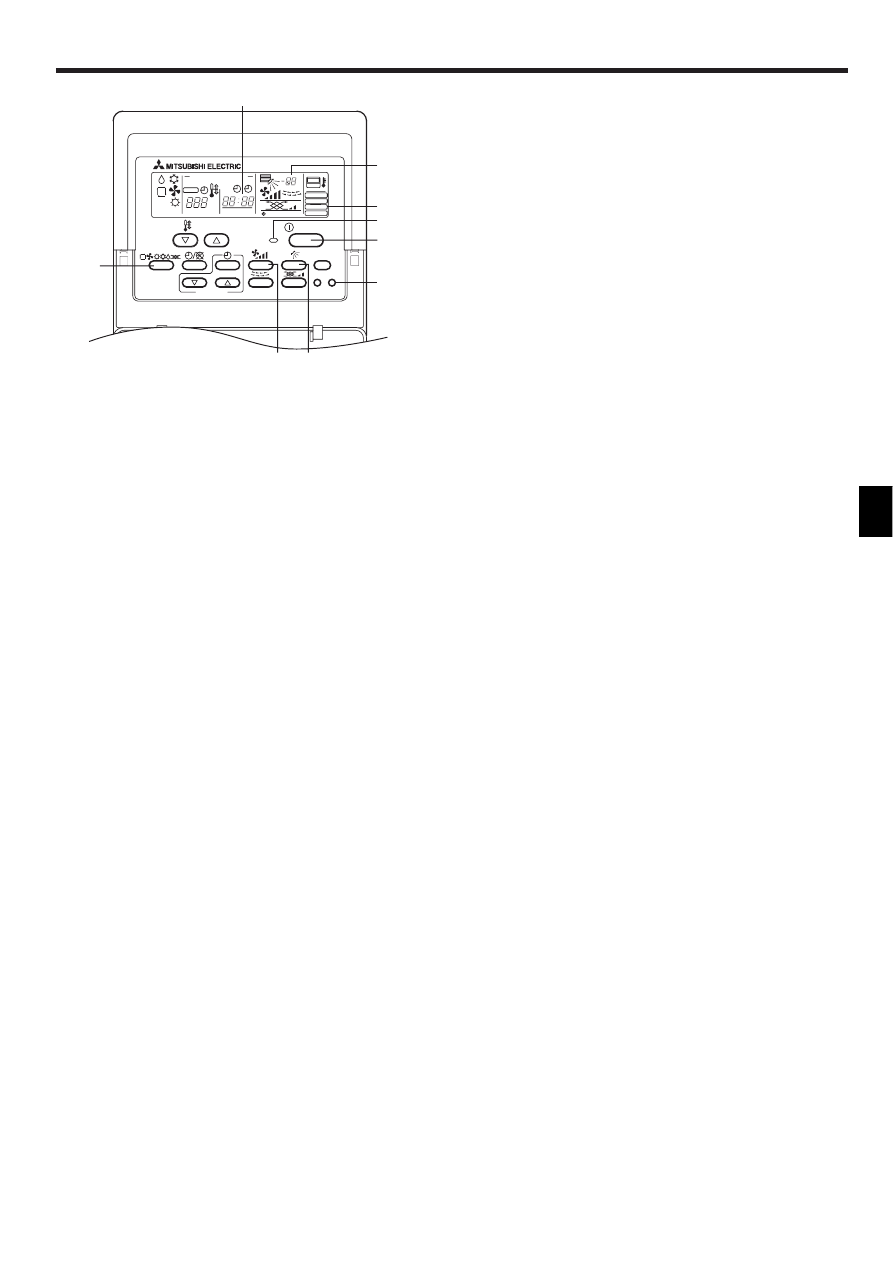
6. Test run (Fig. 6-1)
TIMER SET
PAR-20MAA
ON/OFF
CENTRALLY CONTROLLED
ERROR CODE
CLOCK
ON
OFF
˚C
CHECK
CHECK MODE
FILTER
TEST RUN
FUNCTION
˚C
1Hr.
NOT AVAILABLE
STAND BY
DEFROST
FILTER
CHECK TEST
TEMP.
2
BC
3
4
5
1
A
E
D
1 Press [TEST RUN] button twice → displaying [TEST RUN] on the screen.
2 Press [Selecting operation] button. → Check that wind is blowing out.
3 Press [Fan speed adjustment] button. → Check that the wind speed is changed.
4 Press [Up/down airflow selection] button to change wind direction.
5 Press [ON/OFF] button to clear test run. → Test run stops.
A Lighting in operation
B Displaying inspection code
C Displaying remaining test run time
D Displaying indoor unit’s liquid pipe temperature
E Displaying test run
Note:
• The 2-hour-set timer is activated to automatically stop test run after two hours.
• The remote controller displays the temperature of the indoor unit’s liquid
pipe on the temperature display section during test run.
Fig. 6-1
Wyszukiwarka
Podobne podstrony:
IM PCA RP2 6GA BG79U334H01 Aug 2004
IM PKFY P32 50VGM E BG79U323H02 GB 2004
3. Zmiany w Karcie Nauczyciela od 31.08.2004, Awans zawodowy nauczyciela- moje zebrane materiały
MEDYTACJA $ 08 2004
910030 1400SRM0047 (08 2004) UK EN
1566270 0100SRM1118 (08 2004) UK EN
910110 2200SRM0143 (08 2004) UK EN
USTAWA z 27 08 2004 do egz
1578950 2200SRM1119 (08 2004) UK EN
Prawo Energietyczne z 21 08 2004(1), elektryka
plytka wielofinkcyjna 08 2004
1565181 2000SRM1108 (08 2004) UK EN
DD 3.8 OPBMR W OPERACJACH-POŁĄCZONYCH-11.08.2004, Zajęcia WSOWL, OPBMR
1565183 2200SRM1110 (08 2004) UK EN
Jak zmienić turystę w studenta-26.08.2004, USA
MT 08 2004 Samochód turbinowy
MEDYTACJA 08 2004
Poradnik Kurs tworzenia sklepu internetowego, część 3 Szablony 08 2004
więcej podobnych podstron