
6
Recycling of Polymers
6.1
Introduction
It is certainly true that plastics left lying around after use do not disappear from view and such post-
consumer waste as foam cups, detergent bottles, and discarded film is a visual annoyance. This is because
plastics are not naturally biodegradable. However, to consider this a detriment is a questionable
argument. Rather, it may well be considered an advantage. This is borne out by the fact that recycling
of plastics materials is now an important field in the plastics industry, not just an activity born under
environmental pressure.
Although the plastics industry practiced recycling for many years, attention was mainly focused on the
recycling of industrial scraps and homogeneous post-consumer plastics, which are easy to collect and
reprocess. However, more recently the plastics industry accepted the challenge of recycling of
heterogeneous plastics waste based on new technologies of separation and reprocessing. Scientific
research, scarcely visible only a few years ago, is now a very active, fast-growing discipline, contributing to
the development of newer processes.
According to the type of product obtained from the recycling process and the percentage of the
economic value recovered, the following broad classification of recycling technologies can be made (1)
primary recycling, the reprocessing of plastics waste into the same or similar types of product from which
it has been generated; (2) secondary recycling, the processing of plastics wastes into plastics products
with less demanding properties; (3) tertiary recycling, recovery of chemicals from waste plastics; and (4)
quaternary recycling, recovery of energy from waste plastics.
The processes mainly used to these ends are: direct reuse after separation and/or modification,
chemical treatment or pyrolysis for recovery of monomers and/or other products, and burning
or incineration.
Primary recycling is used when the plastic waste is uniform and uncontaminated and can be
processed as such. Only thermoplastic waste can be directly reprocessed; it can be used alone or, more
often, added to virgin resin at various ratios. The main problems encountered in primary recycling are
degradation of the material resulting in a loss of properties as appearance, mechanical strength,
chemical resistance, and processability. Contamination of plastic scrap and handling of low-bulk
density scrap such as film or foam are additional problems in primary recycling. Primary recycling is
widely performed by plastics processors; it is often considered an avoidance of waste rather
than recycling.
For post-consumer, mixed plastic wastes (MPW), which are unsuitable for direct use, the industry
resorts to secondary recycling methods. There are various technical approaches to secondary recycling of
MPW. These include reprocessing based on melt homogenization using specialized equipment; use of
ground plastics waste as filler; and separation into single homogeneous fractions for further processing,
such as partial substitution of virgin resins and blending with other thermoplastics using
suitable compatibilizers.
6-1
q
2006 by Taylor & Francis Group, LLC

In tertiary or chemical recycling of plastic wastes, polymers are chemically unzipped or thermally
cracked in order to recover monomers or petrochemicals indistinguishable from virgin materials.
Thermal cracking procedures offer viable alternatives by utilizing commingled plastics without
decontamination. In quarternary recycling, energy content of plastics waste is recovered. In most
cases, plastics are burned, mixed with other waste. Incineration of plastics alone creates a number of
problems and requires the use of specially designed incinerators.
6.2
Outline of Recycling Methods
Post-consumer plastic wastes can be divided into two different groups depending on their source: (1)
mixed plastics from the household waste and (2) plastics from the industrial sectors. The first category
involves the medium-/short-life articles that are used in food, pharmaceutical, and detergent packaging,
shopping, and others. The majority of these articles are composed of thin protective films: a variety of
bottles for soft drinks, food, and cosmetics, sheeting for blisters, strapping and thermoformed trays.
There are basically five different polymers that contribute to the total amount of domestic plastic
waste, namely, PE, PP, PS, PVC, and PET. The composition of this MPW can change depending on the
regional habits and seasons of a year, and also on the mode of waste collection. A typical composition
may be PE 39%, PVC 22%, PET 19%, PS 8%, and PP 12% (by wt).
The collection of plastics wastes always yields a polluted product, and this fact poses the need for the
first operation of the recycling process, namely the cleaning of foreign bodies. The machinery required at
this stage may be either manual or automatic type, the former being simpler from the standpoint of
installation. The operations following the first step of clearing are determined by the type of recycling
process to which the material is to be subjected. There are basically two main recycling processes: recycle
of heterogeneous MPW and recycle of selected polymers separated from MPW.
A direct solution to disposal of domestic MPW can be the reuse of the heterogeneous mixture by
processing through extrusion or injection molding technologies using traditional machineries. However,
when MPW is processed, one of the main problems is to find the best compromise between
homogenization and degradation. The optimal processing condition must ensure a good dispersion of
the materials with high melting point (such as PET) in a continuous phase of molten polymers (such as
PVC), avoiding gas bubbles, low-molecular-weight compounds, and cross-linked residues that are
formed by thermal degradation. Some possible applications of such molded mixed plastics are injected
tiles for paving, and extruded profiles for making structural articles such as benches, garden tables,
bicycle racks, fences, and playing facilities. However, because of the incompatibility of the various
components in mixed plastics, the mechanical properties of the molded or extruded products are
rather poor.
The market of park benches, playgrounds, fences, and so on, cannot absorb, in the long run, the
massive amounts of MPW that are produced every year. Hence the possible route to recycling of MPW to
obtain secondary materials with acceptable mechanical properties could be to blend them with virgin
polymers, or, at least, with recycled homopolymers. For example, experimental results [1] of processing
and properties of blends of virgin LDPE and MPW have shown that all mechanical properties, with the
exception of elongation at break, are very similar to those of the virgin material if the MPW content does
not exceed 50%.
The possibility of using MPW as filler for both LDPE and HDPE has been considered [2] as such an
approach, and may offer two important advantages: (1) improvement of the use of huge amounts of
MPW that are generated by municipalities and industries; and (2) savings in nonrenewable raw materials
and energy, both associated with the manufacturing of the virgin materials that can be replaced by
plastics waste. Even if the percentage of plastics waste used as a filler cannot be higher, its common use
may absorb sizable amounts of waste.
A widespread solution, in terms of application and market volume, can be the recycling of single
materials or homogeneous fractions obtained from a differentiated collection system and/or a separation
6-2
Plastics Technology Handbook
q
2006 by Taylor & Francis Group, LLC

process of the mixture. Molded products from single or homogeneous fractions usually show a general
performance far greater than that of products from mixed plastics. To obtain single or homogeneous
fractions, it is useful to separate the mixed domestic plastics into four fractions, namely, polyolefins, PS,
PVC, and PET.
An important preliminary to separation of mixed domestic plastics is the cleaning and selection
operation. A simple method to perform this operation consists of a selection platform where a number of
trained sorters separate the different types of plastics by visual assessment. Because manual selection is
liable to human error, selection platforms may be equipped with detectors such as electronic devices to
check the quality of the selected material.
The drawbacks of the manual platforms—which range from high labor cost to the complexity of labor
management—may be avoided by resorting to automatic platforms. The machines required for such
automation are manifold and the necessity to employ them is related to the quality of the collected
material. Essential machines are rotary screen, light-parts separation equipment, heavy-parts separation
equipment, and aluminum rejection equipment. All such machines are preliminary to the stage of
separation into homogeneous plastic fraction.
Bottles constitute the largest high-volume component of post-consumer plastics and need special
attention in reclaim operation. Since 1988, developments in bottle reclaim systems have made recycling
post-consumer plastics more efficient and less costly. Municipalities, private organizations, universities,
and entrepreneurs have worked closely to develop new collection, cleaning, and sorting technologies that
are diverting larger portions of plastics from landfills to recycled resins and value-added end products.
To collect the high volume-to-weight ratio post-consumer plastics economically, truck-mounted
compactors have been developed that seem to have the most promising future for mobile collection. They
are self-contained and offer, on average, a reduction ratio of 10:1. Simple to operate, compactors accept
all types of plastics, including film, and perform equally well with milk jugs and PET bottles as with
mixed plastics.
Using compactors for on-board truck densification can thus be a cost-effective part of multimaterial
collection programs. Another noteworthy development is that of flatteners and balers, which have also
proven cost-effective under certain conditions. An integrated baler developed by Frontier Recycling
Systems (USA) is fully automatic and capable of handling the plastic throughput of larger and costlier
systems without the corresponding expenditures of space and labor. By producing smaller, high-density
bales, it allows for lower transportation costs of recyclables shipped to market.
In keeping with the progress in densification options, efficient sortation systems have also been
developed. The Poly-Sort integrated sorting line developed by Automation Industrial Control (AIC),
Baltimore, is capable of sorting mixed stream of plastic bottles at a baseline rate of three bottles per
second, or 700 kg/h. With expected advances in scanning and detection, the sorting rate of the system
could double to 1400 kg/h.
Designed to sort compacted bottles, the Poly-Sort system employs conveyors for singulation, and two
devices for color and chemical composition identification. A vibratory conveyor singulates bottles; a read
conveyor transports bottles to an ultrasonic sensor that detects their position; a near-infrared system
detects the resin type; a camera detects the color of the container; a computer integrates data and makes
an identification; air jets divert bottles to the appropriate segregation conveyor or hopper.
The above type of separation is a macroseparation. It may be noted that the methods of separation into
homogeneous fractions fall into three groups: molecular separation, microseparation, and macrosepara-
tion. Molecular separation is based on the dissolution of the various plastics in selective solvents, a
method that is promising but still in the stage of study. Microseparation is a method by which a
suspension medium is used to separate plastics with density higher or lower than the suspension
medium. Macroseparation, which is the separation of plastics when waste materials are still in initial
form, appears to be the most conveniently applicable system, considering the increasing possibilities of
automation it offers. The key to this separation process is the development of an efficient detector system
that can distinguish between type and quality of different plastics in waste materials.
Recycling of Polymers
6-3
q
2006 by Taylor & Francis Group, LLC

Different types of detectors have been developed and many are under development. These are based on
distinctive physicochemical properties of plastics and employ different techniques such as x-ray, near-
infrared spectrophotometry, fluorescence, and optical measurement of transparency and color.
Automatic systems consisting of a platform for selection according to plastics topology, a number of
identification and detection steps, and adequate checks on the efficiency of separation following
detection have been developed. The Poly-Sort system described above is one such example.
Recycle installations take up the separated plastic flakes for further processing. Various elements that
normally compose the item to be recycled are caps made of PE, PE with PVC gaskets, aluminum, labels of
tacky paper with different types of glue, and residues and dirt that have been added during the waste-
collection phase. Various operations that are carried out in a specific sequence because of the problems
posed by the type of material are: grinding to ensure homogeneity of the product, air flotation for
separation of flakes with different specific weight and removal of parts of labels freed by grounding (such
as separation of PVC labels from PET bottle flakes), and finally washing to remove residues. The washing
system consisting of a range of equipment that includes centrifugal cleaners, washing tank, settling tank,
and scraping machines is part of a know-how of various manufacturers.
The majority of municipal solid waste consists of plastics waste, which is often contaminated with
significant amounts of paper. This is not only the case with plastics fraction of municipal solid waste
(PFMW), but also with such industrial waste as used packaging materials, laminates, and trimmings. The
reprocessing of plastics waste contaminated with more than 5% paper is difficult using conventional
plastics processing machinery, and becomes almost impossible at paper levels exceeding 15%. The sorting
operation at a municipal plant normally aims at removing the paper component from the light plastics
fraction to a level well below 1%. However, this operation has not been quite successful because the
material handling side has been difficult and the costs have far exceeded the price of virgin polyolefins.
A simpler solution to the problem of contamination may be to allow for a paper component in the
plastics fraction and to use a processing method that can disintegrate the cellulose fibers into small
fragments such that they act as particulate fillers in the plastics. Such a method has been developed at
Chalmers University of Technology, Gothenburg, Sweden. Known as the CUT-method, the process
makes it possible to reprocess both the PFMW and a number of different industrial plastic waste materials
contaminated with paper [3,4]. The CUT-method, consisting of a prehydrolytic treatment of the paper
component, is an industrially applicable method of reprocessing paper-contaminated plastics waste of
various origins.
The main advantage of the CUT-method is that the plastics fraction and the paper component do not
need to be separated an the hydrolysis does not degrade the plastics component but reduces the chain
length of the cellulose component to a level at which the cellulose fiber becomes extremely brittle and the
shear forces generated in normal plastics processing machinery (compounding extruders and molding
machines) can easily disintegrate the paper parts into small fibrous fragments. It is the disintegration of
the embrittled paper component into an almost pulverized substance that is the key to the success of the
method, since this results in greatly enhanced melt flow properties, better homogeneity, and thus in
improvement in the mechanical properties of the material [5].
The method of hydrolysis used in the CUT-method offers an efficient and economical way of
processing plastic waste, both post-consumer municipal waste and industrial waste, contaminated
with a cellulose component. The presence of cellulose gives a desired stiffness to the final product, as
studies have shown [4,5]. Such plastics product can be used in several applications, such as
artificial wood.
Plastics wastes from industrial sectors concern mostly the medium-/long-life articles, as plastics have
played a fundamental role in the exceptional growth of production technology seen during recent years in
these sectors, and in particular the automotive industry. Because of the advantage in design and
functionality, plastics are now an indispensable part of any kind of car; the amount of polymers employed
to build a car has risen to about 20% from a mere 5% in 1973, with a corresponding increase in the
quantity of nonmetallic waste during scrapping. The main problem of plastic wastes from all industrial
sectors, and in particular the car industry, is the large variety of materials employed to build a single
6-4
Plastics Technology Handbook
q
2006 by Taylor & Francis Group, LLC

component or system, for example, a dashboard. This takes place because of the sophisticated and
complex mission that the system must perform. The large number of plastics used and the
disproportionately high costs in the dismounting of the different plastic pieces of a car represent an
intractable waste-recovery problem and thus have a negative impact on the recycling process. As a result
of this, only the metallic fraction is recovered, while the plastic materials continue to be eliminated by
deposition in refuse dumps.
An alternative approach to the recovery of automotive plastics is therefore to use them as large, easily
removable components that offer potential for reclamation as well-characterized individual polymers.
Some particularly complex components such as vehicle front- and rear-end systems, exhibit special
suitability for manufacture in plastics instead of metals because of their ease of production and assembly.
It is generally recognized that improvements in automotive scrapyard economics may be best achieved by
the prior removal from vehicles of such large polymeric components and their recycling as well-
characterized plastic fractions. For example, plastic fuel tanks of HDPE are now in common use and
represent the most common recyclable plastic component. Trials with material recovered from used
plastic fuel tanks have shown promising results for the manufacture of new tanks [6].
A concept that is being developed to solve the recycling problems of plastics from industrial sectors,
and in particular the car industry, is based on the use of materials of the same family for all components
of the plastic systems to be recycled at the life end. This allows an easy and direct recycling of the scraps
and the recovery of the whole system. Greater recycling efficiency can be obtained when the following two
basic requirements are satisfied: (1) materials compatibility through materials homogeneity, and (2)
easier disassembly through planned design. This concept has been first applied to the automotive sector,
where the environmental problems have become of primary importance; however, it could be also
applied to other products, i.e., appliances and building materials. There are two tasks in developing this
concept: to develop new advanced materials in individual categories of polymers and to promote
new technologies.
Consider, for example, the automotive industry. Although many polymers are used in cars today, the
industry tends to favor more and more polypropylene use due to a large range of properties available.
New developments in polyolefin-based materials have thus created a family of polypropylene products
with a wide range of physical properties, including the ability to be easily recycled. When utilized by
automotive and product designers as a part of a design for disassembly strategy, these compatible
materials will yield large subassemblies that can be reclaimed with a minimum of handling [7,8]. In each
project, the design incorporates readily identifiable hard point connections between the polypropylene
components and the metal automobile subframe. This allows personnel in recycling centers to remove
these parts quickly and in large pieces that can be completely reground and recycled. This concept has
been applied to car dashboards and interior vehicle components like floor covering, trim, and door
panels, as well as bumpers.
Blends of EPDM rubbers with polypropylene in suitable ratios have been marketed as thermoplastic
elastomers (TPE), also commercially known as thermoplastic polyolefin elastomers (TPO). These
heterophasic polymers, characterized by thermoreversible interaction among the polymeric chains,
belong to a broad family of olefinic alloys that can now be produced directly during the polymerization
phase, unlike blended TPE and TPO, and various compositions (with various compounding additives)
can be formulated which are primarily tailored to meet different requirements of most of car
applications. The TPE-based synthetic leather and foam sheets are typical examples.
In order to obtain all-TPE recyclable applications, different assembly techniques have been specifically
studied to obtain the basic composite structures [8,9]. The most interesting technique is one that allows
simultaneously thermoforming, embossing, and coupling to be obtained in one stage of operation,
yielding a foamed synthetic leather bilayer on a rigid support (all TPE based) without adhesives. With
new designs for recycling, dashboard, floor covering, and other interior components such as door panels,
pillar trim, and rear shelf have been made of the same chemical material (polypropylene) in different
forms, thus providing an important aid to the recycling of plastic.
Recycling of Polymers
6-5
q
2006 by Taylor & Francis Group, LLC

Lead-acid batteries from automotive applications normally have a shorter service life than the car
itself. The logistics system for used car batteries is geared to lead recycling. However, the first battery
reprocessing step yields not only lead but also polypropylene in a form of the casing fragments.
Accordingly, the polymer is available without additional cost. As the casing makes up a substantial part
(7%) of the total battery, the quantities of polypropylene obtained are sufficient to warrant the operation of a
plastics recycling plant. For example, BSB Recycling GmbH in Braubach, Germany, a subsidiary of Metall-
gesellschaft AG, operates secondary lead smelter for lead recovery from postuse lead-acid batteries [10].
They process some 60,000 tons of batteries per annum, which accounts for half of the used battery
volume to be disposed in the western states of Germany. BSB started to segregate the polypropylene from
the battery casings and route it to a separate recycling process as far back as 1984. For the recycling
process, a quality assurance system geared to the specific requirements of the applications has been
developed and implemented.
Polyolefins and poly (ethylene terephthalate) (PET) are the most frequently recycled polymers obtained
from both the domestic and industrial plastics wastes, and as such they have received most attention in the
recycling research and technology. PET is one of the largest recycled polymers by volume [11], because it is
suitable for practically all recycling methods [12]. Over 50% of the PET film produced in the world is used
as a photographic film base. The manufacturers of these materials have long been interested in PET film
recovery. An important motivation for this has been the fact that photographic films are usually coated
with one or more layers containing some amount of rather expensive silver derivatives.
Silver recovery makes PET-base recovery more economical. In a typical way of operation, PET film
recycling is thus coupled with the simultaneous recovery of silver, for example, by washing with NaOH
and follow-up treatment. PET-recycling by direct reuse, if the washed PET-film scrap is clean enough to
be recovered by direct reextrusion, is by far the most economical process. However, this process is most
suited for the recovery of in-production wastes. For customer-recollected PET-film, which may have a
higher degree of contamination, other technologies are to be applied.
There exists a hierarchy in PET-film and plastics recycling technologies depending, first of all, on the
degree of purity of PET scrap to be handled, and secondly, the economics of the process. For the cleanest
PET grade, the most economical process, i.e., direct reuse in extrusion, is self-explanatory. For less-clean
PET waste, it is possible to reuse them after a modification step (partial degradation, e.g., by glycolysis) at
a reasonably low price. More-contaminated PET waste must be degraded into the starting monomers,
which can be separated and repolymerized afterwards, of course at a higher cost.
Polyethylene films from greenhouses, although highly degraded by UV radiation, are recycled by
various means leading to manufacture of films and molded products with low mechanical properties.
Problems in the recycling of greenhouse films arise form the presence of products of photooxidation,
which significantly affect the properties of a recycled material. An interesting possibility of use of
photooxidized PE in blends with nylon-6 to improve blend compatibility has been demonstrated [13,14].
These follow from the earlier efforts [15,16] to compatibilize blends of polyamides and polyolefins
(which are potentially very interesting, but, because of the strong incompatibility of both polymers, yield
products having poor properties) with the use of functionalized polyolefins that can react with the amino
groups of polyamides, giving rise to copolymers and thus stabilizing the blend.
Such functionalization, in general a long and extensive step, is mostly performed by chemical
modification of the polyolefin structure. However, studies have demonstrated [13] that photooxidized
PE offer similar results. Thus the use of recycled (photooxidized) greenhouse PE in blends with nylon
give rise to PE/nylon graft copolymers during processing, which improve the mechanical properties of
the resultant material. The graft copolymers act as compatibilizing agents; the properties of nylon-rich
blends (80 wt% nylon-6) thus are found to be very similar to those of blends compatibilized by PE, and
which is initially functionalized by chemical means. Moreover, in coextrusion, a good adhesion between
the two layers (nylon and recycled PE) of coextruded films helps to avoid a need for the addition of a
third layer binding two incompatible phases.
Chemical means such as glycolysis, methanolysis, and hydrolysis are good at unzipping only the
condensation polymers—such as polyester, nylon, and polyurethanes—to facilitate chemical recycling.
6-6
Plastics Technology Handbook
q
2006 by Taylor & Francis Group, LLC

Addition polymers, such as vinyls, acrylics, fluoroplastics, and polyolefins, can hardly be reprocessed
except that, if they are sorted, they may be converted into powder by grinding operation and mixed with
respective virgin resins for remolding into finished goods or, in some cases, blended with other resins
using suitable compatibilizers to make useful end-products of commercial value.
Tertiary recycling of addition polymers require pyrolysis, which is a more aggressive approach. For
mixed or unsorted plastics in particular, it is a practicable way of recycling. Pyrolysis is the thermal
degradation of macromolecules in the presence of air. The process simultaneously generates oils and
gases that are suited for chemical utilization.
The advantage of pyrolysis over combustion (quaternary recycling) is a reduction in the volume of
product gases by a factor of 5–20, which leads to considerable savings in the gas conditioning equipment.
Furthermore, the pollutants are concentrated in a coke-like residue matrix. It is possible to obtain
hydrocarbon compounds as gas or oil.
The pyrolysis is complicated by the fact that plastics show poor thermal conductivity, while the
degradation of macromolecules requires considerable amounts of energy. The pyrolysis of mixed plastic
wastes and used tires has been studied in melting vessels, blast furnaces, autoclaves, tube reactors, rotary
kilns, cooking chambers, and fluidized bed reactors [17,18].
Rotary-kiln processes are particularly numerous. They require relatively long residence times (20 min
or more) of the solid wastes in the reactor. Moreover, due to the large temperature gradient inside the
rotary kiln, the product spectrum is very diverse. For this reason, the gases and oils generated by the
pyrolysis are normally used for the direct generation of energy and the process may well be considered as
a quaternary recycling process.
For chemical recycling of mixed plastics, the fluidized bed pyrolysis has turned out to be particularly
advantageous. The fluidized bed is characterized by an excellent heat and mass transfer as well as constant
temperature throughout the reactor. This results in small dwell times (a few seconds to a 1.5 min
maximum) [18] and largely uniform product spectra. The fluidized bed is generated by a flow of air or an
inert gas (nitrogen) from below through a layer of fine-grained material, e.g., sand or carbon black. The
flow rate is sufficient to create turbulent motion of particles within the bed. Using a fluidized bed
pyrolysis, 25–45% of product gas with a high heating value and 30–50% of an oil rich in aromatics could
be recovered [18]. The oil is comparable to that of a mixture of light benzene and bituminous coal tar. Up
to 60% ethylene and propylene are produced by using mixed polyolefins as feedstock. Moreover,
depending on the temperature and the kind of fluidizing gas (nitrogen, pyrolysis gas, and steam) different
variants of the fluidized bed pyrolysis process can be carried out, yielding only monomers, BTX-
aromatics, high boiling oil, or gas.
A promising concept that is receiving increasing attention is recycling plastics to refinery cokes, where
pyrolysis units and a well-developed infrastructure are already in place. The main hindrance to the
execution of this concept is the presence of contaminants (including chlorine and nitrogen) in the
plastics stream, as well as the need to turn plastics into a liquid form that the refinery can handle. Projects
are in place to address these issues. Initial small-scale pyrolysis, dissolving plastics into other refinery
feedstocks, or turning solid wastes into a slurry, are some of the options that have received attention.
Efforts have also been made in some refineries to convert mixed plastics into a petrochemical feedstock by
catalytic hydrogenation. In the refinery, the aim of tertiary recycling is not to displace regular refinery
capacity, but to use plastic waste as a very minor stream. However, even if all refineries with cokers took
only 2% of their capacity as plastic waste, it would be extremely significant.
Mention should be made of a plastics liquefaction process that has been developed jointly by the
Japanese Government Industrial Laboratory, Hokkaido, Mobil Oil Corporation, and Fuji Recycle
Industry. The process can treat polyolefinic plastics (polyethylene, polypropylene, and polystyrene) or
their mixtures by a combination of thermal and catalytic cracking to produce gasoline, kerosene, and gas
oil fractions of about 85%. Recovered liquid and gas are separated by cooling and the gas is used as
in-house fuel. The technology is unique in using proprietary Mobil ZSM-5 catalyst and has been
described as an ultimate recycling technology [19].
Recycling of Polymers
6-7
q
2006 by Taylor & Francis Group, LLC

A brief overview of several important aspects of plastics recycling and development in the field has
been given above. Some of the topics that have been highlighted in this review will now be elaborated
further in the following sections. In addition, waste recycling problems and possibilities relating to a
number of common plastics will be discussed.
6.3
Recycling of Poly (Ethylene Terephthalate)
The largest use of poly (ethylene terephthalate) (PET) is in the fiber sector, with PET film and PET bottles
representing only about 10% each of the total PET volume produced annually. A large percentage of the
total PET output comprising films, plastics, and fibers is recycled by various methods and for several
applications, which makes PET one of the largest in volume of recycled polymers in the world.
Contributing to this is the suitability of PET for practically all recycling methods, which include
direct reuse, reuse after modification, recovery of monomers and other low-molecular-weight
intermediates, and incineration. Any particular method is selected on the basis of the quality of waste
and scrap, the economy of the process, and the convenience of the operation.
Contamination of post-consumer PET (POSTC-PET) is the major cause of deterioration of its
physical and chemical properties during reprocessing. POSTC-PET is contaminated with many
substances: (1) acid producing contaminants, such as poly(vinyl acetate) and PVC; (2) water; (3)
coloring contaminants; (4) acetaldehyde; (5) other contaminants such as detergents, fuel, pesticides, etc.,
stored in PET bottles.
The most harmful acid to the POSTC-PET recycling process are acetic acid, which is produced by
poly(vinyl acetate) closures degradation, and hydrochloric acid produced by the degradation of PVC. The
acids act as catalysts for the chain scission reactions during POSTC-PET melt processing. Thus, the
presence of PVC, as little as 100 ppm, would increase POSTC-PET chain scission [20]. Water reduces
molecular weight (MW) during POSTC-PET recycling through hydrolysis reactions at the processing
temperature (2808C). Moisture contaminants should be below 0.02% to avoid such MW reduction [21].
Acetaldehyde is present in PET and POSTC-PET, as it is a by-product of PET degradation reactions.
The migration of acetaldehyde into food products from PET containers was a major concern in the early
stages of developing the recycling process. Acetaldehyde being highly volatile, it can be minimized by
processing under vacuum or by drying. Stabilizers such as 4-aminobenzoic acid, diphenylamine, and 4,5-
dihydroxybenzoic acid are added to PET in order to minimize the generation of acetaldehyde [22].
6.3.1
Direct Reuse
This method, also called recycling by re-extrusion or melt recovery, is used for relatively pure PET waste
such as cleaned consumer bottles or in-house waste. The method is based on the same principles as the
original equilibrium polycondensation reaction:
H
[ ET ]
OCH
2
CH
2
OH
[ OCH
2
CH
2
OOC
[ET]
≡
EG
≡
HOCH
2
CH
2
OH
(ethylene glycol)
(ethylene terephthalate)
OCH
2
CH
2
OH
OCH
2
CH
2
OH + EG
CO ]
H
n
m
m + n
[ ET ]
[ ET ]
+
H
ð6
:1Þ
As polymer buildup and polymer degradation are taking place in the melt simultaneously, the reaction
conditions have to be controlled very carefully in order to obtain the desired molecular weight and
molecular weight distribution for the end use. In theory, this seems rather simple; in practice, however, a
large amount of determining parameters (temperature, environmental atmosphere, holding time in a
melt state, amount of impurities, type of used catalysts, stabilizers, etc.) have to be kept under control.
6-8
Plastics Technology Handbook
q
2006 by Taylor & Francis Group, LLC
A practicable reextrusion process was worked
out and described by Syntex Chemie nearly forty
30 years ago [23]. This method—with some
modifications—is still being used. The greatest
recycler of fiber waste in the U.S. is Wellman;
they recover PET fiber and bottle waste for home
furnishing and nonwoven materials by a
similar method.
Customer-recollected waste from fiber and
textiles consists mainly of continuous filaments or
staple fibers, which may be contaminated with
dyestuffs, finishes and knitting oils, and other
fibers such as cotton, wool, rayon, nylons, and
acrylics; they are the most difficult-to-recover
products.
A different picture can be presented for the PET
bottles. In the environmentally active states in the
U.S., 80–95% of the PET bottles sold are recol-
lected and recycled. In Europe and in Japan where
recycling has started earlier than in the U.S.,
various reclamation and reprocessing methods have been worked out and applied in practice. Because
these processes are usually proprietary, the details of their operation are not known.
The larger use of PET film is as a photographic film base, which accounts for over 50% of the PET film
produced in the world. The manufacturers of these materials, mainly Agfa-Gaevert, Eastman Kodak, du
Pont de Nemours, Fuji, 3M, and Konishiroku, have long been interested in the recovery of PET film
because of its content of rather expensive silver derivatives. Recycling of PET-film waste in production,
which may amount to 25–30% of the total output, is almost complete by these manufacturers.
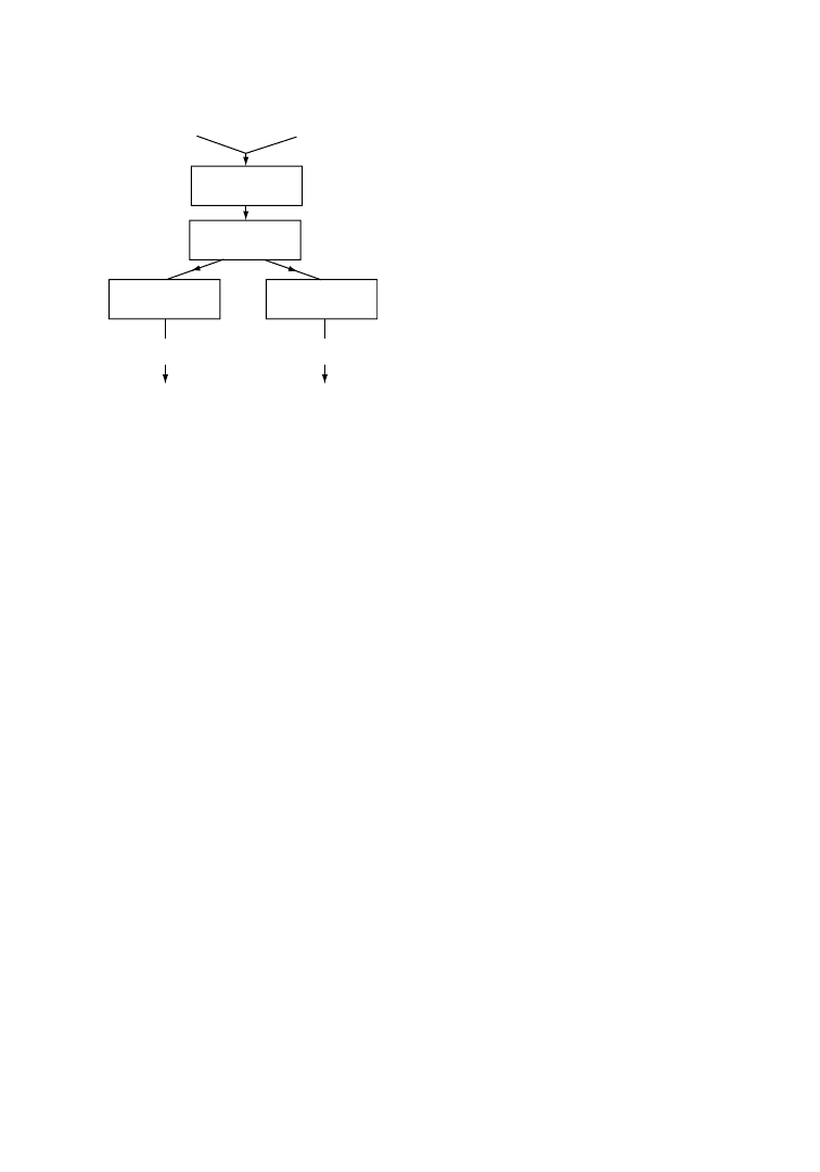
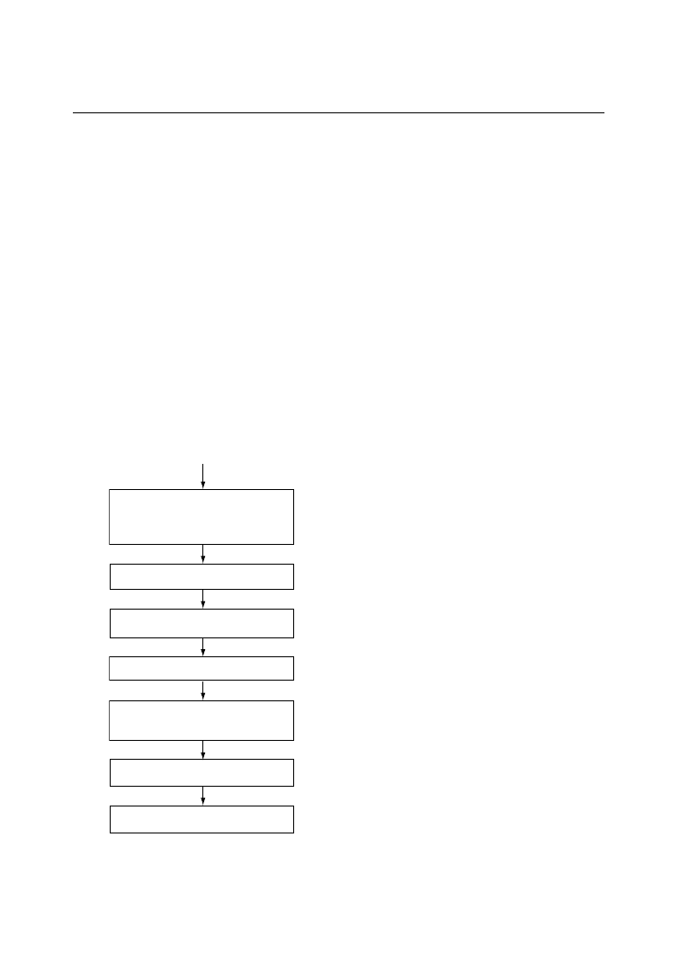
In a typical way of operation, PET film recycling is coupled with the simultaneous recovery of silver, as
represented schematically in Figure 6.1. In the first step of the process, photographic emulsion layers
containing silver are washed with, for example, NaOH, and after separation, silver is recovered on one
side and cleaned PET waste on the other side [24]. Careful analysis is necessary to ensure that the washed
PET-film scrap is clean enough to be recovered by direct extrusion.
The most obvious way of adding the recycled PET flakes is after the usually continuous polymerization
and before the PET melt enters the extruder screw [25]. Such a procedure, however, has two main
drawbacks: first, the highly viscous melt is difficult to filter (to eliminate possible gels or microgels); and
second, other impurities (e.g., volatiles, oligomers, and colored parts) cannot be eliminated any more. In
order to remove these disadvantages, several alternative modes have been worked out. A method to add
recycled PET to the polymerization batch reactor during the esterification step was described by du Pont
as early as 1960 [26]. Such a method shows the following advantages over the method described above:
filtration can take place in the low-viscosity phase, and volatiles can be eliminated during the
prepolymerization phase.
PET recycling by direct reuse, as described above, is by far the most economical process. However, it is
useful in practice only for well-characterized PET wastes that have exactly known chemical composition
(catalysts, stabilizers, and impurities). Therefore, the method is ideally suited for the recovery of
in-production wastes, but it may not be suitable for post-consumer PET film.
6.3.2
Reuse after Modification
For post-consumer PET waste having a higher degree of contamination, technological processes based on
degradation by either glycolysis, methanolysis, or hydrolysis can be used. These yield products that can be
Photographic
film waste
NaOH washing
Filtration
Silver
remelting
Reclaimed
silver
Reuse
Recovered
PET
Re-extrusion
Washing
and drying
PET
Ag
FIGURE 6.1
Combined recovery of silver and PET.
(After De Winter, W., Die Makromol. Chem., Macromol.
Symp., 57, 253, 1992. With permission.)
Recycling of Polymers
6-9
q
2006 by Taylor & Francis Group, LLC
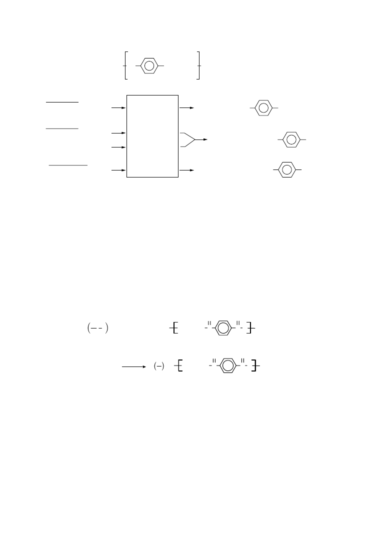
isolated. The principles of chemical processes involved in these methods are schematically represented in
Figure 6.2.
Hydrolysis and methanolysis of PET regenerates the starting monomers. Thus, terephthalic acid (TPA)
along with ethylene glycol (EG) are obtained by hydrolysis, while methanolysis yields EG and dimethyl
terephthalate (DMT) among other products. Stopping short of complete depolymerization, glycolysis
degrades long polymer chains (with typical repeat sequences of 150 units) into short-chain oligomers
(repeat sequences of 2–10 units) having hydroethyl end groups.
6.3.2.1
Glycolysis
The addition of EG–PET reverses the polymerization reaction. This can be stoichiometrically
represented by
1 HOCH
2
CH
2
OH
+
O
C
O
O
CH
2
CH
2
OH
x
Cat.
Δ
HO
CH
2
CH
2
O C
HO
CH
2
CH
2
O C
O
C
O
O
CH
2
CH
2
OH
y
y
x
(EG)
(PET)
('Monomer')
x
y
ð6
:2Þ
where xZaverage number of repeat units in polymer and yZaverage number of repeat units in
‘monomer.’ When yZ1, monomerZdihydroxyethyl terephthalate (DHET).
Glycolysis thus represents a compromise between regeneration of starting ingredients by methanolysis
or hydrolysis and direct melt recovery. It is less costly than the former and more versatile than the latter.
The resultant, easily filtered, low viscosity ‘monomer’ can be repolymerized to a useful higher molecular
weight product. A typical flow sheet of the process is shown in
PET scrap suitable for glycolytic recycle includes production waste, fibers, film, flake, and bottles. In a
practical system, major contaminants are separated from feedstocks, e.g., bottle waste is cleaned and
separated from a polyethylene base, paper labels, metallic caps, and liners. For many end uses, colored
PET must also be segregated. (Highly modified copolymers, glass-reinforced resin, fiber, or fabric blends
are not suitable for glycolysis. These can only be recovered by methanolysis/hydrolysis.) Since reaction
time depends on surface area, PET feedstocks must be reduced to relatively small particles by grinding,
cutting, etc.
HO
CO
COO(CH
2
)
2
O
H
n
PET
Mixture of
a score of
intermediates
of varying
molecular
weights
Glycolysis
Hydrolysis
PET + HO – CH
2
– CH
2
– OH
PET+ CH
3
OH
PET + NaOH (H
2
O)
or
PET + H
2
SO
4
(H
2
O)
HO– CH
2
– CH
2
– O – OC
HO – CH
2
– CH
2
– OH + HOOC
HO – CH
2
– CH
2
– OH + H
3
C– OOC
CO – O – CH
2
– CH
2
– OH
Methanolysis
COOH
COOCH
3
FIGURE 6.2
PET degradation by glycolysis, hydrolysis, and methanolysis. (After De Winter, W. 1992.
Die Makromol. Chem., Macromol. Symp., 57, 253.)
6-10
Plastics Technology Handbook
q
2006 by Taylor & Francis Group, LLC
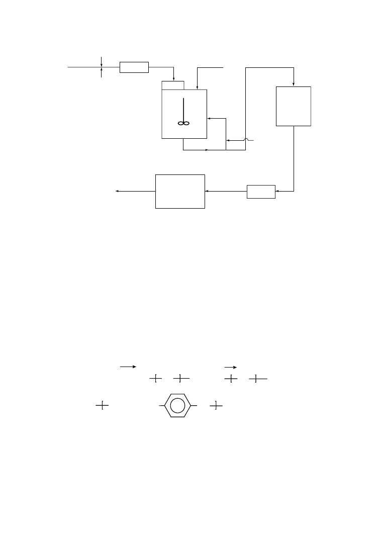
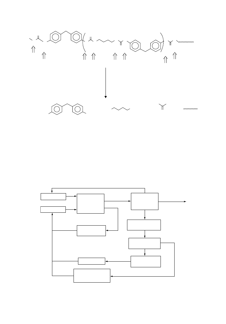
The du Pont company [27] published many details covering the glycolytic recycling of PET. Goodyear
has also developed a PET recycling process based on glycolysis that is called REPETE [28]. In a batch
process, a molten ‘monomer’ heel is left in the reactor to allow the feedstock/glycol mixture to reach
optimum reaction temperatures. In a continuous process (Figure 6.3) some of the molten ‘monomer’ is
recycled to a stirred reactor to accomplish the same function. High glycol/terephthalate (G/T) ratios lead
to more complete glycolysis but lower the maximum temperature, increasing the reaction time. A ratio of
1.7–2.0 G/T is a practical compromise [29]. An ester exchange catalyst as zinc or lithium acetate is usually
added to increase the rate of glycolysis. Reaction temperatures of 220–2408C and times of 60–90 min are
typical. The reactor is operated under a positive pressure to prevent forming an explosive mixture of air
and glycol vapors.
The major side reaction is the production of ethers:
CO
OCH
2
CH
2
OOC
CH
2
CH
2
O
OCH
2
CH
2
OH
HOCH
2
CH
2
OCH
2
CH
2
OH
2HOCH
2
CH
2
OH
Acid
ET
≡
HO
ET
ET
n
m
ð6
:3Þ
Since this reaction is acid catalyzed, it can be minimized by adding a buffer such as sodium acetate or
by adding water [30]. Lithium acetate catalyst also produces less ethers than since acetate. Some other
side reactions are the formation of aldehyde, cyclic trimer of ET, and dioxane. Oxidation of glycol ends
produce aldehydes that lead to colored compounds. Traces of dioxane can form from the cyclization
of glycol.
If other glycols, such as diethylene glycol, are substituted for ethylene glycol, the corresponding
oligomers are formed. These can subsequently be polymerized with aliphatic diacids as adipic or 4,4
0
-
diphenylmethane diisocyanate to give rigid elastomers [31]. Additive to control luster, color, and so on
can be added in the usual manner before and after polymerization.
Holding
tank
(180–200
°
C)
Return
monomer
Catalyst
Additives
Chip or
direct use
Metal
detector
Trap
EG
Cat.
Reactor
200
−
240
°
C
Clean
feedstock
Grinder
Polymerizer
Filter
FIGURE 6.3
Flow diagram of a typical system for glycolytic recycling of PET waste. (After Richard, R., ACS Polym.
Prepr., 32(2), 144, 1991. With permission.)
Recycling of Polymers
6-11
q
2006 by Taylor & Francis Group, LLC
Primary uses for PET from glycolytic recycle are geotextiles, fibers for filling products, nonwovens, and
molding resins where color, strength, and control of dyeability is not important. Recovered polymer can
be added to virgin polymer for films, fibers, and molding resins.
6.3.2.2
Methanolysis
PET waste obtained in the form of film, bottles, and fibers can be very conveniently converted into its raw
materials dimethyl terephthalate (DMT) and ethylene glycol (EG) by methanolysis. The process involves
heating the PET waste with methanol at 240–2508C and 20–25 kg/cm
2
pressure in the presence of catalysts
such as metal oxalates and tartrates. Once the reaction is completed, DMT is recrystallized from the
EG-methanol molten liquor, and distilled to obtain polymerization-grade DMT. Also EG and methanol
are purified by distillation. Eastman Kodak has been using such a process for recycling of x-ray films for
nearly 40 years and it is still improving the process [32], e.g., by using superheated methanol vapor to
allow the use of ever more impure PET waste. Important factors that have to be dealt with in this process
are avoiding coloration due to aldehyde formation and minimizing the formation of either glycols.
6.3.2.3
Ammonolysis
PET wastes can be converted via ammonolysis to paraphenylenediamine, which is a basic raw material for
the high-modulus-fiber Kevlar or for high-value hair dyes. The chemical basis for this process is a
modified Hoffman rearrangement. The synthesis may be done via the following three stages [33]:
OCH
2
CH
2
OC
C
O
n
O
NH
3
H
2
NC
CNH
2
+ HOCH
2
CH
2
OH
O
O
H
2
NC
CNH
2
ClHNC
CNHCI + HCl
Cl
2
NaOH
O
O
O
O
ClHNC
CNHCI
H
2
N
NH
2
+ NaCl + Na
2
CO
3
O
O
( I )
( II )
( III )
Step 1
Step 2
Step 3
In the first step, granulated PET is suspended in ethylene glycol and treated with gaseous ammonia at
100–1408C. In this reaction, the ethylene glycol also acts as a catalyst. The product terephthalimide (I) is
insoluble in the medium and thus may be isolated. In the second step, terephthalimide (I) is suspended in
water and chlorinated vigorously with chlorine gas. The resulting terephthalic bis-chloramide (II) is
treated with NaOH solution to obtain paraphenylene diamine (III). An important aspect of this process
is that paraphenylenediamine so obtained is completely free from its ortho and meta isomers and its
production cost is much less than the market price. ICI has reported an alternative single-step process for
conversion of PET to paraphenylenediamine by ammonolysis in the presence of hydrogen gas.
6.3.2.4
Hydrolysis
PET can be completely hydrolyzed by water at higher temperatures and pressure in the presence of
catalysts (acidic as well as alkaline) to regenerate the monomers, terephthalic acid, and ethylene glycol.
6-12
Plastics Technology Handbook
q
2006 by Taylor & Francis Group, LLC

While both acid- and base-catalyzed systems are completely realistic, their usefulness under practical
production conditions remain controversial. As far as acid hydrolysis is concerned, the large acid
consumption and the rigorous requirements of corrosion resistance of the equipment make profitability
questionable. Moreover, the simultaneous recovery of TPA and EG, requiring the use of ecologically
undesirable halogenated solvents, is difficult and not economical. For the alkaline hydrolysis process,
also, the profitability is strongly determined by the necessity of expensive filtration and precipitation
steps. In spite of the fact that the majority of newer industrial PET-synthesis plants are based on the TPA
process rather than on the DMT process [34], the hydrolytic method of PET recycling has not
gained favor.
6.3.2.5
Depolymerization in Supercritical Fluids
The supercritical fluid over its critical point has high density, such as in liquid state, and high kinetic
energy as in a gas molecule. Therefore the reaction rate is expected to be higher than the reaction under
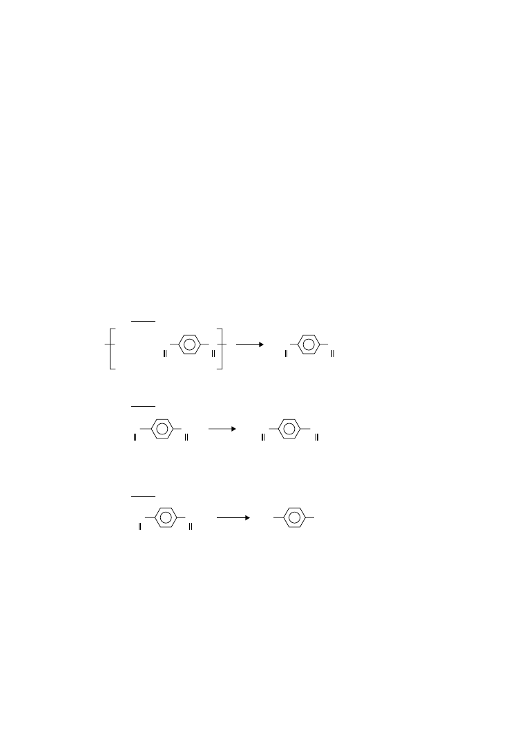
liquid state conditions. PET is depolymerized quickly by solvolysis in supercritical water [35] or
supercritical methanol [36]. The main products of PET depolymerization in supercritical methanol
are dimethyl terephthalate (DMT) and ethylene glycol (EG), as shown in Figure 6.4. The depolymeriza-
tion is carried out typically at temperatures between 543 and 603 K under pressures of 0.1–15 MPa for a
reaction time of 3–60 min. For example, at 573 K, sample/methanol ratio 1/5 (by wt) and reaction
pressure 14.7 MPa, DMT yield is reported [37] to be 98 per cent in 30 min.
It has been suggested that random scission of polymer chain takes place predominantly in the
heterogeneous phase during the initial stage of PET depolymerization in supercritical methanol
producing oligomers, whereas specific (chain end) scission to monomers proceeds predominantly in
the homogeneous phase during the final stage.
6.3.2.6 Enzymatic Depolymerization
In 1977, Tokiwa and Suzuki reported that some lipases, which are extracellular enzymes that usually
cleave esters in oils and fats, are also able to attack ester bonds in some aliphatic polyesters and can
depolymerize such materials [38]. Aliphatic polyesters, however, exhibit only limited useful properties
for many applications. Aromatic polyesters, such as PET and PBT, which are widely applied because of
their excellent properties, are not attacked by hydrolytic enzymes. This led to the development of
aliphatic-aromatic polyesters as biodegradable plastics that present a compromise between biodegrad-
ability and material properties [39]. Recently, however, Mu¨ller et al. [40] have isolated a hydrolase
(TfH) from Thermofibida fusca which is able to depolymerize the aromatic polyester PET at a high rate
in contrast to other hydrolases such as lipases. They have demonstrated for the first time that
commercial PET can be effectively hydrolyzed by an enzyme at a rate that does not exclude a biological
recycling of PET. The effective depolymerization of PET with the enzyme TfH will result in water
C
O
C
O
C
O
C
O
O
O
CH
2
CH
2
2
n CH
3
OH
n H
3
CO
CH
3
n HOCH
2
CH
2
OH
O
n
PET
Supercritical
methanol
EG
DMT
+
+
FIGURE 6.4
Main reaction of PET depolymerization in supercritical methanol.
Recycling of Polymers
6-13
q
2006 by Taylor & Francis Group, LLC

soluble oligomers and/or monomers that can be reused for synthesis. In contrast, a microbial treatment
of PET may not be appropriate for recycling purposes, since monomeric and oligomeric depolymeriza-
tion products would be consumed by the microorganisms involved or inhibit their action and
growth [40].
It is likely that the degradability of PET with hydrolases such as TfH strongly depends on the polymer
crystallinity and the temperature at which the enzymatic degradation takes place [40]. The effective
enzymatic PET hydrolysis will thus be expected to occur only below a certain critical degree of
crystallinity. However, for bottle manufacture polyesters with low crystallinity are preferred for high
transparency, thus increasing the susceptibility of PET to enzymatic attack.
One reason for the high activity of TfH hydrolase towards PET may be the high temperature (558C)
optimum, which is a result of its origin from a thermophilic microorganism. However, differences in the
degradation behavior between TfH and the other lipases may also be due to differences in the structure of
the enzymes, possibly enabling TfH to attack less mobile polyester segments and degrade PET at a
surprisingly high rate.
6.3.3
Incineration
For PET wastes containing a large amount of impurities and other combustible solids it is more profitable
to resort to quaternary recycling, that is, energy recovery by burning. Research along this line has been
performed, particularly in Europe and Japan, since the early 1960s. Strong emphasis has been laid on the
optimization of incinerators with regard to higher temperature of their operation and reduction of the
level of air pollution.
Having a calorific value of ca. 30.2 MJ/kg, which is about equivalent to that of coal, PET is readily
suited for the incineration process. However, like other plastics its combustion requires 3–5 times more
oxygen than for conventional incineration, produces more soot, and develops excessive heat that thus
calls for special incineration equipment to cope with these problems.
Several processes have been developed [41–43] to overcome the technological drawbacks of plastics
incineration cited above. These include continuous rotary-kiln processes; a process for glass-reinforced
PET; a combined system for wood fiber and PET to provide steam to power equipment; and a fluidized
system for pyrolysis, in combination with silver recovery from photographic film. Incineration of
photographic film raises the additional problem of the formation of toxic halogenated compounds due
to the presence of silver halides.
Incineration of PET is usually carried out at temperatures around 7008C, since at lower temperatures
waxy side products are formed, leading to clogging, while at higher temperatures the amount of the
desirable fraction of mononuclear aromatics in the condensate decreases. A representative sample
pyrolyzed under optimum conditions yields, in addition to carbon and water, aromatics like benzene and
toluene, and a variety of carbon–hydrogen and carbon–oxygen gases. Studies have been made [44]
relating to the formation of dioxines and residual ashes containing heavy metals and other stabilizers.
While most problems arising during incineration of PET can be resolved, it is evident that quite a few
hurdles remain to be overcome before an economically feasible and ecologically acceptable industrial
technical process becomes available.
In conclusion, it may be said that there exists a clear hierarchy in PET-film recycling technologies.
Two most important criteria of classification are the degree of purity of PET scrap to be handled and
the economics of the process. While for the cleanest PET grade the most economical process is direct
reuse in extrusion, for less-clean PET samples it is still possible to reuse them after the modification
step (partial degradation, e.g., by glycolysis) at a reasonably low price. More-contaminated PET waste
must be degraded into the starting monomers, which can be separated and repolymerized afterwards,
of course, at a higher cost. For this operation, mostly the methanolysis process has been exploited
industrially. Finally, the most heavily contaminated PET wastes have to be incinerated or brought to
a landfill.
6-14
Plastics Technology Handbook
q
2006 by Taylor & Francis Group, LLC
6.4
Recycling of Polyurethanes
Polyurethanes are by far the most versatile group of polymers, because the products range from soft
thermoplastic elastomers to hard thermoset rigid forms (see
). Although polyurethane rubbers
are specialty products, polyurethane foams are well known and widely used materials. While the use of
plastics in automobile has increased steadily over the years, a major part of these plastics is polyurethane
(PU), which is used for car upholstery; front, rear, and side coverings; as also for spoiler. In fact, about
half of the weight of plastics in modern cars is accounted for by PU foams. Accordingly, in addition to
production scrap, large quantities of used PU articles are now generated from automotive sources.
Though most PU plastics are cross-linked polymers, they cannot be regarded as ordinary thermosetting
plastics, owing to their chemical structure and physical domain structure. Thus in contrast to typical
thermosetting plastics, various methods are available today for recycling PU scrap and used products.
There are basically two methods for recycling polyurethane scrap and used parts, namely, material
recycling (primary, secondary, and tertiary recycling) and energy recycling (quaternary recycling). The
former methods are preferred since in this way material resources are replenished. After multiple uses the
material can finally be used for energy recovery by high-temperature combustion or gasification.
Among several processes described for PU material recycling, thermopressing and kneader recycling
[45] have attracted much attention. By the thermopressing process, granulated PU wastes can be converted
into new molded parts, while in the kneader recycling process a thermomechanical operation causes partial
chemical breakdown of PU polymer chains that can be subsequently cross-linked by reacting with
polyisocyanates. Hydrolysis and glycolysis are important tertiary recycling processes for PU wastes.
6.4.1
Thermopressing Process
Thermopressing, or molding by heat and com-
pression, is a direct method of material recycling
that is designed such that elastomeric, cross-linked
polyurethanes can be recycled in much the same
way as thermoplastic materials [46]. The principle
of thermopressing is based on the realization that
polyurethane and polyurea granules are capable of
flowing into each other and building up new
bonding
forces
under
the
influence
of
high temperature (185–1958C), high pressure
(300–800 bar), and strong shearing forces. The
granules generally used for this purpose have a
diameter of 0.5–3 mm. They completely fill the
cavities of a mold meaning that moldings with new
geometries can also be manufactured.
Unlike injection molding of thermoplastics for
which a cold mold is used, in the thermopressing
process, the mold is kept constantly hot at a
temperature of 190G58C and no release agent
is used for demolding. This relatively simple
technique will permit 100% recycling of poly-
urethane RIM and RRIM moldings, particularly
when the formulations of RIM systems to be used
in future have been optimized for recycling. The
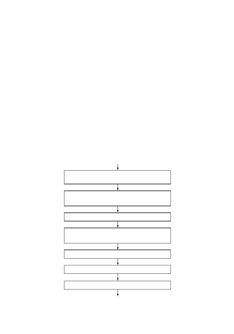
steps in the thermopressing process are shown in
Figure 6.5.
PU waste
Dismantling
sorting, shredding
metal removal
Granulating
Preheating
(7min at 200
°
C)
Mold filling
Pressing
(750 bar, 190
°
C, 1.5min)
Removal of molded parts
Polishing, testing, packing
FIGURE 6.5
Reprocessing of polyurethane waste by
thermopressing. (After Mu¨ller, P. and Reiss, R., Die
Makromol. Chem., Macromol. Symp., 57, 175, 1992.
With permission.)
Recycling of Polymers
6-15
q
2006 by Taylor & Francis Group, LLC
The molded parts obtained by thermopressing of granulated PU waste exhibit only slight reduction in
hardness and impact strength but significant reduction in elongation at break. The last named property,
for example, drops to about 10% of the original value if painted PU wastes are used. Moreover, because of
the use of granulated feed, the resulting molded parts lack surface smoothness and thus should be used
preferably in those areas where they are not visible. In a passenger car, there are many such parts that are
not subjected to tensile stress but require dimensional and heat stability—properties fulfilled by PU
recycled products. Examples of application are wheelboxes, reserve wheel covers and similar other covers,
mudguard linings, glove boxes, and casings.
6.4.2
Kneader Process
The basic of the kneader recycling process is a thermomechanical degradation of polymer chains to
smaller-size segments. The hard elastic PU is thereby converted into a soft, plastic (unmolten) state,
which is achieved with a kneader temperature of 1508C and additional frictional heating. This leads to
temperatures above 2008C and causes thermal decomposition into a product that is soft at 150–2008C but
becomes brittle at room temperature, enabling it to be crushed to powder in a cold kneader or roller
press. The resulting powder can be easily mixed with a powder form polyisocyanate (e.g., Desmodur TT
or 44 of Bayer) and molded into desired shapes by compression molding at 1508C and 200 bar pressure.
The scheme of the recycling process is shown in Figure 6.6.
Partial breakdown of PU network in the kneader results in highly branched molecules with many
functional groups necessitating addition of polyisocyanate in relatively high concentration for
PU waste
Dismantling, sorting,
shredding, metal removal
Thermomechanical decomposition
in kneader (18 min at 150
°
C)
Cooling and crushing
Mixing with polyisocyanate powder in
kneader (5 min at 50–70
°
C). Mold filling
Pressing (200bar, 150
°
C, 10 min)
Removal of molded part
Polishing, testing, packaging
FIGURE 6.6
Recycling of polyurethane waste via partial decomposition in kneader. (After Mu¨ller, P. and Reiss, R.,
Die Makromol. Chem., Macromol. Symp., 57, 175, 1992. With permission.)
6-16
Plastics Technology Handbook
q
2006 by Taylor & Francis Group, LLC

subsequent cross-linking to produce molded articles. The process thus yields products of high hardness
(with Shore up to 80) and high tensile strength (30 MPa), but small elongation at break (6–8%).
6.4.3
Hydrolysis
Hydrolysis of PU waste results in the formation of polyethers and polyamines that can be used as starting
materials for producing foam. In this process, powdered PU waste is reacted with superheated steam at
160–1908C and the polymer gets converted in about 15 min to a liquid heavier than water. The liquid is a
mixture of toluene diamine and propylene oxide (polyether diol), the former accounting for 65–85% of
the theoretical yield:
R
−
NH—C
−
OR
′
R
′
OH
RNH
2
+ CO
2
+
+H
2
O
O
ð6
:4Þ
The recovered polyether can be used in formulations for making PU foam, preferably in admixture
with virgin polyether [47].
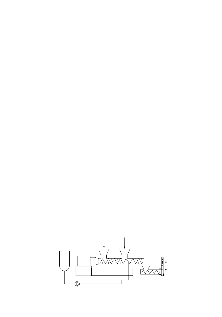
A continuous hydrolysis reactor utilizing a twin-screw extruder has been designed [47] that can be
heated to a temperature of 3008C and has a provision for injection of water into the extruder at a point
where the scrap is almost in the pulp state. Polyurethane scrap in powder form is fed into the extruder
and residence time is adjusted to 5–30 min. Separation of the two components, polyether and diamine, in
the product may be effected by fractional distillation, by extraction with a suitable solvent, or by chemical
means. The PU foams made from these recycled products can be used in several applications, one
example being protection boards for construction sites. Hydrolytic recycling has not, however, found
much application, since virgin raw materials are cheaper than the regenerated products.
6.4.3.1
Glycolysis
Extensive studies have been made on glycolytic degradation of PU wastes. In a glycolytic process,
powdered PU waste is suspended in a short-chain glycol and hated to a temperature of 185–2108C in
nitrogen atmosphere. The glycolysis reaction takes place by way of transesterification of carbonate groups
in PU (Figure 6.7). The reaction product is
predominantly a mixture of glycols and does not
need any further separation of the components,
unlike in the hydrolytic process. The cost of
producing such recycled polyol is reported to be
low enough to make the process economically
viable [47].
The mixed polyols resulting from glycolytic
degradation of PU waste is suitable mainly for
the production of hard foam, such as insulating
foam for houses.
6.4.3.2
Ammonolysis
Chemical recycling of polyurethanes by ammono-
lytic cleavage of urethane and urea bonds under
supercritical conditions has been described [48]. It
is well known that a number of low-boiling
materials give enhance solubility and reactivity
under supercritical conditions. Ammonia has a
critical
point
at
132.458C
and
112.8 bar
(11.28 MPa) with a density of 0.235 g/cm
3
. Being
able to act as hydrogen-bond donor and acceptor, it
provides good solubility for polyurethanes and
O
O
R
1
−
O
−
C
−
HN
−
R
2
−
NH
−
C
−
O
−
R
1
O
O
R
1
−
O C
−
HN
−
R
2
−
NH
−
C O
−
R
1
HO
−
R
3
−
OH
HO
−
R
3
−
OH
Polyurethane
Diol
Mixed polyols
+
+
H O
O
−
H
R
3
O
H
−
O
R
3
H
FIGURE 6.7
Alcoholysis of polyurethane (PU) waste.
By the action of small-chain alcohols (e.g., diol), PU is
decomposed yielding homogeneous, liquid, and mixed
polyols.
Recycling of Polymers
6-17
q
2006 by Taylor & Francis Group, LLC
dissolves their hard segment domains thus enabling a homogeneous reaction. Ammonia is also a reagent
having greater nucleophilicity than, for example, water or glycol is; since it is added in a huge molar excess
compared to the urethane or urea groups of the materials to be cleaved, the equilibrium is shifted towards
the ammonolysis products. The stoichiometry of ammonolysis reaction of a polyetherurethane is shown in
Figure 6.8.
The typical reaction parameters of an ammonolysis process are temperature of 1398C, pressure of
140 bar, and reaction time of 120 min. The ammonolysis reaction transforms derivatives of carbonic acid
–
+ 20 NH
3
O
O
O
O
O
4
O
O
O
N
H
N
H
H
N
H
N
5
+ 4
+ 10
HO
OH
+ HO
NH
2
O
H
2
N
H
2
N
NH
2
FIGURE 6.8
Stoichiometry of ammonolysis reaction of a polyetherurethane. (After Lentz, H. and Mormann, W.
1992. Die Makromol. Chem., Macromol. Symp., 57, 305.)
Ammonia
Polyurethane
1. Ammonolysis
+ extraction
2. Extraction
(water)
Aq solution
of urea
Residue: Amine +
chain extender
Separation
of diol
Phosgenation
of amine
Diisocyanate
Diol
(chain extender)
Residue
polyetherpolyol
Extract
FIGURE 6.9
Flow scheme of a chemical recycling process based on ammonolytic cleavage and separation of polyol
by supercritical ammonia. (After Lentz, H. and Mormann, W., Die Makromol. Chem., Macromol. Symp., 57, 305,
1992. With permission.)
6-18
Plastics Technology Handbook
q
2006 by Taylor & Francis Group, LLC

into urea. Ether bonds as well as hydroxy groups are inert towards ammonia under the reaction
conditions applied. Hydroxy compounds like polyols and diol chain extenders that do not contain ester
groups are recovered as such. The CaO fragments of urethane and urea functional groups are converted
to unsubstituted urea.
After ammonolysis, ammonia is evaporated and can be reused after liquefaction, while degradation
products of polyurethane hard segments (e.g., amines and chain extenders) and urea are removed by
extraction. The pure polyol is left in the reactor. It can be removed mechanically or by extraction with
liquid ammonia in which it is soluble. The recovered amines can be converted to the corresponding
isocyanates and can be reused, along with polyols, in the same applications as before. A flow scheme of
the recycling process is shown in
Among the various material recycling methods for PU scrap and wastes described above, the
thermopressing and kneading processes are especially significant, because these simple processes
render the recycling of cross-linked PU products equivalent to that of thermoplastic products. Lack of
surface smoothness and some reduction in mechanical properties are to be tolerated, especially when
painted PU wastes are recycled. However, good values of E-modulus, structural rigidity, and hot and cold
impact resistance permit use of the molded components of recycled PU in many applications, e.g., in
unsighted parts of automobiles, instruments, and machineries.
6.5
Recycling of Poly (Vinyl Chloride)
Aside from the polyolefins, poly (vinyl chloride) (PVC) [49] and some other chlorine-containing
polymers belong to the most widely applied thermo-plastic materials. There are many applications of
rigid and plasticized PVC. In the building sector, for example, very large amounts are used for pipes,
profiles for windows, floor coverings, roofing sheets and so on. By the end of the lifetime of these articles,
large amounts of scrap have been produced. It is of economic and environmental interest to recycle this
PVC waste as much as possible. Disposal of PVC waste by incineration has its special problems. Due to
the high chlorine content of PVC, its incineration yields large amounts of HCl gas in addition to the
possibility of formation of toxic dioxines and furans. On the other hand, it is a great advantage that many
sources produce large amounts of PVC scrap of the same origin and with similar composition, which
simplifies the reuse possibilities from a logistic point of view.
Dealing with post-consumer mixed PVC waste involves special considerations. Reprocessing PVC-
containing plastics waste without separation will normally entail dealing with mixtures in which large
proportions of polyolefins (mainly polyethylene) are present. In view of the poor compatibility of
polyolefins with PVC, this is not a particularly attractive practical proposition, with respect to processing
and the resulting product. Selective reclamation, i.e., separation from waste mixtures with other plastics,
and subsequent reprocessing are complicated by the wide variety of PVC formulations, and the increased
susceptibility to heat degradation in reprocessing. The main factors in the latter are the heat history
already acquired; the possible presence of polymer already partly degraded in the course of past heat
treatments and/or service; and the remaining stability of PVC articles before their recycling, which often
necessitates an additional stabilization by addition of heat stabilizers. Moreover, about 1/3 of the used
PVC is plasticized by various types of plasticizers. Therefore, for the recycling of such PVC types the
concentration of plasticizers should be known. Due to these considerations, it is important to have rather
detailed information about a PVC scrap before use.
6.5.1
Characterization of Used PVC
Since several chemical reactions occur during processing and use of PVC, which can change the
properties of the polymer, it is necessary to characterize PVC scrap before deciding about the reusability.
Under the influence of heat and light (and also oxygen), PVC chains can be degraded or even cross-
linked, which results in changes in the molecular weight and distribution and thus in the mechanical
properties of PVC. For determining the molecular weight distribution, gel permeation chromatography
Recycling of Polymers
6-19
q
2006 by Taylor & Francis Group, LLC
is the most applied method, but in many cases the measurement of solution viscosity after separation of
all insoluble components, including cross-linked PVC, will suffice.
Because practically no PVC is processed and used without the addition of stabilizers, one should know
the residual stability of a used PVC product. For this the best way may be the determination of the
hydrogen chloride elimination at 1808C under air or nitrogen [50]. The conversion-time curves so
obtained provide indication of the residual stability from the induction period and also enable
calculation of the rate of HCl split-off after consumption of the stabilizers. In some cases, however, it
may be sufficient to use a simple Congo Red test (e.g., according to DIN 53 418) instead of the apparatus
for measuring the HCl elimination.
The dehydrochlorination of PVC results in the formation of polyene sequence that can be responsible
for discoloration and also act as starting sites for further degradation and cross-linking reactions. For
some applications it may thus be useful to have some knowledge about the unsaturated structures that
have been formed in PVC during the use. For this purpose, the investigation of the UV-VIS spectra that
give at least semiquantitative information about the dehydrochlorination and the application of
ozonolysis [51], which results in cleavage of the unsaturated sequences in PVC, may be useful.
In the case of reuse of plasticized PVC, it is important to determine the residual plasticizer content.
This can be obtained by extraction with ether or similar nonsolvents for PVC and determination of the
chemical nature of the plasticizers by thin-layer or gas chromatographic methods. The determination of
the glass transition temperature by differential thermal analysis also gives information on the efficiency of
the residual plasticizers.
6.5.2
In-Line PVC Scrap
Normal recirculation, in the same process, of the clean PVC scrap generated (e.g., edge trim in
calendering) is widely practiced, in particular with PVC for noncritical applications. General PVC
scrap, both from internal and external sources, is also converted by some processors into such products as
cheap garden hose or core composition for cables.
Two possibilities have been investigated for the recycling of die-cutting scrap produced in the
processing of PVC sheet: production of secondary sheet and production of extruded profiles or pipes.
First the scrap is ground up in a grinding mill. The stabilizer used in the original process is added again in
a premixer, and pigments are often added to achieve a uniform, desired color. This premix is fed into the
compounding unit.
If the regrind includes rigid, semirigid, and plasticized PVC, the rigid and semirigid fractions can be
charged into the compounding unit through a first-inlet opening and plasticated in an initial kneading
zone. The plasticized PVC scrap is then fed into this fluxed stock, which ensures the gentlest and most
homogeneous processing (Figure 6.10). Any additional plasticizer required is injected directly into the
Plasticizer
Rigid PVC
scrap
Plasticized
PVC scrap
Strainer
FIGURE 6.10
Recycling of PVC film scrap.
6-20
Plastics Technology Handbook
q
2006 by Taylor & Francis Group, LLC
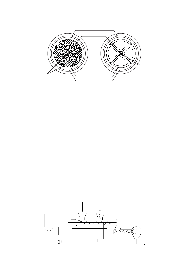
kneading zone of the compounding unit by a pump. This is done because the plasticizer cannot diffuse in
the PVC regrind within a reasonable time, which it can in the case of virgin PVC. It is advisable to use a
strainer in order to remove any contamination from the stock. Afterwards, the calendering process is
carried out as usual.
For the production of profiles and pipes, the homogeneous stock is pelletized following compounding.
The pellets are fed to an extrusion line.
In the cable sector, compounders are often confronted with the problem of recycling copperless
insulation and sheathing scrap. An approach that may be taken in this case is to use this scrap for
producing filling core mixtures. The purpose of the filling cores is to fill out the cavities between a cable’s
conductors (Figure 6.11). Since their composition is not subject to any special electrical or mechanical
specifications, it is normally made as inexpensive as possible, usually receiving a high level of chalk filler.
The PVC in this case acts mainly as binder for the filler. For compounding such cable filler cores, the
reground PVC scrap, with a particle size of 5–10 mm, is fed into the first inlet of a compounding unit
designed specifically for this application (Figure 6.12). The reground scrap is plasticated homogeneously
in the first kneader zone, enabling it to absorb the high filler loading fed into the second inlet opening
without any difficulty. For increased flexibility of the filler cores, plasticizer may be injected into the
kneading chamber by a pump (see Figure 6.12). The homogenized stock is pelletized following
compounding.
Outer sheathing
Insulation
Inner sheathing
Reinforcement
Filler
profiles
Filler
profile
FIGURE 6.11
Schematic of cable design.
Plasticizer
Reground
PVC scrap
Filter
Pelletizer
FIGURE 6.12
Compounding of cable filler cores.
Recycling of Polymers
6-21
q
2006 by Taylor & Francis Group, LLC

6.5.3
PVC Floor Coverings
PVC floor coverings are a combination of a number of constituents that together comprise the recipe for
a floor covering. Typical floor covering recipes are for the most part made up as follows: PVC 28–50%,
plasticizer 10–20%, stabilizers 0.5–1%, slip agents less than 1%, filler 25–60%, and pigments 1–5%.
Further, many floor coverings are provided with additional textile- or glass-fiber—containing carrier
layers. Given an average service life of 10–17 years, old PVC coverings represent a large reserve of
raw materials.
To exploit these large reserves of raw materials on an industrial scale, one needs a network for
systematic collection of old coverings, a system of transport logistics, and the ability to build technically
feasible recycling plants. In order to undertake this work in Europe, about 20 producers of PVC raw
material and floor coverings from Germany and other European countries joined together in April 1990
to form the Society for the Recycling of PVC Floorings.
The main operations carried out in a recycling plant for old PVC floor coverings are sorting, cleaning,
shredding, purifying, powdering, mixing, and packaging [52]. The purification unit essentially
comprises a hammer mill and a downstream vibrating screen. The function of the hammer mill is to
knock off any residues of screed or adhesive still adhering to the floor covering, and the vibrating screen
then separates off these residues. The shredding material that has been purified in this way is first passed
to a cutting mill, which enables it to be precomminuted to granules that are first homogenized in a
mixing silo and purified by means of zigzag sifters before being processed to PVC floor covering powder
in the powder mill. The powder can be upgraded by the addition of plasticizer, PVC, or filler to give
powder recipes suitable for calendering to make new floor coverings; this depends on the quality of the
batch in question. Other possible uses of the powder are for products, such as mats for cars, mud flaps,
and soft profiles.
6.5.4
PVC Roofing Sheets
A major use of PVC in the building industry is for roofing sheets. These sheets are produced on calenders
and contain in most cases two plasticized PVC foils that are reinforced by glass fiber or polyester fabrics.
The used sheets show different properties, depending on whether they are applied under direct influence
of light and weather conditions and on the fact that in some cases these sheets on the roof are loaded with
gravel or coarse sand.
After a lifetime of 10–20 years, the roofing sheets have to be replaced by new ones, which is normally
done by the same firm(s). Therefore, the recycling of used roofing sheets is rather easy from the logistic
point of view and has been common practice for many years. New PVC roofing sheets may contain up to
10% of the recycled material [52].
6.5.5
Post-Consumer PVC
Some post-consumer PVC sources are water, food, pharmaceutical, and cosmetic bottles, and film.
Another significant source of post-consumer PVC is used electric cable, coming principally from plant
demolition and, to a lesser degree, from manufacturing scrap and offcuts.
Most end-use markets for recycled plastic bottles require that they be separated by resin type and color.
This ensures high end-use value for new products incorporating substantial amounts of the recycled
resin. PVC bottles, like PET bottles, are very recyclable. Manual sorting of nonpigmented PVC and clear
PET bottles is difficult because they look alike. When the two types are received commingled, the
reprocessor can experience quality deficiencies due to rheological incompatibilities between these two
resins. Therefore, all attempts to separate and remove these two resins must be made prior to recycling.
Manual sorting techniques are inadequate to meet the market’s needed quality standards, so new
techniques have been engineered that will detect and separate bottles made from either of these
two resins. A simple device senses the presence of chlorine atoms as a means to detect PVC bottles.
6-22
Plastics Technology Handbook
q
2006 by Taylor & Francis Group, LLC

Once detected, PVC bottles are pneumatically jettisoned from the commingled bottle feed-stream by a
microprocessor-based air-blast system.
The step after sorting is baling or granulation. Granulation is the preferred method of intermediate
processing since the material so processed commands the highest market value. For upgradation of the
resin from the recycled PVC bottles, several steps are explored depending on the results of
characterization tests as discussed earlier. These include incorporation of virgin resin (10–90%),
restabilization against UV and heat, and incorporation of processing aids, impact modifiers, lubricants,
plasticizers, and antioxidants.
The recovery of electric cable is long established because of its valuable copper content. After this
conductor material has been extracted, the residue consists of sheathing and insulation that may contain
rubber and polyethylene as well as PVC. These other materials can be largely removed from grinding, by
flotation, vibration, and filtration, but rubber is especially difficult to remove entirely, so that applications
for material recycled from cables containing it are limited to areas such as car mats and carpet underlay.
6.6
Recycling of Cured Epoxies
Thermosetting plastics are difficult to dispose because of their network structure. Chemical recycling is a
promising route for converting these plastic wastes by returning them back to their original constituents.
However, thermosetting resins are usually reinforced by reinforcement such as glass fiber to modify their
brittleness and increase their strength, forming composite materials with complex structure. The
presence of reinforcement in the cured composite thus makes the recycling of the matrix resin
more difficult.
An approach to chemical recycling of amine cured epoxies using nitric acid solution has been
proposed [53,54]. In order to investigate the practical applicability of the proposed research, glass fiber-
reinforced bisphenol F type epoxy resin (cured with 4,4
0
-diaminodiphenylmethane) was decomposed in
nitric acid solution and the decomposed organic products as well as the fiber were recovered. In a typical
experiment, the glass-reinforced epoxy composite was cut into small pieces and kept immersed in 4 M
nitric acid at 808C till the matrix resin dissolved completely, yielding a yellow solution and leaving behind
the inorganic (glass) residue which was separated and recovered. When the yellow solution was cooled in
ice no crystal was formed. However, if nitric acid solution of higher concentration, such as 6 M, was used
for immersion, crystals separated out because of breakage of the main chain of epoxy resin and
subsequent nitration under the attack of nitric acid [55].
The yellow solution was subjected to neutralization with sodium carbonate, extraction, refinement,
and drying to obtain neutralized extract (NE) whic was then repolymerized to prepare the recycled resin.
Since NE could contribute hydroxyl groups to bond with phthalic anhydride (curing agent), it was
employed to substitute a part of epoxy resin. The proportions of NE addition ranged from 5 to 30 wt%
(the ratio of weight of NE to the total weight of NE and epoxy resin). The process of neutralization and
refinement of the acid extract is presented in
6.7
Recycling of Mixed Plastics Waste
Commingled plastics currently represent an estimated two-thirds of today’s recycled plastics streams.
That fraction can be expected to shrink somewhat with the development of more successful identification
and segregation technologies in the future. However, commingled plastics streams will continue to make
up a significant volume for several reasons: proliferation of grades and types of commodity; profusion of
polymer blends and alloys; contamination of recycle plastic parts with metals, coatings, and laminates;
and practical cost considerations. Mixed plastics wastes can be divided into two groups depending
on their source: mixed plastics from household or municipal solid wastes and plastics from
industrial sectors.
Recycling of Polymers
6-23
q
2006 by Taylor & Francis Group, LLC
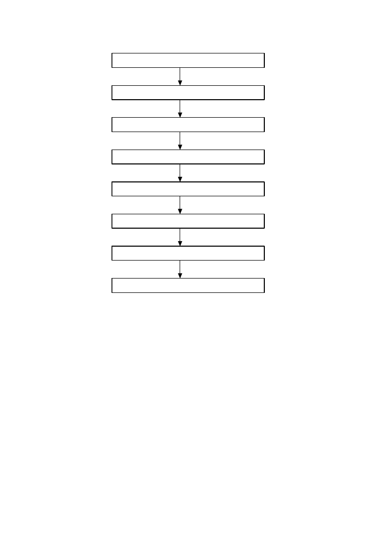
The first category (post-consumer mixed plastics) involves the articles that are used in food,
pharmaceutical and detergent packaging, shopping, and others. The majority of these are composed
of films, sheeting, strapping, thermoformed trays, as well as a variety of bottles for soft drinks, food, and
cosmetics. There are mainly five different polymers—PE, PP, PS, PVC, and PET—that contribute to the
total amount of plastics waste. The composition of mixed plastics can change depending on the regional
habits and the seasons of the year. Also the mode of waste collection can influence its final composition.
The category of postindustrial wastes concerns articles like the products of the car, furniture, and
appliances industries. The problems of these sectors is a wide variety of engineering materials and a high
number of components employed to build a final system.
6.7.1
Direct Reuse
A direct solution to the problem of plastics disposal can be the reuse of a heterogeneous mixture of
plastics directly obtained from an urban collection. Today there are extruders specifically designed for
reprocessing post-consumer and postindustrial waste materials. The waste material can have many forms
and can range in bulk density from approximately 1 to 35 lb/cu ft. The form, bulk density, moisture
content, contamination level, and process-temperature restrictions all affect the design of the extruder to
be used. For example, due to the presence of PVC resin, the melting temperature must be kept below
2108C and the barrel residence time must not exceed 6 min. Furthermore, in the mixture, the relatively
high content of semicrystalline polymers like PET, whose melting point is above the processing
Yellow solution after resin is dissolved in HNO
3
Extracting with ethyl acetate
Extract solution in ethyl acetate
Adding sodium carbonate solution
Neutralized extract solution (two phases)
Separating
Neutralized solution in ethyl acetate
Removing solvent
drying
Neutralized solid mixture
Adding ethyl acetate
Extract solution in ethyl acetate and solid compound
Filtering
Neutralized solution in ethyl acetate
Removing solvent
drying
Neutralized extract (NE)
FIGURE 6.13
Process of extraction of epoxy resin dissolved in nitric acid and neutralization of the extract. (After
Dang, W., Kubouchi, M., Sembokuya, H., and Tsuda, K., Polymer, 46, 1905, 2005. With permission.)
6-24
Plastics Technology Handbook
q
2006 by Taylor & Francis Group, LLC

temperature, influences the extruder design or the final properties of the manufactured product. Large
injection gates and mold channels must be used in order to avoid undesirable occlusions in the channels.
Standard single-screw extruders are no longer adequate to recycle or reclaim this wide range of
materials in a cost-effective manner. There are now special extruders designed to process the lighter-
bulk-density materials. Low-bulk-density materials are the various forms of film, fibers, and foams
commonly used in the packaging industry. Due to their low-bulk density, such materials typically
require an auxiliary device to facilitate proper feeding into the extruder throat. There are several
varieties of such feeding mechanisms available [56]. Two of them are a rotating screw-type crammer
and a piston-type ram. The crammer and ram systems both act on the same principle; that is, an
auxiliary feeding device is used to convey and to compact the low-bulk-density materials into the feed
section of the extruder screw.
The screw-crammer system uses a conical hopper with a screw that is driven by a separate gear
reducer and variable-speed drive motor. The output and effectiveness of the crammer are determined
by the screw configuration and the available speed. The ram-type system, on the other hand, uses a
pneumatic ram to stuff material into the screw. The ram is a piston-driven unit with the stroke
timing adjustable by setting a series of timers located in the control panel. The feed section used by
the ram system has an opening that is 12–14 times larger than that of a standard screw extruder.
This allows low-bulk-density material to flow freely into the feed throat where the ram can compress
it into the screw. Depending on the extruder size, the ram can compact materials with a force of
2000–9000 psi.
Feed materials usually need to be supplied to either the crammer or the ram system in a chopped form.
The size and bulk density of the chopped particles affect the performance of the crammer and ram, and
thus ultimately the output of the extruder. Both these systems can also be used to process higher-bulk-
density products.
A third method of processing low-bulk-density materials is through the use of a dual-diameter
extruder [56]. This system has two distinct sections: a large diameter feed and a small diameter
processing section. The large-diameter section acts as a cramming device—compacting, compressing,
and conveying the feed material—while the smaller-diameter section is used to melt, devolatilize, and
pump the extrudate into a die. In the feed section, the screw can have deep flights, allowing low-bulk-
density materials to flow freely, while in the processing section the screw resembles that of a typical
extruder. The screw is available in one of several configuration: single-stage, two-stage, or barrier design.
Depending on process needs, these designs optimize output and raise product quality.
The feed section of a dual-diameter extruder can be equipped with feed-assist components that in
some cases work in conjunction with specially designed screws to allow processing of a wide variety of
feedstocks that are fed to the machines in roll form. Among these possible feedstocks are loose bags,
handle cutouts from bag making operations, and continuous web products such as blown and cast film
scrap. This ability eliminates the cost of shredding, grinding, and densification of many materials. A
dual-diameter extruder is also capable of processing materials with a high-bulk density. The crammer,
ram, and dual-diameter systems do not differ widely in equipment costs, or production rates.
It is well established that a strong incompatibility is typical of polymers usually found in commingled
waste (PE, PP, PET, PVC, and PS). This incompatibility gives rise to materials that have inferior
mechanical properties, particularly with regard to tensile, flexural, and impact strengths. This means a
strong limitation of applications, in particular in the case of thin walls and manufactured products that
have to work under flexural and tensile stresses. However, by adding to the mixture specific components
like other polymers from homogeneous recycling, fillers (talc), fibers, or promoters (compatibilizers)
that increase the compatibility, it is possible to improve the tenacity or stiffness, product aesthetics,
and processability.
Addition of glass fibers, for example, is found [57] to yield products with very high stiffness (e.g.,
elastic modulus Ex2800 MPa with 30% glass fiber), higher than that with talc (Ex1250 MPa with 20%
talc) and far better than that of the original mixture (Ex950 MPa). Addition of LDPE and styrene-
butadiene-styrene copolymer, on the other hand, improves the tenacity (showing, typically, a 30–90%
Recycling of Polymers
6-25
q
2006 by Taylor & Francis Group, LLC
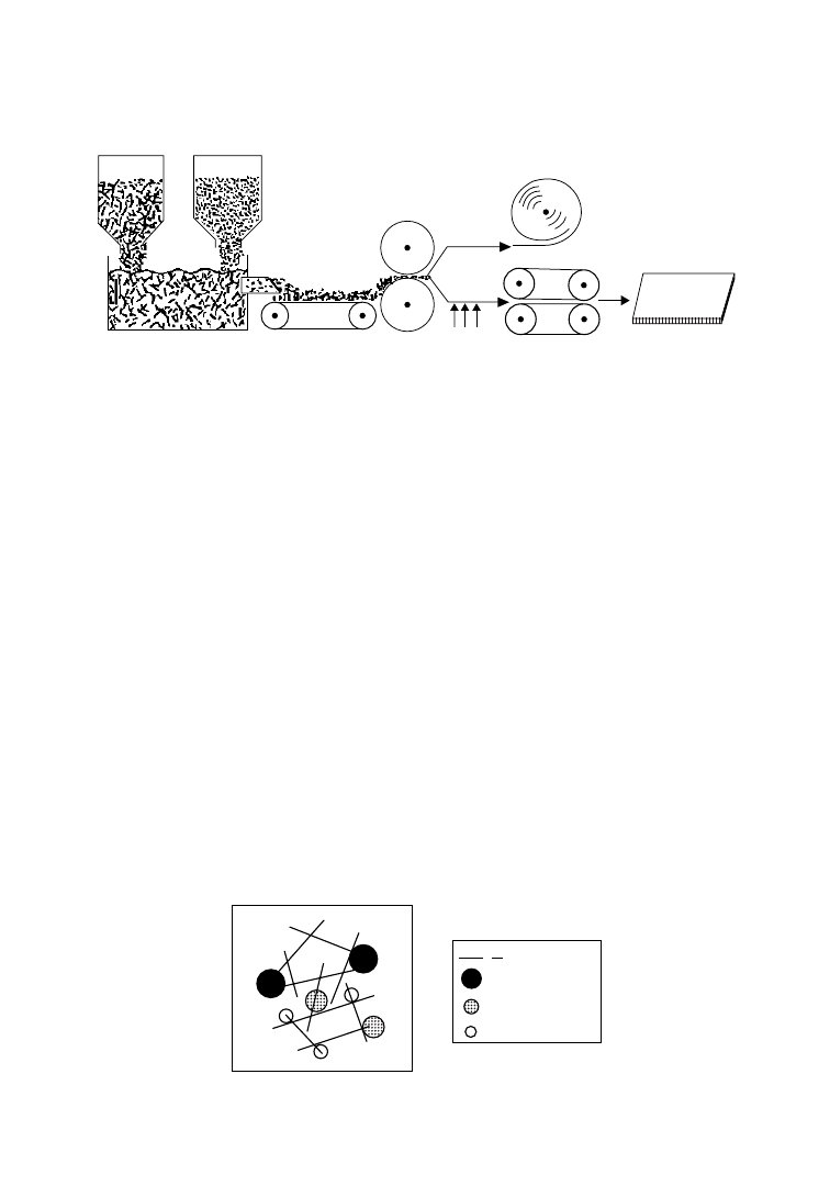
increase in elongation at break). Extruded profiles have thus been made that can be employed to build
benches, garden tables, bicycle racks, fences, and playing facilities for park. Coextrusion technology can
be used very effectively to improve surface properties like puncture, impact and weather resistance, as
well as appearance. One interesting application for mixed plastics, because of their large market volume,
is the production of injected tiles for paving [57].
A new and exciting technology has been developed in the fabrication of composite materials made
with commingled plastics. It followed the discovery in 1986 by the scientists and technologists at GE
Plastics that useful products could be fabricated using Radlite technology (Figure 6.14) if the powdered
feed consisted of two or more resins. While compatibilization of dissimilar resins is typically brought
about by chemical means, this is not the case with Radlite technology products where compatibilization
appears to take place by physical means, i.e., the binding of dissimilar resin domains through the fibers.
A conceptual model of physical compatibilization is shown in Figure 6.15.
The rolls or sheets made by Radlite technology using commingled plastics and chopped glass fibers
(0.25–1.0 in.) can be converted to finished parts by conventional forming technologies such as
compression molding (typically 200–2908C, 3–5 MPa, 2–4 min). These are fully consolidated, essentially
void-free products with specific gravities that would be calculated on the basis of resin type and glass fiber
content. The physical properties of the consolidated structures from commingled plastics are in general
similar to standard grades of SMC composites.
Foamed network structures (lofted structures) are also prepared in a compression press using Radlite
technology. In this case, after applying full temperature and pressure for the requisite 2–4 min, the platen
gap is opened 1.5 times the original setting (for primarily open-cell structure) or 1.1–1.2 times the
Chopped
glass
Polymer
powder
Aqueous
dispersion
Drain belt
Belt
press
Mat
roll
Composite
sheet
Heat
Compaction
FIGURE 6.14
Schematic of Radlite technology.
1"
2 Glass fibers
Polymer 1
Polymer 2
Polymer 3
FIGURE 6.15
Conceptual model of physical compatibilization.
6-26
Plastics Technology Handbook
q
2006 by Taylor & Francis Group, LLC

original setting (for primarily closed-cell structure). Foamed structures have the aesthetic and physical
appearance of particle board, a common material of construction. Application possibilities of products
made by the Radlite technology include highway signs and sound barriers, substructures for bathtubs and
shower stalls, pallets and tote boxes, and flooring products and building fascias.
A novel application of mixed plastics is to toughen road surfaces. In 1986, the Ragusa Laboratories of
ECP Enichem Polimeri in Italy investigated the use of mixed plastics waste to reinforce bitumen. Sorted
municipal waste with a polyethylene content of approximately 60% was mixed with bitumen in varying
proportions up to 20%. The properties of the resultant bituminous concrete were improved in two
important ways: better wear resistance and raised softening point. Use of bitumen modified with mixed
plastics waste of high polyethylene content as an experimental road surface under heavy traffic has
established its notable superiority over unmodified bitumen for road surfacing.
6.7.2
Homogeneous Fractions
A widespread solution, in terms of application and market volume, could be the recycling of single
materials or homogeneous fractions obtained from a separation process of the mixture. In fact, the
samples obtained from single homogeneous fractions show a general performance far greater than that of
samples produced from mixed plastics. Separation of post-consumer mixed plastics (municipal waste)
into four fractions—polyolefins (PO), PS, PVC, and PET—is commonly adequate.
The improvement of tenacity is, in particular, evident when considering impact resistance of PO as
compared to mixed plastics. Samples subjected to impact tests show an increase in elongation at the
breaking point from 7% to above 100% [58]. The samples of recycled PVC fraction are comparable with
those of a common virgin, with only marginal reduction in mechanical properties.
With regard to PET fraction, the potential applications are strongly dependent on its purity (as
discussed earlier). Applications like films, fibers, or straps are not recommended when a high
concentration of impurities are present. In this case, the PET fraction can be employed for structural
applications as an engineering polymer with the addition of other components like glass fibers, impact
modifiers, and/or nucleating systems. However, reuse of the PET fraction implies that the amount of
residual PVC must be kept below 50 ppm to avoid undesirable polymer degradation that results in poor
surface appearance and loss of mechanical properties of the manufactured products.
Mixed waste consisting of PET and PE can be converted into useful products using compatibilizers
such as LDPE and LLDPE with acid and anhydride groups grafted on the backbone. A range of products
can be made with such compatibilized blend, e.g., office partitions, roofing, slates for benches and chairs,
and generally any extruded or molded sections needing mechanical load-bearing capacity similar to
aforesaid applications.
With advances in cleaning, sorting, and other recycling technologies, more products with recycled
plastics content are being manufactured. Some recent developments include using recycled PP and
HDPE to produce a wide range of products. For example, multimaterial PP bottle scrap (typically,
90% PP, 5% ethylene-vinyl alcohol barrier resin, and 5% olefin adhesive) can be added in varying
amount (3–12%) to recycled HDPE and processed on a single-screw extruder to form pellets for
compression molding to a range of products. The multimaterial resin can also be sandwiched between
two layers of virgin HDPE using a three-layer extrusion blow-molding process. Bottles made in this
way from 75% virgin resin and 25% post-consumer blend are found to be suitable for normal
commercial trade [59].
6.7.3
Liquefaction of Mixed Plastics
There have been many research activities on plastics liquefaction because oil is easy to store, transport,
and use. Most promising among them is the liquefaction technology jointly developed by the Japanese
Government Industrial Development Laboratory (Hokkaido), Mobil Oil Corporation, and Fuji Recycle
[60]. The process features a combination of thermal and catalytic cracking using a proprietary Mobil
Recycling of Polymers
6-27
q
2006 by Taylor & Francis Group, LLC

ZSM-5 catalyst. It can treat polyolefinic plastics, PE, PP, PS, or their mixtures, producing relatively low
pour and highly aromatic liquid at a yield of about 85%. The produced oil contains many aromatics
including benzene, toluene, and xylene.
Waste plastics are crushed, washed, and separated from other plastics that cannot be liquefied (e.g.,
PVC) by utilizing the difference of specific gravities against water. Plastics that can be liquefied mostly
float in water while plastics that contain a lot of chlorine, carbon, and oxygen have high specific gravities
and sink in water. However, some PVC floats and is recovered with PE or PP. Therefore, after separating,
the feedstock for liquefaction may still contain 3–7% PVC. Fuji Recycle has developed liquefaction
technology to treat such PVC contaminated mixtures [60].
For liquefaction, polyolefinic plastics are warmed to about 2508C, melted and transferred to the
melting vessel by a heated extruder. In the melting vessel, plastics are further heated to about 3008C by
heat transfer oil and transferred to the thermal cracking vessel. In the thermal cracking vessel, melted
plastics are hated to about 4008C by the cracking furnace. The thermally cracked gas phase hydrocarbon
passes through the catalytic reactor containing ZSM-5, where it is cracked and converted to higher-value
hydrocarbon. The recovered liquid and gas are separated by cooling and the gas is used as in-house fuel.
Because of the pore structure of ZSM-5, the produced hydrocarbons are composed of low molecular
species (4 carbons to about 20) which are in the gasoline, kerosene, and gas oil boiling range. In
comparison, the carbon numbers of hydrocarbons produced only by thermal cracking range from 4 to
44. Polystyrene in the feedstock enhances the yield of ethylbenzene, toluene, and benzene, while
producing gas that is predominantly propane/propylene.
6.8
Post-Consumer Polyethylene Films
Driven by consumer and legislative pressures, post-consumer film recycling has gained momentum and
is now one of the fastest-growing segments of the recycling industry. post-consumer films consisting of
LDPE, LLDPE, and HDPE, which are accounted for mostly by grocery sacks, stretch and shrink wrap,
agricultural film, packaging, and blow-molding drums, and have thicknesses ranging from 0.2 to 5.0 mils.
Film recycling was first developed in Europe for agricultural film, which is relatively easy to process due
to its high-bulk density and minimal contamination. Today, interest in recycling systems for film of
varying thickness and resin types has changed the design of a recycling line to one that uses both high and
low-bulk-density material.
The primary challenge to recycling film is contamination. According to an industry estimate, up to
25% of all grocery bags are contaminated and require very thorough washing in the recycling process.
A typical route for recycling plastic bags is shown in Figure 6.16.
Bales weighing 600–800 lb, collected by commercial haulers, film-generating business, or the solid-
wastes-handling industry, are first fed into a breaker-shredder. The shredded material then passes over a
vibratory conveyor or through metal-detection systems to remove ferrous and nonferrous contaminants.
Film is next sent to a sedimentation tank for removal of rocks or dirt before going into the granulator
Baled
film
Baled breaker-
shredder
Vibratory
conveyor
Sedimentation
tank
Granulator
Packaging
Pelletizer
Drier
Wet separator
Washer (s)
FIGURE 6.16
Typical route for recycling plastic bags.
6-28
Plastics Technology Handbook
q
2006 by Taylor & Francis Group, LLC

(usually wet) for size reduction. Granulated into flake, the material then passes to a hot wash for removal
of glue, residues, and remaining labels. Depending on the feedstock and the extent of contamination, the
film may go through more than one wash cycle.
After the wash, the material moves to the separation stage. Two most common methods for
separating plastics by resin type are float-sink and hydrocyclone. The float-sink method is less costly
but requires a relatively large tank size in order to realize volume effectiveness. A hydrocyclone is more
costly, but uses less water, has no moving parts, and generally takes up less space than the older float-
sink method.
The flaked material from the wet separator, described above, goes through a drying and dewatering
stage to an extruder, where in the melt phase the plastics can be mixed with dyes and other product
enhancements, and then filtered and forced through a die for fabrication of free-flowing pellets.
Depending on the mixture of LLDPE, LDPE, and HDPE, the pellet can be tailored for specific
markets. Low-quality pellets are often sold as a commodity in the general marketplace. High-quality
blends of polyethylene are suitable for many nonfood film applications.
One major market for recycling film is packaging. Many consumer-products companies have already
turned to detergent bottles and other packaging made with significant percentages of recycled HDPE.
Another fast-growing outlet is coextruded blown film used in trash bags, in which post-consumer resin is
sandwiched between virgin layers of high-molecular-weight HDPE. The coextrusion technology allows
high percentages of reprocessed material to be incorporated into virgin resin.
In many countries, legislation is a key driving force behind greater recycling efforts. Several states in the
U.S. have passed recycling content standards mandating that virgin plastics used in some applications,
such as grocery and trash bags, contain a certain percentage of recycled material. In California, for
example, trash bags are required to have 30% recycled post-consumer content. Germany requires that
64% of all packaging materials be recycled. Under the German system, all types of plastics packaging are
collected together and subsequently segregated into several categories: rigid containers; films; cups, trays,
and blister packaging; and foamed material. The materials are then offered back to industry for recycling
purposes at no charge.
6.9
Recycling of Ground Rubber Tires
Discarded tires represent a significant component of the overall plastics recycling challenge. They are an
easily segregated, large volume part of the waste stream and present their own, somewhat unique, waste
recycling problems. Some of the methods of utilizing scrap tires that have been investigated [61–63] are:
burning, pyrolysis, use in cleaning up oil spills, road surfaces, roofing materials, and playground surfaces.
While some of these approaches have been put into practice, the scrap tire disposal problem is clearly a
case where supply far exceeds available use, pointing to the need for new methods of utilization and/or
technological advances to extend the existing ones.
One area that has the potential to utilize large volumes of discarded tires is the need for a filler in
polymer composites. Although the use of ground rubber tire (GRT) as a filler in polymer blends is a
potentially attractive approach, it is fraught with a number of difficulties. Generally, when the large GRT
particles are added to either thermoplastic or thermoset matrices, there is a large drop in mechanical
properties, even at relatively low filler loadings [64]. Since the approach here is to use the GRT as a low-
cost additive, and as there are a number of other materials competing in this regard, overcoming this
large drop in properties has to be accomplished with little added cost (both in terms of additives and
additional processing). This has proven to be quite a challenging task.
In order to be used as a filler in polymer composites, tires are first ground into a fine powder on
the order of 100–400 mm, which is accomplished typically through either cryogenic or ambient grinding.
The large rubber particle size used in GRT composites is reported to be one of the two major
factors (the other being adhesion) contributing to the poor mechanical properties generally observed
for GRT-polymer composites. In general, a low particle size is desired for optimum composite properties.
Recycling of Polymers
6-29
q
2006 by Taylor & Francis Group, LLC

In GRT-polymer composites, however, the particle size is quite large. Since there is very little breakdown
of the particles under normal melt blending conditions due to the highly cross-linked nature of GRT, the
particle size is to be controlled only by the grinding process, which in turn, is influenced by process choice
and economics.
In order for GRT to be used as an economical filler, the particle size has to be kept as large as possible to
minimize grinding costs. Typically, the lower limit on particle size necessary to produce economical
composites lies in the 40–80 mesh (x400K100 mm) range, while for rubber toughening applications it is
generally reported [65] that the optimum particle size for toughening brittle polymers is in the 0.1–5 mm
range. Thus the size gap is large. Though it adds to the cost, there may be some advantage in going to
smaller particle sizes if significant gains in mechanical properties are realized. The detrimental effects of
adding GRT to cured rubbers decreases as the particle size is decreased [66]. For GRT recycled back into
tires, for example, the detrimental effects are almost eliminated [66] with the use of ultrafine
(20 mm) rubber.
As mentioned above, simple addition of GRT to most polymers results, in general, in significant
decreases in mechanical properties due to large particle size and poor adhesion. Although some of these
materials may find limited application in low-level usages, there is clearly a need to improve on the
properties of GRT-polymer composites for them to become a large-volume material. Since lowering
particle size to effect any substantial improvement in material properties adds significantly to grinding
costs, strategies for overcoming the deleterious effects of adding GRT to polymers have focused on
methods of improving adhesion.
The poor adhesion is, at least in part, due to a high degree of cross-linking in the GRT particles. The
highly cross-linked nature of the particles inhibits molecular diffusion across the interface so that there is
little or no interpenetration of the phases, resulting in a sharp interface. There have been a number of
reports of processes that claim to improve properties of GRT-polymer composites through enhancing
adhesion. The use of an aqueous slurry process using a water-soluble initiator system to graft styrene to
GRT has been reported [67]. The styrene-grafted GRT particles are found to be give composites with
properties superior to straight mechanical blends.
Precoating of GRT particles with ethylene/acrylic acid (EAA) copolymer is found to improve the
mechanical property, which is attributed to an interaction (H bonding) between the EAA copolymer and
functional groups on the GRT surface, resulting in increased adhesion [68]. Thus a blend of 40 wt% EAA
coated GRT particles (4 wt% EAA) with LLDPE was shown to have impact and tensile strengths 90% of
those for pure LLDPE, representing increases of 60% and 20%, respectively, over blends with uncoated
particles. The use of maleic anhydride grafted PE (PE-g-MA) resulted in increases in the impact strength
of LLDPE-GRT composites of as much as 43%, without the need for a precoating step [68].
Electronic spectra for chemical analysis (ESCA) of GRT surface reveal an oxygen surface content of 5–
15%, which may indicate the presence of –OH or –COOH functionalities. Since the epoxy group readily
reacts with a wide range of functional groups such as –OH, –COOH, –SH, –NH
2
, the use of ethylene-co-
glycidyl methacrylate (EGM) as a coupling agent [68] has been investigated. A significant increase in
impact behavior has been observed. It is seen that judicious selection of a compatibilizing agent can lead
to composites with quite reasonable mechanical properties at significant levels of GRT (as high as 50–
60 wt%). Because added compatibilizer levels are low (4–7 wt%) and no specialized processing steps are
necessary, these higher-value composites can be produced at little additional cost over simple GRT-
polymer blends.
It has been observed recently [69] that special treatment of GTR by bitumen confers outstanding
mechanical properties on thermoplastic elastomers (TPEs) produced using the treated GTR. Typically
the reclamation of GTR by bitumen is carried out by preheating the GTR/bitumen blend (1/1 by weight)
at 1708C for 4 h in an oven, followed by rolling on mill rolls at about 608C for 40 min. Thus, high
performance TPEs, based on recycled high-density polyethylene, ethylene-propylene-diene monomer
(EPDM) rubber, and GTR treated with bitumen has been prepared. It has been concluded that bitumen
acts as an effective devulcanizing agent in the GTR treatment stage. In the subsequent steps of TPE
6-30
Plastics Technology Handbook
q
2006 by Taylor & Francis Group, LLC
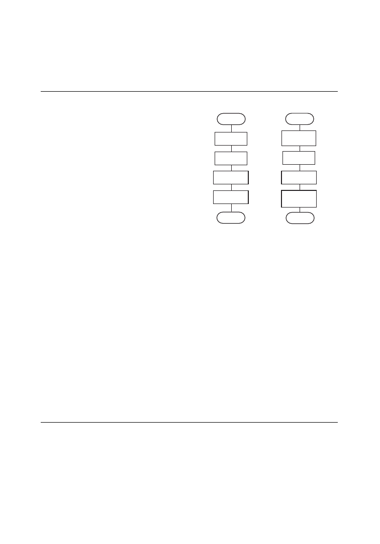
production, bitumen acts simultaneously as a curing agent for the rubber components (EPDM/GTR)
and as compatibilizer for the blend components.
6.10
Recycling of Car Batteries
Polypropylene (PP) is obtained in segregated form
as casing fragments from reprocessing of used
lead-acid batteries from automotive applications.
Because the casing makes up about 7% of the total
battery and the used batteries are recycled
primarily for lead recovery, PP is obtained
without additional cost and in substantial quan-
tities to warrant the operation of a plastics
recycling plant.
In the first step of a typical recycling operation,
the batteries are processed through a crushing and
separation system operating on the TONOLLI
principle (Figure 6.17), which has been success-
fully employed in various battery recycling plants
in Europe and North America. The heavy fraction
(lead, lattice metal) and ebonite are then separated
from the light fraction (PP and impurities). The
PP at this stage has a purity of 97%, which is still
insufficient for its further processing. It is therefore sent to an upgrading stage, where it is further reduced
in size in a wet-type rotary grinder and subsequently separated from water by sedimentation. After
passing through two series-connected driers and a cyclone separator, the PP is available as so-called
regrind with a purity of 99.5%. As the regrind consists of various types of PP differing in their
formulation, molecular composition, and stabilizer content, it has a broad spectrum of characteristics.
Suitable mixing can be done to obtain an intermediate product with a narrowed range of statistically
uniform product characteristics.
In the next step, the regrind is routed to a compounding plant where—with controlled addition of
additives, polymers, and fillers—the feed mix can be adjusted to suit the specific customer requirements.
This feed mix is then metered into a special twin-screw kneader where it melts under the dual action of an
external heater and internal shear forces, producing a homogeneous compound. Volatile matter is vented
and unmolten impurities are filtered out. The melt is subsequently palletized in a melt granulator and the
resulting granulate is quenched in a water bath, centrifuged, and finally passed through a hammer mill to
break up lumps. The end product is a granular secondary raw material and suitable for
injection molding.
6.11
Plastic Recycling Equipment and Machinery
While the plastics recycling activity, driven by consumer and legislative pressures, is all but certain to
increase, the key variables in the rate of growth are the plastics industry’s ability to develop an economical
material-collection infrastructure and to improve the methods for handling and processing of
contaminated scrap. Techniques for selection and recycling of post-consumer plastics are, however,
closely related to the characteristics of plastics containers consumption, which vary greatly according to
the geographical areas and the relevant law regulations governing activities in this sector.
Consumption features play a major role in the choice of the materials to be recycled. In the United
States and Canada, the materials chiefly recycled are PET bottles and PE containers; in France, on the
contrary, recycling of PVC got priority on account of the large quantity of such material used in the
Batteries
Battery preparation
Storage
Mixture
Chips
Chips
Drying
Regrind
Regrind preparation
Breaking up
Separation
Washing
Wet
breaking up
Dust
separation
FIGURE 6.17
Process steps in preparation of poly-
propylene regrind.
Recycling of Polymers
6-31
q
2006 by Taylor & Francis Group, LLC

packaging of drinks. In Australia, recycling includes primarily PET and PE, whereas in Japan it is mainly
PET. In Italy, the plastics recycled are mostly PET, PVC, and PE. In short, the material to be recycled and
the enforced legislation determine the choice of collection system. In many countries such as United
States, Canada, Australia, France, Austria, and Switzerland, some fractions of post-consumer plastics are
collected in the most homogeneous way possible. In other countries, plastics are collected more
heterogeneously, that is, different types of plastics out of different types of manufactured articles, such
as foil, containers, bottles, are collected together.
The outcome of the collection system constitutes the raw material for the recycling process. The degree
of purity of this raw material evidently depends on how selective the collection is.
6.11.1
Plastocompactor
For voluminous scraps such as light film, textiles, fleece, and foam, it is advantageous to increase the
density, which may be in the rage of 20–40 kg/m
3
, to about 400 kg/m
3
for transport reasons and for
further processing. With thermoplastics and thermoplastic mixtures, a plastocompactor can be used for
this purpose. It is, however, more useful for homogeneous fractions of thermoplastics. The process
agglomerates the material without plastifying it. By heating the material locally for a short period to a
temperature above the softening point, the soft components begin to adhere. The material is then
compacted into a condition very similar to the virgin material.
In a typical agglomeration plant, the loose material is usually fed to a granulator, which is also fitted
with a nip roll device for feeding continuous material such as fleece or film from the roll. A blower
transports the flakes from the granulator to a holding silo. The discharge screw in the silo transports the
flakes to the feed hopper from where they are carried by a blower to the plastocompactor. A dosing and
pressing screw feeds the actual agglomerator part of the machine. This comprises essentially two discs—
one rotating and the other stationary—between which the flakes are compacted by using heat from
friction and pressure. The agglomerate leaves the discs through the outer gap in the form of warm soft
sausages and is cooled immediately by an air stream. It is then fed, in a semisoft state, to a hot melt
granulator where it is reduced to a free-flowing granulate.
6.11.2
Debaling and Initial Size Reduction
The first operation of the recycling process is the cleaning of foreign bodies. It requires a number of
operating steps, the first being normally a debaling operation as the collected material, for transport
reasons, is reduced into bales. Debaling is still often carried out manually. The reason often given for
using a manual method is that the workman can also check the baled scrap for large pieces of foreign
matter at the same time. However, there exist very efficient debalers for making the task automatic, and
the best brands are equipped with specific devices designed in accordance to the composition of the bales
to be loosened. Such factors as the forms of plastics items; the proportion of PE, PET, or PVC in the bales;
the collection features; the container typology; and the share of foil plastics determine the type of debaler
construction technique.
Two simple debaling services are a grab truck and a screw shredder. A grab truck can normally be used
for bales of film. Sitting in his machine, the workman can break open the bales using three hydraulically
operated grabs fitted to an extension arm. Checks for large pieces of foreign material can also be
conducted. Using the same grabs, the loosened material can then be placed onto the feed conveyor fitted
with a metal detector.
For bales containing individual items of scrap such as bottles and other hollow items, the use of a screw
shredder offers many advantages. This machine is fitted with a very large feed hopper and can be fed
directly with a large bucket loader or similar device. The feed material is reduced by a tearing process in
the shredder between independently driven screw shafts fitted with shredding teeth. Screw shredders are
manufactured with up to six adjacent shafts and are thus suitable for the feed of very large bales or a large
number of bales at one time.
6-32
Plastics Technology Handbook
q
2006 by Taylor & Francis Group, LLC

After debaling, the material passes through initial size reduction units to separation and selection
operations. Most size reduction tasks can be performed by the following machines: shredder, cutter or
guillotine, screw shredder, and granulator.
6.11.2.1
Shredder
Shredders have been in use for a long time in many sectors for the recovery of scrap. To a large extent they
draw in the material automatically, and are suited for film, sheets, solid pieces, hollow items, cables, etc.
The stresses caused by the tough and partly high-strength material are enormous. Extremely sturdy units
designed for this technology are thus required for the treatment of plastics. It is important that the
cutting shafts run at a suitable speed so that cutting and tearing processes occur.
Models of shredders are offered with from one to six cutting shafts. Machines with a capacity of many
tones per hour are available. They are able to reduce complete bales of film fed by forklift without any
difficulty. Also, hollow items such as rubbish bins and barrels can be reduced when a ram is fitted to the
feed. Another field of application is the shredding of cables to allow the separation of plastics and metal.
Generally, a trough fed by a forklift or conveyor is located above the shredder shafts. After the material is
reduced to a practical size in the shredder, it is transported to subsequent process stages by means of a
conveyor or other mechanical device.
6.11.2.2
Cutter or Guillotine
Some plastics scraps are not suited for initial reduction in a shredder described above. These include
fibers, long pieces of material, rolled strips, and lumps of rubber. A guillotine is better for
these applications.
The material is fed manually in a trough or on an open conveyor to the guillotine. The latter operates
as opposed to the shredder, on a stroke principle. A cutter, usually hydraulically operated, is lowered from
above to cut the material in slices of the desired thickness. The complete cutting process including the
material feed is best operated a programmed control.
6.11.2.3
Screw Shredder
The screw shredder mentioned earlier as a machine for debaling is also used for the initial size reduction
of plastic items, and in particular when these are very voluminous and not too tough. It is suited for very
large items or bundles of material and has the advantage of being fitted with a very large feed hopper that
can be filled by bucket loader or similar device.
The machine is fitted with two shafts, rotating independently. It can be constructed, however, with up
to six adjacent screw shafts, each shaft having its own drive via gears and electric motor. The shafts are
equipped with shredder teeth for reducing the feed material in a crushing and tearing process. Not being
a cutter, the machine is best suited for materials that can be broken or torn. When overloaded, a special
control stops the respective shaft and switches it into reverse gear for a set time before returning to
normal operation.
6.11.2.4
Granulators
Granulators can be seen as the most versatile size-reduction machine for the complete sector of plastics
size reduction, and are used for the dry reduction of plastics. The machines used for this application are
therefore designed to meet the special demands of job conditions, which are sturdy mechanical design,
quick knife replacement, easy cleaning, and high capacity.
Since the reduction process is subject to the generation of a considerable amount of heat, it is necessary
to water-cool parts of the machine or remove the heat with it. It is advantageous to fit the granulator with
an open or semiopen rotor and a strong suction device to ensure that the grinding chamber is cooled
intensively so that water-cooling is not required and the air is used at the same time for discharging the
size-reduced material. All granulators should be equipped with a screen that can be easily removed. The
screen opening determines the top size limitation of the size-reduced product. Material is fed to a feed
hopper manually, or on a feed conveyor, screw, or similar device.
Recycling of Polymers
6-33
q
2006 by Taylor & Francis Group, LLC

As an example, all granulators supplied by Herbold GmbH Maschinenfabrik (Meckescheim, Germany)
have the following characteristics: (1) welded steel construction; (2) externally mounted bearings; (3)
hinged two-piece housing with split point around the shaft; (4) easily replaceable screen; (5) double
cross-cutting action; and (6) preadjustable knives. These characteristics offer a number of advantages, as
explained below.
Due to the welded construction, the machine is resistant to extreme stresses caused by any foreign
matter that may enter the granulator despite all precautionary measures taken, and fractures are avoided
although the housing may be deformed. As the bearings are mounted outside the granulator housing, it is
not possible for the feed material to enter the bearings or for grease to contaminate the material. The
hinged housing allows easy and quick cleaning necessary when feed is changed and simplifies servicing
and knife replacement. This is a significant advantage particularly in scrap recycling, where increased
wear and more frequent knife replacement are to be reckoned with. For double cross-cutting action, all
knives on the rotor are mounted at an inclined angle in a straight line to the rotor axis while all bed knives
are set at the same angle but in an opposed inclined direction, also in a straight line. Complete sets of
resharpened rotor- and bed-knives can be readjusted to the exact gap required between them to achieve
the desired reducing action. This advantage, in conjunction with the good accessibility due to hinged
housing, allows knife replacement to be carried out very quickly.
6.11.2.5
Fine Grinding
Fine grinding also offers solutions for the recycling of plastic scrap. Different types of machines are used,
two common types being universal blast mills and disc pulverizers. In a universal blast mill, plastic scarp
is reduced between the beater wings of a blast disc and a screen or the grooved grinding track of a
grinding chamber. The hole size of the screen determines the fineness of the plastic powder. This usually
has an upper size limitation of 500–800 mm.
In an impact disc pulverizer, which has much lower power consumption than the blast mill, the
material is size reduced to an upper limit of about 800 mm between a fixed and a rotating disc. If a lower
top size limitation is required, a screener may be used to return the coarse material continuously to the
grind process. The finely ground powder is separated in a cyclone.
6.11.3
Cleaning and Selection
Cleaning, separation, and selection operations that usually follow the initial size reduction are
determined by the type of recycling process to which the material is to be subjected. Basically there
are two main recycling processes: recycle of heterogeneous plastics and recycle of selected polymers. The
former process leads to the manufacture of extruded or injected products by direct reuse or in mixture
with other components. The latter process consists of separation of the mix of collected plastics into
homogeneous fractions, subjected to further processing that brings their characteristics and purity as
near as possible to those of the original polymers.
The simplest method to perform the cleaning and selection operation consists of a selection platform
where a number of trained sorters separate the different types of plastics on the basis of visual assessment.
Though this is a hard and unpleasant job, the advantage of manual selection is that sorters operate to a
degree of intelligence that the automatic equipment cannot reach. On the other hand, manual selection
is, understandably, always liable to human error. To counter this problem, selection platforms are often
equipped with detectors to check the quality of the selected material. These may be electronic appliances
capable of recognizing, for example, PET in flux of PVC and vice versa, and detectors able to identify
traces of metal overlooked during manual sorting, such as aluminum from caps and rings. The material
manually selected and then electronically checked is therefore of best quality and can be sold at the
maximum market price.
The most serious drawback of manual platforms lies in the high cost of labor and the need to manage a
large number of workers when considerable quantities of material are to be sorted. Such drawbacks may
be avoided by resorting to automatic platforms.
6-34
Plastics Technology Handbook
q
2006 by Taylor & Francis Group, LLC
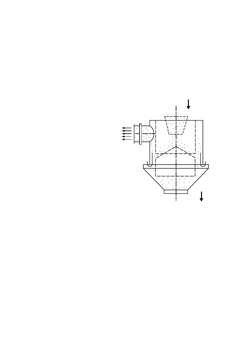
Automation is introduced at the stage of debaling. In order to obtain a product suitable for the
recycling process, operations to remove undesired impurities must be carried out. The machines required
are manifold and the necessity to employ them is related to the quality of the collected material. A few
essential machines are: (1) rotary screen, by which parts of the desired dimension are sorted out,
separating them from smaller and larger ones; (2) light-parts separation equipment, in which lighter
parts such as films are separated by air blowing from the plastic material to be recycled; (3) heavy-parts
separation equipment, in which heavy particles are separated and the operation is carried out by means
of air that shifts the material selectively; and (4) aluminum rejection equipment, which normally consists
of an electromagnetic drum placed in a suitable location on the train of operations. All such machines are
preliminary to the stage of selection into homogeneous plastics fractions.
6.11.3.1
Dry Separation
The cleaning of plastics is often combined with the
separation of other types of plastics and is
performed by either dry or wet process depending
on the quality of the collected material. A signi-
ficant advantage of dry cleaning with air, as
compared to wet cleaning, is that it has a lower
power consumption. Loose adhering dirt—and
this is the only type of sorting that can be
removed in a dry process—is loosened and pulver-
ized by the impact and rubbing caused during size
reduction. The dirt, then as dust, can be separated
by using an appropriate equipment. Examples of
this are screen units and air stream separator.
The screen unit is the most economical means
of removing the dirt. By selecting a screen with
suitably sized openings, it is possible to minimize
the amount of plastic discharged with the dust.
Electrostatic charge can however cause too many
dust particles to adhere to the plastic. The air
separator (Figure 6.18) is then the more suitable
device to use. Lighter-weight dust is carried out of
the unit by the opposed directional air stream.
Mixed plastics, including various types of
composite materials, that are to be dry-separated are first size-reduced (e.g., in a granulator)
before the different constituents are separated. The separation is done in a process based on differences
in material densities or shape and size of particles.
Screening may follow size reduction, depending on the material and the particle size distribution. In
the screen unit, all of the mixed material is divided into two or three size fractions, e.g., 0–2, 2–4, and 4–
6 mm. This is necessary since small heavy particles and large light pieces behave in the same manner, as
do heavy flakes and light conical pieces. The separation based on density difference is easier or only then
possible when all particles are of similar size.
Dry separation using air can be repeated several times, and the process is then classified as a cascade
separator. A cascade separator, also known as a zigzag separator, uses an air stream passing through a
rectangular zigzag channel from below (
). The material to be separated is fed to the top end of
the channel into the air stream. The separation point is set by adjusting the air-flow rate. Material
turbulence occurs in each section of the air stream channel, with lighter material being carried upward by
air stream to discharge and heavy material moving downward from step to step. Fine particles are
loosened from the larger ones and also from each other each time impact with side wall occurs. Cascade
separators produce more efficient separation than single-stage units due to dispersion taking place at
FIGURE 6.18
Schematic of air-stream separator.
Recycling of Polymers
6-35
q
2006 by Taylor & Francis Group, LLC
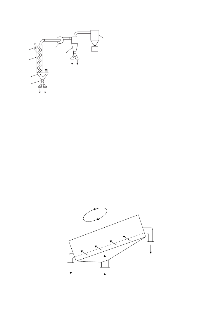
each kink in the channel. Typical applications for
the cascade separator are the separation of fibers
and insulation film or foam and soft film.
The principle of operation of a fluidized air bed
separator is shown in Figure 6.20. The material to
be separated is carried uphill by the orbital
vibration in the separation channel designed with
a rectangular cross-section. An adjustable air
stream is passed through the sieve surface in the
channel where it lifts the material. The particles
that are lifted higher in the air stream (that is,
jump higher due to elasticity) flow downhill and
are discharged from below. This type of fluidized
air bed separation process can also be enhanced by
using a multistage plant. A typical application for
this unit is the separation of rubber from rigid
thermoplastics or aluminum from plastics.
6.11.3.2
Wet Separation
Wet separation of plastics is a microseparation
method in which a suspension medium is used to
separate plastics with density higher or lower than the suspension medium. For example, water can be
used as medium to separate PE from PVC or PET. In this case, special tanks are used in which various
types of plastic flaks are mixed with water and then given a sufficient time to position themselves in the
most suitable way according to their density. Materials are subsequently extracted separately from the top
or bottom. This method is, however, not suitable for separating PVC from PET, because they have
similar density.
Researchers at Rutgers University [70] studied a method of PVC microseparation from PET, by which
PVC is subjected to a process of selective bulking that causes it to float. Such a method may be applied for
separating small quantities of PVC from large quantities of PET, as normally is the case in the U.S., but is
Direction of
motion
Air stream
Heavy
material
Light
material
FIGURE 6.20
Schematic of vibrating air separator.
Material
in
Heavy
material
Light
material
1
2
3
4
5
6
7
FIGURE 6.19
Schematic of air-stream (cascade)
separator. 1, Gate valve; 2, cascading (zigzag) channel;
3, container with air suction; 4, gate valve; 5, blower; 6,
cyclone; 7, filter with particle container.
6-36
Plastics Technology Handbook
q
2006 by Taylor & Francis Group, LLC

not suitable when PVC is a major component of the containers mix. Another wet method applicable to
PVC and PET containers, previously reduced to flakes, is flotation with surface active agents.
6.11.3.3
Other Methods
Need for using microseparation techniques arises in critical situations where minute concentrations of
identified contaminants adversely affect the post-consumer resin’s usefulness in high-value end-uses. In
many cases, microseparation, or the ability to sort resins by type, can be accomplished by air elutriation
techniques (e.g., dry separation techniques and described above), wet separation techniques (such as
sink/float tank technologies and hydrocyclones), magnets, electrostatic and electrodynamic method-
ologies, and optical scanners. Air aspiration and elutriation systems work well for separating light-
density foams and films from denser reground plastics, while density-based methods are better for
separating polyethylene from PET and denser resins.
Challenges to separate materials having similar densities, for example, PVC from PET regrind, or
polypropylene from polyethylene, remain. Examples of microsorting techniques commercialized so far
include electrostatic separation devices designed to sort by way of resin’s conductivity, supercritical fluids
which alter the separation fluid’s density, froth flotation using the alteration of a liquid’s surface tension
to separate various solids, and chemical dissolution based on the difference in solubility of various
plastics in selective solvents. Another development is a novel method to separate diverse resins by taking
advantage of their differences in stick temperature.
BASF’s Kali and Salz AG company, which has extensive experience in electrostatic separation of salts,
employs its own electrostatic separation process (ESTA) to the separation of plastics. Using density
separation, paper and plastic residues from labels and crowns are separated first. Then, following
pretreatment with surface active substances designed to enhance the electrostatic properties, the
homogeneously milled particles are charged electrically as they rub against each other. The extent of
electrostatic charge depends on the plastic. The particles then fall through a high-tension field and are
diverted at different angles depending on the charge, resulting in separation.
6.11.4
Resin Detectors: Type and Configuration
Detectors fall into four categories—x-ray, single-wavelength infrared (IR), full-spectrum IR, and color.
The earliest automated systems used x-rays, which are still the most effective means of determining the
presence of PVC. The chlorine atom in PVC emits a unique signal in the presence of x-rays by either x-ray
transmission (XRT) or x-ray fluorescence (XRF). The XRT signal passes through the container, ignoring
labels and other surface contaminants, and is capable of detecting a second container that may be stuck to
the first. XRF, on the other hand, bounces off the surface of the container and is useful for finding any
PVC, including labels and caps.
Systems for separating multiple types of plastics utilize a single wavelength of the near-infrared (NIR)
spectrum. These systems work on the basis of a simple determination of opacity and separate the stream
of mixed containers into clear (PET and PVC), translucent (HDPE and PP), and opaque (all pigmented
and colored materials) streams.
The most sophisticated detectors, however, employ full spectrum NIR. Since all plastics absorb IR to
different degrees and each resin has a unique “fingerprint,” these detectors can accurately separate each of
the resins. In later developments, filters for individual wavelengths are used for rapid identification and
there is promise for even faster, lower-cost systems.
The color detectors are, in fact, very small cameras capable of identifying a number of colors. When
combined with a resin-specific detector, they allows a variety of sorts based on both resin type
and color.
Containers must be separated and presented to a detector in order to collect data on each unit. That
information is then integrated via computer, and the container is tracked down the conveyor until it
reaches the appropriate ejection point, where it is removed by a timed blast of air. The two primary
Recycling of Polymers
6-37
q
2006 by Taylor & Francis Group, LLC
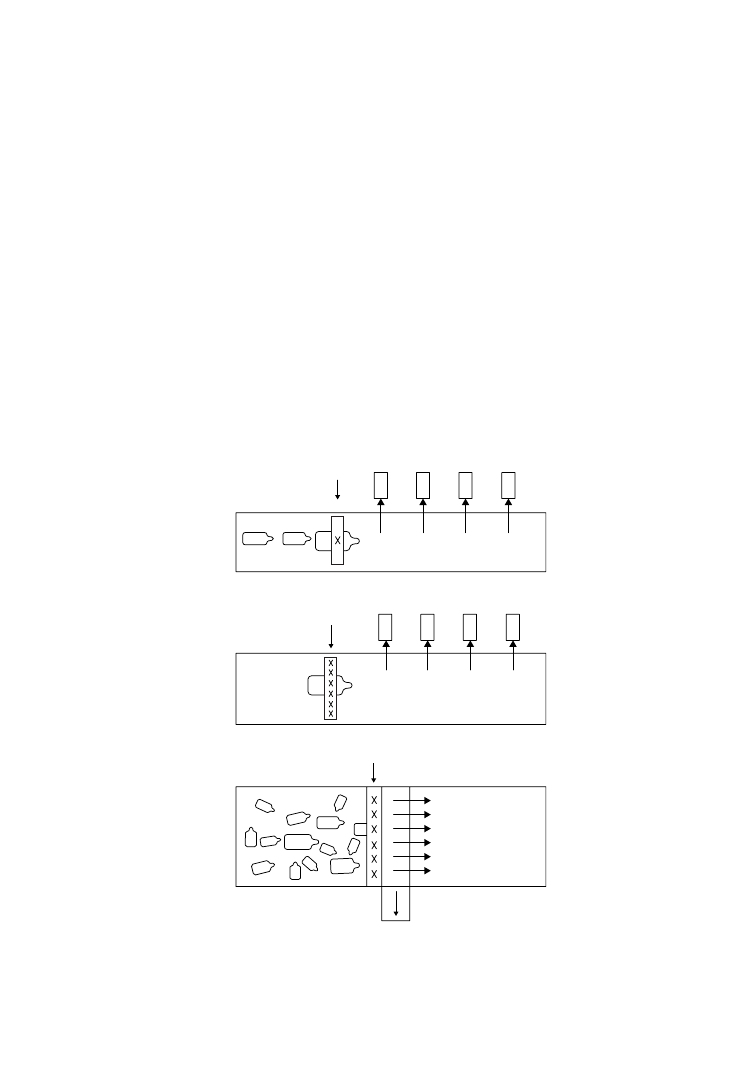
techniques for presenting containers to a detector are full-conveyor or single-file systems. Containers
delivered in a full-conveyor system can achieve higher throughput rates and are normally used to remove
a single material from the mixture. A singulated stream, on the other hand, has lower throughputs, but
allows sorting into a number of streams on a single pass.
Detectors are usually arranged in one of three configurations. The first is single detector/single
container (Figure 6.21a): this is the simplest setup for singulated containers. As each container passes the
detector, several readings are taken instantaneously and a decision is made by the computer. While
usually accurate, this process is subject to error if the container has a large label blocking the signal and
thus restricting data input to the computer. The second configuration is multiple detector/single
container (Figure 6.21b): as each container passes the detector assembly, it is read by a number of
detectors resulting in a more accurate reading. The third is multiple detector/multiple container
(Figure 6.21c): This is the standard configuration for a mass-flow system and has detectors spaced to
cover the width of the conveyor. When the target material is spotted, its position on the belt is noted and
accordingly an ejector removes it before falling off at the end of the belt.
Further development in autosort technology is represented by particulate-sorting units capable of
sorting by color. Applied in combination with the aforesaid resin detectors this facilitates autosorting
according to both resin-type and color.
Detector
(a)
(b)
(c)
Detector
Detector
Primary stream
Secondary
stream
Eject
1
Eject
2
Eject
3
Eject
4
Eject
1
Eject
2
Eject
3
Eject
4
FIGURE 6.21
Typical separation and sorting setups using three main detector systems: (a) single detector/single
sample; (b) multiple detector/single sample; and (c) multiple detector/multiple sample. (After Tomaszek, T. 1993.
Automated Separation and Sort, Modern Plastics, 34–36 (November).)
6-38
Plastics Technology Handbook
q
2006 by Taylor & Francis Group, LLC

6.11.5
Automatic Sortation
Most end-use markets of recycled plastics require that they be separated by resin type and color. For post-
consumer bottles, all lids, caps, and closures should also be removed because they are often of different
colors, and made of different resins than the bottle. The goal of any sorting process is to obtain the
highest purity, consistency, and quantity of a particular consumer resin type. This ensures the highest
end-use value for new products incorporating substantial amounts of the recycled resin.
In the widely used manual method of sorting, employees known as material handlers are stationed at
predetermined locations alongside the sort conveyor to remove the desired bottles for recycling. All caps
and closures still affixed to the bottles are manually removed by the handlers prior to or during sorting.
These manual methods of sorting, however, face many challenges, some of which are economic and
others environmental and aesthetic. Among the key hurdles are high cost of the labor-intensive process,
exposure of employees to the residual household and industrial chemicals contained in some of the
collected bottles, difficulty in sorting look-alike resins, and subjective material quality standards resulting
from manual sorting. Automating the container sorting process to overcome these hurdles has thus been
a major goal of the recycling industry.
An automatic separation process that includes various systems employing detectors currently available
in the market is ideally suited to macroseparation or macrosorting (separation of plastic fractions before
size reduction) when waste materials are still in the initial form (such as post-consumer bottles).
Macrosorting is one of the fastest-growing segments of the plastics recycling industry. Although
automated sorting, by resin type and color, can be accomplished after size reduction, most commercial
automated-sorting machines are designed to sort plastics containers in whole form before size reduction.
Some of the automated bottle-sorting systems are designed to sort certain bottles such as look-alikes,
while others are designed to separate all plastics bottles by resin type and color. The most commonly
encountered look-alike bottles are those fabricated from nonpigmented PVC and clear PET.
6.11.5.1
PVC/PET and Commingled Plastics Sortation
Both PVC and PET bottles are very recyclable. However, when the two types are received commingled,
the reprocessor can experience quality deficiencies due to rheological incompatibilities between these two
resins. This has been of special concern to the PET bottle reclaimer because, as the PET is heated to its
processing temperature, trace amounts of PVC can cause severe deterioration in the quality of the
reprocessed PET resin. Therefore the two resins must be separated prior to recycling.
Manual sorting of look-alike PVC and PET cannot meet the market’s needed quality. Therefore new
techniques have been engineered that will detect and separate bottles made from either of these two
resins. The first detector was developed by Tecoplast in Casumaro, Ferrara-Italy, to separate PVC from
PET. The application of this system resulted in the introduction of an automatic plant, processing drink
plastic bottles using the AZZURRA machine. The Tecoplast detector consists of an x-ray source and a
receiver that measures the bottle absorption while passing between the source and receiver. PVC has a
higher absorption compared to the other plastic due to the presence of a chlorine atom. The value of PVC
absorption, electronically processed through algorithms, makes it possible to detect its presence and
consequently to eject bottle.
Another detector is employed to line up bottles using a suction robot. The aligning process enables
bottles to be arranged in a suitable way for measuring transparency and color. Using this technology,
Tecoplast developed the first optical detector capable of establishing the quality of PET, thus allowing the
separation between clear PET and colored PET, besides the aforesaid separation from PVC. In a later
development, Govoni’s technology employed detectors performing these separations without alignment.
Other detectors have been developed in the U.S. A leading manufacturer of plastics sortation
equipment, ASOMA Instrument Inc. (Austin, TX), developed a simple operator-friendly device for
sensing the presence of chlorine atoms contained within the PVC resin. This sensor identifies PVC by
x-ray fluorescence as bottles fall through a chute or move on a belt conveyor, at the end of which either
the PVC or PET bottles are extracted—in most cases, by a burst of compressed air-jet actuated by the
Recycling of Polymers
6-39
q
2006 by Taylor & Francis Group, LLC

device, although mechanical devices have also been employed. The x-ray fluorescence sensitivity is so
reliable that a 10 ms analysis is all that is needed to make proper selection. Single-unit systems have been
developed that both detect and separate commingled bottles at production rates of 800–1200 lb/h, which
corresponds to between two and three bottles per second. As is the case with most macroseparation
devices, singulation (that is, alignment of bottles in a single file) is critical for this system to function at
high production rates while maintaining rigorous quality standards. With x-ray detection, sorted PET
streams having less than 50 ppm of PVC have been consistently produced, while, in contrast, manual
separation generally results in PET with 2000 ppm PVC [71].
Another example is a system made by National Recovery Technologies (NRT) Inc. (Nashville, TN)
[72]. This apparatus incorporates a proprietary electromagnetic screening process that also detects the
presence of chlorine as found in PVC bottles. Once detected, PVC bottles are pneumatically jettisoned
from the commingled bottle feed stream by a microprocessor-based air-blast system. The NRT
technology permits bottles to be delivered to the unit in a mass sort concept in either crushed or
whole form. This system does not require any special positioning or orientation of the bottles in order to
achieve high efficiency rates.
An optical detector developed by Magnetic Separation Systems (MSS) Inc. (Nashville, TN)
incorporates an optical sensing device with a transmission output range of 200–1500 nm to detect
both the resin composition and the shape of the inspected container. Additionally, a video camera is
employed to identify colored containers via computerized spectrographic matching. This information is
also processed through a high-speed microprocessor that has the ability to perform algorithmic analyses
and alarm the programmable logic controller (PLC) to actuate an ejection apparatus to sort the desired
bottle. Finally, an x-ray fluorescence sensor is used to sort PVC bottles from the PET bottle fraction. The
MSS detector system is thus designed to obtain separation of commingled plastics into homogeneous
material fractions, including PVC, clear PET, colored PET, multicolored HDPE, and translucent HDPE.
A modular sorting system of MSS, BottleSort, Incorporates a sensory apparatus designed to detect and
mechanically separate commingled plastic bottles in a process that includes several functions: debaling,
screening, sensing, separation, and electronic control. Sensing is performed both optically and with x-ray
fluorescence. Each BottleSort modular unit can process 1250 lb/h. Systems have been commercially
installed incorporating four units having a combined capacity to sort 5000 lb of commingled bottles
each hour.
A near-infrared spectrophotometry detector, developed by Automation Industrial Control (AIC) of
Baltimore, MD, allows identification of resin type, such as PET, HDPE, PVC, PP, LDPE, and PS. The
equipment is connected with another detector for color determination and the resulting data are
processed by computer with highly sophisticated software. The equipment thus enables separation of a
container mix into various components with a high degree of selectivity in regard to typology and color.
This type of detector, however, requires material singularization and lining up.
The PolySort automatic plastic bottle sorting system introduced by AIC is designed to receive
commingled plastic bottles in either baled or crushed form. At the heart of this sorting system is a
sophisticated video camera and color monitor incorporating a strobe to detect and distinguish colors in
the inspected plastic bottle. This optical scanning device interfaces with a computer to match the color of
the bottle against a master. The detector is reputed to detect and match up to 16 million shades of colors.
In addition, the system can be programmed to disregard labels on the bottles. Following color detection,
a near-infrared detection system scans the single-bottle stream at a rate of approximately 3000 times a
minute, to determine in less than 19 ms the primary resin found in each one. This is achieved by
matching the interferogram produced by the bottle to a known master for each base resin as stored in
the system.
Computations are coordinated through the use of a rotary pulse generator and sensing light curtain to
impel the qualified bottle to a discharge chute located on the sort conveyor. Although the standard
PolySort system is designed to detect and sort about 1500 lb of compacted bottles each hour, higher
production rates can be obtained by feeding multiple lines from one debaler.
6-40
Plastics Technology Handbook
q
2006 by Taylor & Francis Group, LLC

A point of consideration is the efficiency of separation that could nullify the high efficiency of a
detection equipment. Detection must be unfailingly followed by rejection of the detected bottle, and in
reality this does not always occur. Delivery systems in use today are effective but not 100% accurate. Most
errors that occur with an autosort process are due to mechanical delivery errors rather than error related
to detection. Therefore, a check on the operations of selection of the detected product is of primary
importance. Detectors with 99% or greater efficiency, if installed in series and in number of at least two
units, can bring the level of impurities within the limits required. For example, with a mix in the
proportion of 90% PET and 10% PVC, two detectors with 99.5% efficiency placed in series enable one to
obtain a level of impurities of 2.5 ppm, whereas with efficiency of 99% the value of residue is 10 ppm.
6.11.6
Recycle Installations
Special importance is generally attached to the techniques of electronic selection of homogeneous
fractions, as discussed above, while disregarding the phase of regeneration of selected plastics. This would
be justified if plastics articles were manufactured following criteria of perfect recyclability. However, such
criteria are not yet universally adopted or followed. Therefore, an accurate response must be given, in any
recycling plant design, to the problems posed by various elements that normally compose the item to be
recycled. Referring to liquid containers, in general, these consist of, in addition to the body made of
plastics, other foreign bodies that are to be removed. Such elements may be caps made of PE, PE with
PVC gaskets, aluminum, labels of PVC or tacky paper with different types of glue, and residues and dirt
that may have been added during the waste-collection phase.
Various operations, to be carried out in a specific sequence because of the problems posed by the type
of material, are grinding, dry separation, and wet separation. Machineries to be installed for these
operations are dictated by the typology and quality of recycle items.
Grinding is the first step following selection and requires attention and accuracy in design to ensure
optimum homogeneity of the ground product. Several types of grinding equipment in common use have
been described earlier.
The purpose of dry separation is the removal of a part in the dry phase. The process allows avoiding
problems of dissolution in water and relevant contamination. An air flotation method is used for dry
separation. Specially designed machines combining the effects of vibration and air flotation ensure
separation of flakes with different specific weight. Such machines are very useful for removal of parts of
labels that were freed by grounding. An extremely interesting application of this method is the separation
of PVC labels from PET bottle flakes.
Residues are normally washed out of material flakes using a class of equipment that includes
centrifugal cleaners, washing tanks, autoclaves, settling tanks, combined-action machines, scraping
machines (mechanical friction), and centrifugal machines (for water separation). The construction
details of the machinery and their installation according to a specific sequence are in the know-how of
various manufacturers and very little is revealed. In view of complex problems posed by post-consumer
plastics installations, it may, however, be said that it is not possible to expect miraculous results from key
processes carried out in a single passage and therefore the efficiency is maximized by repetition of the
same operation in more than one phase.
References
1.
La Mantia, F. P. 1992. Polym. Degrad. Stab., 37, 145.
2.
La Mantia, F. P., Perone, C., and Bellio, E. 1993. Blends of polyethylenes and plastics waste.
Processing and characterization, In Recycling of Plastic Materials, F. P. La Mantia, ed., pp. 131–36.
ChemTec Publishing, Toronto-Scarborough, Canada.
3.
Klason, C., Kuba´t, J., Mathiasson, A., Quist, M., and Skov, H. R. 1989. Cellul. Chem. Technol., 23,
131.
4.
Mathiasson, A., Klason, C., Kuba´t, J., and Skov, H. R. 1988. Resour. Conserv. Recycl., 2, 57.
Recycling of Polymers
6-41
q
2006 by Taylor & Francis Group, LLC

5.
Boldizar, A., Klason, C., Kuba´t, J., Na¨slund, P., and Saha, P. 1987. Inst. J. Polym. Mater., 11, 229.
6.
Henstock, M. E. 1988. Design for Recyclability. The Institute of Metals, London, England.
7.
Haylock, J. C., Addeo, A., and Hogan, A. J. 1990. Thermoplastic olefins for automotive soft interior
trim. SAE International Congress and Exposition, Detroit, MI (Feb. 26–March 2, 1990).
8.
Addeo, A. 1990. New materials for automotive interior. 22nd ISATA, Florence, Italy (14–18 May,
1990).
9.
Forcucci, F., Tomkins, D., and Romanini, D. 1990. Automotive interior design for recyclability.
22nd ISATA, Florence, Italy (14–18 May, 1990).
10.
Pfaff, R. 1990. Material recycling of polypropylene from automotive batteries—process and
equipment, In Second International Symposium, J. H. L. Van Linden, ed., pp. 37–36. The
Mineral, Metals and Materials Society, Warrendale, PA.
11.
Basta, N. 1990. Chem. Eng., 97, 37 (Nov. 1990).
12.
Boeltcher, F. P. 1991. ACS Polym. Prepr., 32, 2, 114.
13.
Curto, D., Valenzen, A., and La Mantia, F. P. 1990. J. Appl. Polym. Sci., 39, 865.
14.
La Mantia, F. P. and Curto, D. 1992. Polym. Degrad. Stab., 36, 131.
15.
Ide, F. and Hasegawa, A. 1974. J. Appl. Polym. Sci., 18, 963.
16.
Cimmino, S., Cuppola, F., D’orazio, L., Greco, R., Maglio, G., Malinconico, M., Mancarella, C. et al.
1986. Polymer, 27, 1874.
17.
Sinn, H., Kaminsky, W., and Janning, J. 1976. Angew. Chem., 88, 737; Sinn, H., Kaminsky, W., and
Janning, J. 1976. Angew. Chem. Int. Ed. Engl., 15, 660.
18.
Kaminsky, W. 1995. Adv. Polym. Technol., 14, 4, 337.
19.
Hirota, T. and Fagan, F. N. 1992. Die Makromol. Chem., Macromol. Symp., 57, 161.
20.
Paci, M. and La Mantia, F. P. 1998. Polym. Degrad. Stab., 61, 417.
21.
Scheirs, J. 1998. Polymer Recycling Science, Technology and Application. Wiley, New York.
22.
Villain, F., Coudane, J., and Vert, M. 1995. Polym. Degrad. Stab., 49, 393.
23.
Datye, K. V., Raje, H., and Sharma, N. 1984. Resour. Conserv., 11, 117.
24.
De Winter, W. 1992. Die Makromol. Chem., Macromol. Symp., 57, 253.
25.
Hellemans, L., De Saedeleer, R., and Verheijen, J. 1997. U.S. Patent 4,008,048 to Agfa Gaevert.
26.
Fisher, W. 1960. U.S. Patent 2,933,476 to Du Pont.
27.
Gintis, D. 1992. Die Makromol. Chem., Macromol. Symp., 57, 185.
28.
Richard, R. 1991. ACS Polym. Prepr., 32, 2, 144.
29.
Fujita, A. A., Sato, S. M., and Murakami, M. M. 1986. U.S. Patent 4,609,680 to Toray Industries Inc.
30.
Malik, A. I. and Most, E. 1978. U.S. Patent 4,078,143 to Du Pont.
31.
Vaidya, U. R. and Nadkarni, V. M. 1988. J. Appl. Polym. Sci., 35, 775; Vaidya, U. R. and Nadkarni, V. M.
1988. J. Appl. Polym. Sci., 38, 1179.
32.
Anon. 1991. Eur. Chem. New, 30 (Oct. 28, 1991).
33.
Dabholkar, D. A. and Jain, M. U.K. Patent Application 2041916; C.A., 94: 209688r.
34.
Thiele, U. 1989. Kunststoffe, 79, 11, 1192.
35.
Adshiri, T., Sato, O., Machida, K., Saito, N., and Arai, K. 1997. Kagaku Kogaku Ronbun., 23, 4, 505.
36.
Sako, T., Okajima, I., Sugeta, T., Otake, K., Yoda, S., Takebayashi, Y., and Kamizawa, C. 2000.
Polym. J., 32, 178.
37.
Genta, M., Tomoko, I., Sasaki, M., Goto, M., and Hirose, T. 2005. Ind. Eng. Chem., 44, 3894.
38.
Tokiwa, Y. and Suzuki, T. 1977. Nature, 270, 76.
39.
Witt, V., Mu¨ller, R.-J., and Deckwer, W.-D. 1995. J. Environ. Polym. Degrad., 3, 215.
40.
Mu¨ller, R. J., Schrader, H., Profe, J., Dresler, K., and Deckwer, W.-D. 2005. Macromol. Rapid
Commun., 26, 1400.
41.
Kaminsky, W. 1985. Chem. Eng. Technol., 57, 9, 778.
42.
Hagenbucher, A. 1990. Kunststoffe, 80, 4, 535.
43.
Niemann, K. and Braun, U. 1992. Plastverarbeiter, 43, 1, 92.
44.
Boeltcher, F. P. 1991. ACM Polym. Prepr., 32, 2, 114.
45.
Meister, B. and Schaper, H. 1990. Kunststoffe, 80, 11, 1260.
6-42
Plastics Technology Handbook
q
2006 by Taylor & Francis Group, LLC

46.
Mu¨ller, P. and Reiss, R. 1992. Die Makromol. Chem., Macromol. Symp., 57, 175.
47.
Grigat, E. 1978. Kunststoffe, 68, 5, 281.
48.
Lentz, H. and Mormann, W. 1992. Die. Makromol. Chem. Macromol. Symp., 57, 305.
49.
La Mantia, F. P. ed. 1996. Recycling of PVC and Mixed Plastic Waste, pp. 265–36. ChemTec
Publishing, Toronto-Scarborough, Canada.
50.
Braun, D. 1992. Die Makromol. Chem., Macromol. Symp., 57, 265.
51.
Braun, D., Michel, A., and Sonderhof, D. 1981. Eur. Polym. J., 17, 49.
52.
Bonau, H. 1992. Die Makromol. Chem., Macromol. Symp., 57, 243.
53.
Dang, W., Kubouchi, M., Yamamoto, S., Sembokuya, H., and Tsuda, K. 2002. Polymer, 43, 2953.
54.
Dang, W., Kubouchi, M., Sembokuya, H., and Tsuda, K. 2005. Polymer, 46, 1905.
55.
Sembokuya, H., Yamamoto, S., Dang, W., Kubouchi, M., and Tsuda, K. 2002. Network Polym., 23,
10.
56.
Kriger, S. G. 1994. Recycling equipment and systems. Mod. Plast., November E-47 .
57.
Vezzoli, A., Beretta, C. A., and Lamperti, M. 1993. Processing of mixed plastic waste, In Recycling of
Plastic Materials, F. P. La Mantia, ed., pp. 219–36. ChemTec Publishing, Toronto-Scarborough,
Canada.
58.
Shenian, P. 1992. Die Makromol. Chem., Macromol. Symp., 57, 219.
59.
Dinger, P. W. 1994. Bottle reclaim systems. Mod. Plast., A-46 (November 1994) .
60.
Hirota, T. and Fagan, F. N. 1992. Die Makromol. Chem., Macromol. Symp., 57, 161.
61.
Beckman, J. A., Crane, G., Kay, E. L., and Laman, J. R. 1974. Rubber Chem. Technol., 47, 597.
62.
Sperber, R. J. and Rosen, S. L. 1974. Polym. Plast. Technol. Eng., 3, 2, 215.
63.
Paul, J. 1986. In Encylopedia of Polymer Science and Engineering, Vol. 14, H. Mark, ed., p. 787.
Wiley, New York..
64.
Corley, B. and Radusch, H. J. 1998. J. Macromol. Sci. Phys. B, 37, 265.
65.
Wu, S. 1985. Polymer, 26, 1855.
66.
Swor, R. A., Jenson, L. W., and Budzol, M. 1980. Rubber Chem. Technol., 53, 1215.
67.
Tuchman, D. and Rosen, S. L. 1978. J. Elastom. Plast., 10, 115.
68.
Oliphant, K., Rajalingam, P., and Baker, W. E. 1993. Ground rubber tire-polymer composites, In
Recycling of Plastic Materials, F. P. La Mantia, ed., ChemTec Publishing, Toronto-Scarborough,
Canada.
69.
Grigoryeva, O. P., Fainleib, A. M., Tolstov, A. L., Starostenko, O. M., and Lievana, E. 2005. J. Appl.
Polym. Sci., 95, 659.
70.
Frankel, H. 1992. Proceedings of Recycle 92, Davos, Switzerland (April 7–10, 1992).
71.
Tomaszek, T. 1993. Automated separation and sort. Mod. Plast., 34–36 (November 1993).
72.
Gorttesman, R. T. 1992. Proceedings of Recycle 92, Davos, Switzerland (April 7–10, 1992).
Recycling of Polymers
6-43
q
2006 by Taylor & Francis Group, LLC

Document Outline
- Table of Contents
- Chapter 6: Recycling of Polymers
- 6.1 Introduction
- 6.2 Outline of Recycling Methods
- 6.3 Recycling of Poly (Ethylene Terephthalate)
- 6.4 Recycling of Polyurethanes
- 6.5 Recycling of Poly (Vinyl Chloride)
- 6.6 Recycling of Cured Epoxies
- 6.7 Recycling of Mixed Plastics Waste
- 6.8 Post-Consumer Polyethylene Films
- 6.9 Recycling of Ground Rubber Tires
- 6.10 Recycling of Car Batteries
- 6.11 Plastic Recycling Equipment and Machinery
- References
- Chapter 6: Recycling of Polymers
Wyszukiwarka
Podobne podstrony:
ef6684 c006
DK3171 C006
7039
7039
praca-magisterska-7039, 1a, prace magisterskie Politechnika Krakowska im. Tadeusza Kościuszki
7039
7039
7039
7039
7039
ef6684 c006
DK3171 C006
7039 A008
7039 A009
7039 A002
więcej podobnych podstron