HARDI CIRCULATION SYSTEM
679023-2002/01
Number
Number
Number
Number
Numbers and their meaning
s and their meaning
s and their meaning
s and their meaning
s and their meaning
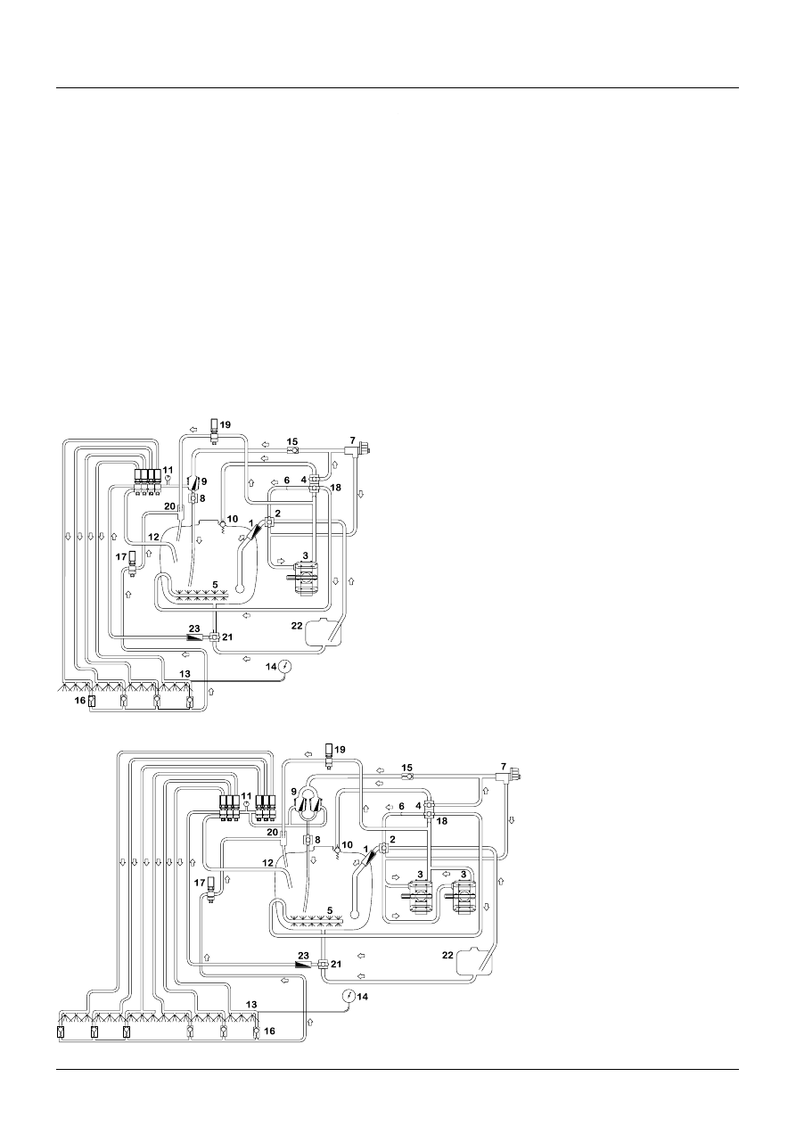
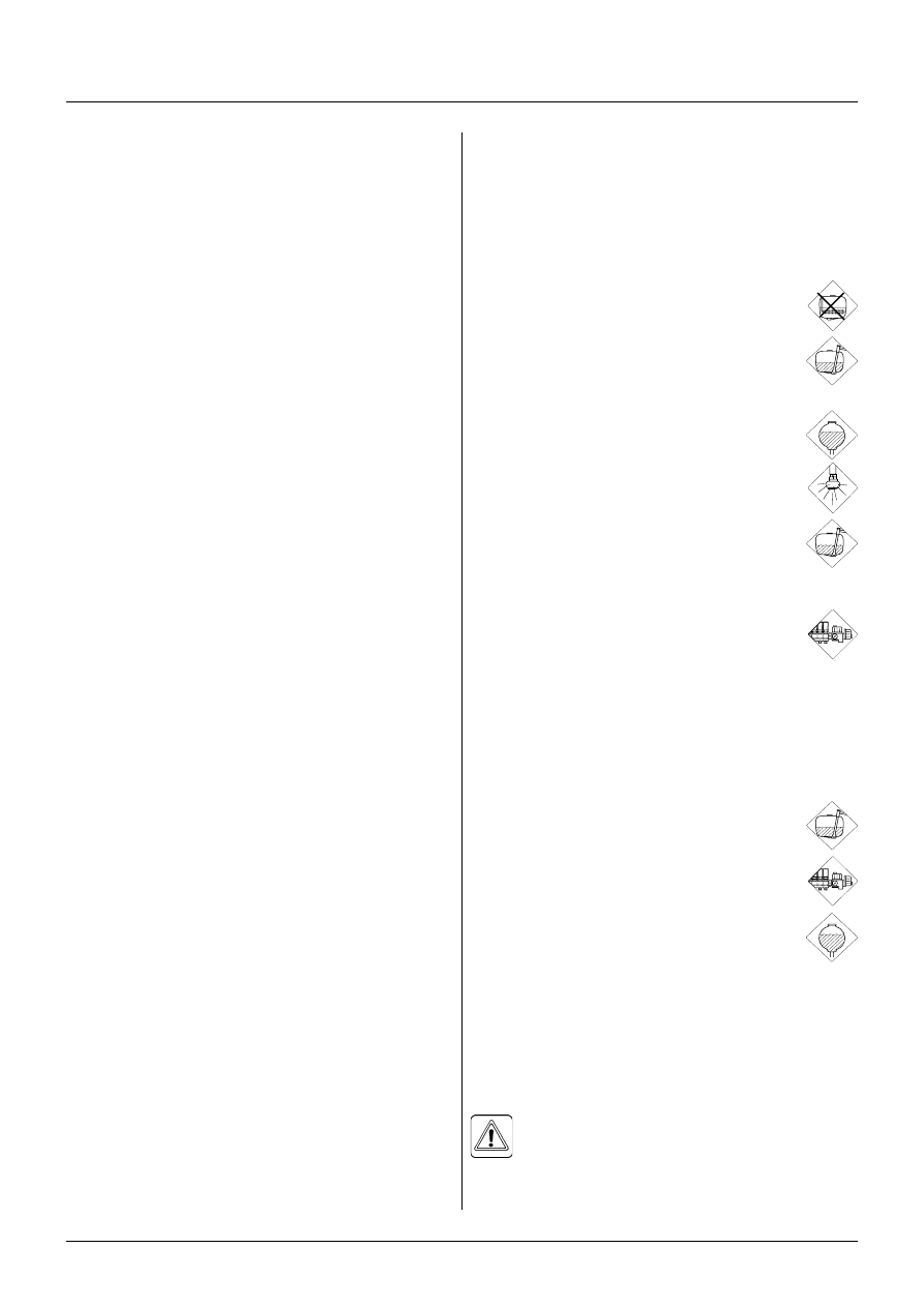
1. Suction filter
2. Suction manifold (black)
3. Pump / Double pump (HCFS)
4. Pressure manifold (green)
5. Agitation
6. Without agitation
(pressure equalisation)
7. HARDI MATIC
8. Return line (Self-cleaning filter)
9. Self-Cleaning Filter
10.Safety valve
11.Distribution valves
12.Return from
Pressure Equalisation
13.Sprayer boom
14.Pressure gauge
15.Non-return valve
16.Non-return valves
17.Circulation valve
18.Agitation valve
19.Ejector valve
20.Ejector
21.Circulation suction valve
22.Rinsing tank
23.Circulation filter
Description
Description
Description
Description
Description
HARDI CIRCULATION SYSTEM: By the incorporation of an ejector and connecting the boom lines with tank and
MANIFOLD, it enables the formation of a flow from tank (or rinse tank) through the boom lines when the sprayer is
not spraying. The HARDI CIRCULATION SYSTEM provides the following features compared to a conventional
sprayer: Instant spraying when starting since boom lines are primed prior to start, reduced risk of sedimentation in
boom lines since there is a continous flow, which creates a possibility to flush and clean the boom without spraying.
This do not apply to the nozzles, as there are no flow in them when spraying is off.
Function
Function
Function
Function
Function
The sprayer can be equipped with HARDI CIRCULATION SYSTEM in combination with either a conventional liquid
system or a High Capacity Fluid System (HCFS). The operation of the liquid system is identical for both systems.
At a sprayer with HARDI CIRCULATION SYSTEM, an extra valve connected with a circulation suction filter is added
to the MANIFOLD system. The valve and filter are fitted to the right side of the MANIFOLD valves. This valve has
three positions: circulation from main tank, circulation from rinse tank or circulation off (see signs on valve). When
spraying is on, the sprayer functions are like a normal sprayer, but when distribution valves are turned off, valve
no. 17 and 19 open (see function diagram) and allow a flow to the ejector (20) and from the distribution valves (11).
Fluid through valve 19 comes from pump and is led into the ejector. This causes a vacuum in hoses through valve
17 allowing the fluid to be sucked from boom pipes through valve 17 and the ejector back into main tank.
Function dia
Function dia
Function dia
Function dia
Function diagggggrrrrram - High Ca
am - High Ca
am - High Ca
am - High Ca
am - High Capacity F
pacity F
pacity F
pacity F
pacity Fluid Sy
luid Sy
luid Sy
luid Sy
luid System (HCFS)
stem (HCFS)
stem (HCFS)
stem (HCFS)
stem (HCFS)
Function dia
Function dia
Function dia
Function dia
Function diagggggrrrrram - con
am - con
am - con
am - con
am - convvvvventional liquid sy
entional liquid sy
entional liquid sy
entional liquid sy
entional liquid system
stem
stem
stem
stem
Detailed description on use of MANIFOLD system can
be found in the instruction book for the specific sprayer.
NOTE! The new EVC section valve with an extra return
flow channel is a pre-requisite for HARDI CIRCULATION
SYSTEM.
Diagrams for standard EVC system and for High Capa-
city Fluid System (HCFS) with HARDI CIRCULATION
SYSTEM are shown to the left and below.
HARDI CIRCULATION SYSTEM
679023-2002/01
Cleaning the spr
Cleaning the spr
Cleaning the spr
Cleaning the spr
Cleaning the spraaaaayyyyyer
er
er
er
er
1. Dilute remaining spray liquid in the tank with water
corresponding to approximately
1
/
4
of volume in Rinsing
tank and spray the liquid out in the field that you have
just sprayed - See paragraph Use of rinsing tank and
rinsing nozzles point A, except paragraph 5, 7 and 11.
NOTE! It is advisable to increase the forward speed
(double if possible) and reduce the pressure to 1.5 bar
(20 psi).
2. Select and use the appropriate protective clothing.
Select detergent suitable for cleaning and suitable
deactivating agents if necessary.
3. Rinse and clean sprayer and tractor externally. Use
detergent if necessary.
4. Remove tank suction filters and clean. Be careful not to
damage the mesh. Replace suction filter top. Replace
filters when the sprayer is completely clean.
5. With the pump running, rinse the inside of the tank.
Remember the tank roof. Rinse and operate all compo-
nents and any equipment that has been in contact with
the chemical.
Before opening the distribution valves and spraying the
liquid out, decide whether this should be done in the
field again or on an appropriate grass covered area
near the farm.
6. After spraying the liquid out, stop the pump and fill at
least
1
/
5
of the tank with clean water. Note that some
chemicals require the tank to be completely filled. Add
appropriate detergent and/or deactivating agent, e.g.
washing soda or Triple ammonia.
NOTE! If a cleaning procedure is given on the chemical
label, follow it closely.
7. Start the pump and operate all controls enabling the
liquid to come in contact with all the components.
Leave the distribution valves until last. Some deter-
gents and deactivating agents work best if left in the
tank for a short period. Check the label. The Self-
Cleaning Filter can be flushed by removing the by-pass
hose from the bottom of the filter. Stop the pump and
remove the hose. Start the pump for a few seconds to
flush filter. Be careful not to lose the restrictor nozzle.
8. Drain the tank and let the pump run dry. Rinse inside of
the tank with a large amount of clean water
(~200 l), again letting the pump run dry.
9. Stop the pump. If the pesticides used have a tendency
to block nozzles and filters, remove and clean them
immediately. Also check for sediment on the pressure
side of the safety valve for the Self-Cleaning Filter.
Use of rinsing tank and rinsing nozzles
Use of rinsing tank and rinsing nozzles
Use of rinsing tank and rinsing nozzles
Use of rinsing tank and rinsing nozzles
Use of rinsing tank and rinsing nozzles
The incorporated rinsing tank can be used for two
different purposes.
A. In-field diluting of remaining spray liquid residue in the
spraying circuit for spraying the liquid in the field
before cleaning the sprayer.
1. Empty the sprayer as much as possible. Turn
the green pressure valve towards No Agita-
tion and spray till air comes out of all noz-
zles.
2. Remove the tank filter basket.
3. Set circulation system for suction from main
tank.
4. Engage and set the pump at approximately 300 r.p.m.
5. Turn black suction valve towards Rinsing tank.
6. Turn green pressure valves towards Rinsing
nozzle (if fitted). Or else choose return to
main tank.
7. When rinsing water corresponding to ap-
proximately
1
/
4
of volume in Rinsing tank is
used, turn black suction valve towards
Suction from main tank.
8. Operate all valves, so that all hoses and
components are rinsed.
9. Let the circulation system run for about 2 minutes.
10.Turn green pressure valve back to Operating
unit and spray liquid in the field you have just
sprayed. Use low pressure (1.5 bar) and high
speed.
11.Repeat point 5-10 until the rinsing tank is empty.
NOTE! If a cleaning procedure is given on the chemical
label, follow it closely.
B. Rinsing of the pump, operating unit, spray lines, etc.
in case of stop in spraying before main tank is empty
(e.g. in case of rain etc.).
1. Engage pump and set circulation system for
suction from main tank.
2. Open valve to Operating unit at pressure
side of the Manifold system.
3. Close Self-cleaning filter (yellow valve).
4. Turn blue suction valve for circulation system
towards Rinsing tank.
5. When at least
1
/
8
volume of clean water tank
has been emtied out, then close circulation
system at the blue suction valve.
6. Start spraying. Spray water from rinsing tank in the
field until all nozzle tubes/nozzles have been flushed
with clean water.
7. After 2 minutes or when Rinsing tank is empty, then
disengage pump.
8. Open Self-cleaning filter again.
WARNING! The rinsing nozzles cannot always
guarantee a 100% cleaning of the tank. Always
clean manually with a brush afterwards, espe-
cially if crops sensitive to the chemical just sprayed are
going to be sprayed afterwards!
Oper
Oper
Oper
Oper
Operaaaaating
ting
ting
ting
ting
A sprayer with HARDI CIRCULATION SYSTEM is
operated like other HARDI sprayers.
HARDI CIRCULATION SYSTEM has an extra valve in
the Manifold system. This valve is used to choose
between circulation from main tank or from rinsing tank.
In a spraying situation the valve is set for suction from
the main tank. The valve is set for suction from Rinsing
tank in a cleaning situation. For further cleaning details,
see paragraph Use of rinsing tank and rinsing nozzles.
Wyszukiwarka
Podobne podstrony:
CIrculation systems over China
Quick Study Chart Circulatory System (BarCharts Inc, 2004) WW
50 Gb in2 Magnetic Disk Drive System Design Project
System finansowy w Polsce 2
Systemy operacyjne
Systemy Baz Danych (cz 1 2)
Współczesne systemy polityczne X
System Warset na GPW w Warszawie
003 zmienne systemowe
elektryczna implementacja systemu binarnego
09 Architektura systemow rozproszonychid 8084 ppt
SYSTEMY EMERYTALNE
3 SYSTEMY LOGISTYCZNE
modelowanie systemow
16 Metody fotodetekcji Detektory światła systematyka
więcej podobnych podstron