SURREALISTE action - Wiwi - Stirling gamma
http://www.surrealiste.org/modules/wiwimod/index.php?page=Stirling+gamma
1 sur 12
7/12/2006 17:59
Fabriquer un moteur Stirling gamma
Cette technique est 100% fonctionnelle
Fiche ouverte
fiche version 1.0
*****************************************************
Technique en cours de développement sur SURREALISTE action
*****************************************************
DEBUT DE LA FICHE
Présentation
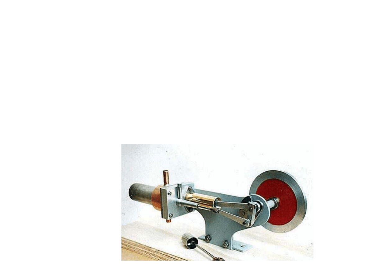
Voici les plans pour réaliser un moteur stirling de type gamma – le même que le moteur de démo de
Surréaliste. Les plans sont au format Intellicad (fichiers .dwg), à vous d’adapter les mesures à la taille du
moteur que vous voulez fabriquer. Ils peuvent servir aussi bien pour une maquette que pour fabriquer un
modèle de puissance capable d’entraîner une génératrice. En l’état il s’agit de plans de base, des
améliorations sont possibles (par exemple rajouter un gaz de travail ou améliorer l’étanchéité). Le type de
moteur permet beaucoup de possibilités, le seul problème qui se pose c’est qu’il faut du matériel et des
compétences pour l’usiner.
SURREALISTE action - Wiwi - Stirling gamma
http://www.surrealiste.org/modules/wiwimod/index.php?page=Stirling+gamma
2 sur 12
7/12/2006 17:59
Télécharger les plans
Télécharger les plans au format Intellicad (.dwg)
en cliquant ce lien
Télécharger les plans au format image (.jpg)
en cliquant ce lien
Explications
*********************
Pour l’instant, les explications sont encore en anglais, le temps que quelqu’un veuille bien se dévouer pour
les traduire.
*********************

SURREALISTE action - Wiwi - Stirling gamma
http://www.surrealiste.org/modules/wiwimod/index.php?page=Stirling+gamma
3 sur 12
7/12/2006 17:59
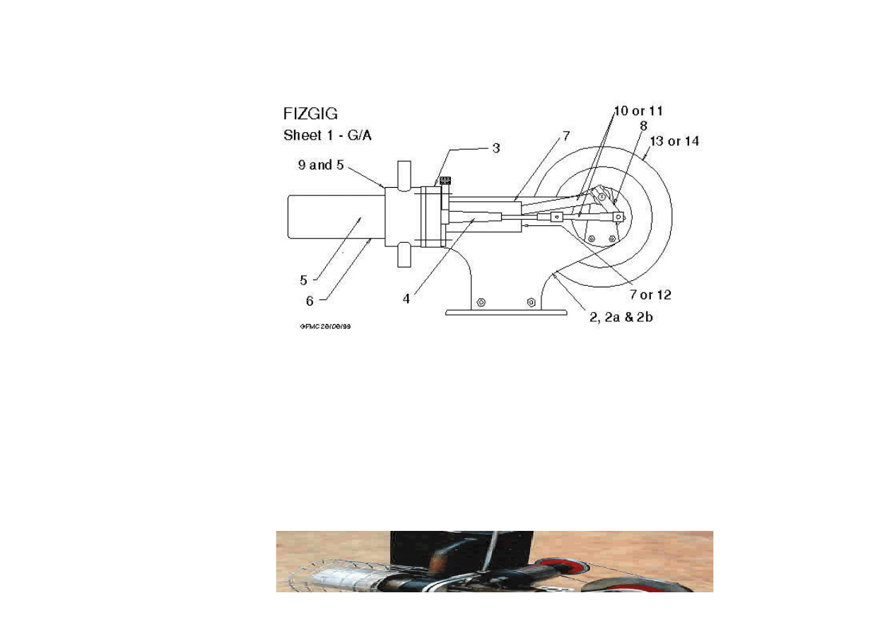
The Bed Sheets 2 2a 2b
Cut the bed from either 2mm or 3mm (1/10" or 1/8") mild steel sheet and if you are unable to find a
suitable piece of metal locally remember that the firms who supply frame steel to model loco builders will
be able to help with 3mm material. If you intend to make the con-rod with the split big-end it is essential
that the piston stroke is truly perpendicular to the crankshaft and to ensure this the bed plate must be
flat. Check it before marking out by first removing any burrs from the edges and holding it up to the light
with a steel rule laid across the surface. On the concave surface you will see a glimpse of light between the
ruler and the metal, and this is the side which you should mark out on. Drill holes first, the relationship
between the bearing tube hole and the block fixing screw holes being particularly important. Then cut the
outer shape. This is for appearance only and not critical, whether you chain drill the curves and file them
or attack them with an angle grinder is up to you. The next job is to get that concave surface flat and after
removing any burrs round the edge, a few strokes with a new file laid flat on the surface should suffice.
Crankshaft Bearing Tube Sheet 2a
It is important that the flange is exactly square with the hole through the centre of the tube and this will
present no difficulties to the experienced turner with half decent equipment. However, beginners often
have difficulty drilling long holes accurately and the combination of an inaccurately sharpened drill with an
imperfectly aligned tailstock can make it very difficult. So unless you are really confident, chuck the rod
and drill the hole first, starting truly in the centre at the flange end. Then remove it from the chuck and
make a mandrel to mount it on. Chuck a length of 3/8" dia mild steel with about 3/4" protruding and turn
this down to a few thous (thousandths of an inch) over 9/32" dia and then use a fine file to put a very
slight taper on it, so that the tube, flange end first, will just force on for about 1/2". Squirt plenty of oil
into the tube before supporting the outer end of the tube with the tailstock centre, Then turn the outside

SURREALISTE action - Wiwi - Stirling gamma
http://www.surrealiste.org/modules/wiwimod/index.php?page=Stirling+gamma
4 sur 12
7/12/2006 17:59
into the tube before supporting the outer end of the tube with the tailstock centre, Then turn the outside
of the tube down to 3/8" dia, leaving the flange just over 1/16" thick. Finish this side of the flange with a
single cut to leave it true. Now remove from the chuck and knock out the mandrel. Chuck the tube gently
by the 3/8" dia and take very light cuts to reduce flange thickness to a bare 1/16".
Soldering Sheet 2a
Support the plate horizontally with the tube hanging thro' the hole and three short pieces of silver solder
wire under the flange. Flux thoroughly and heat mostly from above playing the flame round the flange so
that it heats at the same rate as the plate. When you see the solder melt, move the flame to the
underside to `draw' the solder towards the heat. With reasonable luck a fine fillet of solder behind the
plate will confirm penetration. In the case of the thinner, 2mm or 1/10", metal we now need to make up
the web and collar as shown on Sheet 2b. These should be silver soldered together and the faces that will
fit against the plate filed flat before soft soldering on to it. After soldering you can use soldering iron to
leave a fillet of solder along the web which, after painting, will give a look-a-like casting effect.
Crankshaft Bushes Sheet 2a
The bushes are turned to an easy sliding fit in the tube and either drilled 3/16" or drilled undersized and
reamed 3/16". Part off the two bushes to length and glue into the tube as follows. Insert the, lightly oiled,
length of silver steel rod that will become the crankshaft through the tube to project from each end. Slide
one of the bushes on to it and enter this into one end of the tube. Slip the other bush on to the other end
of the rod and enter it into the other end of the tube. With about 1/32" of each bush in the tube, apply a
tiny drop of Loctite 603* to the first bush, close to the tube face and turn the bush, to distribute the glue,
as you push it home into the tube. Leave a bare 1/32" projecting, just enough to accommodate any fillet
of glue that oozes out and prevent it falling on to the shaft . Repeat with the other bush and leave for a
few minutes before checking that the rod is free. If it isn't, grip it in the vice to pull it out and use a pipe
cleaner to clean the bushes before re-entering it. If the vice won't shift it, use a blowlamp to destroy the
bond, remove the bushes, clean up and start again with an even smaller drop of glue ----.
*Loctite 601 was used on both prototypes but now appears to have been superseded by 603.
Cylinder Mounting Block. Sheet 3
Cut from 3/8" Aluminium bar and hold in the 4-jaw chuck to machine the sawn edges square, or, if bar
isn't available, cast an oversized block in a simple folded tin-plate mould about 5/8" deep and machine all
over in the 4-jaw. Begin by holding it by the edges and machining the first, concave, surface flat. Now
chuck it with this face firmly against one of the jaws and, with a small packing piece between the centre of
the opposite jaw and the other face, machine the first edge flat. Re-chuck it with this edge against a jaw
and packing against the opposite jaw to machine the adjacent edge and repeat for the third edge. The
block can now be held between opposite edges to machine the last one after which it can be chucked by
the edges to machine the other face Finally check the dimensions and machine it down to the correct size,
and to ensure that the two faces are truly parallel, a parallel packing should be inserted between the block
and the chuck face for the final facing. A ring from an old ball race is ideal for this. Mark out, and drill the
holes for the cylinder and chamber fixing screws, the displacer bush tube and the two screws to hold the
block to the bed. Tap these two and the one for the tube. The only awkward job here is the skew hole.
Hold the block at the correct angle in your drilling machine vice and begin drilling with a small, say 3/16",
end-mill. When this has entered to its full diameter, replace by the same sized drill and continue thro'.
Alternatively, drill from both sides, using a hand brace and carefully skewing the drill. Either way, you will
need to finish by filing the port to the shape shown. Cut the register disc approx' 1/16" oversize from
1/32" sheet aluminium and flatten it by a good squeeze in the vice. Chuck a piece of scrap material, about

SURREALISTE action - Wiwi - Stirling gamma
http://www.surrealiste.org/modules/wiwimod/index.php?page=Stirling+gamma
5 sur 12
7/12/2006 17:59
1/32" sheet aluminium and flatten it by a good squeeze in the vice. Chuck a piece of scrap material, about
1" diameter, drill a short 1/4" hole in the centre and then face it to make a 'chucking piece'. Glue the disc
to its face with Loctite 603 and hold it firmly in place (with the tailstock barrel?) until the glue is set and
then turn to size and drill or drill and bore the centre hole. (There is less risk of breaking the glued joint if
you drill a small hole and open it up to 0.2" with a tiny boring tool.) Ensure that no burr remains round the
hole. Remove from the chuck, heat gently to remove the disc and drill a 3/16" hole to line up with the port
but don't fix the disc to the block until the displacer bush tube is completed.
Very sharp eyed folk may have noticed the laminar appearance of the block in the photo. This was an
experiment with the second engine to obviate the need for casting the block and it is built up from three
pieces of 1/8" aluminium sheet glued together with Loctite 601. The surfaces to be glued were first
roughened with coarse abrasive paper, the Loctite applied and the assembled pieces were then clamped
together in a vice for 24 hours before machining the edges as described above. The tricky part was drilling
the holes and, after the first attempt had broken one of the joints, it was glued back together and mole
grips were used to hold it together during the drilling of the four corner holes. The port was drilled, and
the two holes in the edge and the centre hole were all drilled and tapped, by hand, while it was clamped in
the vice. Care is needed to keep the centre hole square with the surface, but the built up block certainly
works and could be an alternative to a bar or a casting.
Displacer etc Sheets 4 and 5
Drill and turn the displacer rod bush tube from 7/16" diameter steel rod. Again we have the problem of
drilling a long hole and in this case it can be dealt with by first turning the end down, cutting the thread
and turning the nose to fit the register disc before drilling. If the drill wanders make up a carrier from a
strip of metal with a tapped hole at one end to match that on the tube and turn the outside diameter taper
between centres, finishing by taking the tiniest amount off the full diameter at the thread end - just
enough to true it up with the hole. Now hold it, firmly, in the chuck by this 'full' diameter to lightly skim
the face behind the thread before screwing the block fully home on to it. Check that sufficient 'nose'
projects through to locate the register disc, skimming off any excess, Use Loctite 603 to glue the register
disc to the block and hold it firmly (between chuck jaws and tailstock barrel?) until cured.
Remove the assembly from the chuck and hold the block in the vice to file out the port to approx 1/4" dia,
keeping within the limits shown on Sheet 3 and working from the disc side to avoid disturbing it. Finally
file the 3/16" x 3/16" square flat on the top of the tube to accommodate the lubricator screw, drill its
centre and tap 7 BA. (The correct procedure here would be to mill the flat or counterbore the hole to give
an accurate seating for the screw. However the air pressure is extremely low and the trace of oil on the
thread gives an adequate seal.) The screw thread must be short enough to prevent it touching the rod.
Two displacers are possible. The original engine used an aluminium 'Steradent' (denture cleaning tablets)
tube and a heater/air chamber made from a length of bicycle frame tube. This was very satisfactory but
after recommending it to friends I was told that the aluminium tubes were no longer available, having
been superseded by plastic. So for the second engine I bought a matching pair, heater and displacer, of
stainless steel tubes from Sterling Stirling . Of near identical sizes, these could be substituted without any
difficulty. However they are really intended for much more powerful pressurized engines running at higher
temperatures and whilst this is no disadvantage with the heater cap, the displacer is really too heavy for
Fizgig although it does have the slight advantage that it is fireproof and already the correct length.
However, I then discovered that the aluminium tubes are still available, used to pack a more powerful
grade of Steradent for coping with nicotine stains etc, and one of these was used for the second engine.
The safest way to cut the tablet tube is to chuck a length of broomstick and turn it down until the tube is
an easy push fit to well beyond the cut. Grind the sides of a Junior hacksaw blade until you have a toothed

SURREALISTE action - Wiwi - Stirling gamma
http://www.surrealiste.org/modules/wiwimod/index.php?page=Stirling+gamma
6 sur 12
7/12/2006 17:59
an easy push fit to well beyond the cut. Grind the sides of a Junior hacksaw blade until you have a toothed
knife blade then, with your hand steadied by the tool post, bring this gently down on the tube in the
correct position. Any slight rag on the cut end can be removed by lightly rubbing it on flat emery cloth.
Glue the end disc to a chucking piece with Loctite and turn it to a snug fit in the tube, drill the centre and
tap 7 BA while it is still in the lathe. Remove from the chuck before heating gently to destroy the glued
joint. Check that your length of 3/32" steel is truly straight and protect it by several turns of paper when
chucking it to cut the threads with a tail-stock die holder. Screw the lock nut on to it and face it down to
1/32" thick before applying a tiny speck of Loctite and screwing on the disc. Then use Araldite or similar
epoxy resin to glue the disc into the tube.
The bushes are turned to an easy fit in the displacer rod tube and drilled 3/32" or drilled and reamed as
described for the crankshaft bushes. (in this case drill 2.3mm. - 0.003" undersize) Both can be made
together and "parted off" using the ground Junior hack saw. Glue them into place using the same method
as for the crankshaft bushes. When the glue has hardened slip the displacer rod into the bushes and twirl
it - the hot end of the displacer should run true within a few thous, if not, very carefully bend the rod
where it enters the disc, until it does. (bending it whilst pushed well home in the bushes is probably very
bad practice - but it works) Finally, the displacer should be immersed in hot water to check for leaks.
There should be no leak at all from the tube joint although a very small leak, several tiny bubbles per
minute, from the centre is acceptable and may even prevent internal pressure bulging the end if you
overheat the engine. A problem arose on my last engine with streams of bubbles from the side of the tube
and this was found to be due to serious internal corrosion. Apparently the cleaning solution is extremely
corrosive to aluminium and if any dampness gets to the tablets they will start to eat their way out through
the tube!
Hot Caps (Air Chamber) Sheet 6
The hot cap can be either stainless or mild steel and I used the stainless steel cap for the second engine to
confirm that the metal could be easily soft soldered to the jacket. The mild steel cap can be made from
any piece of tubing that can be turned and bored to the correct size. A tolerance of plus/minus five thous
is allowable here and internal finish is not important - I was able to use a length of bicycle frame tube,
ignoring the internal weld, for the first engine. The tube wall should be turned down to about eight thous
thickness between the strengthening bands to reduce heat leakage along it. The disc closing the hot end
should be brazed on using either brass wire or a high temperature spelter such as Sifbronze.
Water Jacket (Cooler) Sheets 6 and 9
To avoid the need for accurate marking out and drilling of the base, make the inner sleeve first and
although the bore should be an accurate fit on the register disc, its finish is not important. Next cut out the
base, oversized, and use the four jaw chuck or the face plate to bore the 1 7/64" hole to fit the reduced
end of the sleeve and counterbore it to accept the 35mm jacket. Remove from the lathe, fit the inner
sleeve into its hole, counterbore side, and then fit the assembly on to the register disc/block. Clamp
together firmly while you scribe the base around three of its sides and mark out for the holes with a 7/64"
drill through the holes in the block. Dismantle, and before cutting and filing the base to size, mark out the
remaining side and drill the four screw holes. The metal for the top ring should be drilled, as big as you
can, before carefully cutting out and filing close to the scribed outer circle. Now hold in the chuck and bore
out the centre hole to fit the top end of the sleeve. Remove from the lathe and clean both sides thoroughly
before soldering the sleeve into it. Now chuck it by the sleeve, with the bore running true, to take very
light cuts reducing the outside diameter of the disc to fit into the jacket, and not forgetting the very small
chamfer.

SURREALISTE action - Wiwi - Stirling gamma
http://www.surrealiste.org/modules/wiwimod/index.php?page=Stirling+gamma
7 sur 12
7/12/2006 17:59
The jacket is made from copper in the prototypes and although the dimensions are not critical, a 35mm
Delco pipe coupling from the local DIY store is ideal for the job. It is recommended that all component
parts are made and fitted together in a trial assembly before the stub pipes are silver soldered in as the
copper will be very soft after this operation and measurements difficult. Drill the two holes in the sleeve
1/4" and then open them up to nearly 5/16" using a file tang as a reamer to give a sharp taper. A similar
taper filed on the ends of the stubs will then allow them to be jammed tightly into position for the silver
soldering. If any part of the stub projects inside the sleeve it must be filed flush. To solder the cooler
together begin by thoroughly cleaning, fluxing and tinning the outside of the inner sleeve at both ends
and, if not already fitted, solder the top ring on to it. Clean and flux the inside of the copper before sliding
the inner sleeve down into it, to project from the bottom. Weight the inner sleeve to hold it squarely in the
base, and solder to it. Now wind a couple of turns of solder wire round the sleeve and make sure that the
stubs are correctly orientated before fitting the outer sleeve down into the base counterbore and heating
from beneath until a silver ring appears around the outside of the joint. Clean and flux the end of the cap
before fitting it into the top ring and weight it to hold it square whilst soldering it and the outer sleeve to
the ring.
Cylinder Sheet 7
This is cut from a length of drawn brass tube. Be careful to avoid distorting it when you saw off to length
and wrap a turn of paper round it to help prevent it slipping when held lightly in the chuck. Face both
ends, then bore or scrape and polish a tiny taper inside the outer end to help with inserting the piston. The
steel flange should be marked out and drilled before cutting out - it will give you something to hold on to.
The centre hole should be drilled only well undersized and, after cutting out, bored to about a couple of
thou's bigger than the tube. It can be held in the four jaw chuck and squared up by eye with sufficient
accuracy for this. Roughen the end 1/8" of the tube with coarse emery before Loctiting it into the flange.
Stand both on a piece of cling film or similar on a flat surface to cure. Cut the gasket from a thick brown
envelope.
Piston Sheets 7 and 12
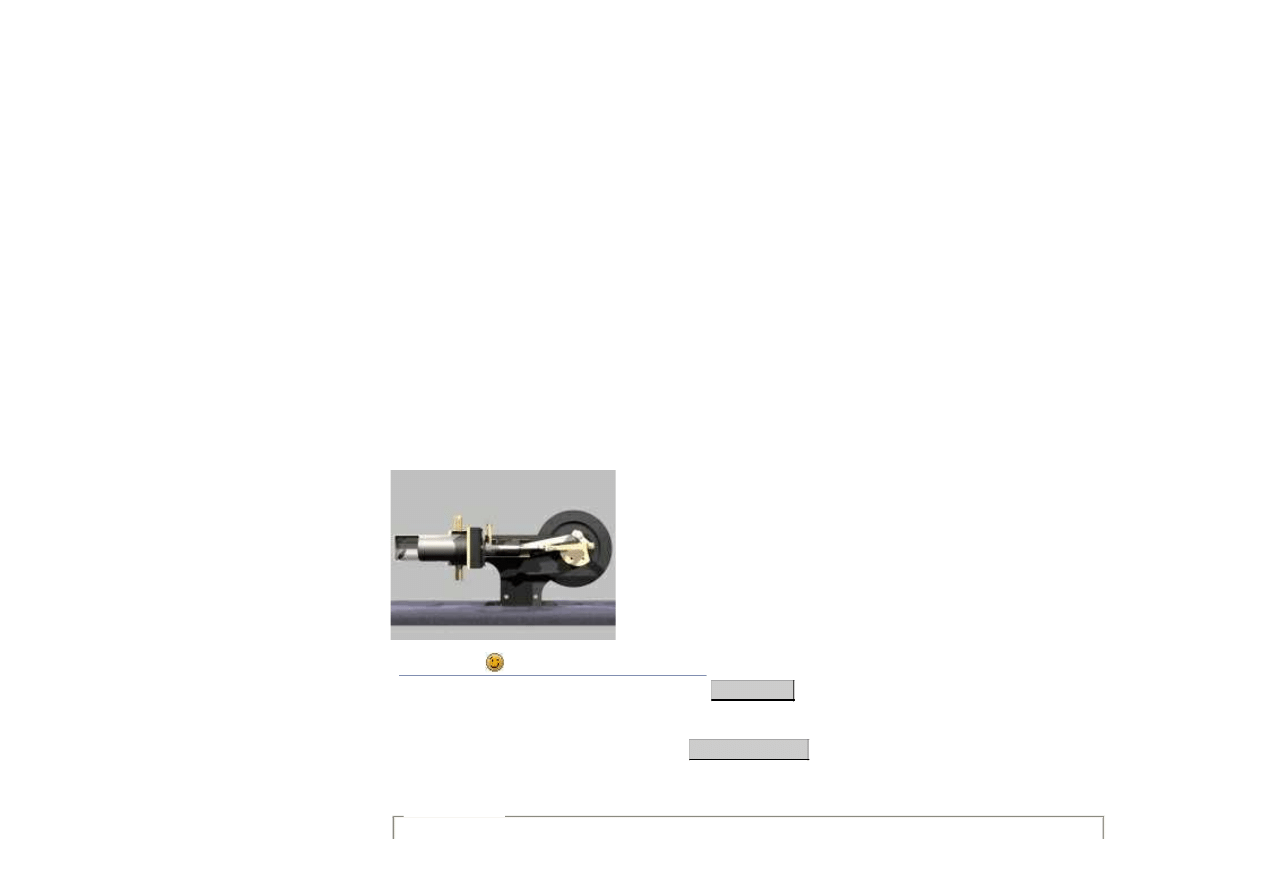
The engine in the photo uses the solid piston, it was quick to make and certainly runs OK but it is grossly
overweight and the vibration probably slows the engine down by several hundred RPM. So, unless you are
really in a hurry, the lightweight piston is recommended; altho' it is more complicated, each individual
operation is inherently simple. Begin with the shell, boring 1/4" over length to the finished I/D and then
turning the O/D, also over length, to within a few thou's of cylinder bore size. (by this time, folk with worn
lathes should have set the top-slide to turn truly parallel) Now advance the cross-slide, a thou' at a time,
reducing just the end 1/8" of the piston and trying to fit the cylinder over it. After each unsuccessful
attempt, and without adjusting the cross-slide, cut along the full length before trying once more - and
then advancing another thou' and reducing the end 1/8" again. As soon as this 1/8" enters the bore take
no further cuts with the tool but remove the last thou' using (in order of preference) a diamond file, an
oilstone or an oiled strip of fine emery cloth on a flat strip of metal. Keep the abrasive moving from side to
side and check frequently with the mike to keep things parallel. Aim for a very light push fit in the bore,
but don't lose too much sleep over it, off load, loose pistons work nearly as well! Do be extremely careful
to avoid jamming the cylinder on the piston. When you are satisfied with the fit, turn off the end 1/8" and,
using a pointed tool, turn a series of oil retaining grooves, about five thou's deep and spaced 1/8". Bore
the little recess to take the head disc before parting/sawing off to length. Received wisdom suggests that
loose emery embeds itself in soft metals, so, if you have been using emery cloth, it will do no harm to
scrub the shell thoroughly in petrol, using an old tooth-brush. The head disc can be glued (Loctite) to a
chucking piece and turned to an easy fit in the recess, drilled and countersunk. Use heat to break the

SURREALISTE action - Wiwi - Stirling gamma
http://www.surrealiste.org/modules/wiwimod/index.php?page=Stirling+gamma
8 sur 12
7/12/2006 17:59
chucking piece and turned to an easy fit in the recess, drilled and countersunk. Use heat to break the
glued joint, clean any remaining glue from the back of the disc and ensure that it is both clean and flat,
with the sharp edge removed, before Loctiting it into the piston. More experienced machinists may elect to
make shell/head in one piece, in which case they might, with advantage, reduce wall thickness to about
0.025", and its probably safer to do this after finishing the O/D to the cylinder bore.
The holes to be drilled in the yoke must be at 90 deg's to each other and the easiest way to ensure this is
by starting with a rectangular block of metal. This can be cut from the same stock as the cylinder
mounting block and accurately 'squared up' in the four jaw chuck. After marking out, return it to the chuck
for drilling and tapping. The gudgeon pin hole should be drilled 1/8" (or drilled and reamed) right through,
the nearest metric drill in this case is 3.1mm, approx. 0.003" undersize. Tap the shell fixing screw hole
after you have sawn/filed out the slot for the con-rod; noting that this will need to be 3/16" wide for the
steel con-rod. Finally, saw and file to the outside shape.
Crankshaft Sheet 8
Begin by marking out, drilling, tapping and then cutting out the disc. To turn the edge of the disc I
chucked a short stub of steel, turned it down to 3/16" dia and threaded it to match the disc. A thick
washer was slipped over it and the disc screwed on to hold the washer firmly against the chuck jaws.
Next, chuck the 3/16" silver steel shaft and thread it. Screw on a nut, as far as it will go, and face it down
to a bare 1/8" thick before putting a dab of Loctite on the projecting thread, screwing the disc on to it and
facing back any remaining thread flush with the face of the disc. This face should now run true. If it
doesn't you will have to correct it by a very light facing cut using an extremely sharp, pointed tool,
removing any tool marks afterwards by rubbing the disc on a sheet of abrasive paper laid on a flat surface.
Use a 1/4" drill held in the fingers to very lightly countersink the crank pin hole to accommodate the small
fillet on the pin.
Its not a bad idea to check the geometrical accuracy of the bed at this stage. Slip the shaft into its
bearings and lay the edge of a steel rule across the face of the disc. The squared end of the ruler should fit
perfectly against the front surface of the mounting block. If it doesn't, turn the crank 180 degrees and try
again. If this reverses the error, the face of the disc must be re-machined. If not, either the block or the
bearing tube is slightly askew, correct by carefully bending the bed, without straining the block fixing
screws.
Finally, saw the disc to shape as shown, and I found the lead balance weight a useful addition to reduce
vibration.
Con-rod Sheet 10 and 11
The steel con-rod is a much better looking job, the engine will run quieter and the split big-end will allow
wear to be taken up. However the long bearing can cause binding and it is not recommended unless you
are 100% confident of the alignment of all your previous work. The spacers, item 29 will not be required.
Otherwise, fit the simple aluminium rod, with the spacers, which can accommodate minor errors without
too much difficulty - and you can always change to the steel rod later if you think the performance justifies
it. To keep the working pressure of a Stirling as high as possible, "dead space" must be kept to the
minimum and the length of rod shown should keep the piston clearance at TDC down to 1/32". However,
any clearance, from a few thou's up to 1/16" is acceptable. Outside these limits it may be possible to
correct by slotting the block fixing screw holes in the bed. If not, you will have to make a new rod after
very carefully measuring between the crank pin and the gudgeon pin with the piston sitting on a 1/32"
spacer against the block. Both holes should be reamed to give a quieter running engine. (initially!)
However, Fizgig is no lady and, being double acting, will hammer her bearings at an alarming rate; by now

SURREALISTE action - Wiwi - Stirling gamma
http://www.surrealiste.org/modules/wiwimod/index.php?page=Stirling+gamma
9 sur 12
7/12/2006 17:59
However, Fizgig is no lady and, being double acting, will hammer her bearings at an alarming rate; by now
you will be impatient to see results and drilled holes work just as well.
Return Crank Sheet 8
If everything were made precisely to the given dimensions, this crank would result in a phase angle of
approx' 95 deg's; roughly in the middle of a very wide range of angles over which there would be no
detectable difference in performance. So don't worry.
Displacer Con-rod Sheet 11
Use aluminium strip and double over at the "big-end" before drilling, to give a larger bearing surface. The
long thread in the knuckle joint is to give help in obtaining the correct clearances at either end of the
displacer stroke. If you still can't get them right you'll have to make another con-rod ------
Flywheel Sheets 13 and 14
Being a double acting engine, i.e. non-snifting, Fizgig works happily with any flywheel you care to hang on
it. In fact the prototypes run at high speed with no flywheel at all! A simple wheel, spoked or not, around
3 1/2" diameter and secured by the traditional grub screw is all that is needed, although Sheet 13 shows
my own favourite method of fixing, as used on the prototypes. The pulley may only be wishful thinking -
keep your fingers crossed. Sheet 14 shows a much simpler lead flywheel. The large diameter boss is to
allow for a long grub screw to reduce the risk of stripping the thread in the soft metal.
Assembly
With a mean working pressure of less than 4 PSI it is essential that our engine runs with the absolute
minimum friction, and this includes oil drag. The lovely silky smooth feel of a well made steam engine
which "ticks over beautifully at only 5 PSI" simply won't do for a Stirling engine. Our aim must be an
engine which feels "loose" albeit, ideally, with no perceptible play in any of the bearings. Or, if we can't
quite achieve this, "loose" with the minimum play. The first requirement is accurate alignment and the
earlier check should have ensured that the cylinder is square with the crankshaft. Assemble the piston and
con-rod, smother with Molyslip and slide it into the cylinder. Use more Moly to insert the crank-shaft into
its bearings but don't oil the crank pin before sliding the big-end on and screwing the cylinder to the block
with a couple of lengths of 7BA studding. Now turn the shaft over and check that the big-end is sitting
about 3/32" from the crank disc and is perfectly free to slide, although perhaps only 1/32", sideways
throughout a whole revolution. If it isn't and binds slightly, turn the cylinder upside-down and try again. If
this doesn't do the trick, turn the rod over, or the piston etc etc. If you can't find an ideal combination,
then settle for the best and, with luck, any tightness will disappear after the running in.
This may well be required anyway. So now unscrew the cylinder to remove the big-end from the pin and
fit one of the spacers before replacing it. Molyslip the pin, slip the other spacer on and fit the return crank
to allow a few thou's side play at the big-end. Refit the cylinder and check that the shaft turns freely -
(hopefully now with that silky smooth feeling!) couple up to the lathe or similar and motor the engine at
several hundred RPM for 5 mins or so. Now strip the engine, use a dry clean rag to clean the Molyslip and
all traces of oil from the cylinder and piston, and reassemble. Without the air chamber fitted it should be
possible to twirl the crankshaft freely with finger and thumb. A single drop of light oil should now keep the
piston happy, clock, sewing machine, typewriter or thin cycle oil will do but don't use motor oil or WD40.
Re-fit the return crank, setting the clamping screw so that it can be easily turned on the crankpin with
light finger pressure and set it to approx' the angle shown on Sheet 14 Use the same light oil on the
displacer rod before sliding it into its bushes and couple it up to its con-rod/crank-pin. Hold the air
SURREALISTE action - Wiwi - Stirling gamma
http://www.surrealiste.org/modules/wiwimod/index.php?page=Stirling+gamma
10 sur 12
7/12/2006 17:59
displacer rod before sliding it into its bushes and couple it up to its con-rod/crank-pin. Hold the air
chamber in place and adjust the length of the displacer rod together with the throw of the return crank to
give about 1/64" clearance at the hot end of the chamber and 1/32" clearance at the cold end. Tighten the
return crank clamping screw and the air chamber may now be screwed to the block with two more lengths
of 7BA studding, using an oiled paper gasket to seal it.
As a final check, and to delay the dreaded moment of truth for a few more minutes, hold the chamber and
both joints under hot water and turn the crank to TDC. Any bubbles appearing at the joints should be
investigated before proceeding any further.
The first run of any hot air engine is always a special occasion. (perhaps best attempted in seclusion!) The
great Dr Stirling himself probably knew the same apprehension as things warmed up, and the same
feeling of amazement when it actually ran! Clamp Fizgig's bed in the vice and apply a small torch flame to
the side of the heater. Turn the crank a few times to distribute the heat along the displacer and then give
it a flick in the forward direction - i.e., that in which the displacer leads the piston. At the third or fourth
flick the engine should keep running and within 25 to 30 seconds it should reach 1500 RPM or so. Keep
your hand on the jacket and as soon as it becomes really warm, 30 to 40 seconds, remove the flame.
If all is successful, fit the engine to a baseboard with a water tank and connect this up to the stubs on the
jacket. Note the bottom stub is shorter to reduce the sharpness of the bend in the plastic pipe. Fill the
tank with water and, fired by a simple spirit/alcohol lamp, the engine should run indefinitely ------
Finally, I must apologise for the nit-picking detail in this text. Most hot air engine builders will admit to
having built the occasional dud and I can certainly claim to have built my share. These failures (my own
and others) were sometimes due to a silly little detail and I have attempted to recall and overcome these
and forestall others in this write-up.
Bon bricolage
mis à jour le : 30.05.05 par
Matt Lechien
Commentaires

SURREALISTE action - Wiwi - Stirling gamma
http://www.surrealiste.org/modules/wiwimod/index.php?page=Stirling+gamma
11 sur 12
7/12/2006 17:59
Auteur
Conversation
tatui
Posté le: 23/11/2005 16:26 Mis à jour: 24/11/2005 12:26
Guérillero vert
Inscrit le: 27/7/2005
De:
Envois: 35
Re: Stirling gamma
j'ai commencé à traduire (1 paragraphe 1/2...) mais il manque quelques
termes techniques, que j'ai signalés par (?...) si quelqu'un veut participer!!!
Découper le châssis dans une feuille d'acier (?mild steel = acier avec 10 à 25
% de carbonne?) de 2mm ou 3mm (1/10" ou 1/8") d' épaisseur, et si vous ne
parvenez pas à trouver localement un morceau d'acier qui convienne, notez
que les firmes qui fournissent l'acier (?frame steel?) aux constructeurs de
locomotives miniatures peuvent vous procurer du materiau de 3mm. Si vous
avez l'intention de faire le (?con-rod?) avec le (?split big-end?) il est essentiel
que la tige du piston soit vraiment perpendiculaire au vilebrequin et pour celà
il faut que la plaque de fond soit plate. Verifiez celà avant de le delimiter en
enlevant d'abord les éventuelles bavures des bords et en le tenant à la
lumière avec une règle d'acier plaquée d'un bout à l'autre de la surface. Sur la
face concave vous verrez un faisceau de lumière entre la règle et le metal et
c'est sur cette face que vous devrez marquer les limites. Percez les trous
d'abord, la correspondance entre les trous du support et les trous de vissage
du bloc étant particulièrement important. Découper alors la forme exterieure
du châssis. Ceci est pour l'esthetique uniquement et n'est donc pas crucial,
que vous utilisiez une scie sauteuse en ponçant ensuite ou bien une meuleuse,
c'est votre choix. La tâche suivant est de faire de cette surface concave une
surface plate, et après avoir enlevé les éventuelles bavures sur les bords,
quelques coups de papier à poncer neuf devraient suffir.
Vilebrequin portant (?bearing tube sheet?) 2a
il est important que la collerette soit ajustée précisément au trou au centre du
tube et ceci ne présentera aucune difficulté pour le tourneur expérimenté avec
un équipement à moitié correct. Pourtant les débutants ont souvent des
difficultés à percer de longs trous avec précision, et la combinaison : forêt
inadéquatement affûté + poupée mobile imparfaitement alignée peut rendre
la chose très difficile. Alors sauf si vous êtes vraiment sûr de vous, (?chuck
the rod?) et percez le trou d'abord, en commençant exactement au centre du
côté de la collerette. Puis enlevez-le (?la?) du (?chuck?) et faites un
(?mandrel?) pour le monter dessus. (? Chuck a length of 3/8" dia mild steel
with about 3/4" protruding and turn this down to a few thous (thousandths of
an inch) over 9/32" dia?) puis utilisez un papier à poncer très fin pour mettre
(?a taper = une mèche?) très légère dessus, pour que le tube, côté colerette
en premier, force juste sur 1/2". Mettre plein d'huile dans le tube avant de
maintenir l'extrémité exterieure du tube avec la poupée mobile, puis (?turn
down = abaisser? Enfoncer?) l'exterieur du tube à 3/8" (?dia?), en laissant
une épaisseur de collerette de 1/16". Couper ce côté de la collerette d'un
geste franc pour le laisser net.

SURREALISTE action - Wiwi - Stirling gamma
http://www.surrealiste.org/modules/wiwimod/index.php?page=Stirling+gamma
12 sur 12
7/12/2006 17:59
geste franc pour le laisser net.
commentaire du traducteur: waille ça devient difficile...
Wyszukiwarka
Podobne podstrony:
Motore Stirling Fabriquer un moteur Stirling à partir d un Briggs & Stratton
Faire Du Froid Moteur Stirling
Moteur Stirling solaire 3 2
Moth Rep Le moteur Stirling
moteur stirling
Moteur Stirling générateur de courant
Projet? tracteur à moteur Stirling
Faire Du Froid Moteur Stirling
Cogénération Moteur Stirling
Moteur Stirling à eau
Moteur Stirling Solaire Version 3 4
Moteur Stirling générateur de courant à faible gradient de température 3 7
[Engine] Moteur Stirling simplifié
Les avantages et les inconvénients moteur stirling
Optimisation thermodynamique en temps fini du moteur de Stirling endo et exo irreversible
więcej podobnych podstron