
SAFETY HANDBOOK
B--80687EN/03
E
FANUC LTD, 1996

Table of Contents
B--80687EN/03
i
GENERAL PRECAUTIONS
1
. . . . . . . . . . . . . . . . . . . . . . . . . . . . . . . . . . . . . . . . . . . . . . . . . . . . .
Chapter 1
FANUC ROBOT SYSTEM
3
. . . . . . . . . . . . . . . . . . . . . . . . . . . . . . . . . . . . . . . . . . . . . . . . . . . . . .
1.1 PURPOSE OF ROBOT
3
. . . . . . . . . . . . . . . . . . . . . . . . . . . . . . . . . . . . . . . . . . . . . . . . . . . . . . . .
1.2 CONFIGURATION OF ROBOT SYSTEM
5
. . . . . . . . . . . . . . . . . . . . . . . . . . . . . . . . . . . . . . . .
1.3 WORKING PERSON
6
. . . . . . . . . . . . . . . . . . . . . . . . . . . . . . . . . . . . . . . . . . . . . . . . . . . . . . . . .
1.3.1 Robot Training
7
. . . . . . . . . . . . . . . . . . . . . . . . . . . . . . . . . . . . . . . . . . . . . . . . . . . . . . . . . . . . .
Chapter 2
ROBOT SYSTEM DESIGN
9
. . . . . . . . . . . . . . . . . . . . . . . . . . . . . . . . . . . . . . . . . . . . . . . . . . . . . .
2.1 GENERAL
9
. . . . . . . . . . . . . . . . . . . . . . . . . . . . . . . . . . . . . . . . . . . . . . . . . . . . . . . . . . . . . . . . .
2.2 PLACEMENT OF EQUIPMENT
9
. . . . . . . . . . . . . . . . . . . . . . . . . . . . . . . . . . . . . . . . . . . . . . . .
2.3 POWER SUPPLY AND PROTECTIVE EARTH CONNECTION
11
. . . . . . . . . . . . . . . . . . . . . .
2.4 OTHER PRECAUTIONS
11
. . . . . . . . . . . . . . . . . . . . . . . . . . . . . . . . . . . . . . . . . . . . . . . . . . . . . .
2.5 END EFFECTOR, WORKPIECE AND PERIPHERAL EQUIPMENT
14
. . . . . . . . . . . . . . . . . .
Chapter 3
SAFETY DEVICES
17
. . . . . . . . . . . . . . . . . . . . . . . . . . . . . . . . . . . . . . . . . . . . . . . . . . . . . . . . . . . .
3.1 EMERGENCY STOP
17
. . . . . . . . . . . . . . . . . . . . . . . . . . . . . . . . . . . . . . . . . . . . . . . . . . . . . . . . .
3.2 MODE SELECT SWITCH
17
. . . . . . . . . . . . . . . . . . . . . . . . . . . . . . . . . . . . . . . . . . . . . . . . . . . . .
3.2.1 Operating Modes
20
. . . . . . . . . . . . . . . . . . . . . . . . . . . . . . . . . . . . . . . . . . . . . . . . . . . . . . . . . . .
3.3 DEADMAN SWITCH
20
. . . . . . . . . . . . . . . . . . . . . . . . . . . . . . . . . . . . . . . . . . . . . . . . . . . . . . . .
3.4 SAFEGUARDS
21
. . . . . . . . . . . . . . . . . . . . . . . . . . . . . . . . . . . . . . . . . . . . . . . . . . . . . . . . . . . . . .
3.4.1 Safety Fence
21
. . . . . . . . . . . . . . . . . . . . . . . . . . . . . . . . . . . . . . . . . . . . . . . . . . . . . . . . . . . . . . .
3.4.2 Safety Gate and Plugs
21
. . . . . . . . . . . . . . . . . . . . . . . . . . . . . . . . . . . . . . . . . . . . . . . . . . . . . . .
3.4.3 Other Protection Devices
22
. . . . . . . . . . . . . . . . . . . . . . . . . . . . . . . . . . . . . . . . . . . . . . . . . . . . .
3.5 THE SAFETY SEQUENCE FOR FENCE ENTRY
23
. . . . . . . . . . . . . . . . . . . . . . . . . . . . . . . . .
3.6 ROBOT STOP VARIATION
25
. . . . . . . . . . . . . . . . . . . . . . . . . . . . . . . . . . . . . . . . . . . . . . . . . . .
Chapter 4
GENERAL CAUTIONS
27
. . . . . . . . . . . . . . . . . . . . . . . . . . . . . . . . . . . . . . . . . . . . . . . . . . . . . . . . .
4.1 INSTALLATION
27
. . . . . . . . . . . . . . . . . . . . . . . . . . . . . . . . . . . . . . . . . . . . . . . . . . . . . . . . . . . . .
4.2 COMMISSIONING AND FUNCTIONAL TESTING
27
. . . . . . . . . . . . . . . . . . . . . . . . . . . . . . . .
4.2.1 Designation of the Restricted Space
27
. . . . . . . . . . . . . . . . . . . . . . . . . . . . . . . . . . . . . . . . . . . . .
4.2.2 Restriction of Personnel
28
. . . . . . . . . . . . . . . . . . . . . . . . . . . . . . . . . . . . . . . . . . . . . . . . . . . . . .
4.2.3 Safety and Operational Verification
28
. . . . . . . . . . . . . . . . . . . . . . . . . . . . . . . . . . . . . . . . . . . . .
4.2.4 Robot System Restart Procedures
28
. . . . . . . . . . . . . . . . . . . . . . . . . . . . . . . . . . . . . . . . . . . . . .
4.3 PROGRAMMING
29
. . . . . . . . . . . . . . . . . . . . . . . . . . . . . . . . . . . . . . . . . . . . . . . . . . . . . . . . . . . .
4.3.1 Prior to Programming
29
. . . . . . . . . . . . . . . . . . . . . . . . . . . . . . . . . . . . . . . . . . . . . . . . . . . . . . . .

TABLE OF CONTENTS
B--80687EN/03
ii
4.3.2 During Programming
29
. . . . . . . . . . . . . . . . . . . . . . . . . . . . . . . . . . . . . . . . . . . . . . . . . . . . . . . .
4.3.3 Returning to Automatic Operation
29
. . . . . . . . . . . . . . . . . . . . . . . . . . . . . . . . . . . . . . . . . . . . . .
4.4 PROGRAM VERIFICATION
30
. . . . . . . . . . . . . . . . . . . . . . . . . . . . . . . . . . . . . . . . . . . . . . . . . . .
4.5 TROUBLE SHOOTING
30
. . . . . . . . . . . . . . . . . . . . . . . . . . . . . . . . . . . . . . . . . . . . . . . . . . . . . . .
4.6 SAVING PROGRAMMED DATA
30
. . . . . . . . . . . . . . . . . . . . . . . . . . . . . . . . . . . . . . . . . . . . . . .
4.7 AUTOMATIC OPERATION
30
. . . . . . . . . . . . . . . . . . . . . . . . . . . . . . . . . . . . . . . . . . . . . . . . . . .
4.8 MAINTENANCE
31
. . . . . . . . . . . . . . . . . . . . . . . . . . . . . . . . . . . . . . . . . . . . . . . . . . . . . . . . . . . .
4.9 OTHER CAUTIONS
32
. . . . . . . . . . . . . . . . . . . . . . . . . . . . . . . . . . . . . . . . . . . . . . . . . . . . . . . . .
Chapter 5
DAILY MAINTENANCE
33
. . . . . . . . . . . . . . . . . . . . . . . . . . . . . . . . . . . . . . . . . . . . . . . . . . . . . . . .
5.1 MECHANICAL UNIT
33
. . . . . . . . . . . . . . . . . . . . . . . . . . . . . . . . . . . . . . . . . . . . . . . . . . . . . . . .
5.1.1 Before Powering On
33
. . . . . . . . . . . . . . . . . . . . . . . . . . . . . . . . . . . . . . . . . . . . . . . . . . . . . . . . .
5.1.2 After Automatic Operation
33
. . . . . . . . . . . . . . . . . . . . . . . . . . . . . . . . . . . . . . . . . . . . . . . . . . . .
5.2 CONTROL UNIT
34
. . . . . . . . . . . . . . . . . . . . . . . . . . . . . . . . . . . . . . . . . . . . . . . . . . . . . . . . . . . .
Appendix A
CONTACTS
35
. . . . . . . . . . . . . . . . . . . . . . . . . . . . . . . . . . . . . . . . . . . . . . . . . . . . . . . . . . . . . . . . . . .
Appendix B
MANUFACTURER LABEL
37
. . . . . . . . . . . . . . . . . . . . . . . . . . . . . . . . . . . . . . . . . . . . . . . . . . . . .
Appendix C
CAUTION LABELS
43
. . . . . . . . . . . . . . . . . . . . . . . . . . . . . . . . . . . . . . . . . . . . . . . . . . . . . . . . . . . .

1
GENERAL CAUTIONS
B--80687EN/03
4
In this chapter, the requirements for safety during the following situations.
D
Installation (1.1)
D
commissioning and functional testing (1.2)
D
programming (1.3)
D
program verification (1.4)
D
trouble shooting (1.5)
D
saving programmed data (1.6)
D
automatic operation (1.7)
D
maintenance (1.8)
D
other cautions (1.9)
The user must ensure that the safeguarding methods are provided, utilized,
and maintained for each operation associated with the robot system and in
particular for personnel other than those utilizing the teach pendant or
enabling device.
The user must ensure that a teach pendant not connected to the robot
controller must be inaccessible.
Note that the motors of the robot may have heated just after its movement.
Please be careful not to touch them, if possible. If it is needed to touch the
motors for maintenance, etc., care should be taken in touching them.
The robot system must be installed in accordance with FANUC’s
requirements. The safeguarding methods must be identified by the hazard
analysis and the risk assessment. The user must review the safety
requirements to ensure that the appropriate safeguards are applied and
operational prior to use in production.
During the testing of robots or robot systems after installation or
relocation, the following procedures must be followed. These procedures
are also applied to robots or robot systems after modifications (e.g.
changes in hardware or software, replacement of parts, adjustments) and
after maintenance or repairs that can adversely affect their operation.
When the safeguarding methods are not in place prior to commissioning
and functional testing, interim means of designating the restricted space
must be in place before proceeding.
1.1
INSTALLATION
1.2
COMMISSIONING AND
FUNCTIONAL TESTING
1.2.1
Designation of the
Restricted Space

B--80687EN/03
5
1. GENERAL CAUTIONS
During the commissioning and functional testing, personnel must not be
allowed in the safeguarded space until the safeguards are functional.
At the initial start--up, the following procedure must be included (but not
limited to). Before applying power, verify that
D
the robot has been properly mechanically mounted and is stable,
D
the electrical connections are correct and that the power (i.e. voltage,
frequency, interference levels) is within specified limits,
D
the other utilities (e.g. water, air, gas) are properly connected and
within specified limits,
D
the peripheral equipment is properly connected,
D
the limiting devices that establish the restricted space (when utilized)
are installed,
D
the safeguarding means are applied, and
D
the physical environment is as specified (e.g. lighting and noise levels,
temperature, humidity, atmospheric contaminants).
After applying power, verify that
D
the start, stop, and mode selection (including key lock switches)
control devices function as intended,
D
each axis moves and is restricted as intended,
D
emergency stop circuits and devices are functional,
D
it is possible to disconnect and isolate the external power sources,
D
the teach and playback facilities function correctly,
D
the safeguards and interlocks function as intended,
D
other safeguarding is in place (e.g. barriers, warning devices),
D
in reduced speed, the robot operates properly and has the capability to
handle the product or workpiece, and
D
in automatic (normal) operation, the robot operates properly and has
the capability to perform the intended task at the rated speed and load.
A procedure for the restart of the robot system after hardware, software or
task program modification, repair, or maintenance must include but not
necessarily be limited to the following:
D
check any changes or additions to the hardware prior to applying
power;
D
functionally test the robot system for proper operation.
1.2.2
Restriction of
Personnel
1.2.3
Safety and Operational
Verification
1.2.4
Robot System Restart
Procedures

B--80687EN/03
6
1. GENERAL CAUTIONS
Whenever possible, programming must be performed with all persons
outside the safeguarded space. When it is necessary to perform
programming with personnel inside the safeguarded space, the following
safety procedures are necessary.
The programmer must be trained on the type of robot used in the actual
robot system and must be familiar with the recommended programming
procedures including all of the safeguarding methods.
D
The programmer must visually check the robot system and safeguarded
space to ensure that extraneous conditions which can cause hazardous
do not exist.
D
Where required for programming, the teach pendant must be tested to
ensure proper operation.
D
Any faults or failures must be corrected prior to entering the
safeguarded space.
Before entering the safeguarded space, the programmer must ensure that all
necessary safeguards are in place and functioning.
The programmer must set the operating mode T1 (or T2) from AUTO prior
to entering the safeguarded space.
During programming, only the programmer must be allowed in the
safeguarded space and the following conditions must be met.
D
The robot system must be under the sole control of the programmer
within the safeguarded space. (When T1 or T2 mode is selected, the
robot can be moved only by the teach pendant.)
D
The controls of the teach pendant must be used as intended.
D
The robot system must not respond to any remote commands or
conditions that would cause hazardous conditions.
D
Movement of other equipment in the safeguarded space which can
present a hazard must either be prevented or under the sole control of
the programmer. When under control of the programmer, it must
require deliberate action on the part of the programmer separate from
the action to initiate robot motion.
D
All robot system emergency stop devices must remain functional.
The programmer must return the suspended safeguards to their original
effectiveness prior to initiating automatic operation of the robot system.
1.3
PROGRAMMING
1.3.1
Prior to Programming
1.3.2
During Programming
1.3.3
Returning to Automatic
Operation

B--80687EN/03
7
1. GENERAL CAUTIONS
When visual examination of the robot system response to the task program
is necessary as part of the verification procedure, it should be made with all
persons outside the safeguarded space. When it is necessary to perform
program verification with personnel inside the safeguarded space, the
following must apply.
D
Program verification must initially be performed at reduced speed.
D
When it is necessary to examine the movement of the robot at full
(operational) speed, the following requirements must apply:
--
suspension of the reduced speed by the operation mode switch (T2
mode) must be done by the programmer only;
--
an enabling device or a device with an equivalent safety level must
be used by personnel within the safeguarded space;
--
safe working procedures are established to minimize the exposure
of personnel to hazards within the safeguarded space.
Trouble shooting must be performed from outside the safeguarded space.
When this is not practicable, and the design of the robot system has taken
into account the necessity of performing trouble shooting from within the
safeguarded space, the following requirements must apply:
D
personnel responsible for trouble shooting are specifically authorized
and trained for these activities;
D
personnel entering the safeguarded space must use the teach pendant
(deadman switch) to allow motion of the robot;
D
safe working procedures are established to minimize the exposure of
personnel to hazards within the safeguarded space.
Whenever possible, a record of the task programs together with any
modifications should be maintained.
Programmed data can be stored on a floppy disk. The floppy disk must be
stored in a suitably protected environment when not in use.
Please refer to ”Setup and Operations Manual” for storing a data to a
floppy disk.
Automatic operation must only be permissible when
D
the intended safeguards are in place and functioning,
D
no personnel are present within the safeguarded space, and
D
proper safe working procedures are followed.
1.4
PROGRAM
VERIFICATION
1.5
TROUBLE SHOOTING
1.6
SAVING
PROGRAMMED DATA
1.7
AUTOMATIC
OPERATION

B--80687EN/03
8
1. GENERAL CAUTIONS
The robot system must have an inspection and maintenance program to
ensure continued safe operation of the robot system. The inspection and
maintenance program must take into account the robot and robot system
manufacturer’s recommendations.
Personnel who perform maintenance or repair on robots or robot system
must be trained in the procedures necessary to perform safely the required
tasks.
Personnel who maintain and repair robot systems must be safeguarded
from hazards.
Where possible, maintenance must be performed from outside the
safeguarded space by placing the robot arm in a predetermined position.
The following is the safety procedure of entering into safeguarded space
for maintenance when it is necessary to perform maintenance within the
safeguarded space.
Procedure 1
Entering safeguarded space for maintenance
1 Stop the robot system.
2 Shut off the power of the robot system, and lock the main breaker to
prevent powering on during maintenance working, by mistake.
If you have to enter the safeguarded space while power is available to
the robot system, you must do the following things prior to entering
the safeguarded space:
--
check the robot system to determine if any conditions exist that are
likely to cause malfunctions,
--
check if the teach pendant works correctly, and
--
if any damage or malfunction is found, complete the required
corrections and perform retest before personnel enter the
safeguarded space.
3 Enter the safeguarded space (see 3.5 ”The Safety Sequence for Fence
Entry”).
4 After the maintenance working, check if the safeguard system is
effective. If it has been suspended to perform the maintenance
working, return their original effectiveness.
1.8
MAINTENANCE
Step

B--80687EN/03
9
1. GENERAL CAUTIONS
D
Some robot models have some axes without brakes which prevents
moving during their power being cut off. So their axes without brakes
may be moved by the force of gravity when:
--
cut off the power of the robot, and
--
stop the robot by an emergency stop.
Please be careful of their movement, especially for their wrist joints,
in the above operations. For details, refer to the maintenance manual
for each robot model.
1.9
OTHER CAUTIONS

2
ROBOT SYSTEM DESIGN
B--80687EN/03
9
In this chapter, requirements for robot system design are described.
--
Placement of Equipment
--
Power Supply and Protective Earth Connection
--
Other Precautions
In addition, the basic requirements for end effector, workpiece, and
peripheral equipment are outlined in 2.5.
About safety fence, safety gate and other protection devices, please refer to
3.4 and 3.5.
The robot system must be designed, constructed, and implemented so that
in case of a foreseeable failure of any single component, whether electrical,
electronic, mechanical, pneumatic, or hydraulic, safety functions are not
affected or when they are, the robot system is left in a safe condition
(”Failure to safety”).
The application of the electrical equipment of the robot system must be
accordance with EN60204--1.
Please make sure the following requirements are all satisfied for each
component of a robot system.
D
Appropriate safety fence/guard must be placed according to EN775
and Annex I of Machine Directive. Please refer to section 3.4 and 3.5
for the requirement of the safety fence/guard and protection devices.
D
The risk assessment must determine the additional space required
beyond the restricted space to define the safeguarded space.
D
The operator panel must be located at a safe place:
--
outside the safety fence, and cannot be reached from inside the
safety fence,
--
where it can be easily seen, and easily operated by the operator,
--
where the operator can operate it without hesitation or loss of time
and without ambiguity, and
--
where no dangerous situation is created by operating it.
D
Large space must be secured around each component enough for the
maintenance and inspection of the system.
2.1
GENERAL
2.2
PLACEMENT OF
EQUIPMENT

B--80687EN/03
10
2. ROBOT SYSTEM DESIGN
D
A stable scaffold must be provided, wherever necessary, for the
maintenance and inspection of the system.
D
The space inside the safety fence, especially for maintenance and
inspection, must be designed to protect the operator from falling off or
slipping off the step.
D
The robot system must be secured on a stable floor. Especially the
robot mechanical unit must be attached to the floor according to the
instructions in the maintenance manual.
D
Robot systems must be designed to avoid trapping and collision
between the moving parts of the robot and other fixed or moving
objects.
D
The layouts must be designed in such a way that between moving parts
of the robot and objects in the environment (e.g. pillars of the
structure, ceiling joists, fences, supply leads) sufficient clearance is
available.
This rule does not apply to associated equipment in order to allow it to
perform its task.
D
When a limitation of the restricted space, by limiting the range of
motion of the primary axes, is required by the plan, limiting devices
must be provided. They must comply with one of the following.
--
Mechanical stops which are capable of stopping the robot at any
adjusted position when it is carrying its rated load at maximum
velocity.
--
Alternative methods of limiting the range of motion may be
provided only if they are designed, constructed, and installed to
achieve the same level of safety as the mechanical stops.
This may include using the robot controller and limit switches
according to IEC204--1.
Note that the limiting devices must be correctly adjusted and secured.
D
When it is intended that operators will perform manual operations
associated with the robot, such as loading and unloading of parts, this
must be taken into account in the arrangement of the robot system,
either by providing loading devices so that the operator cannot access
the hazardous area, or by providing appropriate safeguards for the
manual activity.

B--80687EN/03
11
2. ROBOT SYSTEM DESIGN
D
The power supply and the grounding must be connected according to
maintenance manual.
--
R--J controller
: B--67995E
--
R--J2 controller
: B--80525E--1
--
R--J2 Mate controller
: B--80465EN--1
--
R--J3 controller
: B--80945EN--1
D
Unsafe conditions must be avoided in the event of a power down,
power recovery after a power down or supply voltage fluctuations.
Unsafe conditions to be avoided are;
--
Dropping workpiece or any material,
--
Safety equipment not functioning, etc..
D
The robot system must have means to isolate its power sources. These
means must be located in such a way that no person will be exposed to
hazardous and the must have a lockout/tagout capability.
D
Shut down (removal of power) to the robot system or any associated
equipment must not result in a hazardous condition.
D
All environmental conditions must be evaluated to ensure
compatibility of the robot and the robot system with the anticipated
operational conditions.
These conditions include, by are not limited to, explosive mixtures,
corrosive conditions, humidity, dust, temperature, electromagnetic
interference (EMI), radio frequency interference (RFI), and vibration.
D
The control position where the operator stands must be predetermined.
The control position must satisfy the following conditions.
--
The operator can easily operate the panel or the teach pendant.
--
The operator can easily make sure that nobody is inside the safety
fence.
--
The operator can easily verify the operation of the system.
--
The operator can immediately stop the entire or partial system in
the event a malfunction of the system or any dangerous condition.
2.3
POWER SUPPLY AND
PROTECTIVE EARTH
CONNECTION
2.4
OTHER PRECAUTIONS

B--80687EN/03
12
2. ROBOT SYSTEM DESIGN
D
The following safety measure must be used if the operator cannot
easily verify nobody is inside the safety fence, or as required by the
risk--assessment result.
--
A visible/audible warning (complying EN standards) is used
before robot starts moving.
--
A measure for the person inside the fence to stop the robot system
or a measure for the person to evacuate outside the fence.
D
The manual intervention and reset procedure to restart the robot system
after an emergency stop must take place outside the restricted space.
D
A warning device must be such that the operator and people in
dangerous area can easily recognize it.
D
The area must be appropriately lighted, especially for maintenance and
inspection.
The lighting must not create a new dangerous situation (e.g. dazzled).
D
It is recommended that adjustment, oiling, and other maintenance work
can be performed from outside the dangerous area while the system is
stopping.
If it is not feasible, a method to perform these operation safely must be
established.
D
If the robot and the peripheral equipment synchronously move in the
robot system, an appropriate measure must be provided to avoid unsafe
condition by stopping the entire system in the event any of the
equipment stops due to malfunction.
D
Any robot that can be controlled from a remote location must be
provided with an effective means that must prevent hazardous
conditions of the robot being initiated from any other location.
D
For robot systems that can be operated from a remote location (e.g.
over a communications network), a means must be provided (e.g. a key
operated switch) to ensure that no commands can initiate hazardous
conditions from the remote location when in local control.

B--80687EN/03
13
2. ROBOT SYSTEM DESIGN
D
It is recognized that for certain phases of the robot system life (e.g.
commissioning, process changeover, cleaning, and maintenance) it
may not be possible to design completely adequate safeguards to
protect against every hazard or that contain safeguards may be
suspended.
Under these conditions, appropriate safe working procedures must be
used.
D
A robot system manufacturer must provide an operation manual
according to EN775 10.2 ”Robot system documentation to be supplied
by the robot system manufacturer”.
D
The requirements in the Machinery directive appendix #1 and EN775
must be considered when a robot application system is designed.

B--80687EN/03
14
2. ROBOT SYSTEM DESIGN
It is the responsibility of the robot system manufacturer to perform the risk
assessment of the end effector, workpiece and the peripheral equipment.
This section outlines the basic requirement for the risk assessment of these
components.
D
End effectors must be designed and constructed, or safeguarded, so
that
--
power failure does not cause release of the load or result in a
hazardous condition, and
--
the static and dynamic forces created by the load and the end
effector together are within the load capacity and dynamic
response of the robot.
D
If it is equipped with a tooling that can function with several different
conditions (speed, etc.), the selection of the condition must be safely
and securely done.
D
The material and its shape must cause no dangerous situation, or safety
measures must be provided.
D
If the workpiece is extreme high or low temperature, safety measures
must be provided to avoid personnel from touching or getting too close
to it.
D
The material and shape must cause no dangerous situation.
D
If any component has possibility to break down during operation, it
must be placed so that it will not scatter in the event it breaks down.
D
Pipes (for liquid/gas) must have enough strength for its internal /
external pressure.
D
Pipes must be secured and protected from the external pressure or
tension.
D
Measures must be provided to avoid dangerous situation due to sudden
movement of the pipe or the high speed flow of material in the event a
pipe is broken.
2.5
END EFFECTOR,
WORKPIECE AND
PERIPHERAL
EQUIPMENT
End Effector
Workpiece
Peripheral Equipment
(including end effector)

B--80687EN/03
15
2. ROBOT SYSTEM DESIGN
D
If a pneumatic device is used, an air valve which shuts off the air
supply to the robot must be installed.
D
If other power source than the electricity (e.g. pneumatic, water, heat)
is used in the system, appropriate risk--assessment must be performed,
and appropriate safety measures must be provided.
D
Safety measures must be provided to avoid swapping of components
that causes unsafe conditions, by
--
design to avoid swapping,
--
indication of necessary information on the parts.
D
Safety measures must be provided to avoid inferior contacts, by
--
design to avoid inferior contacts,
--
displaying the information on the connectors, pipes, cables.
D
Safety measures must be provided to avoid unsafe condition by
touching an extremely high/low temperature parts (if any).
D
Safety measures must be provided to avoid fire or explosion through
sufficient amount of investigation.
D
Vibration and sound noise must be kept minimum considering the
effect to the environment.
D
If a laser equipment is used, the following must be considered.
--
avoid unexpected emission of laser light
--
direct/indirect emission of light must give no harm to the health
--
laser light must give no harm to health during maintenance /
adjustment.

B--80687EN/03
16
2. ROBOT SYSTEM DESIGN
3
SAFETY DEVICES
B--80687EN/03
17
This robot has following emergency stop devices.
D
two emergency stop buttons
( installed on the operator’s panel and the teach pendant)
D
external emergency stop (input signal)
When emergency stop button are pushed, the robot stops immediately in
any cases.
The external emergency stop input signal is input from peripheral devices
(e.g. safety fence , gate).
The signal terminal is inside the operator’s box.
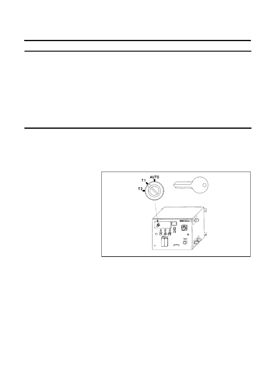
MODE SELECT SWITCH is installed on the operator’s panel. You can
select one of the operation modes using this switch. The selected operation
mode can be locked by removing its key.
When the mode is changed by this switch, the robot system stops and a
message is shown in teach pendant LCD.
Figure 1. Mode Select Switch(R--J2 i cabinet)
3.1
EMERGENCY STOP
3.2
MODE SELECT
SWITCH
B--80687EN/03
18
3. SAFETY DEVICES
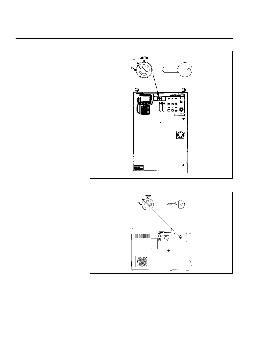
Figure 2. Mode Select Switch(R--J2 B cabinet)
Figure 3. Mode Select Switch(R--J2 Mate)
B--80687EN/03
19
3. SAFETY DEVICES
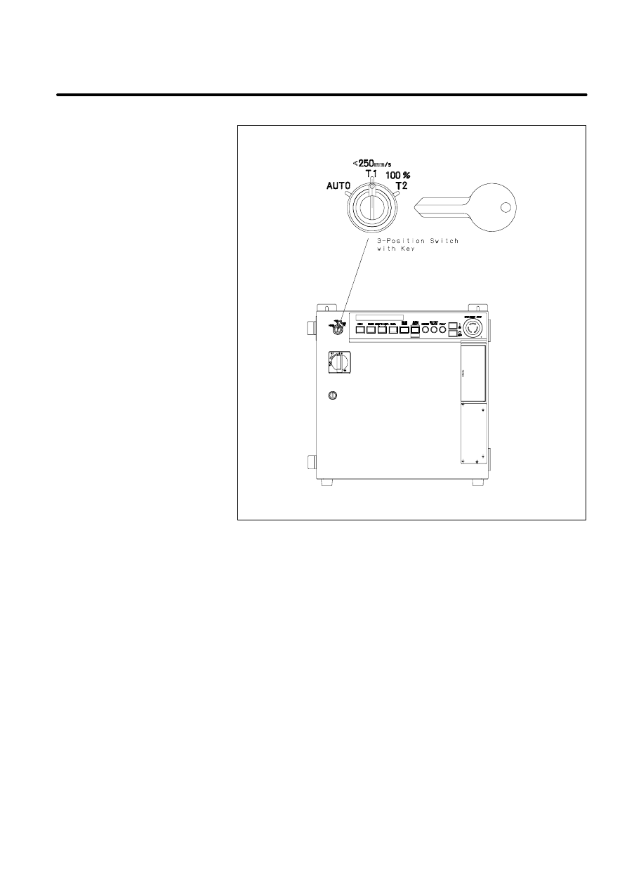
Figure 4. Mode Select Switch(R--J3 i cabinet)
B--80687EN/03
20
3. SAFETY DEVICES
There are three operating modes.
D
The operator’s panel/box becomes enable.
D
The robot program can be started by the operator’s panel/box start
button or peripheral device I/O.
D
Safety fence is enabled.
D
The robot can be operated at the specified maximum speed.
D
Program can be activated from the teach pendant only.
D
The robot cannot be operated at speeds higher than 250mm/sec.
D
Safety fence is disabled.
D
Program can be activated from the teach pendant only.
D
The robot can be operated at the specified maximum speed.
D
Safety fence is disabled.
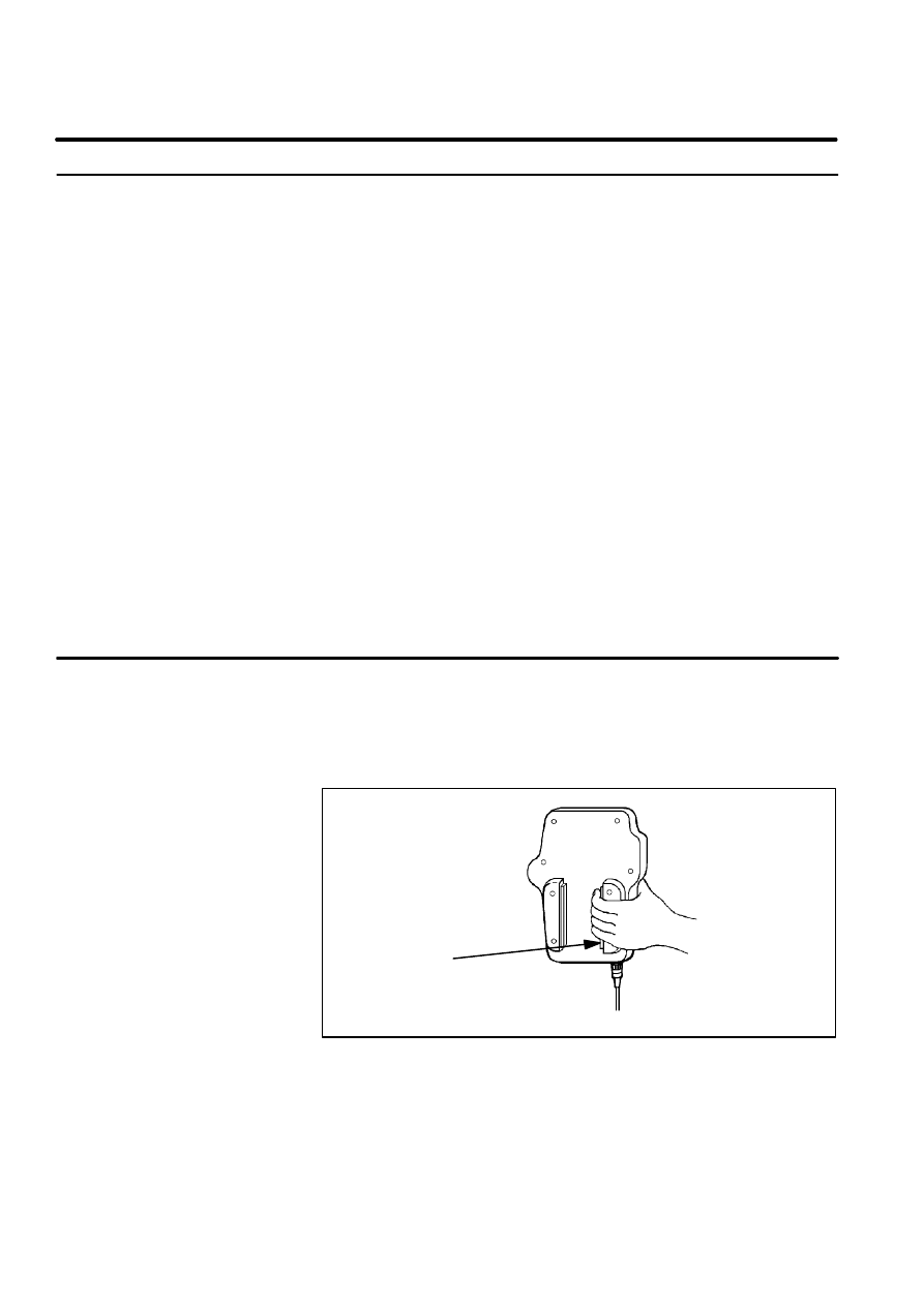
DEADMAN SWITCH is used as an enabling device.
When the teach pendant is enabled, this switch allows robot motion only
while deadman switch is gripped. If you release this switch, the robot stops
immediately.
Figure 5. Deadman Switch
DEADMAN SWITCH
3.2.1
Operating Modes
AUTO: Automatic Mode
T1: Test Mode 1
T2 :Test Mode 2
3.3
DEADMAN SWITCH

B--80687EN/03
21
3. SAFETY DEVICES
The safeguards consists of :
D
safety fence (fixed guard),
D
safety gate (with interlocking devices),
D
safety plug and socket, and
D
other protection devices.
These safety devices must be complied with the EN775 standard.
This section describes the basic requirements for these devices.
Please refer to EN775 standard for detail.
Note that these safety devices must be fitted to the robot system by the
system house, etc..
The requirements for Safety Fence are as follows.
D
The fence is constructed to withstand foreseeable operational and
environmental forces.
D
The fence is free of sharp edges and projection and is not themselves a
hazard.
D
The fence prevent access to the safeguarded space except through
openings associated with interlocking devices.
D
The fence is permanently fixed in position and only be removable with
the aid of a tools.
D
The fence cause minimum obstruction to the view of the production
process.
D
The fence is located at an adequate distance from the maximum space.
D
The fence should be connected to PE(protective Earth) to prevent the
electric shock with accident.
Please refer to EN294, EN349, prEN547 and related standards for detail.
The requirements for Safety Gate are as follows.
D
The gate prevents the robot system from automatic operation until the
gate is closed.
D
The closure of the gate is not the control to restart automatic operation.
This must be a deliberate action at a control station.
D
The gate has plug and socket for interlock.
D
The plug and socket must be selected appropriate things for safety.
3.4
SAFEGUARDS
3.4.1
Safety Fence
3.4.2
Safety Gate and Plugs

B--80687EN/03
22
3. SAFETY DEVICES
This gate must be the one either it remains locked closed until the risk of
injury from the hazard has passed (interlocking guard with guard locking)
or opening the guard while the robot system is working gives a stop or
emergency stop instruction (interlocking guard).
Please refer to prEN1088 and related standards for detail of interlocking
system.
Care should be taken to ensure that actuation of an interlock installed to
protect against on hazard (e.g. stopping hazardous motion of the robot
system) does not create a different hazard (e.g. the release of hazardous
substances into the work zone).
Protection devices must be designed and incorporated into the control
system so that:
D
moving parts cannot start up while they are within the operator’s reach,
D
the exposed person cannot reach moving parts once they have started
up,
D
they can be adjusted only by means of an intentional action, such as
the use of a tool, key, etc.,
D
the absence or failure of one of their components prevents starting or
stops the moving parts.
If some presence sensing devices are used for safety purposes, they must
comply with the following.
D
A presence sensing device must be installed and arranged so that
persons cannot enter and reach into a hazardous area without activating
the device or cannot reach the restricted space before the hazardous
conditions have ceased. Barriers used in conjunction with the presence
sensing device may be required to prevent persons from bypassing the
device.
D
Their operation must not be adversely affected by any of the
environmental conditions for which the system was intended.
D
When a presence sensing device has been activated, it may be possible
to restart the robot system from the stopped position provided that this
does not create other hazards.
D
Resumption of robot motion must require the removal of the sensing
field interruption. This must not be the control to restart automatic
operation.
3.4.3
Other Protection
Devices
B--80687EN/03
23
3. SAFETY DEVICES
This section describes the safety procedure of entering into the safety
fence.
Note that only a programmer or a maintenance person can enter into the
safety fence. A general person CANNOT enter into the safety fence.
Procedure 2
Entering into the SAFETY FENCE
H
The robot is moving automatically (in AUTO mode).
5 Stop the robot.
You can stop the robot:
--
by press emergency switch of operator’s panel or teach pendant
--
by press HOLD button
--
by change to enable with teach pendant enable switch
--
by open SAFETY GATE (pull safety plug)
--
by change mode with operation mode key switch
6 Change the operating mode to T1 or T2 from AUTO.
7 Remove key of operating mode switch for mode lock.
8 Remove the plug2 from socket2.
Open the gate of the safety fence, and put the plug2 to socket4.
9 Remove the plug1 from socket1
10 Enter inside of the safety fence, and put the plug1 to socket3.
Please refer to Figure 6 for details of safety fence and safety plug
configurations.
WARNING
The key of operating mode key switch and the safety plug1
must be carried into the safety fence. The safety plug1
must be put to the socket3 inside fence.
3.5
THE SAFETY
SEQUENCE FOR
FENCE ENTRY
Condition
Step
B--80687EN/03
24
3. SAFETY DEVICES
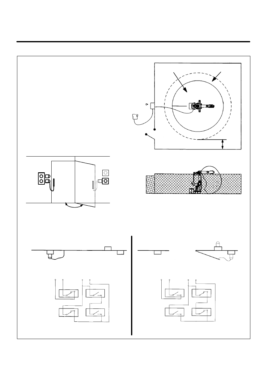
Figure 6. SAFETY FENCE and SAFETY GATE example
Operator’s box
and
mode switch key
Teach pendant
Safety Gate
Safeguard distance
Ristriction space
Maximum space
Safety Fence
Safety Gate
Safety Fence
Safety Gate
Socket 1
Socket 2
plug 1
plug 2
Socket 3
Socket 4
Socket 3
Socket 4
Safety Gate
Safety Fence
Socket 1
Socket 2
plug 1
plug 2
Socket 1
Socket 2
Safety Fence
Safety Gate
Socket 3
Socket 4
plug 1
plug 2
AUTO mode
FENCE1 FENCE2
EMGIN1 EMGIN2
Socket 1
Socket 2
Socket 3
Socket 4
PLUG1
PLUG2
FENCE1 FENCE2
EMGIN1 EMGIN2
T1 / T2 mode
Socket 1
Socket 2
Socket 3
Socket 4
PLUG1
PLUG2
Close
Open
Safety Fence
B--80687EN/03
25
3. SAFETY DEVICES
When emergency stop switch on operator’s panel/box or teach pendant is
pressed, the robot stops immediately.
In other cases (excluding emergency stop switch being pressed), there are
following situations when an emergency stop condition is created by the
combination of operation mode selection, teach pendant enable/disable,
deadman switch, and safety fence open/close.
Table 1. Robot Stop Variations
Mode
TP--Enable
Dead--man
Fence
Status
Auto
enable
grip
open
EMG--stop
g p
close
available
release
open
EMG--stop
close
EMG--stop
disable
grip
open
EMG--stop
g p
close
available
release
open
EMG--stop
close
available
T1/T2
enable
grip
open
available
g p
close
available
release
open
EMG--stop
close
EMG--stop
disable
grip
open
n.a
g p
close
n.a
release
open
EMG--stop
close
EMG--stop
EMG--stop:
Emergency stop
available:
Robot is available
n.a:
Robot is not available
3.6
ROBOT STOP
VARIATION

B--80687EN/03
26
3. SAFETY DEVICES
4
DAILY MAINTENANCE
B--80687EN/03
27
Clean each part, and visually check component parts for damage before
daily system operation.
Check the following items as the occasion demands.
item
check item
check points
1
when air control
set is combined
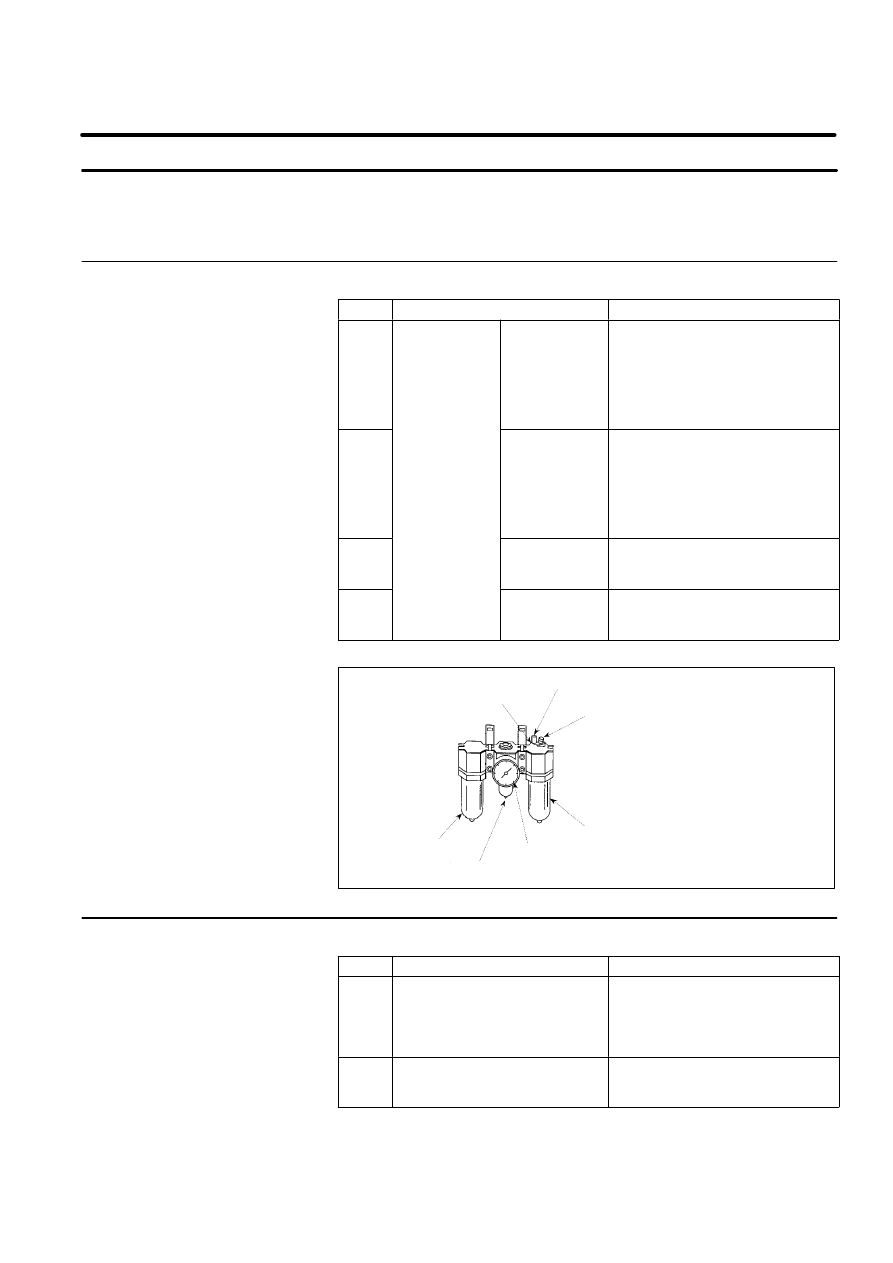
Air pressure
Check air pressure using the
pressure gauge on the air regulator
as shown in Figure 7. If it does not
meet the specified pressure of 5 -- 7
kgf/cm2(0.49 to 0.69MPa), adjust it
using the regulator pressure setting
handle.
2
Oiler oil mist
quantity
Check the drop quantity during wrist
or hand motion. If it does not meet
the specified value (1 drop/10 --
20sec), adjust it using the oiler
control knob. Under normal usage
the oiler becomes empty in about 10
to 20 days under normal operation.
3
Oiler oil level
Check to see that the oiler level is
within the specified level shown in
Figure 7.
4
Leakage from
hose
Check the joints, tubes, etc. for
leaks. Repair leaks, or replace parts,
as required.
Figure 7. Air control set
Adjusting knob
Oiler mist amount check
Oil inlet
Oiler
Filter
Pressure gauge
Regulator pressure setting handle
item
check item
check points
5
Vibration, abnormal noises, and
motor heating
Check whether the robot moves
along and about the axes smoothly
without unusual vibration or sounds.
Also check whether the temperature
of the motors are excessively high.
6
Changing repeatability
Check to see that the stop positions
of the robot has not deviated from
the previous stop positions.
4.1
MECHANICAL UNIT
4.1.1
Before Powering On
4.1.2
After Automatic
Operation

B--80687EN/03
28
4. DAILY MAINTENANCE
item
check points
check item
7
Peripheral device for
Check whether the peripheral
devices operate
8
proper operation
properly according to commands
from robot.
Brakes for each axis
Check that the end effector drops
within 0.2mm
Before operating the system each day, clean each part of the system and
check the system parts for any damage or cracks.
Also check the following:
D
Before service operation
--
Check the cable connected to the teach pendant for excessive
twisting.
--
Check the controller and peripheral devices for abnormalities.
D
After service operation
--
At the end of service operation, return the robot to the proper
position, then turned off the controller.
--
Clean each part, and check for any damage or cracks.
--
If the ventilation port and the fan motor of the controller is dusty,
wipe off the dust.
4.2
CONTROL UNIT

1
B--80687EN/03
FANUC is not and does not represent itself as an expert in safety systems,
safety equipment, or the specific safety aspects of your company and/or its
workplace.
It is the responsibility of the owner, employer, or user to take all necessary
steps to guarantee the safety of all personnel in the workplace.
The appropriate level of safety for your application and installation can
best be determined by safety system professionals.
FANUC therefore, recommends that each customer consult with such
professionals in order to provide a workplace that allows for the safe
application, use, and operation of FANUC system.
Additionally, as the owner, employer, or user of a robotic system, it is your
responsibility to arrange for the training of the operator of a robot system
to recognize and respond to known hazards associated with your robotic
system and to be aware of the recommended operating procedures for your
particular application and robot installation.
FANUC therefore, recommends that all personnel who intend to operate,
program, repair, or otherwise use the robotics system be trained in an
approved FANUC training course and become familiar with proper
operation of the system.
Persons responsible for programming the system--including the design,
implementation, and debugging of application programs must be familiar
with the recommended programming procedures for your application and
robot installation.
It is recognized that the operational characteristics of robots can be
significantly different from those of other machines and equipment.
Robot are capable of high energy movements through a large volume
beyond the base of robots.
This handbook provides some hints and guidelines for the robot system
safety design.
The system designer is responsible for designing the robot system to
comply with Annex I of Machine Directive, EN775, and EN292 standards.
GENERAL PRECAUTIONS

B--80687EN/03
2
1. ENTER YOUR CHAPTER TITLE HERE

5
FANUC ROBOT SYSTEM
B--80687EN/03
3
FANUC Robot series can be used for the following applications.
D
Arc Welding
D
Spot Welding
D
Handling
D
Deburring
D
Assembling
D
Sealing
D
Cleaning
D
Spraying
Required functionality for these application is implemented by selecting an
appropriate TOOL software. Please inquire FANUC sales representatives
for available options.
If you are using the robot for an application other than listed above, please
make sure with FANUC sales representatives for the feasibility.
5.1
PURPOSE OF ROBOT

B--80687EN/03
4
5. FANUC ROBOT SYSTEM
Please do NOT use the robot for any of the following usage.
Inappropriate usage of robots may cause not only damage to the robot
system, but also serious injury or even death of the operator and the people
in the premises.
D
Use of robot in flammable atmosphere
D
Use of robot in explosive atmosphere
D
Use of robot in radio active environment
D
Use of robot in water or any kind of liquid
D
Use of robot for the purpose of transferring human or animals
D
Use of robot as a step (climbing upon the robot)
D
Use of robot under conditions not in accordance with FANUC
recommended installation or usage
FANUC is not responsible for any damage caused by misuse of the robots.

B--80687EN/03
5
5. FANUC ROBOT SYSTEM
The following elements has been verified their safety.
D
Robot
D
Robot controller and Teach pendant
The following elements must be prepared by the user according to system
configuration.
D
Safeguard
D
Interlocked gate and Interlocking device
FANUC Robot has an interface to connect interlocking devices.
However, the following elements are not considered, due to wide variety of
its design and safety measures.
D
End effector
D
Workpiece
D
Other peripheral equipment
The designer of a robot application system must design the robot system
according to EN775 and Annex I of Machine Directive.
5.2
CONFIGURATION OF
ROBOT SYSTEM
B--80687EN/03
6
5. FANUC ROBOT SYSTEM
The personnel can be classified as follows.
General person :
D
Power ON/OFF for robot controller
D
Start of robot program with operator’s panel
Operator/Programmer :
D
Operate for Robot
D
Teaching inside safety fence
Maintenance person :
D
Operate for Robot
D
Teaching inside safety fence
D
Maintenance (adjustment, replacement)
D
The general person cannot work inside the safety fence.
D
The operator, programmer and maintenance person can work inside the
safety fence. The workings inside safety fence are lifting, setting,
teaching, adjusting, maintenance, etc..
D
To work inside the fence, the person must be trained for the robot.
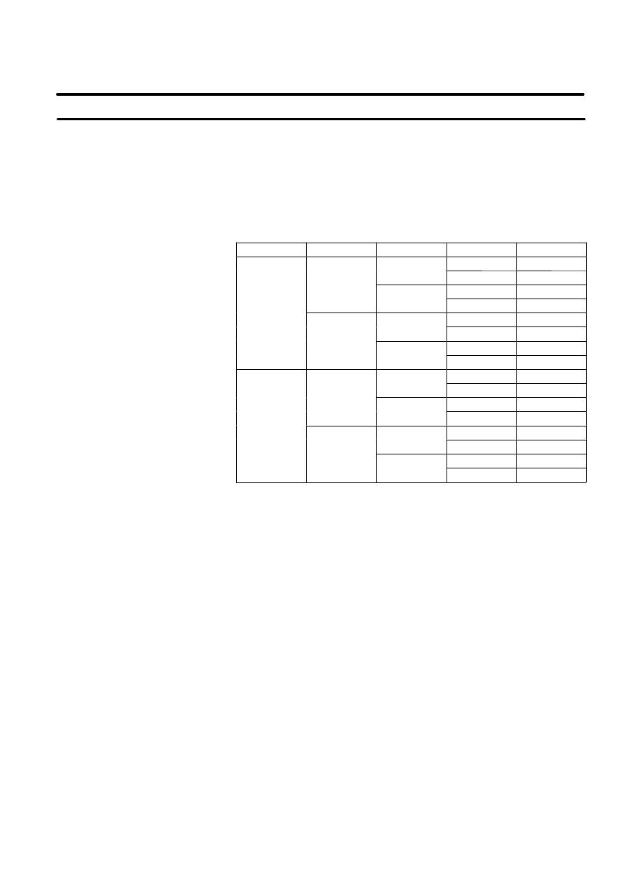
Table 2 lists the workings of outside the fence. In this table, the symbol
”o” means the working allowed to be carried out by the personnel.
Table 2. List of workings outside the fence
General
person
Operator /
Programmer
Maintenance
person
Power ON/OFF for Robot controller
o
o
o
Select operating mode (AUTO, T1, T2)
o
o
Select Remote/Local mode
o
o
Select robot program with teach pendant
o
o
Select robot program with external device
o
o
Start robot program with operator’s panel
o
o
o
Start robot program with teach pendant
o
o
Reset alarm with operator’s panel
o
o
Reset alarm with teach pendant
o
o
Set data on the teach pendant
o
o
Teaching with teach pendant
o
o
Emergency stop with operator’s panel
o
o
Emergency stop with teach pendant
o
o
Emergency stop with safety fence open
o
o
Maintain for operator’s panel
o
Maintain for teach pendant
o
5.3
WORKING PERSON

B--80687EN/03
7
5. FANUC ROBOT SYSTEM
In operating, programming and maintenance, the operator / programmer
and maintenance person take care of their safety using the following safety
protectors, for example.
D
Use adequate clothes, uniform, overall for operation
D
Put on the safety shoes
D
Use helmet
The programmer and maintenance person must be trained for the robot
operating and maintenance.
The required items are:
D
Safety,
D
Practice of jog feed,
D
Practical training of manual operation and teaching of robot,
D
Programming practice, teaching and playback practice,
D
Practice of automatic operation,
D
Explanation of configuration and function of robot,
D
Explanation and practice of setting up frame,
D
Explanation of outline of programming and program example,
D
Explanation of automatic operation,
D
Explanation of interface between robot and peripheral device,
D
Explanation and practice of check item when trouble occur,
D
Explanation of periodical inspection and exchange of consumable,
D
Explanation and practice of basic operation,
D
Explanation and practice of display for maintenance,
D
Explanation and practice of handling of floppy cassette,
D
Explanation and practice of initial setting,
D
Explanation and practice of controller,
D
Explanation and practice of checking item on trouble,
D
Explanation and practice of troubleshooting by error code,
D
Explanation and practice of servo system,
D
Explanation and practice of mastering, and
D
Explanation and practice of dis--assemble and assemble.
Some training courses for these items for the maintenance person or
system engineer are provided in the robot school and each technical service
center.
Please refer to Appendix B for contacts.
5.3.1
Robot Training

B--80687EN/03
8
5. FANUC ROBOT SYSTEM
A
CAUTION LABELS
9
B--80687EN/03
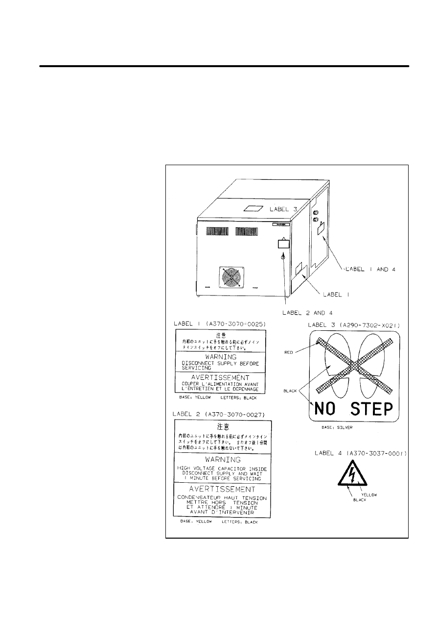
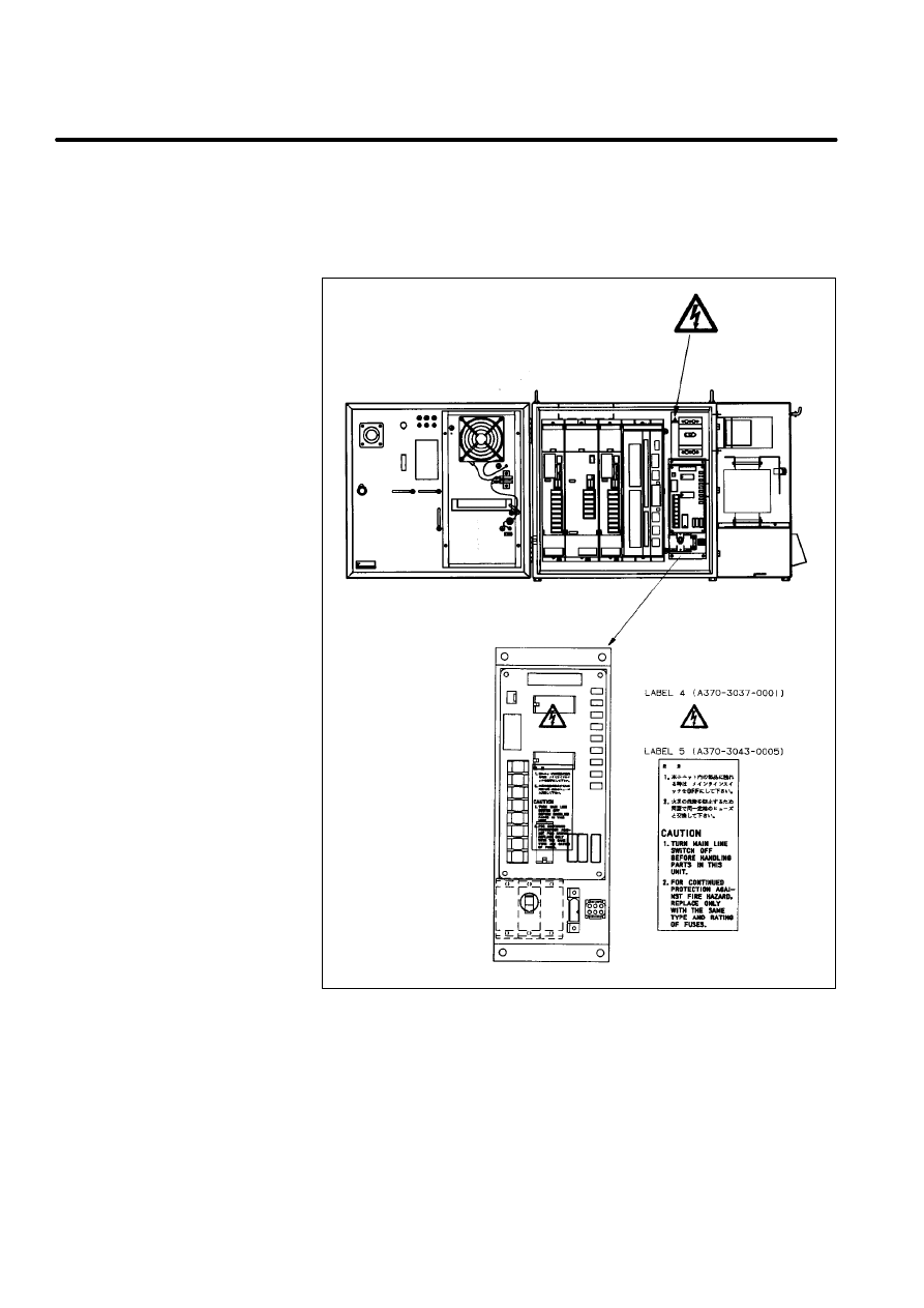
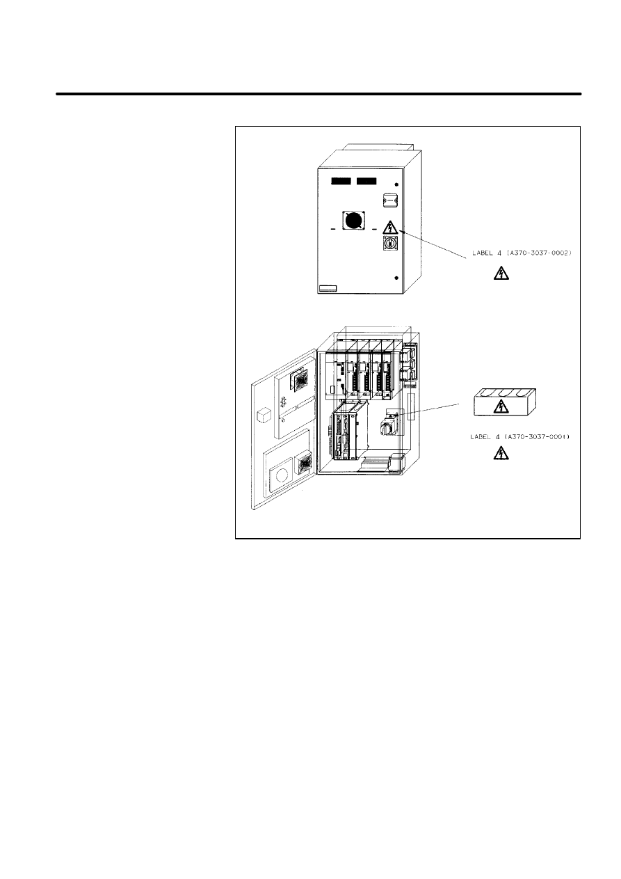
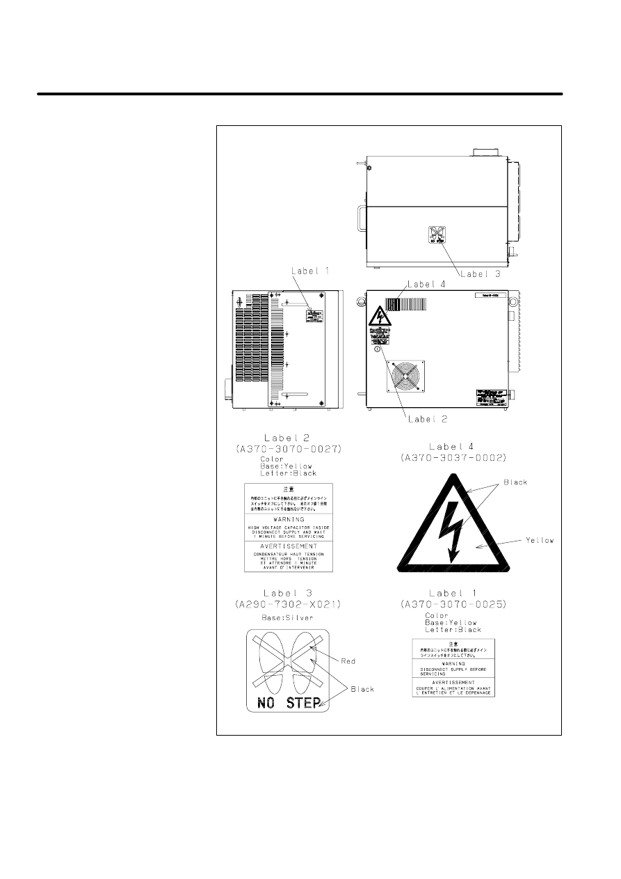
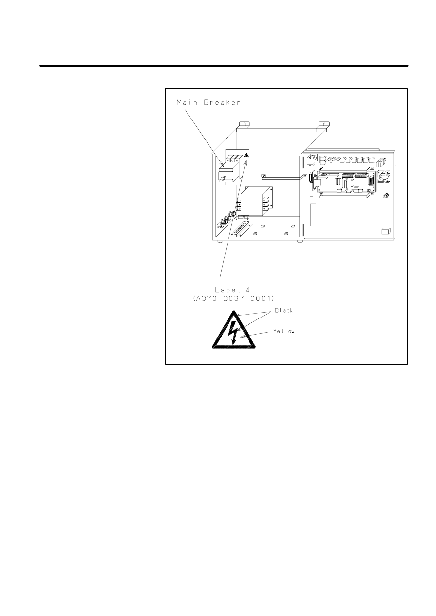
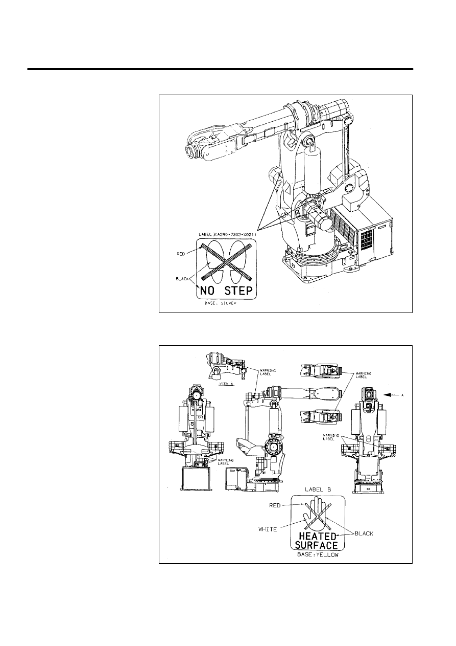
There are six kinds of caution labels fixed to the robot as follows.
D
Label 1: says ”WARNING, disconnect supply before servicing”.
D
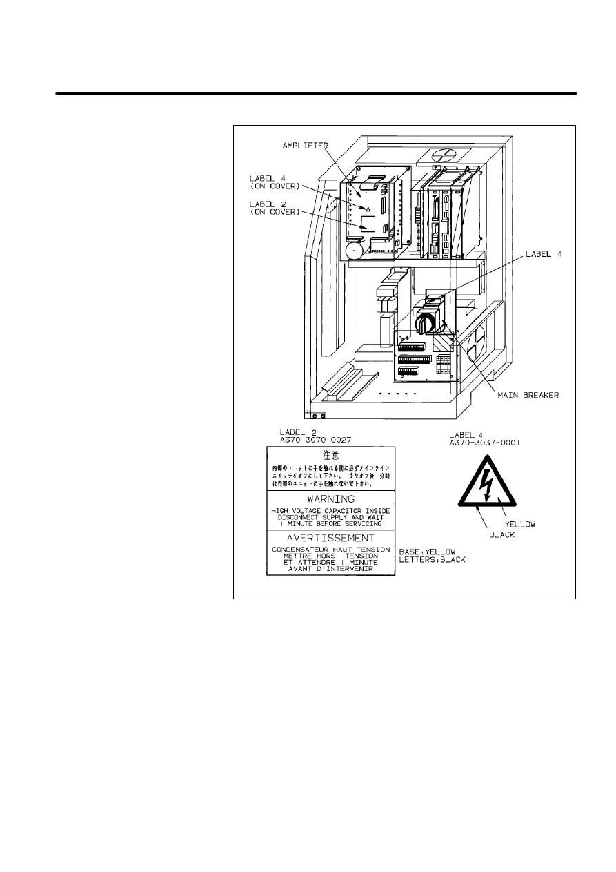
Label 2: says ”WARNING, high voltage capacitor inside disconnect
supply and wait 1 minute before servicing.
D
Label 3: says ”Don’t step on the robot”.
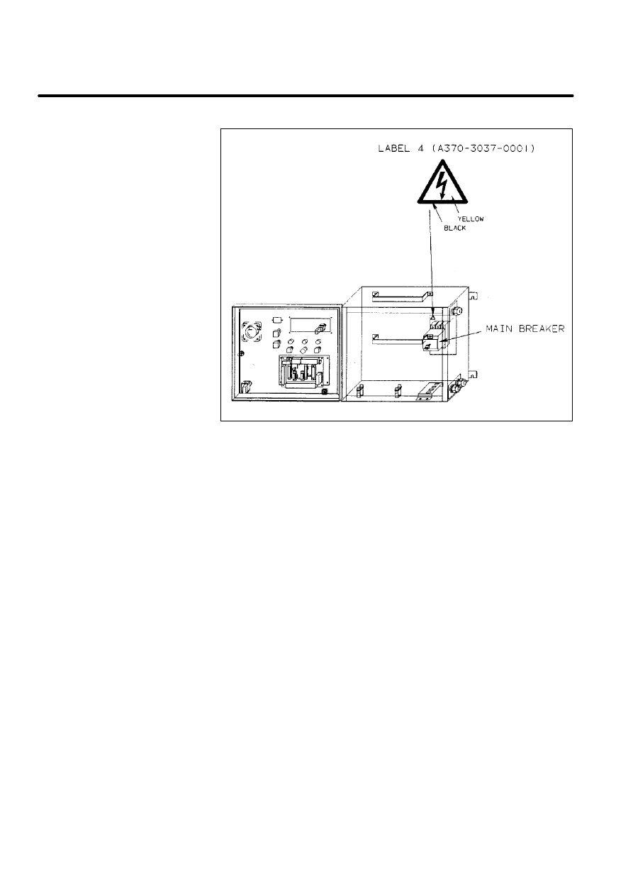
D
Label 4: says ”DANGER, connection of power supply”.
Caution label
(Controller)
[R--J2 i cabinet]
10
A. CAUTION LABELS
B--80687EN/03
Caution label
(Operator’s box)
[R--J2 i cabinet]
B--80687EN/03
11
A. CAUTION LABELS
Caution label
(Controller)
[R--J2 B cabinet]
12
A. CAUTION LABELS
B--80687EN/03
D
Label 5: says ”CAUTION,
1. Turn main line switch off before handling parts in this unit.
2. For continued protection against fire hazard. Replace only with the
same type and rating of fuses.
Caution label
(Controller)
[R--J2 Mate]
B--80687EN/03
13
A. CAUTION LABELS
Caution label
(Controller)
[R--J2 for M--410i]
14
A. CAUTION LABELS
B--80687EN/03
Caution label
(Controller)
[R--J3 i--cabinet]
B--80687EN/03
15
A. CAUTION LABELS
Caution label
(Operation box)
[R--J3 i--cabinet]
16
A. CAUTION LABELS
B--80687EN/03
D
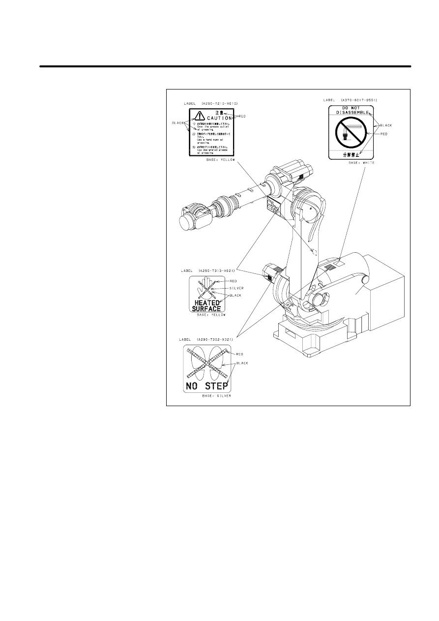
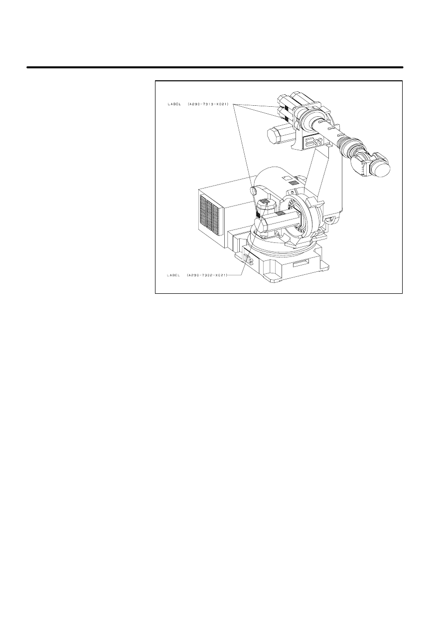
Label 6: says ”Don’t touch this heated surface”.
Caution label
(Mechanical unit)
[Example:S--420iF]
B--80687EN/03
17
A. CAUTION LABELS
8
7
6
3
Caution label
(Mechanical unit)
[Example:S--430iF]
18
A. CAUTION LABELS
B--80687EN/03
6
6
B
CONTACTS
19
B--80687EN/03
ADDRESS
PHONE
FANUC LTD
Oshino--mura, Yamanashi Prefecture
401--0597, Japan
TEL:81--555--84--5555
FAX:81--555--84--5512
FANUC Robotics N.A.
3900 West Hamlin Road,
Rechester Hills,
Michigan 48309--3253
Industrial
TEL:1--248--377--7582
FAX:1--248--377--7365
Automotive
TEL:1--248--377--7090
FAX:1--248--377--7365
Hot Line
(24hour service)
TEL:1--248--377--7159
FAX:1--248--377--7463
Training Department
TEL:1--248--377--7234
FAX:1--248--377--7367
FANUC Robotics West
15602 Mosher Avenue Tustin, California
92680
TEL:1--714--258--7075
FAX:1--714--258--7080
FANUC Robotics Central
2831 East Remper Road Cincinatti, Ohio
45241--4840
TEL:1--513--771--8844
FAX:1--513--771--5827
FANUC Robotics Ltd.
Canada
6395 Kestrel Road Mississauga, Ont. L5T
125 Canada
TEL:1--905--670--5755
FAX:1--905--670--4046
FANUC Robotics Mexico
Guadalupe I.Ramirez #715 Col. San Juan
Tepepan, Xochimilco Mexico D.F.
TEL:52--5--653--6506
FAX:same as above

20
B. CONTACTS
B--80687EN/03
PHONE
ADDRESS
FANUC Robotics Europe
S.A.
Zone Industrielle L--6468 Echternach,
Grand--Duche de Luxembourg
TEL:352--7277771
FAX:352--727777403
FANUC Robotics
Deutschland GmbH
Bernhauser Strasse 22, D--73765
Neuhausen, Germany
TEL:49--7158--187--250
FAX:49--7158--187--253
FANUC Robotics France
SARL
Z.I. du Bois--Chaland C.E. 2904--lisses
F--91029, Evry Cedex, France
TEL:33--1--69897000
FAX:33--1--69897001
FANUC Robotics UK Ltd.
Seven Stars Industrial Estate Wheler Road
GB--Coventry CV3 4LB, UK
TEL:44--203--639669
FAX:44--203--304333
FANUC Robotics Italia
s.r.l.
Vialle delle Industrie 12 I--20020
Arese(Mi), Italy
TEL:39--2--93581518
FAX:39--2--93581598
FANUC Robotics Iberica S.L.
Avda. de la Fama no.127 E--08940
Cornella, Spain
TEL:34--93--4743767
FAX:34--93--4744410
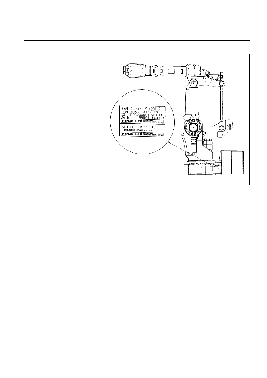
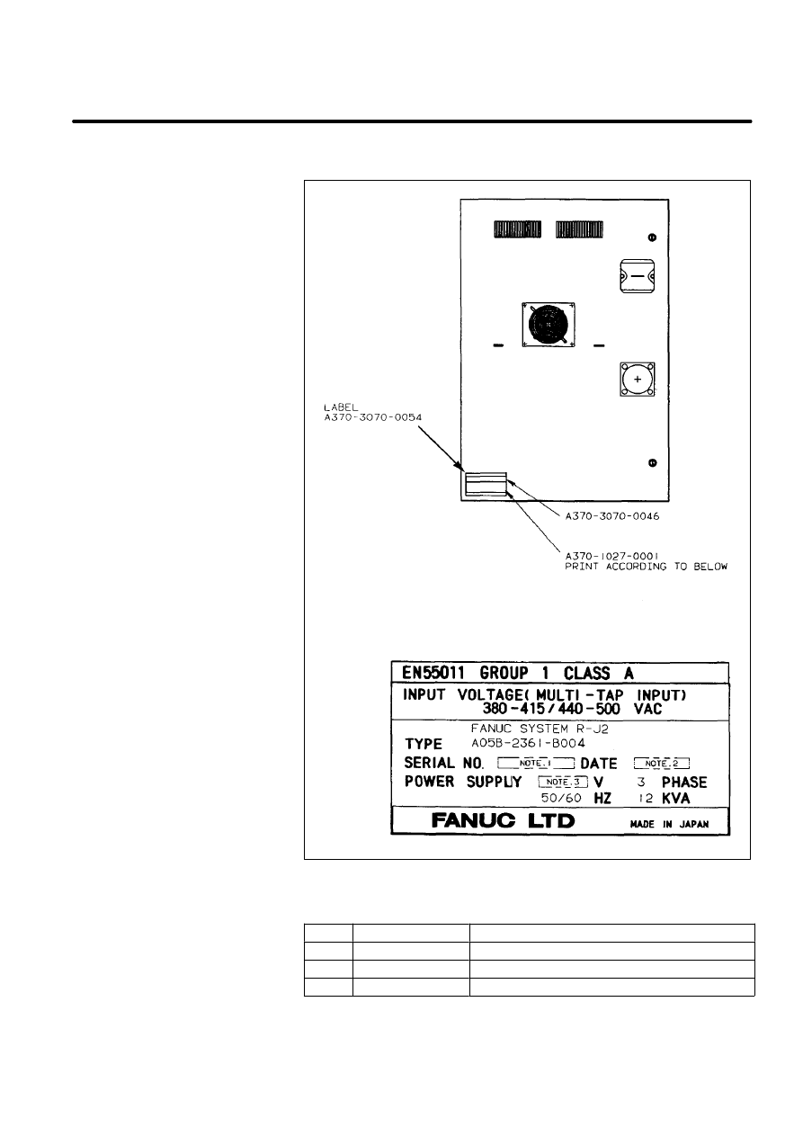
C
MANUFACTURER LABEL
21
B--80687EN/03
Manufacturer label
(Mechanical unit)
[Example:S--420iF]
22
C. MANUFACTURER LABEL
B--80687EN/03
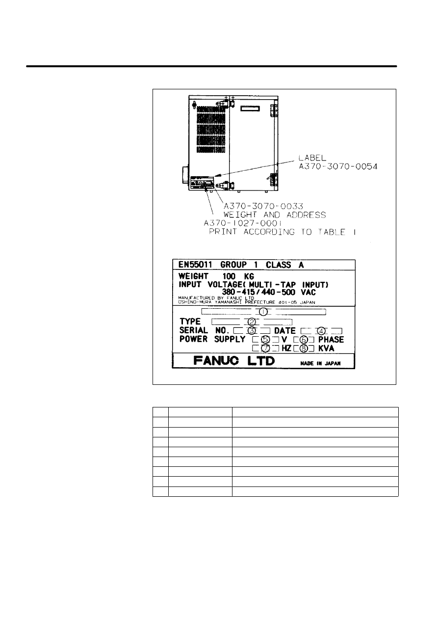
Table 1. Letters
No.
Contents
Letters
1
--
FANUC SYSTEM R--J2
2
TYPE
A05B--2350--B007
3
SERIAL NO.
Print serial No.
4
DATE
Print production year and month
5
V
Ordered voltage
6
PHASE
3
7
HZ
50/60
8
KVA
12
Manufacturer label
(R--J2 controller i cabinet)
[Example:For S--420iF
integrate type]
B--80687EN/03
23
C. MANUFACTURER LABEL
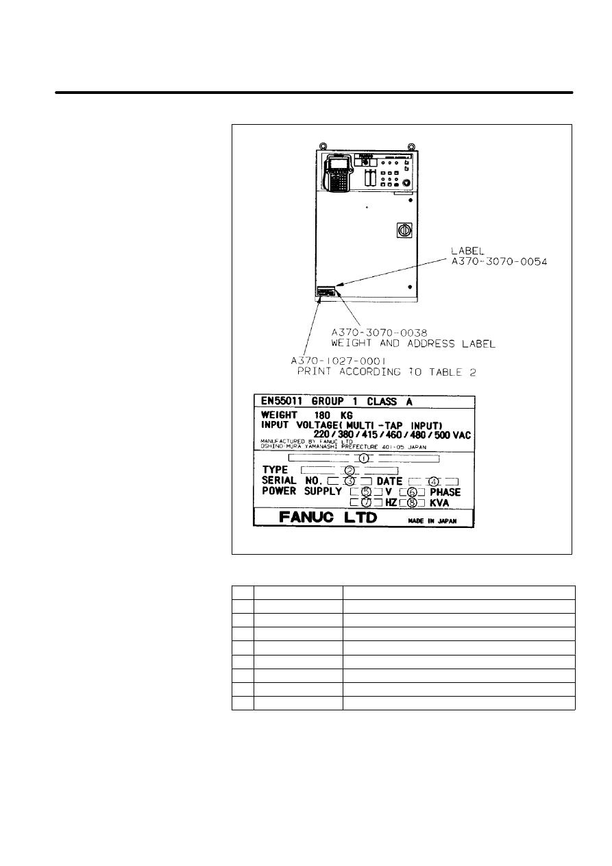
Table 2. Letters
No.
Contents
Letters
1
--
FANUC SYSTEM R--J2
2
TYPE
A05B--2351--B006
3
SERIAL NO.
Print serial No.
4
DATE
Print production year and month
5
V
Ordered voltage
6
PHASE
3
7
HZ
50/60
8
KVA
12
Manufacturer label
(R--J2 controller B cabinet)
[Example:For S--420iF]
24
C. MANUFACTURER LABEL
B--80687EN/03
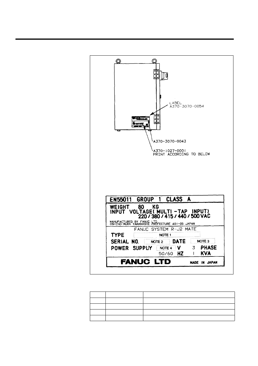
Table 3. Letters
Note
Contents
Letters
1
TYPE
A05B--2330--B012
2
SERIAL NO.
Print serial No.
3
DATE
Print production year and month
4
V
Ordered voltage
Manufacturer label
(R--J2 Mate controller)
[Example:
For LR Mate 100i]
B--80687EN/03
25
C. MANUFACTURER LABEL
Table 4. Letters
Note
Contents
Letters
1
SERIAL NO.
Print serial No.
2
DATE
Print production year and month
3
V
Ordered voltage
Manufacturer label
(Mechanical unit)
[Example:S--420iF]
26
C. MANUFACTURER LABEL
B--80687EN/03
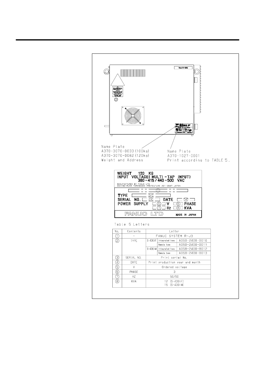
Manufacturer label
(R--J3 controller i cabinet)
[Example:for S--430i]
Revi
si
o
n
Reco
rd
FANUC
R
obot
S
A
FE
TY
HANDBO
O
K
(B
--80687E
N)
03
Aug.
,’
98
Addi
tion
of
R-
-J
3
i--
cabi
net
.
02
Jul
.,
’96
Addi
tional
descr
ip
tions
of
B-
-c
abi
net
.
01
Feb.
,’
95
E
ditio
n
Dat
e
Cont
ent
s
E
ditio
n
Dat
e
Cont
ent
s

Index
B--80687EN/03
i--1
≪A≫
After automatic operation, 33
Automatic operation, 30
≪B≫
Before powering on, 33
≪C≫
Commissioning and functional testing, 27
Configuration of robot system, 5
Control unit, 34
≪D≫
Daily maintenance, 33
Deadman switch, 20
Designation of the restricted space, 27
During programming, 29
≪E≫
Emergency stop, 17
End effector, workpiece and peripheral equipment, 14
≪F≫
FANUC robot system, 3
≪G≫
General cautions, 27
General precautions, 1
≪I≫
Installation, 27
≪M≫
Maintenance, 31
Mechanical unit, 33
Mode select switch, 17
≪O≫
Operating modes, 20
Other cautions, 32
Other precautions, 11
Other protection devices, 22
≪P≫
Placement of equipment, 9
Power supply and protective earth connection, 11
Prior to programming, 29
Program verification, 30
Programming, 29
Purpose of robot, 3
≪R≫
Restriction of personnel, 28
Returning to automatic operation, 29
Robot stop variation, 25
Robot system design, 9
Robot system restart procedures, 28
Robot training, 7
≪S≫
Safeguards, 21
Safety and operational verification, 28
Safety devices, 17
Safety fence, 21
Safety gate and plugs, 21
Saving programmed data, 30
≪T≫
The safety sequence for fence entry, 23
Trouble shooting, 30
≪W≫
Working person, 6

July., 1996
FANUC LTD
Printed in Japan
Document Outline
- SAFETY HANDBOOK
- Table of Contents
- 1 GENERAL CAUTIONS
- 2 ROBOT SYSTEM DESIGN
- 3 SAFETY DEVICES
- 4 DAILY MAINTENANCE
- 5 FANUC ROBOT SYSTEM
- A CAUTION LABELS
- B CONTACTS
- C MANUFACTURER LABEL
- Index
Wyszukiwarka
Podobne podstrony:
Safety Handbook [B 80687EN 09]
03 E83 Safety Systems
03 safety chain solution Safe Stop0
03 Aramaic (Beyond Babel A Handbook of Biblical Hebrew and Related Languages)
03 Sejsmika04 plytkieid 4624 ppt
03 Odświeżanie pamięci DRAMid 4244 ppt
podrecznik 2 18 03 05
od Elwiry, prawo gospodarcze 03
Probl inter i kard 06'03
TT Sem III 14 03
03 skąd Państwo ma pieniądze podatki zus nfzid 4477 ppt
03 PODSTAWY GENETYKI
Wyklad 2 TM 07 03 09
03 RYTMY BIOLOGICZNE CZŁOWIEKAid 4197 ppt
więcej podobnych podstron