
Initial Print Date: 12/04
Table of Contents
Subject
Page
Base Cluster Overview IPO (as introduced to 9/98) . . . . . . . . . . . . . . . .10
Redundant Data Storage . . . . . . . . . . . . . . . . . . . . . . . . . . . . . . . . . . . . . . .11
On Board Computer (Base Cluster) . . . . . . . . . . . . . . . . . . . . . . . . . . . . . .12
Base BC/Instrument Cluster Test Functions . . . . . . . . . . . . . . . . . . . . . .13
Base Instrument Cluster
Revision Date:

2
Base Instrument Cluster
Base Instrument Cluster (Kombi)
Model: E39 and E53 with base cluster
Production: Start of Production
After completion of this module you will be able to:
• Compare the base instrument cluster with the IKE
• Understand the functions of the base instrument cluster
• Diagnose concerns with the base instrument cluster
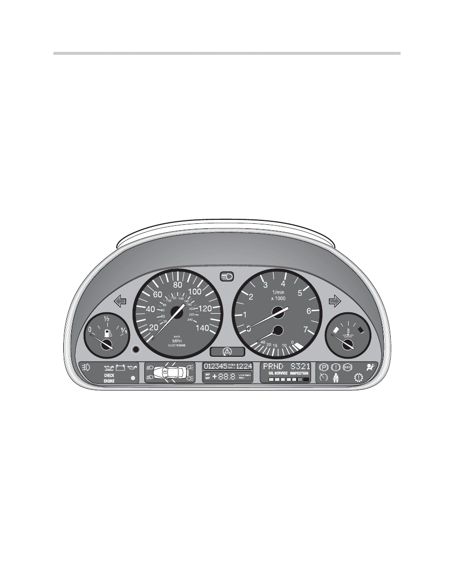
Base Instrument Cluster
The base instrument cluster differs from the high version cluster by lack of the IKE. All
processing is performed internally in the cluster. Also, there is no Check Control display
matrix, but rather a check control pictogram.
The cluster consists of five analog gauges. The processing electronics and drivers for the
gauges are contained in the cluster. The five gauges include:
• Fuel Gauge
• Speedometer
• Tachometer
• Fuel Economy Gauge
• Coolant Temperature
Three Liquid Crystal Display blocks are provided for the:
• Check Control Display - pictogram
• Mileage, Outside Temperature and BC Display
• Transmission Range and SI Display
Warning lamps and indicators are positioned to the left and right of the display blocks.
The number of warning lamps is greater on the base cluster for the display of several
check control warnings. All of the warning lamps and indicators are LEDs and not
replaceable.
Critical warning lamps use two LEDs for a safety margin.
There are replaceable lamps for the back lighting on the liquid crystal display units.
3
Base Instrument Cluster
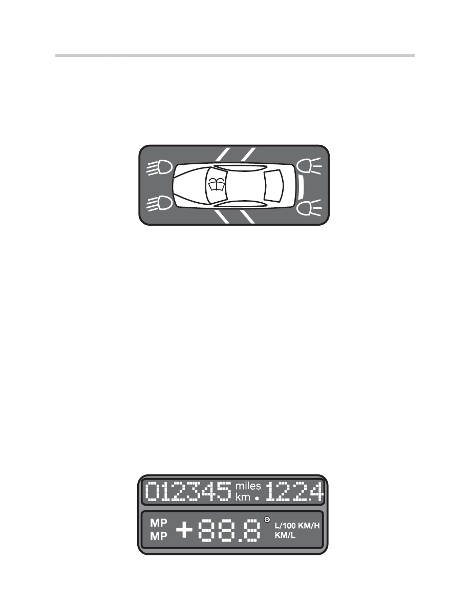
The
Left Display Block contains a pictogram for various check control warnings. LED’s
within the display will illuminate for:
• Lighting failures for headlight (low beam),taillight and brake lights.
• Open doors or trunk
• Low washer fluid
Additional circuits monitored by check control include the oil level and transmission
emergency program. These warnings are indicated by lamps positioned in both indicator
display areas on the left and right sides on the bottom of the instrument cluster.
Due to the ability to illuminate multiple warning LEDs, there is no priority displays for the
pictogram check control. If multiple faults exist, each corresponding LED will illuminate.
The LED will remain illuminated as long as the fault exists. The only exception is the
washer fluid which will go out 60 seconds after KL 15 is switched ON.
All check control and lamp control circuits are monitored by the Light Check Module
(LCM). When failures or faults exist, the messages are passed to the cluster for display
over the K-Bus.
The
Middle Block contains the displays for the Total Mileage, Trip Mileage and Board
Computer.
The total mileage is stored in non-volatile memories in the cluster EEPROM and the
LCM.
The mileage can be displayed with the key off for 25 seconds if the mileage reset button
is pressed.
Board Computer information can be displayed by pressing the turn signal lever.
NOTE: The outside temperature is displayed automatically every time the
key is switched ON.
4
Base Instrument Cluster
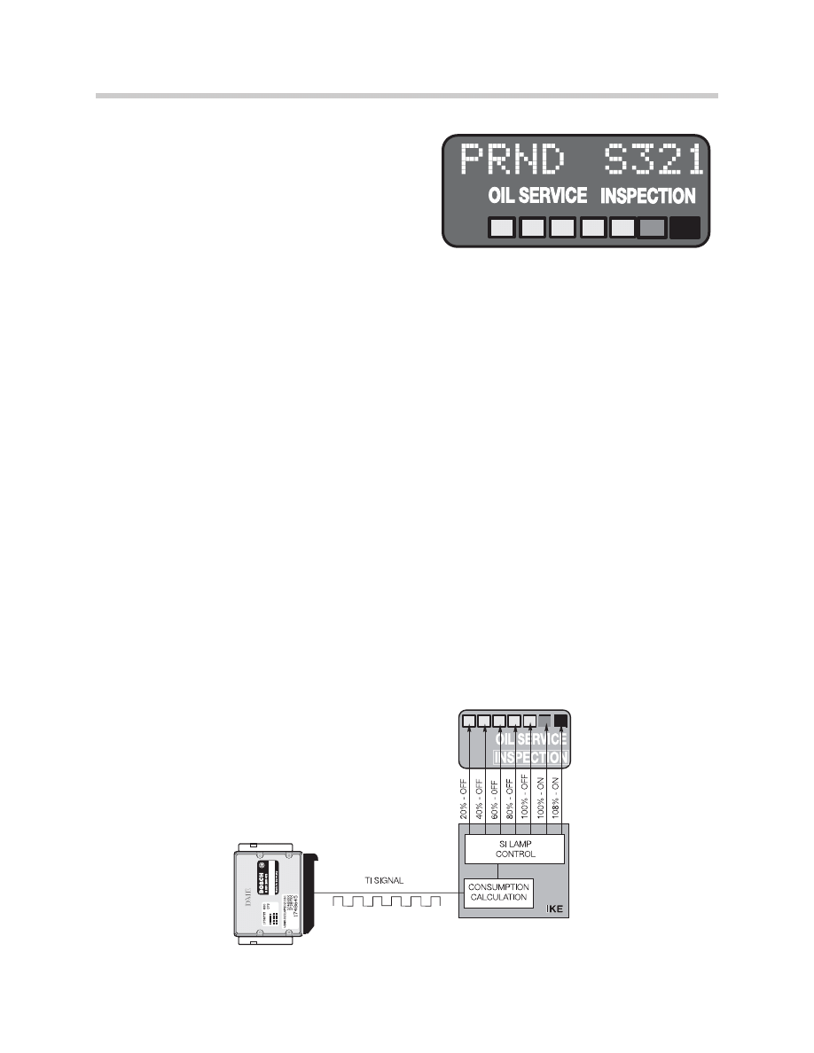
The
Right Block contains the displays for
the automatic transmission driving range and
the Service Interval Indicator III.
The display of the Service Indicator on the
E39 is the same as previous systems. The
processor for the intervals is located in the
cluster electronics. However, the processing
method for determining interval times has
changed. The E39 uses the new Service Interval III system. Interval times are based on
fuel consumption instead of mileage and starts. This system was introduced on the
1996 E38 750iL was subsequently phased into the other models.
Using fuel consumption offers several advantages over the previous method for determin-
ing oil service.
• First, the processing electronics are less involved in that only one value is needed for
the processing.
• Second, the use of fuel consumption is a more accurate method of determining
engine load and the need for service.
• Third, resetting of the indicator before the scheduled time will not effect the time to
the next service.
A set volume of fuel (in liters) is stored in the EEPROM of the SI. The volume of fuel is
dependent on the vehicle and engine size. The processor receives the “ti” signal as the
vehicle is used. As 20% of the stored volume is consumed, one of the green LEDs will
go out. Each successive 20% of fuel consumption will cause the next LED to go out
until 100% of the stored volume has been consumed. At this point the yellow LED will
come on indicating the service is due. At 108% of the volume, the RED LED will
illuminate indicating an over due service.
With every reset, the total volume of fuel is restored in the EEPROM and the calculation
starts over again.
5
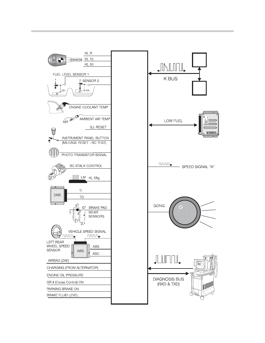
Base Instrument Cluster
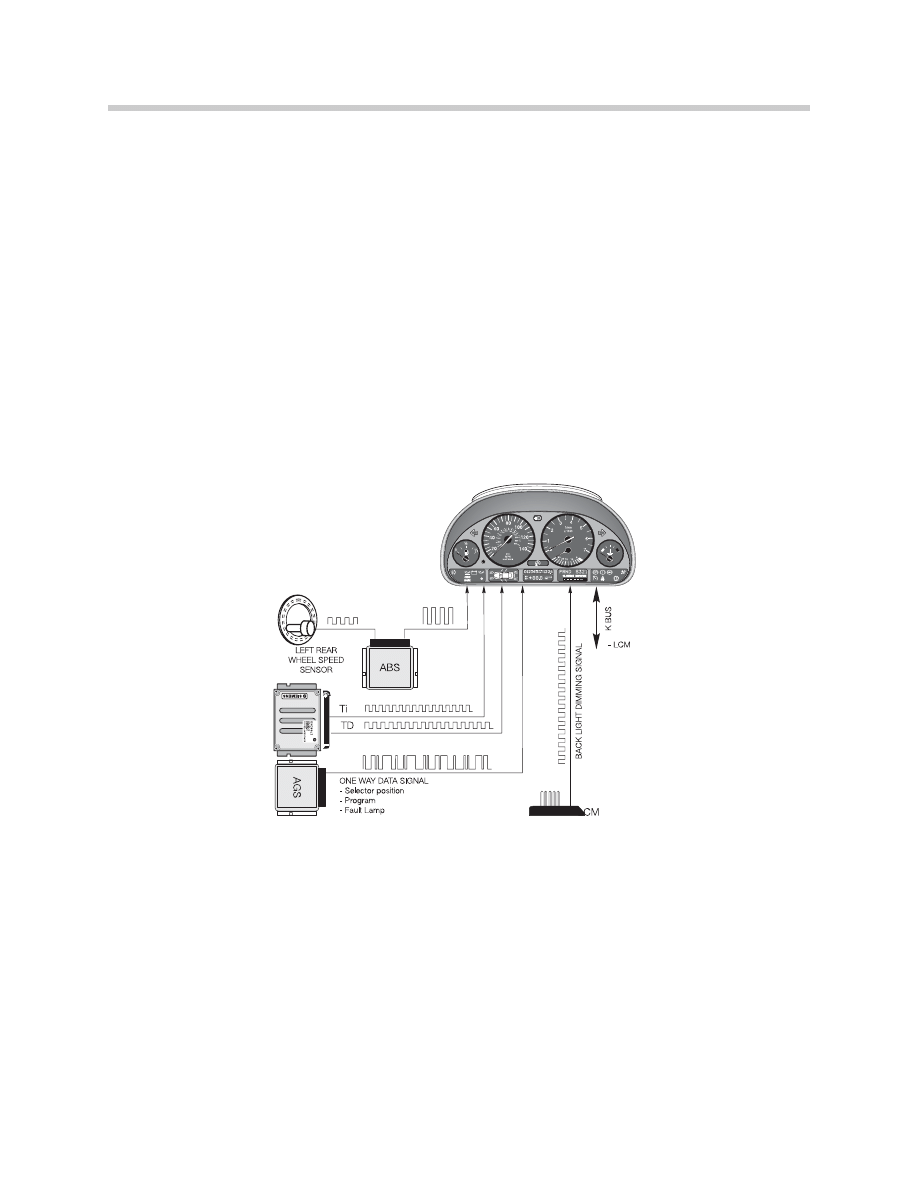
Dynamic Digital Inputs
Distance Signal
This input is supplied to the cluster by the ABS/ASC+T (or DSC) control module as a
square wave signal. Pulses from the left rear wheel speed sensor are processed by the
ASC/DSC module to produce this signal. The cluster electronics process the input for
the cluster display and pass the signal along, on the K-Bus, as speed signal “A” for other
control modules requiring the vehicle speed signal.
Engine Control Module Signals
The “Ti” & “TD” signals are produced by the engine control module (DME) and sent to
the cluster. On models produced before 9/98, the “Ti” and “TD” signals were sent to the
cluster via a dedicated signal line.
From 9/98, these signals are sent to the cluster via the CAN-Bus.
The cluster processes the signals for the tachometer and fuel economy indicator displays.
The Ti signal is used by the cluster for the SI indicator. The cluster also passes the TD
signal out over the K Bus.
Transmission One Way Data Signal
The transmission control module (EGS/AGS), provides a one way data signal to the
instrument cluster for signalling of the range selector position, driving program and for
fault lamp activation.
From 9/98, the transmission information is sent to the cluster via the CAN-Bus.
Dimmer Signal
This is a pulse-width modulated signal from the LCM. It is used to control the intensity of
the back lighting of the instruments and the LCDs when the lights are switched ON. This
signal is also output over the “K” Bus.
K-Bus Signalling
The Cluster receives signals for the Check Control Pictogram over the K-Bus.
6
Base Instrument Cluster
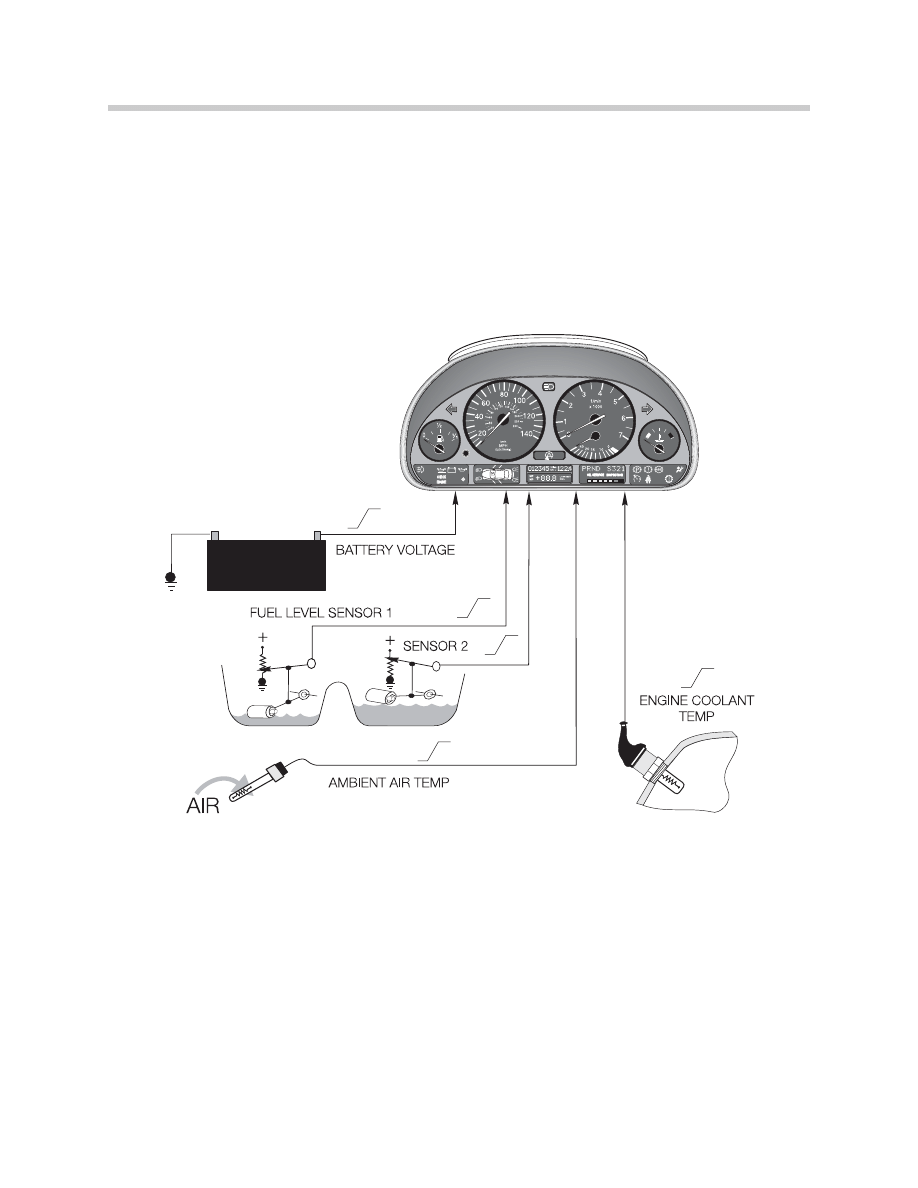
Analog Input Signals
Battery Voltage
Battery voltage is monitored by the cluster and a fault is stored if the voltage exceeds
16 volts
Fuel Tank Level
Two lever action sensors are wired in parallel to the cluster. The two varying voltage
signals are processed by the cluster for fuel gauge and low fuel warning display.
Coolant Temperature
A NTC sensor is used to measure coolant temperature the cluster uses this input for
temperature gauge display. The NTC sensor is a dual NTC, one of the NTC circuits is an
input to DME, the other NTC is an input to the cluster.
From 9/98, the coolant temperature sensor in an input to the DME only, the cluster
receives the temperature information via the CAN-Bus. The dual NTC is eliminated.
Outside Temperature Sensor
A NTC sensor is used to measure the ambient temperature. The signal is processed by
the cluster and passed out over the K Bus to modules requiring this input for processing.
7
Base Instrument Cluster
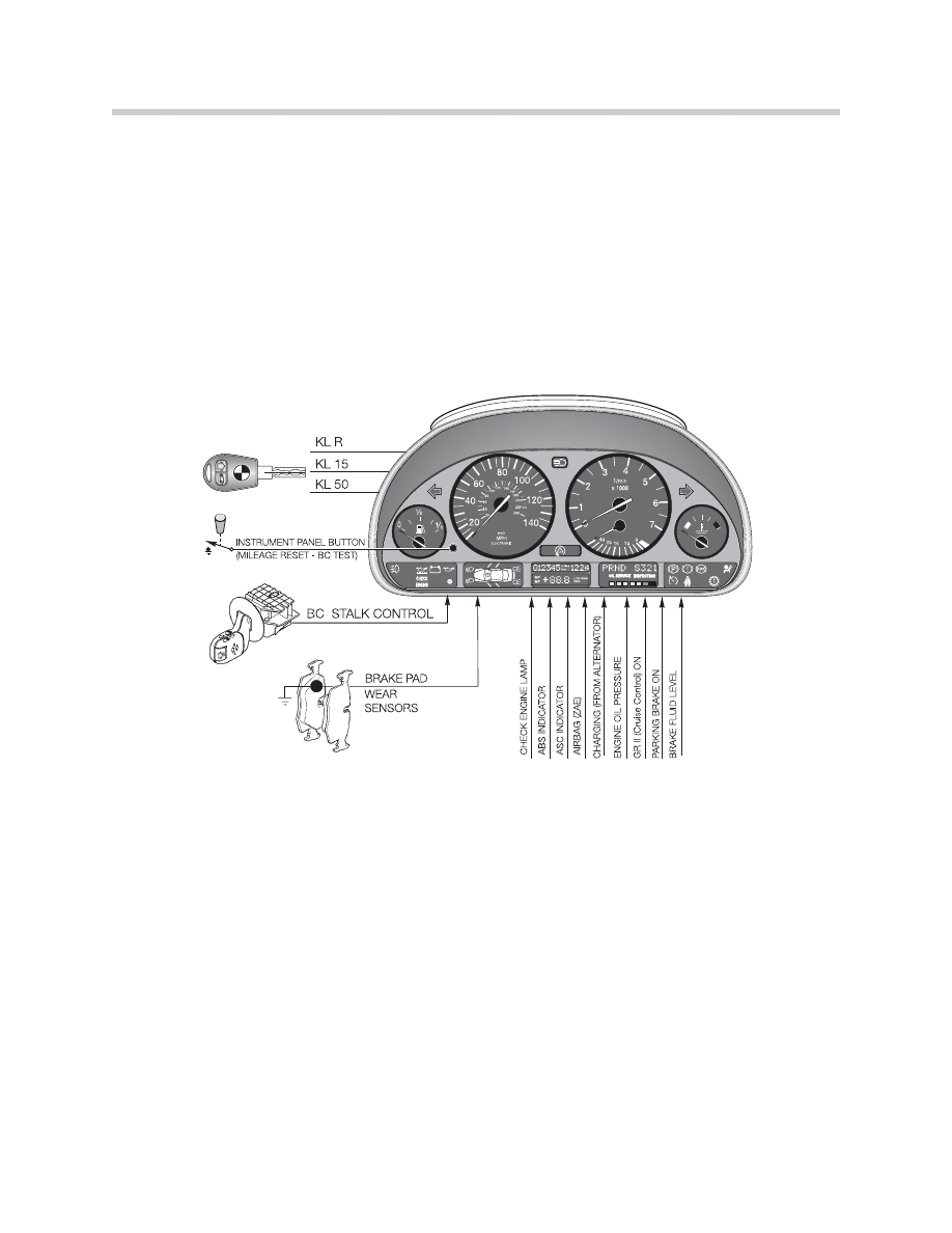
Digital Input Signals
The normal ignition switch terminals (KL R, KL 15 & KL 50) are input to the cluster.
Various functions are dependent on ignition switch position.
Steering Column Switch (LSS)
As with previous systems the turn signal stalk is used to call up BC functions. The LSS is
also referred to as the BC stalk control switch. It provides a ground input to the cluster.
Brake Pad Wear Sensors
The pad sensor inputs are used to illuminate the brake pad warning indicator as in the
past.
Instrument Panel Button
The reset button is used to reset the trip odometer as in the past. It will also display the
mileage, if pressed with the key switched OFF. This button is also used for the Base
BC/instrument cluster test functions.
Inputs for Warning Lamps
Various switches are used to signal the cluster for warning and indicator lamp illumination
including:
• Engine Oil Pressure
• Check Engine Lamp (MIL) from the ECM (DME)
• ASC/DSC/ABS warning lamps
• Parking Brake indicator
Some of these inputs are now provided via bus systems such as the CAN or K-Bus.
8
Base Instrument Cluster
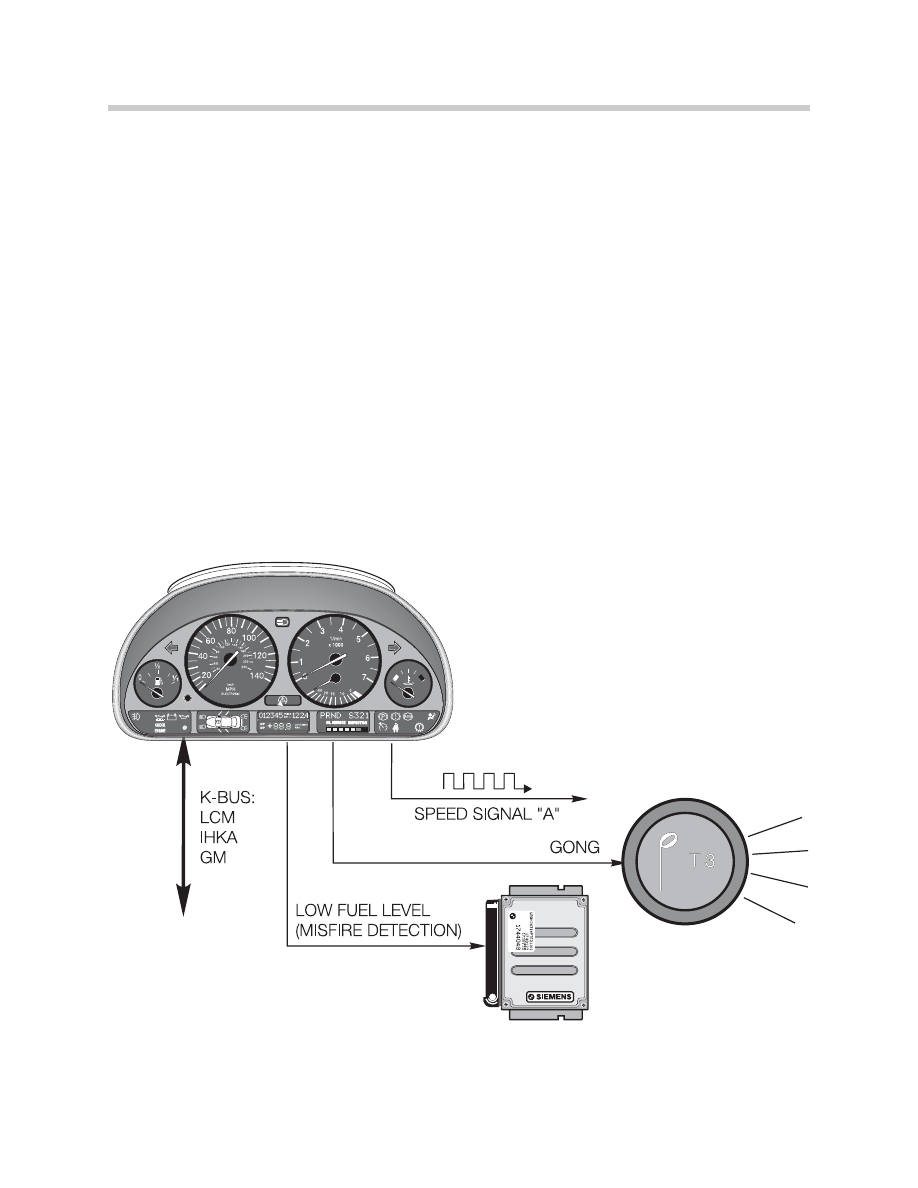
Output Signals
Speed Signal “A”
The vehicle speed signal is available as an output for control modules that require precise
vehicle speed information.
“K” Bus Interface
The K Bus is used to transfer data between the cluster and other modules on the link.
The diagnostic interface also passes over the K Bus for troubleshooting with the
DISplus/GT-1.
Low Fuel
Based on the processing for the low fuel indicator lamp, this output is also sent to the
engine control module (ECM). The signal is stored along with a misfire detection fault for
troubleshooting purposes.
Gong Output
T3, The T3 tone is used for check control warnings.
9
Base Instrument Cluster
Base Cluster Overview IPO (as introduced to 9/98)
10
Base Instrument Cluster
Base Cluster
as introduced
(E39)
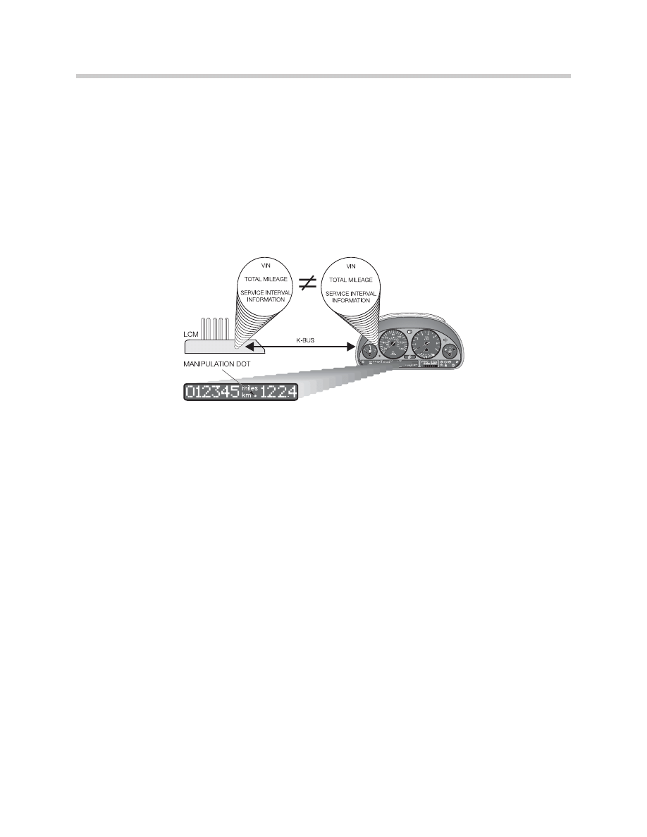
Redundant Data Storage
The specific information stored redundantly includes:
• Vehicle ID number
• Total mileage
• Service Interval data
The data is stored in the cluster and in the Light Check Module (LCM). The storage of
this data follows the redundant storage of the E38. It prevents the loss of total mileage or
SI data in the event of a cluster processor failure.
The data is compared each time KL 15 is switched ON. If the data does not match, the
manipulation DOT in the mileage display is illuminated.
Because of this redundant storage feature, the following points must be noted:
1. If the vehicle ID number is not the same in both modules, the manipulation DOT is
illuminated and no data transfer takes place. All functions of both modules will
continue to operate.
2. Data will only be accepted by the cluster from the LCM if the ID numbers match and
the cluster mileage is zero.
3. The vehicle ID number is input into the cluster through coding and will only be
accepted when the cluster is at zero mileage.
4. The LCM stored mileage can only be overwritten with a higher mileage and is
updated every 60 miles.
5. If the mileage differs by more than 120, and the ID numbers are the same, the
cluster will continue recording the mileage and set a fault for data transfer.
6. If the K Bus link to the LCM fails, the cluster will continue to record mileage and store
a fault for the data link.
These conditions will only allow new components to be installed for replacement
purposes. However, a used component can be installed for testing purposes. If a cluster
from another vehicle is used for testing purposes, road testing of the vehicle should be
avoided, because the cluster will accumulate mileage.
11
Base Instrument Cluster

On Board Computer (Base Cluster)
The On Board computer information on the base variant cluster can only be displayed in
the center matrix. The following information can be displayed:
On vehicles up to the 98 model year, when KL R is switched ON, the outside tempera-
ture will be displayed. To call up any other function, the turn signal lever must be pressed
and released. The other functions are than displayed one after the other. A blank field is
provided after the average speed display to allow the driver to switch off the display.
On vehicle from 98, the display which was last called up will be retained when KLR is
switched back on.
A freeze warning is incorporated in the BC. If the temperature drops below 37OF, the
gong will sound and the temperature display will flash in the BC. Pressing the turn signal
lever will cancel the display.
Two of the displays “Average Fuel Consumption” and “Average Speed” can be reset to
start new calculations. To reset the displays, press and hold the turn signal lever, for
longer than one second, when the function is called up. The BC will than start to com-
pute a new average value.
12
Base Instrument Cluster
Base BC/Instrument Cluster Test Functions
In addition to the fault memory and diagnostic link, the base instrument cluster contains a
series of test functions that can be accessed to check various functions and values. The
test functions are displayed in the mileage LCD block. There are a total of 21 test
functions.
The test functions are similar to those of previous Board computers and contain similar
tests.
• Tests 1 & 2 are always unlocked.
• Tests 3 -21 are only accessible after unlocking the test function. Test 19 is the
unlock function for accessing the displays.
13
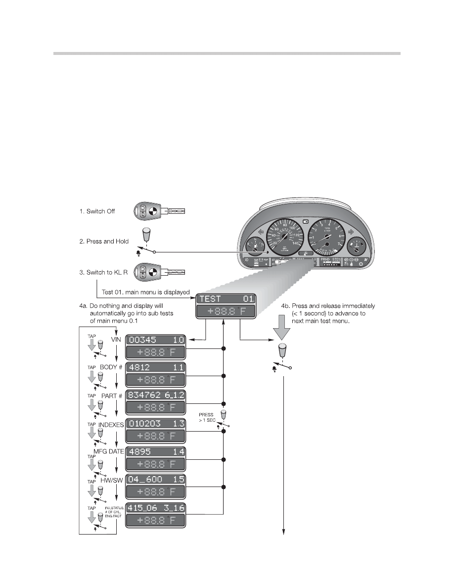
Base Instrument Cluster
Scrolling through the
numbered test functions is
achieved by pressing the
instrument cluster button
when the number is displayed.
The button is either pressed
momentarily (tapped) < 1
second or pressed and held
for > 1 second.
This signals the BC to display
the sub-tests of the displayed
main test menu or continue on
to the next main test menu.

Test No. 1
Vehicle specific data including:
Sub-Tests:
12345 1.0
= VIN
4812 1.1
= Body number
834762 6_1.2 = Part number of cluster
010203 1.3
= Coding/Diagnosis/Bus index
3495 1.4
= Manufacturing date (calendar week/year)
04_600 1.5
= Hardware/software # of cluster (HW:04, SW:6.00)
415_06 3_1.6 = Injection status, number of cylinders, engine factor
Test No. 2
Cluster System Test - activates the gauge drivers, indicators and LEDs to confirm
function.
Test No. 3
SI data
Sub Tests:
1500 3.0 = Liters
0 3.1 = Periodic inspection days (not applicable for US).
Test No. 4
Momentary Consumption
Sub Tests:
0267 4.0 = 26.7 liters/1000km
0073 4.1 = 7.3 liters per hour
Test No. 5
Distance Gone Consumption
Sub Tests:
0195 5.0 = 19.5 liters/100 km
226 5.1 = momentary distance to go (226km)
14
Base Instrument Cluster

Test No. 6
Fuel level sensor inputs in liters
Sub Tests:
237415 6.0 = Fuel level averaged
• LH sensor input = 23.7 liters
• RH sensor Input = 41.5 liters
0652 6.1 = Total tank level averaged = 65.2 liters
0667 1_6.2 = Indicated value and tank phase
• 1 = both sensors OK
• 2 = one sensor fault
• 3 = implausible input
Test No. 7
Temperature and Speed
Sub Tests:
032 7.0 = Coolant temp input 32OC
245 7.1 = Outside temp input 24.5OC
5283 7.2 = Engine speed 5,283 RPM
058 7.3 = Vehicle speed 58km/H
Test No. 8
Input values in HEX form
Sub Tests:
XXX 8.0 - 8.3 = Hex code, Instrument cluster inputs
Test No. 9
Battery voltage
Sub Test:
125 9.0 = 12.5 volts
Test No. 10
Country Coding
Sub Test:
02 10.0 = US 02
15
Base Instrument Cluster
Test No. 11
Cluster code
Sub Test:
000003 11.0 = Cluster code
Test No. 12
Not used
Test No. 13
GONG test
Sub Test:
Gong 13.0 = Activate gong by pressing button (gong response is delayed).
Test No. 14
Fault memory (not for diagnosis)
Test No. 15-18
Not used
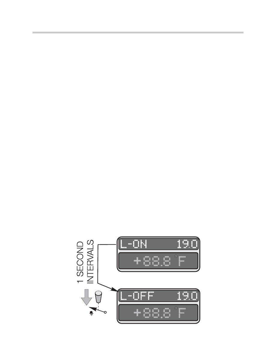
Test No. 19
LOCK/UNLOCK
Sub-Tests
L-ON...
L-OFF 19.0 =
Display changes from “L-ON” to “L-OFF” every second. To unlock test functions, press
the cluster button immediately when it changes to “L-OFF”. Tests are automatically
locked when exiting test functions.
16
Base Instrument Cluster

Test No. 20
Average fuel consumption - correction factor
The factor follows previous systems, with adjustment range of 750 to 1250. The adjust-
ment method is new for the base cluster. If adjustment is necessary, enter into test 20
using the cluster button. The correction factor number is changed by using the sub-tests
for the “ones, tenths and hundreds of the factor number. The digits will automatically
scroll through 0-9 within each group (ones, tenths, hundreds).
Sub-Tests:
XXX9 20.0 = Press the button when the correct “ones” position is attained.
XX5X 20.1 = Press the button when the correct “tenths” position is attained.
12XX 20.2 = Press the button when the correct “hundreds” position is attained.
Test No. 21
Software reset
Sub-Test:
reset 21.0 = Reset software
17
Base Instrument Cluster

Workshop Exercise
Using an instructor designated vehicle, enter the instrument cluster test functions
using the proper procedure. Access all test steps and complete worksheet.
Explain the proper procedure to unlock the instrument cluster:
Perform Test 02
How is this test useful in diagnosis?
Perform Test 20
How is this test useful in diagnosis?
How is Test Step 21 useful in diagnosis?
18
Base Instrument Cluster

Workshop Exercise
Using an instructor designated vehicle, connector the appropriate test cables to the
instrument cluster. Access the correct ETM and complete worksheet below.
What is the KL30H signal used for?
Using the oscilloscope measure the KL58g signal. Record observations below.
Operate the dimmer switch from low to high and observe oscilloscope.
What are the readings obtained from the KL58g signal?
Monitor CAN-Bus using oscilloscope and record observations below?
Disconnect CAN-Bus from instrument cluster and observe (faults/functions etc.)
What was observed on the cluster with the CAN-Bus disconnected?
Disconnect the ambient temperature sensor input to the instrument cluster (or
unplug sensor).
What happens to the temperature display? What other system are affected?
19
Base Instrument Cluster

Classroom Exercise - Review Questions
1.
What vehicles use the base instrument cluster?
2.
How are lamp failures and low fluid levels displayed on the base instrument
cluster?
3.
What is displayed in the “middle display block” on the base cluster?
4.
Explain SIA III processing as compared to SIA II?
5.
How can the instrument cluster test functions be used to diagnose fuel gauge
complaints?
20
Base Instrument Cluster

Classroom Exercise - Review Questions
6.
What is the difference between coolant temperature input in vehicles before and
after 9/98 production?
7.
What is the “low fuel” output signal used for?
8.
What information is stored redundantly between the cluster and LCM?
9.
Why should the cluster and LCM not be replaced simultaneously?
10.
What instrument cluster test functions are always unlocked?
21
Base Instrument Cluster
Document Outline
- Main Menu
- Introduction to Bus Systems
- Power Supply and Bus Systems
- Instrument Cluster Electronics
- Base Instrument Cluster
- Lighting Systems
- Entertainment and Communication
- Vehicle Features
- Navigation Systems
- Central Body Electronics ZKE III
- E46 Power Supply and Bus Systems
- E46 Driver Information Systems
- E46 Lighting Systems
- E46 Entertainment Systems
- E46 Central Body Electronics
- E85 Power Supply and Bus Systems
- E85 Driver Information
- E85 Central Body Electronics
- E85 Info and Communication Systems
- E83 Electronic Systems
- Glossary
Wyszukiwarka
Podobne podstrony:
instrument cluster
BMW Instrument Cluster Language
Instrument Cluster Circuit (1 of 2)
BMW E38 schematic Instrument cluster
Kody błędów Jaguar X Type instrument cluster issues
Instrument Cluster Circuit (2 of 2)
wykład 6 instrukcje i informacje zwrotne
Instrumenty rynku kapitałowego VIII
05 Instrukcje warunkoweid 5533 ppt
Instrukcja Konwojowa
2 Instrumenty marketingu mix
Promocja jako instrument marketingowy 1
Promocja jako instrument marketingowy
więcej podobnych podstron