
Volkswagen/Audi
Vehicle Communication
Software Manual
February 2013
EAZ0031B01D Rev. B

ii
Trademarks
Snap-on is a trademark of Snap-on Incorporated.
All other marks are trademarks or registered trademarks of their respective holders.
Copyright Information
©2013 Snap-on Incorporated. All rights reserved.
Disclaimer
The information, specifications and illustrations in this manual are based on the latest information available at the
time of printing.
Snap-on reserves the right to make changes at any time without notice.
Visit our website at:
http://diagnostics.snapon.com (North America)
For Technical Assistance
CALL 1-800-424-7226 (North America)

iii
Safety Information
For your own safety and the safety of others, and to prevent damage to the equipment and
vehicles upon which it is used, it is important that the accompanying Safety Information be read
and understood by all persons operating, or coming into contact with, the equipment. We suggest
you store a copy near the unit in sight of the operator
This product is intended for use by properly trained and skilled professional automotive
technicians. The safety messages presented throughout this manual are reminders to the
operator to exercise extreme care when using this test instrument.
There are many variations in procedures, techniques, tools, and parts for servicing vehicles, as
well as in the skill of the individual doing the work. Because of the vast number of test applications
and variations in the products that can be tested with this instrument, we cannot possibly
anticipate or provide advice or safety messages to cover every situation. It is the automotive
technician’s responsibility to be knowledgeable of the system being tested. It is essential to use
proper service methods and test procedures. It is important to perform tests in an appropriate and
acceptable manner that does not endanger your safety, the safety of others in the work area, the
equipment being used, or the vehicle being tested.
It is assumed that the operator has a thorough understanding of vehicle systems before using this
product. Understanding of these system principles and operating theories is necessary for
competent, safe and accurate use of this instrument.
Before using the equipment, always refer to and follow the safety messages and applicable test
procedures provided by the manufacturer of the vehicle or equipment being tested. Use the
equipment only as described in this manual.
Read, understand and follow all safety messages and instructions in this manual, the
accompanying safety manual, and on the test equipment.
Safety Message Conventions
Safety messages are provided to help prevent personal injury and equipment damage. All safety
messages are introduced by a signal word indicating the hazard level.
!
DANGER
Indicates an imminently hazardous situation which, if not avoided, will result in death or serious
injury to the operator or to bystanders.
!
WARNING
Indicates a potentially hazardous situation which, if not avoided, could result in death or serious
injury to the operator or to bystanders.
!
CAUTION
Indicates a potentially hazardous situation which, if not avoided, may result in moderate or minor
injury to the operator or to bystanders.

iv
Safety Information
Important Safety Instructions
Safety messages contain three different type styles.
•
Normal type states the hazard.
•
Bold type states how to avoid the hazard.
•
Italic type states the possible consequences of not avoiding the hazard.
An icon, when present, gives a graphical description of the potential hazard.
Example:
!
WARNING
Risk of unexpected vehicle movement.
•
Block drive wheels before performing a test with engine running.
A moving vehicle can cause injury.
Important Safety Instructions
For a complete list of safety messages, refer to the accompanying safety manual.
SAVE THESE INSTRUCTIONS

v
Table of Contents
Engine ID Codes .................................................................................................................... 5
Vehicle Identification .............................................................................................................11
Connecting to a Vehicle...............................................................................................................11
Selecting a System..................................................................................................................... 15
Demonstration Programs............................................................................................................ 17
Initiating Expert Mode .......................................................................................................... 19
Selecting a System .............................................................................................................. 19
Expert Mode Function Selection Menu ................................................................................ 20
VW/Audi Software Application List ............................................................................................. 30
Testing Engine Systems ............................................................................................................. 32
VW/Audi Application Coverage ............................................................................................ 32
Clearing Codes .................................................................................................................... 40
Data...................................................................................................................................... 42
Functional Tests ................................................................................................................... 43
Digimat Control Module Identification—Golf & Jetta, 1993–97 ............................................ 58
4-Speed Automatic Transmission—01N .............................................................................. 60
VW Series—095, 096, 01M ................................................................................................. 60
Audi Transmission—01F, 01K .............................................................................................. 61
Important Tips for Transmission Codes ............................................................................... 62
Transmission Basic Settings ................................................................................................ 63
Functional Tests—VW Passat 01V ...................................................................................... 64
VW/Audi Transmission Emergency Operation—01V ........................................................... 66

vi
Table of Contents
Table of Contents
Important Tips for Testing Immobilizer III Systems............................................................... 76
Audi Immobilizers................................................................................................................. 77
Immobilizer Adaptation Procedures ..................................................................................... 77
Radio Frequency Remote Control Functions ....................................................................... 81
Immobilizer Frequently Asked Questions............................................................................. 82
Testing Airbag (SRS) Systems ................................................................................................... 88
Testing CAN Data Bus Systems ................................................................................................. 89
Sources of Interference........................................................................................................ 90
Powertrain CAN Bus ............................................................................................................ 90
CAN Data Bus in the Convenience System ......................................................................... 91
Alphabetical Parameter List........................................................................................................ 93
Gas Engine Parameters ........................................................................................................... 105
Diesel Engine Parameters........................................................................................................ 136
Transmission Parameters......................................................................................................... 140
Transmission Expert Mode Parameters ................................................................................... 148
ABS Parameters....................................................................................................................... 150
The Problem ...................................................................................................................... 154
Testing for this Problem ..................................................................................................... 155
Additive Adaptation ............................................................................................................ 157
Multiplicative Adaptation .................................................................................................... 158
Examples of Display Groups for Long Term FT Adaptive Value ........................................ 158
Important Tips for Long Term Fuel Control......................................................................... 160
Examples Short Term FT O2 Regulation ........................................................................... 160
Important Tips for Short-Term Fuel Control........................................................................ 161
Oxygen Sensor Aging Test ................................................................................................ 164
Oxygen Sensor Control-Dwell Time Test ........................................................................... 165
CAT Test Parameters ......................................................................................................... 165

vii
Table of Contents
Table of Contents

1
Chapter 1
Using This Manual
This manual contains instructions for testing BMW vehicles. Some of the Illustrations shown in this
manual may contain modules and optional equipment that are not included on your system.
Contact a Snap-on Sales Representative for availability of other modules and optional equipment.
1.1 Conventions
This manual uses the conventions described below.
1.1.1 Bold Text
Bold text is used for emphasis and to highlight selectable items such as buttons and menu
options.
Example:
•
Select OK to continue.
1.1.2 Terminology
Certain terms are used to command specific actions throughout this manual. Those terms are
described below.
Select
The term “select” means to highlight a menu item or other option, then pressing the Y/a, OK,
Accept, or similar button to activate it.
Example:
•
Select Functional Tests.
Scroll
The term “scroll” means moving the cursor or changing data by using the directional arrow
buttons, scroll bars, or other means.
Example:
•
Scroll to see any other codes and the data list.

2
Using This Manual
Notes and Important Messages
Scan Tool
The term “scan tool” will be used to refer to any tool that communicates directly with the vehicle
data stream. When necessary, the term “Scanner” is used to distinguish Snap-on equipment from
another diagnostic device, such as the BMW factory scan tool.
1.2 Notes and Important Messages
The following messages appear throughout this manual.
1.2.1 Notes
A NOTE provides helpful information such as explanations, tips, and comments.
Example:
NOTE:
i
For additional information refer to...
1.2.2 Important
IMPORTANT indicates a situation which, if not avoided, may result in damage to the test
equipment or vehicle.
Example:
IMPORTANT:
To avoid incorrect TPS adjustment or component damage, be sure to follow the on-screen
instructions. Refer to a vehicle service manual for complete test or adjustment procedures.

3
Chapter 2
Introduction
This manual contains instructions for testing Volkswagen and Audi vehicles.
Some of the illustrations shown in this manual may contain modules and optional equipment that
are not included on your system. Contact a Snap-on Sales Representative for availability of other
modules and optional equipment.
This chapter provides an overview of the conventions used in this manual. The remainder of this
guide is divided in to the following chapters:
•
, on page 4—explains how to begin using the basic scan tool test functions, such
as identifying a vehicle, selecting a system for testing, and connecting to a vehicle.
•
, on page 18—details enhanced factory tool capabilities and special functions,
such as setting adaptations and control module coding.
•
, on page 30—provides information and procedures for using the scan tool with
specific control systems.
•
, on page 92—provides definitions and operating ranges for the
Volkswagen and Audi vehicle data stream parameters.
•
, on page 151—defines common terms and acronyms used in this
manual.
•
, on page 154—contains information for troubleshooting specific problems
that may arise when using the scan tool.
•
Fuel Control Learning Adaptation Values
, on page 157—explains OBD-II short and long
term FT terminology applied to VW/Audi fuel control terminology.
4
Chapter 3
Operations
This chapter explains how to begin using the basic scan tool test functions, such as identifying a
vehicle, selecting a system for testing, and connecting to a vehicle. This information is specific to
VW/Audi vehicles. For general scan tool functionality, see the manual for your diagnostic tool.
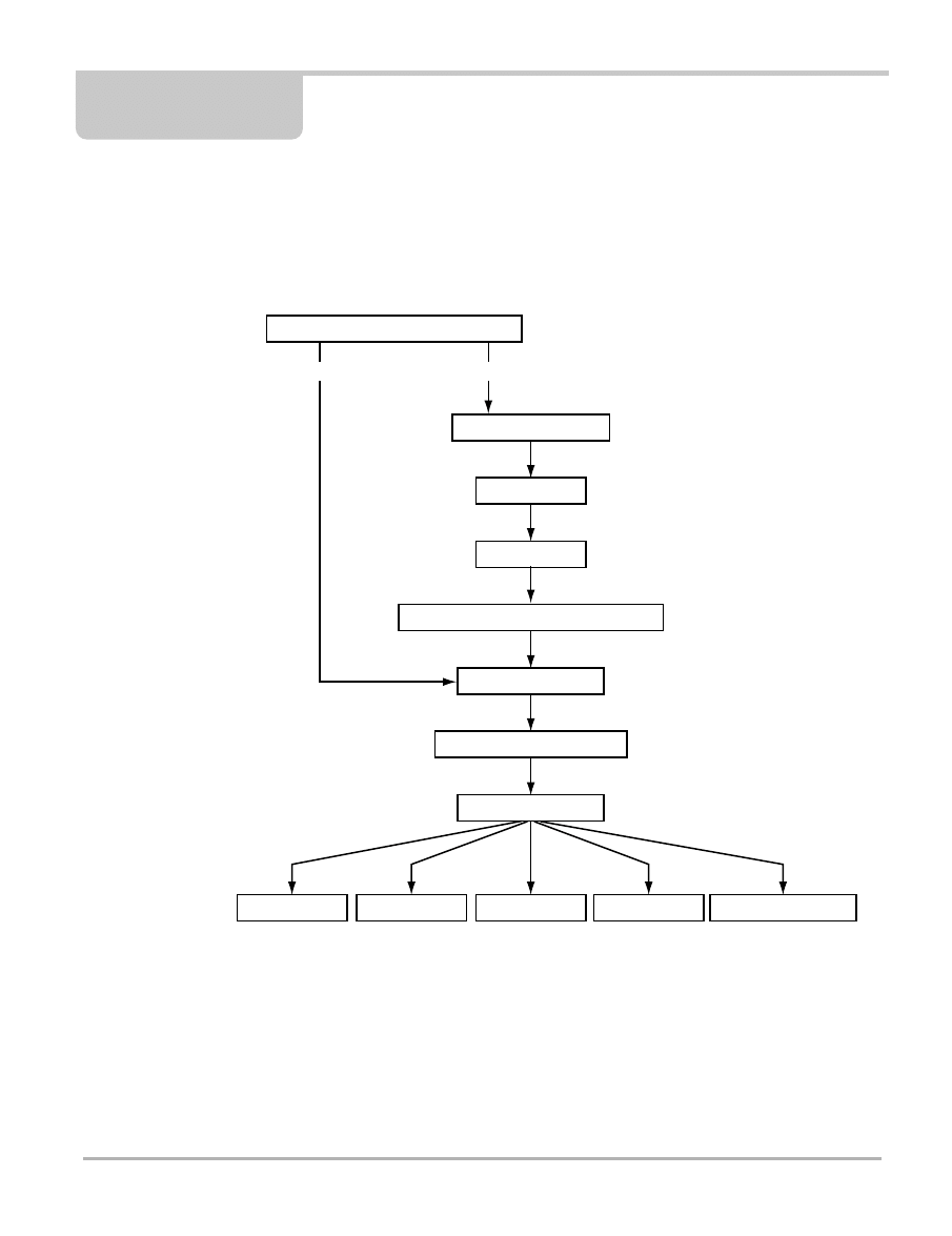
Figure 3-1
Basic Volkswagen Audi test routine
3.1 Identifying the Vehicle
The scan tool typically identifies a vehicle using certain characters of the vehicle identification
number (VIN). The scan tool vehicle identification (ID) process prompts to you enter VIN
characters and answer questions about the vehicle to be tested.
Identify the Vehicle by Entering VIN Digits
Stop Communication
Functional Tests
Review ECU ID
Codes Only
Data
Select Make
Select Market
Connect to the Vehicle
Select the System for Testing
System Main Menu
Select Volkswagen/Audi
Test the Same Vehicle?
YES
NO

5
Operations
Identifying the Vehicle
3.1.1 Engine ID Codes
The vehicle identification process includes entering the test vehicle’s engine ID code. The exact
engine ID code selection is usually not required for vehicle communications, however, in order for
the scan tool to communicate with all installed systems, we recommend that you identify the
correct engine code. The scan tool has to match all possible control module identities with the
exact control module installed in the vehicle. In addition, the engine ID code is required to select
the correct OBD-II Readiness Monitor setting procedures. See the Volkswagen/Audi OBD-II
Readiness Charts for more information.
VW/Audi specific engine differences are determined by a three-digit engine ID code. In any
particular year, there could be multiple engine ID codes for any one engine. The engine codes
may represent different horsepower, torque rating or emission package.
Engine ID codes are stamped on the engine block in three-digit alpha characters followed by a
series of numbers (usually six), for example, “AEG 029452". If more than 999,999 engines with the
same engine code are produced, the first number is replaced by a letter. Newer models may also
have an adhesive label located on the timing belt cover. The engine ID code can be difficult to
locate on older engines with excessive oil and grease. Here are typical older model 4- and
6-cylinder locations:
•
4-cylinder engine codes and numbers are usually, stamped into the rear of the cylinder block
casting near the oil filter flange near the engine/transmission joint.
•
6-cylinder engine codes are usually located on the left side of the engine block below the
camshaft timing chain tensioner. The code numbers should be visible when looking down
between the throttle valve control module and the valve cover.
Note the following when looking for an engine ID code:
•
Alternatively, look in the owners “maintenance” manual for an adhesive sticker.
•
For most engines, the engine ID code is also included on the vehicle data plate, typically
located in the trunk near the spare tire. This may be the easiest way to find the engine code.
Table 3-1 contains engine ID code locations for Audi models.
Table 3-1
Volkswagen engine ID code locations (part 1 of 4)
Model
Year
Engine
Code Location
Beetle
1999 and
later
1.8L
APH, AWP, AWV: Near the engine/transmission joint. Also on a
sticker on the toothed belt guard.
1998–2002
1.9L 4-cyl
2V TDI
ALH: Between the diesel injection pump and the exhaust manifold
on the engine block. Also on a sticker on the timing belt guard.
2003
2.0L 4-cyl
2V
BBW, BDC: On the front of the engine near the engine/
transmission joint. Also on a sticker on the cylinder head cover and
vehicle data plate.
2004 and
later
1.8L
Turbo
AWU: Unknown at this time.
BKF: The engine number can be found on the joint between
engine/gearbox.
BNU: The engine number can be found on the joint between
engine/gearbox.
1.9L TDI
BEW: The engine number can be found on the joint between
engine/gearbox.

6
Operations
Identifying the Vehicle
Beetle
(continued)
2004 and
later
(continued)
2.0L
AZG: Near the engine/transmission joint. Also on a sticker on the
cylinder head cover and vehicle data plate.
BDC: Front of the engine near the engine/transmission joint. Also
on a sticker on the cylinder head cover and vehicle data plate.
BER: Unknown at this time.
BEV: The engine number can be found on the flange between
engine/transmission.
AEG: Near the engine/transmission joint. Also on a sticker on the
cylinder head cover and vehicle data plate.
AVH: Near the engine/transmission joint. Also on a sticker on the
cylinder head cover and vehicle data plate.
BHP: Unknown at this time.
BGD: The engine number can be found at the front next to the joint
between engine/transmission
Eurovan
1999 and
earlier
2.5L
AAF, ACU: Between cylinders 1 and 3 on the cylinder block. Also
on a sticker on the toothed belt guard.
2.8L
AES: Behind the cylinder head cover on the cylinder block. Also on
a sticker attached to the cylinder head cover.
2000 and
later
2.8L
AES: On the cylinder block next to the vibration damper.
2001 to
2004
2.8L
AXK: The engine code is located next to the vibration damper on
the cylinder head.
Golf, Jetta,
GTI
1999 and
earlier
2.8L VR6
2V
AFP: On the engine block next to the vibration damper. The engine
ID number is found here from 06.27.99 production and from engine
AFP-019059.
Also on a sticker on the back of the intake manifold upper section
near the vacuum connection. Remove the engine cover to view.
1999 and
later
1.8L 4-cyl
5V Turbo
AWD, AWP, AWW: Near the engine/transmission joint. Also on a
sticker on the toothed belt guard.
1.9L 4-cyl
2V TDI
ALH: Between the diesel injection pump and the exhaust manifold
on the engine block. Also on a sticker on the toothed belt guard.
2.0L 4-cyl
2V
AEG, AVH, AZG: Near the engine/transmission joint. Also on a
sticker on the cylinder head cover and vehicle data plate.
2.8L
BDF: Next to the vibration damper on the cylinder block. Also on a
sticker on the intake manifold.
2000 and
later
2.8L VR6
2V
AFP: On the engine block next to the cylinder head, beneath the
chain tensioner for the camshaft roller chain. It can be seen by
looking down between heating resistor N79 and the throttle valve
control unit. Also on a sticker on the valve cover.
2003
2.0L
BBW: Near the engine/transmission joint. Also on a sticker on the
cylinder head cover and vehicle data plate.
2004 and
later
1.8L
Turbo
BEK: Unknown at this time.
1.9L TDI
BEW: The engine number can be found on the joint between
engine/gearbox.
BKC: Unknown at this time.
BRM: Unknown at this time.
Table 3-1
Volkswagen engine ID code locations (part 2 of 4)
Model
Year
Engine
Code Location

7
Operations
Identifying the Vehicle
Golf, Jetta,
GTI
(continued)
2004 and
later
(continued)
2.0L
BEV: The engine number can be found on the flange between
engine/transmission.
BER: Unknown at this time.
BHP: Unknown at this time.
3.2L
BFM: Unknown at this time.
BML: Unknown at this time.
BJS: The engine number is located next to the vibration damper on
cylinder block under coolant pump.
2005 and
later
2.5L
BGQ: Unknown at this time.
BGP: Unknown at this time.
Passat
1995–97
1.9L 4-cyl
2V TDI
AAZ, 1Z: On the cylinder block between the diesel injection pump
and the exhaust. Also on a sticker on the toothed belt guard.
2.8L VR6
2V
AAA: On the vibration damper end of the cylinder block. Also on a
sticker on the cylinder head cover.
1998 and
later
1.8L 4-cyl
5V Turbo
AEB, ATW, AUG, AWM: On the left side of the cylinder block. Also
on a sticker on the cylinder head cover. The engine code is also
stamped on the front of the engine lifting eye (visible after removing
the cover above the fuel injectors).
2.8L V6
5V
AHA, ATQ: On the flat surface of the cylinder block, on the front of
the right cylinder head.
W8, 4.0L
BDP: On the left of the cylinder block. Also on a sticker on the
cylinder head cover.
2004 and
later
2.0L
BHW: The engine number can be found on the joint between
engine/transmission.
BGW: Unknown at this time.
2.8L
AMX: Unknown at this time.
BBG: Unknown at this time.
4.0L
BDN: Unknown at this time.
3.2L
AZZ: Unknown at this time
BKJ: Unknown at this time
BAA: The engine number is located next to the vibration damper
on cylinder block under coolant pump.
BMX: The engine number is located next to the harmonic balancer
on the cylinder block under the coolant pump
Touareg
2004 and
later
4.2L
AXQ: The engine number is stamped on the right side of the
cylinder block.
BHX: The engine number is stamped on the right hand side of the
engine block.
5.0L TDI
AYH: Unknown at this time.
BKW: The engine number is located on the cylinder below the
cylinder head of cylinder bank 2.
Phaeton
2004 and
later
4.2L
BGJ: The engine number is stamped on the right side of the
cylinder block
BGH: The engine number is stamped on the right side of the
cylinder block
6.0L
BAP: The engine number is located at left on cylinder block
BAN: Unknown at this time.
BRP: The engine number is located at left on cylinder block
Table 3-1
Volkswagen engine ID code locations (part 3 of 4)
Model
Year
Engine
Code Location

8
Operations
Identifying the Vehicle
New Jetta
2005 and
later
1.9L TDI
BRM: The engine number can be found on the joint between
engine/transmission.
2.5L
BGP: The engine code and serial number are located on the
backside of the engine, above the separation point of the engine
block/upper point of oil pan.
BGQ: The engine code and serial number are located on the
backside of the engine, above the separation point of the engine
block/upper point of oil pan.
Table 3-2
Audi engine ID code locations (part 1 of 3)
Model
Year
Engine
Code Location
A4
1998 and
later
1.8L 4-cyl
5V Turbo
AUG, AWM: On the left side, on the cylinder head. Also on a sticker
with the on the cylinder head. The engine ID code is also stamped
on the front of the engine lifting eye (visible after removing the
cover above the fuel injectors).
2001
1.8L
AEB, ATW: On the left side of the cylinder block between the
transmission and above the oil filter. Also on a sticker on the timing
belt guard. The engine ID is also stamped on the front of the engine
mounting bracket (visible after removing cover above fuel
injectors).
2.8L
AFC: On the right-hand side of the engine block between the
cylinder head and the power steering pump. Also on a sticker on
the drive belt cover.
AHA, ATQ: On the block in front of the right cylinder head.
AHA Only: In vehicles with VINs up to 8D-V-205 000, the oil pump
is mounted on the front of the engine and driven directly by the
crankshaft. In vehicles with VINs from 8D-V-205 001 on, the oil
pump is driven via a chain by the crankshaft and mounted inside
the oil pan. Also, oil supply lines are mounted on the camshaft
bearing caps.
2003
4.2L
BHF: On the right of the intake manifold.
2003 and
later
1.8L
AMB: On the rear left of the cylinder block. Also on a sticker on the
toothed belt guard and stamped on the front lifting eye (visible
when engine cover panel is removed).
3.0L
AVK: Remove the front engine cover; there is a sticker with the
engine code and production number on the housing for vacuum
diaphragm for intake manifold adjustment. If the sticker is not
present and the engine identification is required, remove the rear
engine cover; engine codes are stamped on the rear of the cylinder
block, left side.
If there is no sticker and the engine identification and production
number are required, remove the bolts and the vacuum diaphragm
for intake manifold adjustment, then remove the compression
spring which is behind it and set off to the side of the vacuum
diaphragm with connected lines; the engine code and production
number are located at the front of the cylinder head, on top.
Table 3-1
Volkswagen engine ID code locations (part 4 of 4)
Model
Year
Engine
Code Location

9
Operations
Identifying the Vehicle
A4
(continued)
2004 and
later
1.8 L
Turbo
BKB: Unknown at this time.
BFB: Unknown at this time.
BEX: Unknown at this time.
1.8 L
Turbo
AMB: The engine number can be found on the rear left of the
cylinder block.
2.0L
BPG: The engine number can be found on the joint between
engine/transmission.
3.0L
ASN: Unknown at this time.
BBJ: Unknown at this time.
3.2L
BKH: The engine number is located on the front of the cylinder
block below the right cylinder head.
4.2L
BBK: Unknown at this time.
4.2L
BHF: A sticker arrow with engine code and serial number is located
on the intake manifold on the right side.
A6
1998 and
later
2.7L, 2.8L
APB, AHA, ATQ: On the machined surface on the cylinder block,
at the front of the right cylinder bank.
4.2L
ART, AWN, BBD: On the left side of the cylinder block. Also on a
sticker on the belt cover.
2000 and
later
3.0L
AVK: Remove the front engine cover; there is a sticker on the
housing for the vacuum diagram for intake manifold adjustment.
Also if the rear engine cover is removed engine codes are stamped
on the rear of the cylinder block, left side.
4.2L
AWN: Unknown at this time.
BBD: The engine number is located at left on the cylinder block.
2002 and
later
3.0L
ASN: Unknown at this time.
BBJ: Unknown at this time.
3.2L
BKH: The engine number is located on the front of the cylinder
block below the right cylinder head.
2004 and
later
2.7L
BES: Unknown at this time.
4.2L
ANK: Unknown at this time.
ASG: Unknown at this time.
BNK: A sticker with the engine and serial number is affixed to the
cylinder head cover on the right hand side.
A6/S6
Sedan
(1995–97)
2.2L
AAN: On the right-hand side at the rear of the cylinder head.
2.7L
BEL: On the cylinder block at the front of the right cylinder bank.
Wagon
(1995–98)
2.2L
AAN: On the right-hand side at the rear of the cylinder head.
2.7L
BEL: On the cylinder block at the front of the right cylinder bank.
2003
4.2L
BAS: On the right-hand side at the rear of the cylinder head.
BCY: On top of the cylinder block. Also on a sticker on the drive
belt cover.
A8
2004 and
later
4.2L
BFM: The engine number is located at left on cylinder block.
6.0L
BHT: Unknown at this time.
BSB: The engine number is located on the front of the cylinder
block below the left cylinder head
Table 3-2
Audi engine ID code locations (part 2 of 3)
Model
Year
Engine
Code Location

10
Operations
Identifying the Vehicle
A8/S8
4.2L
AKB, AUX, AYS: On the left side of the cylinder block. Also on a
sticker on the belt cover.
3.7L, 4.2L
ABZ, AEW: On the left side of the cylinder block directly above the
power steering pump. Also on a sticker on the toothed belt guard.
Cabriolet
2.8L
AAH, AFC: On the right-hand side of the engine block between the
cylinder head and the power steering pump. Also on a sticker on
the drive belt cover.
S4
2000
1.8L
AEB, ATW: On the left side of the cylinder block between the
transmission and above the oil filter. Also on a sticker on the timing
belt guard and stamped on the front of the engine mounting bracket
(visible after removing cover above fuel injectors).
2.8L
AFC: On the right-hand side of the engine block between the
cylinder head and the power steering pump. Also on a sticker on
the drive belt cover.
AHA, ATQ: On the flat surface of the cylinder block in front of the
right cylinder head.
AHA Only: In vehicles with VINs up to 8D-V-205 000 the oil pump
is mounted on the front of the engine and driven directly by the
crankshaft. In vehicles with VINs from 8D-V-205 001 on, the oil
pump is driven via a chain by the crankshaft and mounted inside
the oil pan. Also, oil supply lines are mounted on the camshaft
bearing caps.
2004 and
later
1.8L
Turbo
AMB: Unknown at this time.
BKB: Unknown at this time.
BFB: Unknown at this time.
3.0L
ASN: Unknown at this time.
BGN: Remove the front engine cover; there is a sticker on the
housing for the vacuum diagram for intake manifold adjustment.
Also if the rear engine cover is removed engine codes are stamped
on the rear of the cylinder block, left side.
BBJ: Unknown at this time.
AVK: Remove the front engine cover; there is a sticker on the
housing for the vacuum diagram for intake manifold adjustment.
Also if the rear engine cover is removed engine codes are stamped
on the rear of the cylinder block, left side.
4.2L
BBK: Unknown at this time.
BHF: On the right of the intake manifold.
TT
2003 and
earlier
1.8L, 3.2L
AMW, ATC, AWP, BEA, BHE: At the front next to the joint between
engine and transmission. Also on a sticker on the cylinder head
cover.
2004 and
later
1.8L
BAM: Unknown at this time.
3.2L
BHE: The engine number can be found on the joint between
engine/transmission.
Table 3-2
Audi engine ID code locations (part 3 of 3)
Model
Year
Engine
Code Location

11
Operations
Connecting to a Vehicle
3.1.2 Vehicle Identification
If you are powering up the scan tool after just installing the VAG software, or if you exited from the
Current Vehicle Identification screen, the Software Selection screen displays.
z
To enter vehicle identification:
1.
Select to continue.
The Manufacturer Selection menu displays.
2.
Select the manufacturer.
Though you are able to select Seat or Skoda, these options apply to European vehicles only.
Select Audi or Volkswagen for US vehicles.
When you select a manufacturer, a systems selection screen displays.
NOTE:
i
This is also the screen where you may select Expert Mode. See “Chapter 4 Expert Mode” on
page 18 for instructions on using Expert Mode, or continue on to the next step for standard scan
tool operations.
3.
Select Vehicle Systems US.
The Vehicle Identification screen displays.
When testing vehicles in the United States, always choose the option with “US” at the end
when available, unless you are in Expert Mode.
4.
Select the correct year for the vehicle.
The display now shows the model year you just selected and asks for the selection of the
model type.
5.
Enter any further VIN character requests and answer any yes or no questions.
At the end of vehicle identification, the scan tool displays the complete model and engine
identification.
6.
If the ID is correct, continue to store the identification in memory. If the ID is not completely
correct, exit to return to the start of the identification steps.
3.2 Connecting to a Vehicle
Once a vehicle has been identified, a scan tool connection message appears, instructing you to
use the supplied vehicle test adapters to connect the scan tool for testing.
IMPORTANT:
Before connecting the scan tool to 1997 and later vehicles, read “The Aftermarket Radio Problem”
on page 154 in order to avoid seriously damaging your scan tool.
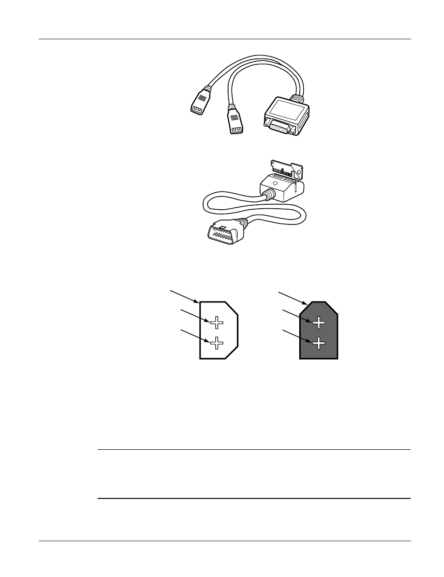
The following adapters are available to connect the scan tool to VW/Audi vehicles:
•
VW-1—test adapter for 1991–94 VW and Audi vehicles. Hooks up to the white/black
connector only (Connector for 1991–94 vehicles requires VW1 adapter).
•
DL-16—test adapter with Personality Key S-7 for 1994 and later vehicles (DL). This OBD-II
style connector is used for all vehicles. The S-44 key is used for CAN communications.
12
Operations
Connecting to a Vehicle
Figure 3-2
VW-1 adapter
Figure 3-3
DL-16 adapter with S-7 Personality Key
The following vehicle connectors are found on VW/Audi vehicles.
1— White connector
2— Blue (“K”)
3— Yellow (“L”)
4— Black connector
5— Red (+12)
6— Black or Brown (ground)
Figure 3-4
Connector for 1991–94 vehicles, requires VW-1 adapter
NOTE:
i
There may be other connectors with the white/black connector. Audi may have a yellow (A/T blink
codes) or blue (not used) connector, and VW may have a red connector for Airbag I systems. It
may be possible to hook the white connector of the VW-1 adapter to these other connectors and
read codes (without definitions).
1
2
3
4
5
6

13
Operations
Connecting to a Vehicle
Figure 3-5
16-pin OBD-II connector, requires DL-16 adapter
Refer to Table 3-3 for Volkswagen diagnostic connector locations and to Table 3-4 for Audi
diagnostic connector locations.
Follow the on-screen connection instructions to connect to the vehicle.
Table 3-3
Volkswagen diagnostic connector locations (part 1 of 2)
Model
Year
Connector Location
Cabrio
1994–97
On the instrument panel center section, on the right side of the
ashtray, behind the cover. To access, remove the ashtray and
slide the cover off.
Cabriolet
1991–93
(California only)
Manual transmission: On the center console under the shifter
boot. To access, pull firmly to dislodge the boot.
Automatic transmission: On the center console under the
selector indicator cover. To access, remove the handle from the
shifter, and then unsnap the indicator cover. The shifter can also
be lifted up and turned without removing the handle.
Corrado
All
Manual transmission: On the center console under the shifter
boot. To access, pull firmly to dislodge the boot.
Automatic transmission: On the center console under the
selector indicator cover. To access, remove the handle from the
shifter, and then unsnap the indicator cover. The shifter can also
be lifted up and turned without removing the handle.
Eurovan
1992–93
Behind the parcel shelf. To access, release the catch button, pull
the shelf out from top, and lift out.
1994
One of three locations: (1) behind the fold-down storage panel in
front of the relay/fuse panel, (2) behind the panel in the
dashboard, or (3) under the steering column.
1995–2003
Under the steering column.
Eurovan
Winnebago
Camper &
Rialta
1995
Behind the parcel shelf. To access, release the catch button, pull
the shelf out from top, and lift out.
Fox
1991–93
(California only)
On the center console under the shifter boot. To access, pull firmly
to dislodge the boot.
1
2
3
4
5
6
7
8
9
10 11 12 13 14 15 16

14
Operations
Connecting to a Vehicle
Golf/Jetta/GTI
1990–92
Manual transmission: On the center console under the shifter
boot. To access, pull firmly to dislodge the boot.
Automatic transmission: On the center console under the
selector indicator cover. To access, remove the handle from the
shifter, and then unsnap the indicator cover. The shifter can also
be lifted up and turned without removing the handle.
1993
On the instrument panel center section, below the heater controls
behind the blank switch covers.
1994
One of two locations: (1) on the instrument panel center section,
below the heater controls behind the blank switch covers, or (2) on
the instrument panel center section, on the right side of the
ashtray, behind the cover.
1995–97
On the instrument panel center section, on the right side of the
ashtray, behind the cover. To access, remove the ashtray and
slide the cover off.
1998–2004
One of two locations: (1) below the dashboard near the hood
release, or (2) on the instrument panel center section, below
heater controls behind blank switch covers.
Passat
1993–94
Manual transmission: On the center console under the shifter
boot. To access, pull firmly to dislodge the boot.
Automatic transmission: On the center console under the
selector indicator cover. To access, remove the handle from the
shifter, and then unsnap the indicator cover. The shifter can also
be lifted up and turned without removing the handle.
1995–97
On the instrument panel, on the right side of the steering wheel,
behind the cover.
1998–2005
One of two locations: (1) below the dashboard near the hood
release, or (2) between the front seats near the parking brake
under a rubber cover.
New Jetta
2004-2005
Connector located near bonnet release handle.
Touareg
2004-2005
Connector located near bonnet release handle, behind cover.
Phaeton
2004-2005
Connector located near bonnet release handle.
New Beetle
1998-2005
Connector located near bonnet release handle.
Table 3-4
Audi diagnostic connector locations (part 1 of 2)
Model
Year
Connector Location
100/A6
1992–97
One of two locations: (1) in the fuse box under the hood near the
firewall, or (2) between the front seats near the parking brake
under a rubber cover.
200/V8
1990–94
One of three locations:
(1) under the carpet in the passenger side footwell
(2) in the fuse box under the hood near the firewall
(3) between the front seats near the parking brake under a rubber
cover.
Table 3-3
Volkswagen diagnostic connector locations (part 2 of 2)
Model
Year
Connector Location

15
Operations
Selecting a System
Note the following when connecting to VW/Audi vehicles:
•
“Bonnet” is European for hood.
•
Do not assume that the scan tool ID screen is correct if the scan tool communicates. If there
are multiple selections, the scan tool will automatically identify the electronic control module,
which means that scan tool communication does not depend on a correct engine ID code
selection.
3.3 Selecting a System
Once you have confirmed a vehicle identification and connected to a vehicle (see previous
sections), the Select System menu displays.
The items that appear on this menu vary depending on the vehicle you are testing, however, not
all of the systems will be present—some of them are optional and others are mutually exclusive.
For example, when an integrated immobilizer is present, there will be no separate immobilizer
available.
NOTE:
i
Some early control modules may require an engine speed below 2000 RPM and a closed throttle
(closed CTP switch) to initialize communication. However, once communication has initialized,
higher engine speeds have no effect.
90
1993–95
In the fuse box under the hood near the firewall.
A3
1997–2003
Under the dashboard.
A4
1996–2001
One of two locations: (1) under the dashboard, or (2) under the
sliding cover in the rear ashtray.
2002–05
Under the dashboard.
A6/Allroad/S6/
RS6
1998–2005
One of two locations: (1) under the dashboard, or (2) between the
front seats near the parking brake under rubber cover.
A8
1997–2005
Under the dashboard.
Cabriolet
1994–1999
One of three locations: (1) in the fuse box under the hood near the
firewall, or (2) under the sliding cover in the rear ashtray, or (3)
under the dashboard.
2004-2005
Connector located near bonnet release handle.
S3
1999–2003
Under the dashboard.
S4/S6
1992–95
One of two locations: (1) in the fuse box under the hood near the
firewall, or (2) between the front seats near the parking brake
under a rubber cover.
S4/RS4
2000–02
One of two locations: (1) under the dashboard, or (2) under the
sliding cover in the rear ashtray.
2003
Under the dashboard.
S8
2001–02
Under the dashboard.
TT
2000–03
Under the dashboard.
Table 3-4
Audi diagnostic connector locations (part 2 of 2)
Model
Year
Connector Location

16
Operations
Selecting a System
The following systems can be selected for VW/Audi vehicles:
•
Engine Management
•
Electronic Instrument Panel
•
Abs/eds/esp/tcs
•
Airbag/pretensioners
•
Airbag Usa Golf-cabrio
•
Air-conditioning
•
Alarm System Interior
•
Audio System
•
Automatic Transmission
•
Central Door Lock System
•
Immobilizer (Separated)
•
Immobilizer (If Not Separated)
•
Steering Wheel Electronics
•
Steering Help (Separated)
•
Steering Help (If Not Separated)
•
4wd Electronics
•
Comfort Systems
•
Seat Adjustment Driver’s Side
•
Seat & Mirror Adjusting
•
Central Electronic Unit
•
Can Bus Interface
•
Add. Heater/parking Heater
•
Electronic Level Control
•
Level Control Xenon Lights
•
Tire Pressure Monitoring
•
Parking Help
•
Radio
•
Navigation Systems
•
Electronic Roof Control
•
Distance Control
•
Suspension Electronics
•
Back Spoiler
•
Emergency Control
•
Speech Control
•
Light Control Left
•
Light Control Right
•
Auto Light Switch
Note the following when selecting a VW/Audi system for testing:
•
If a system is listed on the Select System menu, that does not mean it is installed on the
vehicle. To determine the installed systems, perform an Automatic System Test in Expert
Mode (see “00-Automatic System Test” on page 20).

17
Operations
Demonstration Programs
•
“Separated” means a standalone control module. “Not Separated” means that the system is
integrated with another control module.
•
The 25-Immobilizer (Separated) and 44-Steering Help (Separated) systems can give the
following ECU identification: “Bitte Adresse 17 eingeben”. This means that the selected
system is integrated in the instrument panel and that you need to select 17-Electronic
Instrument Panel for diagnostics. Although it is possible to continue and select the functions,
the information retrieved is not valid.
•
The numbers that precede each system selection (i.e., “01” in front of “Engine Management”)
are for use with the manufacturer scan tool only. These numbers are not used for Snap-on
®
scan tool operations.
z
To select a system for testing:
1.
Select the system you would like to test.
An instructions screen displays.
2.
Follow the on-screen instructions to continue.
The Connection In Progress screen displays while the scan tool attempts to communicate
with the vehicle.
3.
When the scan tool communicates with the vehicle, accept the defaults until the Main Menu
displays.
3.4 Demonstration Programs
The Volkswagen/Audi software contains programs that demonstrate test capabilities without
connecting to a vehicle. The demonstration program can help you become familiar with scan tool
menus and operation by providing mock data and test results for a sample vehicle ID.
The demonstration program is accessed at the vehicle identification phase of scan tool
operations.
z
To access a demonstration:
1.
Select Demonstration US.
A screen displays, prompting you to identify a vehicle with “Demo” on line 1.
2.
Select the defaults until the System Selection menu displays.
You are now in demonstration mode.
18
Chapter 4
Expert Mode
In addition to providing the same capability as standard or vehicle ID mode, Expert Mode has
enhanced factory tool capabilities, giving the user special functions, such as setting adaptations
and control module coding. Scan tool display screens in Expert Mode give no information about
the specific procedures nor how to perform these special functions. Aftermarket information is
limited in performing these functions. Expert Mode should only be used if the user is experienced
in Volkswagen or Audi diagnostics and has the required information.
IMPORTANT:
It is possible to change and clear system settings with this function. Some functions can be
disabled and/or the control module could be corrupted by incorrect use!
IMPORTANT:
Expert Mode functionality in this manual describes only the basic operation of some of the
capabilities. Factory procedures for specific vehicles and systems must be followed to prevent any
damage or inadvertent change in critical driveability, security and safety settings. For example,
adaptation functions can disable or enable airbags, a major liability to a shop should there be a
future accident with this vehicle.
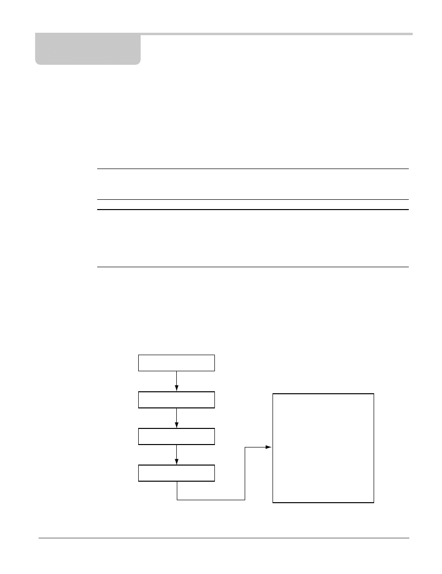
4.1 Using Expert Mode
This section explains how to start using Expert Mode. The following is an outline of scan tool
Expert Mode operation, starting with identifying the vehicle. Step 2 is described in “Chapter 3
Operations” on page 4.
Figure 4-1
Expert Mode basic operations
01-Read ECU Identification
02-Check DTC Memory
03-Actuator Tests
04-Basic settings
05-Clear DTC Memory
06-Stop Communication
07-ECU Coding
08-Read Measuring Value Block
09-Read ADC Channel
10-Adaptation
11-Login Request
15-Check readiness Code Setting
16-Security Access
Select a System to Test
Connect to the Vehicle
Select Expert Mode
Select a Function

19
Expert Mode
Using Expert Mode
The remaining steps are described in greater detail in this chapter.
1.
Select Expert Mode—Instead of selecting Vehicle Systems US as you would for standard
scan tool operations, select Expert Mode. See “Initiating Expert Mode” on page 19.
2.
Connect the scan tool—Follow the connection instructions displayed after selecting Expert
Mode to connect the scan tool with the vehicle. See “Connecting to a Vehicle” on page 11.
3.
Select the system—Enter the system to be tested (engine, transmission, ABS, etc.). See
“Selecting a System” on page 19.
4.
Select the Expert Mode function—The scan tool displays the functions available on the
identified vehicle electronic control module. Select the appropriate functions for the vehicle
you have identified. See “Expert Mode Function Selection Menu” on page 20.
4.1.1 Initiating Expert Mode
After you have selected a manufacturer, you can initiate Expert Mode.
z
To initiate Expert Mode:
1.
Select Expert Mode.
A warning screen displays.
2.
Select to continue.
Instructions to connect the scan tool to the vehicle display.
See “Connecting to a Vehicle” on page 11 for information about connecting the scan tool to
VW/Audi diagnostic connectors, or ID the vehicle in standard mode (see “Identifying the
Vehicle” on page 4) until model-specific connection instructions display.
3.
Connect to the correct diagnostic connector on the vehicle, then continue.
The System Selection menu displays.
4.1.2 Selecting a System
There are two special items on the Expert Mode System Selection menu that do not display on the
standard System Selection menu:
•
00-Automatic System Test
•
01-Engine Management Master (11-Engine Management Slave is not used for US vehicles)
The rest of the items on the menu are the same as in standard mode (“Selecting a System” on
page 15).
z
To select a system for testing:
1.
Select the system you would like to test.
The communication instruction screen displays.
NOTE:
i
Selecting 00-Automatic System Test displays a different screen (see 00-Automatic System Test).
2.
Select to continue.
A warning message displays.

20
Expert Mode
Using Expert Mode
3.
Select to continue.
The scan tool displays the vehicle’s electronic control module identification.
4.
Select to go to the Expert Mode Function Selection menu (see “Expert Mode Function
Selection Menu” on page 20).
00-Automatic System Test
The Automatic System Test is always the first menu choice in Expert Mode. This selection
interrogates all installed controllers and automatically prints out all control module IDs and any
DTCs stored there.
NOTE:
i
A printer must be connected for an Automatic System Test to run.
This test may take ten minutes or longer depending on the number of control modules. DTCs may
be set in multiple controllers, therefore, all control modules need to be checked for DTCs and have
DTCs cleared after repairs. Automatic System Test is a good way to know which controllers are
installed on the vehicle and to obtain DTC information.
z
To perform an Automatic System Test:
1.
Select 00-Automatic System Test from the System Selection menu. A screen displays,
prompting you to select Y to begin the test or N to return to the previous menu.
2.
Select to begin the Automatic System Test. The Printing in progress screen displays.
The scan tool prints the result when the test is finished.
4.1.3 Expert Mode Function Selection Menu
When the scan tool has established a connection with the vehicle, the scan tool displays a
Function Selection menu, such as the Expert Mode Function Selection menu.
The Expert Mode Function Selection menu allows you to select from the following general
functions:
•
01-Read ECU Identification—displays the control module identification string, the control
module coding, and Work Shop Code (see page 21).
•
02-Check DTC Memory—displays all current diagnostic trouble codes present (see
page 22).
•
03-Actuator Tests—activates different actuator tests for about 30 seconds in sequence (see
page 22).
•
04-Basic Setting—performs a Basic Setting, depending on the entered block number (000–
255) (see page 22).
•
05-Clear DTC Memory—clears any existing trouble codes and checks if the trouble codes
are really cleared (see page 22).
•
06-Stop Communication—stops the communication and exits Expert Mode (see page 22).
•
07-ECU Coding—changes the existing control module coding by entering a new coding (see
page 23).

21
Expert Mode
Using Expert Mode
•
08-Read Measuring Value Block—displays measuring value blocks after entering a valid
block number (see page 23).
•
09-Read ADC Channel—displays data from a single ADC channel (see page 27).
•
10-Adaptation—changes adaptation values from the control module (see page 27).
•
11-Login Request—performs a login request to the control module after entering a valid login
code (see page 28).
•
15-Check Readiness Code Setting—displays a readiness code and whether it is set or not
(see page 28).
•
16-Security Access— performs a security access request to the control module (see
page 29).
Note the following when using Expert Mode:
•
There is no Custom Setup available in Expert Mode (for example, you cannot change the
temperature readings from Celsius to Fahrenheit).
•
There are no Movie or Print Frame options, only Print Screen and Print Codes. Printer
communication settings must be configured in standard mode using vehicle ID or in
Demonstration mode to have the possibility to print. Expert Mode also will not work with
Snap-link™ or ScanGrafix PC graphing programs.
•
When using Expert Mode, supplemental information found in VAG service manuals is
necessary to interpret displayed data values and to know the proper procedure to perform a
specific test, coding, or adaptation.
01-Read ECU Information
This function displays the control module identification string, the control module coding, and
Work Shop Code. Also, some systems will display some extra control module identification if
selected.
VW/Audi part numbers for this controller contain a version number for the controller's internal
firmware. Shop number identifies the Work Shop Code stored in the scan tool that last recoded
this control module.
NOTE:
i
Some older control modules are not “codeable” and you may see a Bosch part number or other
information in theses fields.
The Extra ECU identification fields can store VIN and immobilizer information on some vehicles.
Work Shop Code
World Wide, every VW/Audi dealer is assigned a unique Work Shop Code (WSC). Factory scan
tools require a valid WSC to function, and once it has been entered, it cannot be changed.
Whenever a control module is coded, or adaptations are performed, the scan tool sends its WSC
to the control module and the control module records it. If a factory scan tool was used to perform
specific functions, such as disabling an airbag through the WSC, it may be possible to identify
which dealer performed this procedure.

22
Expert Mode
Using Expert Mode
NOTE:
i
The Snap-on
®
VAG software does not change or alter the WSC. It reads the existing WSC and
sends it back unchanged after a procedure has been performed.
02-Check DTC Memory
This function displays all diagnostic trouble codes (DTCs) currently present or stored in memory.
03-Actuator Tests
This function activates different actuator tests for about 30 seconds in sequence, or depending on
the ECU you may select which available test to run. The user can abort or continue to the next test.
Some tests display a command to the user. For example, if “Press Brake Pedal” displays, the user
has to press and hold the brake pedal and then continue. The sequence, number, and type of tests
are dictated by the control module.
To perform the actuator tests, the entry conditions must be correct. For the correct entry conditions
refer to the VAG system specific workshop manual. On some systems, the actuator tests cannot
be restarted until the ignition key is switched off for some time. Alternatively, briefly start and run
the engine, shut down, turn the ignition to the run position, then re-initiate the actuator tests.
04-Basic Settings
This function can put a system in basic mode or performs a Basic Setting. This depends on the
entered block number (000–255). After entering a valid block number, data values or text can be
displayed. There is no description of the data value, only the value and unit is displayed. For
interpretation of the values, refer to the VAG system-specific workshop manual. See “Basic
Settings” on page 45 for more information.
05-Clear DTC Memory
This function attempts to clear all current and stored DTCs. After clearing, the scan tool rechecks
for DTCs, and any that reset from current problems will re-display.
06-Stop Communication
This function stops the communication and leaves the Expert Mode. If the scan tool gets
accidently disconnected, go back to the same controller and then exit properly using 06. This is
the equivalent of selecting Other Systems in standard mode.
IMPORTANT:
Always exit out of any one module using 06-Stop Communication before selecting another
module. Failure to do so may cause communication problems, corrupt data, or cause a parasitic
draw on the battery.

23
Expert Mode
Using Expert Mode
07-ECU Coding
This function can change the existing control module coding by entering a new coding. The range
of coding can be 0–127, 0–32767 or 0–1048575. The coding number can tell a control module
about the configuration, for example, if cruise control is available or not.
After entering a new coding, it is sent to the control module and the scan tool reports if the new
coding is accepted or not. A coding will not be accepted if it is an unknown number or if a control
module cannot be coded. However, be aware that a control module usually does accept an
incorrect coding number.
Some special codings require an unlocked control module. The control module can be unlocked
with a Log-in or Security Access request.
Note the following regarding control module coding:
•
The following login information is subject to change and is not guaranteed to work on every
application. A common VW login is 01283; a common Audi login is 13861. Specific vehicle
logins are found in that vehicle’s service manual.
•
2002 vehicles using the new CAN Bus communication network may not require control
modules to be version coded, as the version coding information is obtained from the other
controllers sharing the CAN Bus. However, if the engine control module is replaced it will need
to be adapted to the immobilizer (see “Testing Immobilizer Systems” on page 75).
08-Read Measuring Value Block
This function displays measuring value blocks. After entering a valid block number, data values or
text are displayed. There is no description of the data value, only the value and unit is displayed.
For interpretation of the values, refer to the VAG system specific workshop manual. Press N to
enter the print exit menu. Scroll to change the block number. The displayed data is the actual data
received from the control module.
VW/Audi Display Group Data
Instead of one long data list, VW and Audi data is organized into display groups (Table 4-1).
However, these groups are not determined by a scan tool. Instead, these are manufacturer
predetermined groups which change depending on the vehicle and engine. Table 4-1 provides
some examples of group categories available on a late model VW and Audi.
Table 4-1
VW/Audi display group categories (part 1 of 2)
Display Group Number
Display Group Category
1–9
General engine activity data
10–19
Ignition
20–29
Knock control
30–39
O2 sensor control system
40–49
Three-way CAT
50–59
Engine speed control
60–69
Throttle drive
70–79
Emissions reduction
80–89
Special function
90–97
Power increase

24
Expert Mode
Using Expert Mode
The following sections provide information that give examples of engine data interpretation. Note
that data available varies by year, engine, engine code, and management system.
NOTE:
i
The display groups available using vehicle ID may vary from the total number of display groups
available in Expert Mode. Display groups in standard vehicle ID mode are preselected based on
priority of use. All possible display groups can be viewed using Expert Mode. To view a particular
display group in Expert Mode, the specific group number must be manually entered.
The following examples may have additional display groups available in Expert Mode.
Example 1: 2002 VW Jetta Drive-by-Wire, Bosch ME 7.5 Control System
•
Group=1, Basic Functions (1)
•
Group=2, Basic Functions (2)
•
Group=3, Basic Functions (3)
•
Group=4, Basic Functions (4)
•
Group=5, Operating Mode Engine
•
Group=6, Altitude Correction
•
Group=10 Ignition
•
Group=20, Ignition, Knock Control Cyl 1-4
•
Group=22, Ignition, Knock Control Cyl 1+2
•
Group=23, Ignition, Knock Control Cyl 3+4
•
Group=28, Knock Control
•
Group=30, O2 Status
•
Group=32, Learn Values O2
•
Group=33, O2 Regulation Before Cat
•
Group=37, Diagnose O2 Control System
•
Group=41, O2 Sensor Heater
•
Group=50, Idle Speed Control
•
Group=54, Idle Speed Control
•
Group=55, Idling Stabilization (1)
•
Group=56, Idling Stabilization (2)
•
Group=60, Adaptation Epc-system
•
Group=61, Epc-system (1)
•
Group=62, Epc-system (2)
•
Group=99, O2 Loop
98–100
Compatibility
101–109
Fuel Ignition
110–119
Boost pressure control
120–129
Control unit communication
130–150
Special info
Table 4-1
VW/Audi display group categories (part 2 of 2)
Display Group Number
Display Group Category

25
Expert Mode
Using Expert Mode
Example 2: 2002 Audi TT Drive-by-Wire, Bosch ME 7.1 Control System
•
Group=1, Basic Functions (1)
•
Group=2, Basic Functions (2)
•
Group=4, Basic Functions (3)
•
Group=5, Basic Functions (4)
•
Group=6, Basic Functions (4)
•
Group=10, Ignition
•
Group=22, Ignition, Knock Control Cyl 1+2
•
Group=23, Ignition, Knock Control Cyl 3+4
•
Group=28, Diagnose Knock Sensors
•
Group=30, O2 Status
•
Group=32, Learn Values O2
•
Group=33, O2 Regulation
•
Group=41, O2 Sensor Heater
•
Group=50, Idle Speed Control
•
Group=54, Idle Speed Control
•
Group=55, Idling Stabilization
•
Group=56, Idling Stabilization
•
Group=60, Adaptation Epc-system
•
Group=60, Throttle Valve Adjuster
•
Group=61, Throttle Valve Adjuster
•
Group=62, Epc-system
•
Group=63, Kickdown Function
•
Group=66, Cruise Control Status
•
Group=99, O2 Loop
•
Group=113, Control Turbo Pressure
•
Group=114, Control Turbo Pressure
•
Group=115, Control Turbo Pressure
•
Group=117, Control Turbo Pressure
•
Group=118, Control Turbo Pressure
•
Group=120, Tcs System
•
Group=125, Can Bus Communication
Example 3: Motronic 2.9 (1993–1995)
Display group 000 has 10 channels or display fields, listed below.
1.
Coolant temperature
2.
Engine load
3.
RPM
4.
O2 factor
5.
Idle Adapt
6.
Part throttle adapt
7.
Low load adapt

26
Expert Mode
Using Expert Mode
8.
IAC adapt
9.
Not used
10. IGN timing
The display fields are output in binary numbers. To understand the binary number, visualize a
clock with 0 at the top center. The number 128 is at the center bottom. The binary clock counts
from 0 to 255, a rich/lean correction from base midpoint (0).
In binary output 0–255, based on O2S output, numbers fluctuate between rich (high numbers) and
lean (low numbers).
The number can theoretically range from 0 to 255 with 0 as the midpoint. A number of 13 to 128
indicates that the control module has commanded an overall lean mixture correction. A number of
128 to 243 indicates that the control module has commanded an overall rich mixture correction.
Example 4: Late Model Motronic 7.5
The following example concerns display group 000 for 1-bank systems:
1.
Engine coolant temperature
2.
Load
3.
RPM
4.
Voltage
5.
Throttle valve potentiometer
6.
Idle air control valve
7.
Idle air control valve learning value
8.
Lambda control
9.
Lambda control learning value idle
10. Lambda control learning value partial load
Display group 000 for 2-bank systems:
1.
Engine coolant temperature
2.
Load
3.
RPM
4.
Throttle valve angle
5.
Idle air control
6.
Idle air control valve learning value
7.
Lambda control Bank 1
8.
Lambda control Bank 2
9.
Lambda adaptation (add) Bank 1
10. Lambda adaptation (add) Bank 2
Example 5: Central Electronic Unit (09)
The four display fields for display group 012 indicate the following:
•
Display field 1: Check bus—This field indicates whether the data bus is OK or faulty (e.g.
fault in single wire).

27
Expert Mode
Using Expert Mode
•
Display field 2: Equipment front—This field indicates which front control units are fitted and
participate in data transfer.
•
Display field 3: Equipment rear—This field indicates which rear control units are fitted and
participate in data transfer.
•
Display field 4: Accessories—This field indicates whether the seat and mirror adjustment
memory system is fitted. Both systems (convenience system and memory system)
interchange data.
NOTE:
i
Inter-module CAN data transfer currently cannot be checked.
09-Read ADC Channel (Except KW2000
1
)
This function displays data from a single ADC channel. This function allows you to look at real-time
data from control modules that support it. Currently, this data has no interpretation or scaling
information.
z
To set the Read ADC Channel function:
1.
Enter a valid channel number
A number from 0 to 65535 displays.
2.
Scroll to change the channel number.
10-Adaptation
This function can change adaptation values from the control module and allows you to alter certain
values and/or settings in control modules which support it.
IMPORTANT:
Function 10 changes baseline settings. Do not proceed with this function unless you know the
exact procedure. Be aware that some Channels may not be documented.
Examples of things you can do with the adaptation selection:
•
Alter the Idle Speed (e.g., 01-Engine Management > 10-Adaptation > 000/0001).
•
Change the Service Intervals and resetting the Service Reminder Indicators (newer
instrument clusters).
•
Disable/enable various components of the airbag (SRS) system.
•
Change the sensitivity of the Interior Monitor (Sonar Scan) component of the alarm system in
many newer Audi models.
•
Swap control modules and rematch keys (newer immobilizer-equipped cars).
•
Select certain Central Locking options in newer vehicles.
1
“KW2000” stands for Key Word 2000, and refers to a communication protocol which was used beginning
in 2002 on limited vehicles, such as the VW Passat 1.8L turbo, the Audi A4 1.8L and 3.0L, and the Audi
A6 3.0L.

28
Expert Mode
Using Expert Mode
To change adaptation values:
1.
Read the adaptation.
2.
Test the adaptation.
3.
Save the adaptation.
To set an adaptation:
1.
Select a valid channel.
The actual adaptation value is displayed. On some adaptation channels, there will be data
displayed on the last line.
2.
Scroll for manual input.
The new adaptation value can be tested or changed. For example, the engine speed is raised
to numbers greater than 128 or lowered to numbers less than 128.
3.
To exit and store a new value, select to confirm or abort.
Selecting channel 000 clears all adaptation values after confirming the request.
11-Login Request (Except KW2000)
This function performs a login request to the control module. After entering a valid login code, the
control module is ready to perform a special coding or adaptation function.
Used on some (mostly 1996 and later) control modules, Login Request is necessary before you
can recode or change adaptation values. On others, it “enables” certain features like cruise
control. Valid login codes can be found in the workshop manual for the car.
The following login information is subject to change and is not guaranteed to work on every
application:
•
A common VW login is 01283
•
A common Audi login is 13861
NOTE:
i
You get only one chance to enter the correct login number. If you enter the wrong number, turn off
the ignition and wait 10 seconds before another attempt.
11-ECU Coding 2 (KW2000 Only)
This function can change the special control module coding by entering a new valid coding.
15-Check Readiness Code Setting (Except KW2000)
If the system has a readiness code, this function displays that readiness code and whether it is set
or not. If the system has no special readiness block, sometimes the same information can be
found in function 08 by selecting group 86 and checking Channel 1.

29
Expert Mode
Testing in Expert Mode
16-Security Access (KW2000 Only)
This function performs a security access request to the control module. After entering a valid code,
the control module is ready to perform a special coding or adaptation function.
Note the following when using 16-Security Access:
•
The Snap-on scan tool currently performs only 5-digit security codes.
•
Some early systems cannot communicate if the engine is running.
•
Some early systems cannot communicate or communication is lost if engine or vehicle speed
exceeds a certain specification. Refer to the VAG system-specific manual for details.
4.2 Testing in Expert Mode
The functions available depend on the communication protocol. Functions that can be executed
depend on the system and entry conditions. Some functions need a login or security access
before executing the particular function. Not all systems support all functions.
NOTE:
i
The 25-Immobilizer (Separated) and 44-Steering Help (Separated) systems give the following
control module identification: Bitte Adresse 17 eingeben. Although it is possible to continue and
select the functions, the information retrieved is not valid and should be discarded. The selected
system is integrated in the instrument panel. Please select 17-Electronic Instrument Panel for
diagnostics.
For more testing information, see “Chapter 5 Testing” on page 30.

30
Chapter 5
Testing
This chapter provides information and procedures for using the scan tool with specific control
systems. Control systems discussed in this chapter are:
•
•
•
Testing Electronic Throttle Systems
•
•
•
Testing Electronic Instrument Panel Systems
•
•
5.1 VW/Audi Software Application List
Table 5-1 provides VW/Audi systems covered by the scan tool.
Table 5-1
VW/Audi software application list (part 1 of 2)
Control Systems
Codes
Data
Advanced Functions
ABS/EDL/ESP/TCS
Standard & Expert Mode
Expert Mode Only
Add. Heater/Parking
heater
Standard & Expert
Mode
Expert Mode Only
Expert Mode Only
Airbag/Pretensioners
Standard & Expert
Mode
Expert Mode Only
Expert Mode Only
Air-conditioning
Standard & Expert
Mode
Expert Mode Only
Expert Mode Only
Alarm System Interior
Standard & Expert
Mode
Expert Mode Only
Expert Mode Only
Anti-slip Control
Standard & Expert
Mode
Expert Mode Only
Expert Mode Only
Audio System
Standard & Expert
Mode
Expert Mode Only
Expert Mode Only
Auto Light Switch
Standard & Expert
Mode
Expert Mode Only
Expert Mode Only
Automatic Transmission
Standard & Expert Mode
Back Spoiler
Standard & Expert
Mode
Expert Mode Only
Expert Mode Only
CAN Bus Interface
Standard & Expert
Mode
Expert Mode Only
Expert Mode Only
Central Door Lock
Standard & Expert
Mode
Expert Mode Only
Expert Mode Only
Central Electronic Unit
Standard & Expert
Mode
Expert Mode Only
Expert Mode Only

31
Testing
VW/Audi Software Application List
Clutch Electronics
Standard & Expert
Mode
Expert Mode Only
Expert Mode Only
Comfort Systems
Standard & Expert
Mode
Expert Mode Only
Expert Mode Only
Distance Control
Standard & Expert
Mode
Expert Mode Only
Expert Mode Only
Electronic Instrument
Panel
Standard & Expert
Mode
Expert Mode Only
Standard & Expert
Mode
Electronic Level Control
Standard & Expert
Mode
Expert Mode Only
Expert Mode Only
Electronic Roof Control
Standard & Expert
Mode
Expert Mode Only
Expert Mode Only
Emergency Unit
Standard & Expert
Mode
Expert Mode Only
Expert Mode Only
Engine Management
Standard & Expert Mode
Immobilizer
Standard & Expert
Mode
Expert Mode Only
Expert Mode Only
Level Control Xenon
Lights
Standard & Expert
Mode
Expert Mode Only
Expert Mode Only
Light Control Left
Standard & Expert
Mode
Expert Mode Only
Expert Mode Only
Light Control Right
Standard & Expert
Mode
Expert Mode Only
Expert Mode Only
Navigation
Standard & Expert
Mode
Expert Mode Only
Expert Mode Only
Parking Help
Standard & Expert
Mode
Expert Mode Only
Expert Mode Only
Radio
Standard & Expert
Mode
Expert Mode Only
Expert Mode Only
Seat Adjustment
Driver Side
Standard & Expert
Mode
Expert Mode Only
Expert Mode Only
Seat and Mirror
Adjustment
Standard & Expert
Mode
Expert Mode Only
Expert Mode Only
Speech Control
Standard & Expert
Mode
Expert Mode Only
Expert Mode Only
Steering Help
Standard & Expert
Mode
Expert Mode Only
Expert Mode Only
Steering Wheel
Electronics
Standard & Expert
Mode
Expert Mode Only
Expert Mode Only
Suspension Electronics
Standard & Expert
Mode
Expert Mode Only
Expert Mode Only
Tire Pressure
Monitoring
Standard & Expert
Mode
Expert Mode Only
Expert Mode Only
4WD Electronics
Standard & Expert
Mode
Expert Mode Only
Expert Mode Only
Table 5-1
VW/Audi software application list (part 2 of 2)
Control Systems
Codes
Data
Advanced Functions

32
Testing
Testing Engine Systems
5.2 Testing Engine Systems
The following sections contain scan tool testing information for engine systems. Testing Engine
Systems first lists the VW/Audi engines that communicate with the scan tool, and continues to
provide procedures and tips for certain testing functions.
5.2.1 VW/Audi Application Coverage
The following sections contain US vehicle coverage for 1991–2005 VW and Audi.
US Volkswagen Application Coverage
Table 5-3 provides application coverage for US Volkswagen engines.
Table 5-2
VW/Audi application coverage
Volkswagen
Audi
CIS-E or K-Jetronic/CIS (1990–92)
Digifant 1 (CA only) (1991–93)
Motronic M2.9 (1993–95)
Motronic M5.9 (1995–2000)
Motronic M5.9.2 (1997–2005)
Motronic M7.0 (1999–2001)
Motronic M7.1 (2000–01)
Motronic M7.1.1 (2002–05)
Motronic M7.5 (2001–05)
Motronic M7.5.1 (2002)
Diesel TDI (1996–2003)
CIS-E or K-Jetronic/CIS (1990–92)
MPI (1990–95)
Motronic M2.3 (1991–94)
Motronic M2.3.2 (1993–95)
Motronic M2.4 (1990–94)
Motronic M2.9 (1993–95)
Motronic M5.4.2 (1995–96)
Motronic M5.9 (1996–98)
Motronic M5.9.2 (1998–2000)
Motronic ME7.1 (2000–01)
Motronic ME7.5.1 (2002–03)
Table 5-3
US VW application coverage (part 1 of 4)
Model
Year
Volume
Engine
Code
Engine Info
Supported
Notes
Cabriolet (15)
1990–92
1.8
2H
YES
CA Only
Cabriolet (1E)
1995–2001
2.0
ABA
YES
Cabriolet (1V)
2000–02
2.0
ABA
YES
Corrado (50)
1992–1995
2.8
AAA
YES
1991–92
1.8
PG
G60
YES
CA Only
Eurovan (70)
1992–95
2.5
AAF
5L
YES
1992 Canada
Only
1995
2.5
ACU
5L
YES
1995 Only
Winnebago/
Rialta
1997–2000
2.8
AES
VR6
YES
2001–04
2.8
AXK
VR6
YES
Fox (30)
1991–93
1.8
ABG
YES
CA Only

33
Testing
Testing Engine Systems
Golf/Jetta/GTI
(1G) MK II
1991–92
2.0
9A
16V
YES
1.8
PF
NO
1.8
RV
YES
CA Only
Golf/Jetta/GTI
(1H) MK III
1993–99
2.8
AAA
VR6
YES
2.0
ABA
YES
1993–97
1.8
ACC
YES
Canada Only
1998–99
1.9
IZ
TDI
YES
AHU
TDI
YES
Golf/Jetta/GTI
(1J) MKIV
1999–2002
2.8
AFP
VR6
YES
1999–2001
2.0
AEG
YES
1999–2003
1.9
ALH
TDI
YES
2000–01
1.8
AWD
Turbo
YES
2001–03
2.0
AVH
YES
1.8
AWW
Turbo
YES
2002
2.8
AFP
VR6
YES
2003–05
1.8
AWP
Turbo
YES
2.0
AZG
YES
2.0
BBW
SULEV
YES
2.8
BDF
VR6
YES
2004–05
1.8
BEK
Turbo
YES
1.9
BEW
TDI
YES
2.0
AZG
YES
BEV
YES
BER
YES
3.2
BJS
YES
BML
YES
BFM
YES
New Beetle
(1C)
1999–2000
1.8
APH
Turbo
YES
2001–05
1.8
AWV
Turbo
YES
1998–2005
1.9
ALH
TDI
YES
1998–2002
2.0
AEG
YES
2000–03
2.0
AVH
YES
2001–05
2.0
AZG
YES
2003
2.0
BDC
Convertible
YES
2004–05
1.8
AWU
Turbo
YES
AWP
Turbo
YES
1.9
BEW
TDI
YES
2.0
AZJ
YES
BDC
YES
BEV
YES
Table 5-3
US VW application coverage (part 2 of 4)
Model
Year
Volume
Engine
Code
Engine Info
Supported
Notes

34
Testing
Testing Engine Systems
New Beetle
(1C)
(continued)
2004–05
2.0
BER
YES
BGD
YES
BHP
YES
New Jetta
(9M) MK IV
1999–2001
1.8
AWD
Turbo
YES
1999–2005
1.9
ALH
TDI
YES
1999–2001
2.0
AEG
YES
2000–03
2.0
AVH
YES
AZG
YES
1999–2002
2.8
AFP
VR6
YES
2003
2.8
BDF
YES
2004–05
1.9
BEW
TDI
YES
2005
1.9
BKC
TDI
YES
BRM
TDI
YES
2000–05
2.0
AVH
YES
AZG
YES
2004–05
2.0
BBW
YES
BER
YES
BEV
YES
BHP
YES
2003-2005
2.8
BDF
YES
2005
2.5
BGP
YES
BGQ
YES
Passat (31)
1991–93
2.0
9A
16V
YES
1993–94
2.8
AAA
VR6
YES
Passat (3A)
1996–97
1.9
1Z
TDI
YES
1995–97
2.8
AAA
YES
2.0
ABA
YES
New Passat
(3B)
1998–99
1.8
AEB
Turbo
YES
1998–2000
2.8
AHA
V6
YES
2000–03
2.8
ATQ
V6
YES
1999–2001
1.8
ATW
Turbo with
variable
valve timing
YES
2003
4.0
BDP
W8
YES
2004–05
BGW
YES
2.0
BHW
YES
2.8
AMX
YES
BBG
YES
4.0
BDN
YES
Table 5-3
US VW application coverage (part 3 of 4)
Model
Year
Volume
Engine
Code
Engine Info
Supported
Notes

35
Testing
Testing Engine Systems
VW/Audi On-board Diagnostic Availability:
1990–1995 Gas, 1992–2002 Diesel
The VW/Audi software starts VW/Audi US VIN ID in 1991 (US vehicle systems) and only identifies
those vehicles with Codes and Data (does not retrieve blink codes). Table 5-4 on page 36 depicts
many early year models with some vehicles having scan tool diagnostics depending on Emission
certification or country, engine system description, including emission certification and early
systems without diagnostic capability.
Starting in 1990, VW and Audi started using digital engine management systems on some models
that were sold only in California.
Note the following when determining diagnostic availability:
•
Only some of these early systems may have codes and rapid or serial data.
•
There are some early blink code only systems not listed in Table 5-4 on page 36.
•
For 1991–93, certain engine codes have data on California (CA) models only. Federal
vehicles with the same engine code will display a “no communication” message and an
additional message stating “Federal Vehicles are not capable of communicating.” Federal
Vehicles may have blink codes.
•
If the underhood emission label is missing, distinguishing between CA or Federal vehicles
may be difficult. Also, Federal vehicles may still have the white/black diagnostic connector
(under shifter boot). This connector may not be functional or may be for transmission (4-speed
only) or ABS data. Only the 9A Federal emission equipped engine has engine data. To help
identify a CA emission engine, check for a functional Malfunction Indicator Lamp (ignition on,
engine off) or check for an exhaust gas recirculation (EGR) valve installed on the engine.
•
European IDs can be used where the VIN cannot. The following systems can not be identified
using US VIN ID. Use the alternate IDs below.
–
For the 1990 Golf/Jetta/GTI/Corrado/Passat using the 2.0L (9A) with CIS-E Motronic, ID
as a 1991 Passat or use European ID for 1990 Golf or Jetta.
–
For the 1993–1994 Golf 1.8L (ACC), ID as a 1995 model year or use European ID and
select 1993 or 1994 Golf 1.8L ACC.
Phaeton
2004–05
4.2
BGH
YES
BGJ
YES
6.0
BAN
YES
BAP
YES
Touarag
2004–05
3.2
AZZ
YES
BAA
YES
BKJ
YES
4.2
AXQ
YES
5.0
AYH
TDI
YES
BKW
TDI
YES
Table 5-3
US VW application coverage (part 4 of 4)
Model
Year
Volume
Engine
Code
Engine Info
Supported
Notes

36
Testing
Testing Engine Systems
NOTE:
i
The scan tool vehicle ID provides connector messages and system information but because the
control modules are identified automatically, an incorrect VIN or vehicle ID does not stop scan tool
communication.
In addition, be aware that Expert Mode can also be used on any vehicle with diagnostic capability
and does not require any vehicle ID.
Table 5-4
Early VW engine system coverage (part 1 of 2)
Model
Year
Engine
Code
Displacement
Engine
Management
Emission
Cert. Only
Scan Tool
Diagnostics
Cabriolet
1995
ABA
2.0L 4-cyl
Motronic M2.9
YES
1990–92
2H
1.8L 4-cyl
Digifant
California
YES
Corrado
1992–95
AAA
2.8L (VR6)
Motronic M2.9
YES
1990–92
PG
1.8L 4-cyl (G60)
Digifant
California
YES
Eurovan
1992–93
AAF
2.5L 5-cyl
Digifant
Canada Only
for 1992
YES
AAB
2.4L 5-cyl
Diesel
Canada
NO
1995
ACU
2.5L 5-cyl
(Winnebago,
Rialta)
Digifant
Tier 1
YES
1995–97
AAB
2.4L 5-cyl
Diesel
Canada
NO
Fox
1990
JN
1.8L 4-cyl
CIS-E (KA Jetronic)
NO
1991–93
ABG
1.8L 4-cyl
Digifant
California
YES
Federal
NO
Golf/GTI
1993–97
ACC
1.8L 4-cyl
Mono-Motronic
Canada
YES
1994–95
AAA
2.8L (VR6)
Motronic M2.9
YES
1993–95
AAZ
1.9L 4-cyl
Turbo Diesel
Canada
NO
1990–92
9A
2.0L 4-cyl (16V)
CIS-E Motronic
YES
PF/RV
1.8L 4-cyl
Digifant
NO
1991
PF/RV
1.8L 4-cyl
Digifant
NO
1993–99
RV
1.8L 4-cyl
Digifant
California
YES
ABA
2.0L 4-cyl
Motronic M2.9
YES
Jetta
1994–95
AAA
2.8L 4-cyl
Motronic M2.9
YES
1993–95
ABA
2.0L 4-cyl
Motronic M2.9
YES
AAZ
1.9L 4-cyl
Turbo Diesel
Canada
NO
1990–92
PF/RV
1.8L 4-cyl
Digifant
NO
9A
2.0L 4-cyl (16V)
CIS-E Motronic
YES
1991–92
RV
1.8L 4-cyl
Digifant
California
YES
1990–91
ME
1.6L 4-cyl
Diesel
NO
MF
1.6L 4-cyl
Turbo Diesel
Canada
NO
1F
1.6L 4-cyl
ECO Diesel Turbo
NO

37
Testing
Testing Engine Systems
US Audi Application Coverage
Table 5-5 provides early US Audi engines applications.
Passat
1995
ABA
2.0L 4-cyl
Motronic M2.9
YES
1993–95
AAA
2.8L (VR6)
Motronic M2.9
YES
AAZ
1.9L 4-cyl
Turbo Diesel
Canada
NO
1991–94
PG
1.8L 4-cyl (G-60)
Digifant
Canada
NO
1990–93
9A
2.0L 4-cyl (16V)
CIS-E Motronic
YES
Vanagon
1990–91
MV
2.1L 4-cyl
Digifant
NO
Table 5-5
US Audi engine system application coverage (part 1 of 3)
Model
Year
Volume
Engine Info
Engine
Code
Supported
Notes
100 S4
1986–91
2.2
K-Jetronic
MC Turbo
NO
Manual blink
codes
1986
2.2
KE-Jetronic
KZ
NO
1991–95
2.2
Turbo 20V
AAN
YES
1986–1990
2.3
KE3-Jetronic
NF/NG
NO
Manual blink
codes
1990–94
2.8
V6 12V
AAH
YES
1994
2.8
V6 12V
AFC
YES
200
1986–91
2.2
K-Jetronic
MC Turbo
NO
Manual blink
codes
1989–90
2.2
20V
3B Turbo
YES
80
1988–90
(Type 89)
2.0
Motronic
3A
NO
Manual blink
codes
1992–94
(Type B4)
2.3
KE3-Jetronic
NG
1988–89
(Type 89)
2.3
20V
7A
1992–94
(Type B4)
2.8
V6 12V
AAH
YES
1993–94
(Type B4)
2.8
V6 12V
AFC
YES
90
1987–91
2.3
KE3-Jetronic
NG
NO
Manual blink
codes
1988
2.3
20V
7A
1989–93
2.3
20V
7A
YES
1992–94
(Type B4)
2.8
V6 12V
AAH
YES
1993–95
2.8
V6 12V
AFC
YES
Table 5-4
Early VW engine system coverage (part 2 of 2)
Model
Year
Engine
Code
Displacement
Engine
Management
Emission
Cert. Only
Scan Tool
Diagnostics

38
Testing
Testing Engine Systems
A4/S4
1995–99
1.8
Turbo
AEB
YES
2000
1.8
Turbo
ATW
YES
1994–97
2.8
V6 12V
AAH
YES
1995–97
2.8
V6 12V
AFC
YES
1996–97
2.8
V6 30V
AHA
YES
2000–01
2.8
V6 30V
ATQ
YES
2002–05
3.0
V6 30V
AVK
YES
2003 A4
Cabriolet
2002–05
1.8
Turbo
AMB
YES
2003 A4
Cabriolet
2001–03
2.7
Turbo V6
30V
APB
YES
2004–05
1.8
Turbo
BEX
YES
Turbo
BFB
YES
Turbo
BKB
YES
3.0
ASN
YES
BBJ
YES
4.2
BBK
YES
BHF
YES
A6/S6
1993–95
2.8
V6 12V
AAH
YES
1994–96
2.8
V6 12V
AFC
YES
1997–99
2.8
V6 30V
AHA
YES
2000–01
2.8
V6 30V
ATQ
YES
2000
4.2
V8
ART
YES
2000–03
2.7
Turbo V6
30V
APB
YES
2000–05
3.0
V6 30V
AVK
YES
4.2
V8
AWN
YES
4.2
V8
BBD
YES
2003–05
4.2
V8
BAS
YES
BCY
YES
2002–05
3.0
ASN
YES
BBJ
YES
2004–05
2.7
BEL
YES
BES
YES
2002–03
4.2
ART
YES
2004–05
4.2
ANK
YES
ASG
YES
Table 5-5
US Audi engine system application coverage (part 2 of 3)
Model
Year
Volume
Engine Info
Engine
Code
Supported
Notes

39
Testing
Testing Engine Systems
Audi Early Model Application 1990–1995
The VW/Audi primary cartridge starts VW/Audi US VIN ID in 1991 (US vehicle systems) and only
identifies those vehicles with Codes and Data (does not retrieve blink codes). The models in
Table 5-6 on page 40 have diagnostic capability with the scan tool.
A8/S8
1997–99
4.2
V8
ABZ
YES
1999-2003
4.2
V8
AKB
YES
1997–99
3.7
V8
AEW
YES
2001–03
4.2
V8
AUX
YES
2002–03
4.2
V8
ABZ
YES
AYS
YES
2004–05
4.2
BFM
YES
6.0
BHT
YES
All-road
Quattro
2000–03
2.7
Turbo V6
30V
APB
YES
Cabrio
1994–95
2.8
V6 12V
AAH
YES
1994–97
2.8
V6 12V
AFC
YES
Cabriolet
2004–05
1.8
Turbo
AMB
YES
BFB
YES
BKB
YES
3.0
ASN
YES
AVK
YES
BBJ
YES
BEN
YES
4.2
BBK
YES
BHF
YES
TT
2000–03
1.8
Turbo
AMU
YES
2000–01
1.8
Turbo
ATC
YES
2000–03
1.8
Turbo
AWP
YES
2003
1.8
Turbo
BEA
YES
2004–05
1.8
Turbo
BAM
YES
Table 5-5
US Audi engine system application coverage (part 3 of 3)
Model
Year
Volume
Engine Info
Engine
Code
Supported
Notes

40
Testing
Testing Engine Systems
5.2.2 Clearing Codes
This function attempts to clear all current and stored DTCs. After clearing, the scan tool re-checks
for DTCs, and any that reset from current problems will re-display.
z
To clear DTCs:
1.
From any codes display, press N to display the Exit menu.
2.
Select Clear Codes.
The Initiate Code Clearing screen displays.
3.
Select to initiate code clearing.
A code-clearing message displays. This message varies depending on the control module.
4.
Select to clear the codes automatically, if applicable for the vehicle under test.
The display indicates that codes are cleared by displaying the No Codes screen.
If the code-clearing operation fails for any reason, the previous codes reappear at the top of
the data list when returning to Codes.
5.
Exit to return to the Exit menu and repeat the Clear Codes operation if necessary.
z
To clear multiple DTCs:
1.
Record all codes.
2.
Clear all codes using the previous procedure.
Codes that re-display are current problems. Fix these first.
3.
After repairs, clear codes again.
4.
Perform a road test.
5.
Re-check for codes.
6.
Repair any codes that set.
z
To test drive a VW or Audi to verify repairs after DTCs are erased:
1.
Warm the engine up to normal operating temperature.
2.
Allow the engine to idle (1 or 2 minutes).
3.
Road test at part throttle.
Table 5-6
Audi early model application 1990–95
Model
Year
Displacement
Engine
Code
Engine Management
200/2000 Quattro
Turbo 20V
1991
Turbo 2.2L 20V
3B
M2.3
V8 Quattro
1992–94
V8 4.2L 32V
ABH
M2.4
1990–91
V8 3.6L 32V
PT
100/1000 Quattro
1992–94
V6 2.8L 12V
AAH
MPI
S4
1993–94
2.2L
AAN
M2.3
A6
1995
90/90 Quattro
1993–95
V6 2.8L 12V
AAH
MPI
Cabrio
1994–95

41
Testing
Testing Engine Systems
4.
Road test at Wide Open Throttle (attain at least 3500 RPM).
5.
Decelerate.
6.
Perform all steps several times.
Remember that all modules should be re-checked for codes after the test drive. Use automatic
test mode to automatically print out all interrogated modules and codes (“00-Automatic
System Test” on page 20).
Important Tips for Codes
•
The message on the scan tool states that to clear codes, the engine must be off. Input from
field technicians indicates that this is not always necessary.
•
Intermittent codes have the message “Error Occurs Intermittent” after the code description
(VW calls these codes “sporadic”). Codes are considered intermittent if they occur for a
maximum of five seconds. Intermittent codes do not turn the Check Engine Light on. They are
automatically erased from memory after 40 drive cycles if they do not occur again. When a
malfunction is first detected, it is stored as a static or pending malfunction. If the malfunction
no longer exists after a pre-determined time or distance travelled, then it is labelled
intermittent.
•
Most 1995 and earlier Bosch control modules may show you a false DTC “00513 - Engine
Speed Sensor (G28)” if the engine is not running. This fault code should disappear once the
engine is started. With a defective sensor, the engine would not start. In addition, many
automatic transmission control modules may show a DTC that indicates a faulty brake light
switch. This usually can be ignored and usually will not appear if you press the brakes once
before checking for fault codes.
•
Disconnecting the battery may erase fault codes and basic settings on pre-OBD-II vehicles,
which may result in driveability problems. Disconnecting the battery on OBD-II vehicles does
not erase stored codes or turn the MIL off. However, intermittent codes and control unit
adaptation learned values may be erased in both the engine and transmission.
•
Disconnecting the battery may require resetting of convenience electronics such as alarm,
interior lights, radio, etc. It is recommended to use a jumper battery or battery charger to
maintain power when replacing a battery.
•
Readiness Codes need to be reset after codes are cleared or the battery has been
disconnected. Throttle body adaptation relearn is essential and may prevent the engine from
starting. See “Testing Electronic Throttle Systems” on page 67 for more information.
•
Be aware that clearing codes may not change throttle body adaptation status to “not ready”
(060 or 098), but throttle body reset is highly recommended to ensure no problems. See the
Volkswagen/Audi OBD-II Readiness Code Charts for additional information.
•
Sometimes a fault code is displayed for a component which is not installed in the vehicle
under test (i.e., a cruise control). This code cannot be cleared. Always make sure the
component the code refers to is present when a code cannot be cleared.
•
Performing activation tests may set false codes. Always check and clear codes after
performing activation tests.
•
Vehicles with Drive-by-Wire (no throttle cable) cannot be power-braked. The Brake On signal
notifies the control module to command the throttle closed and may also set false codes.
•
Vehicles with full Drive-by-Wire (no throttle cable), usually have a EPC (Electronic Power
Control) indicator light. The EPC light should come on if there is any problem in the
Drive-by-Wire system. Faults detected by the EPC set duplicate fault codes in the ECM.
•
Electronic Instrument Clusters may store only up to four fault codes. Intermittent fault codes
are automatically erased if they do not reoccur in the next 50 engine starts.

42
Testing
Testing Engine Systems
•
Diesel Only: Late model Diesel TDI engines (1996 and newer) may have three different
code-setting MILs. All three of the following lamps set codes in the ECM memory.
–
Engine Management Check Engine Lamp
–
Glow Plug Warning Lamp
This lamp has dual functions: the lamp is on when starting a cold engine, which normally
indicates that glow plugs are on; blinking lamps indicate malfunctions that affect
driveability.
–
Exhaust Warning Lamp
This lamp is switched on with faults that adversely affect emissions (not all exhaust gas
faults turn the lamp on; always check for codes regardless of lamp).
5.2.3 Data
A Data selection is available from the Main Menu of most vehicles, but only when “Engine
Management” is selected from the System Selection menu (see “Selecting a System” on
page 15). Viewing data in standard mode with the scan tool does not affect vehicle operation.
The Data selection displays the following choices:
•
Data Groups displays data in diagnostic groups to make problem solving easier.
•
Codes & Data displays all data parameters and codes together but the screen data has a
slower refresh rate.
•
Return To Main Menu takes you back to the Main Menu.
NOTE:
i
Some late model vehicles may communicate with the scan tool with the ignition switched off,
though communication is limited to the ECM, and data values received may be erroneous. Always
communicate with the ignition on.
Data Groups
The Data Groups mode first displays a Group Selection screen.
The data group items available will vary from one vehicle to another. For some vehicles, the data
groups list may be as short as two groups, or it may be as long as 25 groups.
NOTE:
i
It is possible to read any display group like the factory tool by selecting Readiness Code from the
Functional Tests menu or by selecting Expert Mode > 08-Read Measuring Value Block and
entering the display group. Data is displayed in a four-channel format, like the factory tool.
z
To display data groups:
1.
Select any specific group.
A Data Group screen displays.
When the scan tool first enters the group, it displays the group title and three lines of data.
Scroll down and the scan tool displays the rest of the group data, until End Of Group displays.

43
Testing
Testing Engine Systems
2.
Scroll past the last line and the scan tool attempts to communicate with the next group in the
list and displays the Requesting Data Group screen.
3.
After communication has been reestablished, the next group for that vehicle displays.
In this way it is possible to scroll though all the data groups, scrolling in the opposite direction
moves through the groups in reverse order.
Codes & Data
Selecting Codes & Data displays codes and data together.
NOTE:
i
The data in the Codes & Data display are preselected from the individual display groups. It is
important to note that except for a few early models (with only one display group 000) the
preselected “codes and data” represents a limited list that may not include all possible display
groups. There may be more display groups available in Expert Mode than in standard mode.
Check Expert Mode for any missing display groups.
Reading Codes & Data or individual display group data (Measuring Value Blocks 08) can be used
for testing as the engine operates normally. The scan tool does not affect the control module when
reading data (08). This is not true for 04-Basic Settings (see page 22).
5.2.4 Functional Tests
The Functional Tests menu gives you the ability to activate components of the engine
management system.
Initiate Actuator Tests
Which actuators can be activated depends on the control module under test and the vehicle itself.
Actuators can include the following:
•
Fuel pump relay
•
EVAP canister purge valve
•
Injector valves (odd and even cylinders)
•
Oxygen sensor (O2S) heater relay
IMPORTANT:
The Fuel Pump will run continuously while the Actuator tests are in progress.
The scan tool commands the control module to activate a component, but it does not check
whether the component is actually operating correctly.
In most cases, the effect can be clearly heard: a relay clicks or a pump runs. Be aware, actuators
can be mounted anywhere within the vehicle, (i.e., under the dashboard, under the hood, and
even in the trunk). If no reaction can be heard at all, measure the actuator with an oscilloscope or
a multimeter. This indicates whether the control module is controlling the component properly.

44
Testing
Testing Engine Systems
When Initiate Actuator Tests is selected, the scan tool sequentially activates each of the actuators
for 30 seconds. For example, running actuator tests on a 2002 W8 Passat would activate the
following actuators in the following sequence:
1.
TAnk Vent Valve
2.
Secondary Air Control
3.
Secondary Air Pump
4.
Bank 1 Camshaft Adjustment
5.
Evaporative Emission Control System L.D.P.
6.
Valve Engine Mounting
7.
Bank 2 Camshaft Adjustment
8.
Exhaust Cam Timing Valve B1
9.
Exhaust Cam Timing Valve B2
10. Control Vacuum Pump Brake
11. Cooling Fan High Speed
12. Cooling Fan Low Speed
13. Cooling Fan Low Speed Deactivated
14. Relay Additional Coolant Pump
15. Injector 1 Activated
16. Injector 1 Deactivated
17. Injector 2 Activated
18. Injector 2 Deactivated
19. Injector 3 Activated
20. Injector 3 Deactivated
21. Injector 4 Activated
22. Injector 4 Deactivated
23. Injector 5 Activated
24. Injector 5 Deactivated
25. Injector 6 Activated
26. Injector 6 Deactivated
27. Injector 7 Activated
28. Injector 7 Deactivated
29. Injector 8 Activated
30. Injector 8 Deactivated
Before the actuator tests can be re-initiated, the vehicle ignition must be turned off. Then, start the
engine, turn the engine off, then turn the ignition switch on again. If the actuator tests are
re-initialized without the ignition being cycled, the Actuator Test Not Possible screen displays.
z
To run actuator tests:
1.
Select Initiate Actuator Tests from the Functional Tests menu.
A warning message displays.
2.
Select to continue.

45
Testing
Testing Engine Systems
The scan tool proceeds directly to the first actuator test available for the current vehicle ID.
This test automatically activates all the actuators applicable to the vehicle for approximately
30 seconds each. The current test displays on-screen.
Important Tips for VW/Audi Engine Actuator Tests
•
The Output Test Function is only available when the engine is not running.
•
Exiting and reselecting actuator tests will not re-initiate actuator tests on some engines. It is
not recommended to interrupt the test sequence once it has been started. Exiting while an
output is activated causes a “Close Controller” command to be issued. If exiting and
reselecting the actuator test does not work, turn the key off for 10 seconds, then start the
engine, then shut the engine off. Turn the ignition on, then reselect Initiate Actuator Tests from
the Functional Test menu. Most control modules will permit the Output Test Sequence to be
run only one time per session. Therefore, each new session will usually require an ignition
reset and engine start. Verify that the component is present on the vehicle you are testing.
•
Have the engine running only when instructed to do so by the scan tool and always follow the
instructions displayed on the scan tool.
•
With some engines, it is very difficult to hear the injectors click. Use a multimeter, scope, or
stethoscope to make sure the injectors are activated properly (if injectors can be reached, it is
sometimes possible to feel the injectors working).
•
The sequence in which the tests are performed and the availability of the tests are controlled
by the control module under test. Output tests available are not determined by the scan tool.
•
On some engines, before the actuator test can be re-initiated, the engine has to run at least
30 seconds prior to the test.
•
Some automatic transmission systems do not have actuator tests. If Initiate Actuator Tests is
selected one of these systems, an Actuator Test Not Possible message displays.
•
Some outputs require additional action before they become active. Fuel injectors are a
common example. To activate a fuel injector, you must press (and in some cases release) the
accelerator pedal.
!
WARNING
Risk of erratic vehicle response.
•
Do not use the Output Tests function on any system while the car is in motion.
Erratic vehicle response can cause serious injury.
Review ECU ID
This menu item displays the identification data of the control module under test. The data
displayed may be required when ordering replacement components for the vehicle.
Supplemental control module information may be available, if so, it can consist of the VIN number,
module numbers for additional control units, or other information sent by the control module.
The Review ECU ID screen should display when selected, follow screen instructions.
Basic Settings
Basic Settings has different functions depending on the year, make, and model. Generally, it
involves invoking a specific control module to run in a special mode of operation that either sets

46
Testing
Testing Engine Systems
the conditions to perform an adjustment or internally run a test. When in Basic Settings, the user
may be required to:
•
Command the scan tool by entering the correct numbers and making the correct on-screen
selections.
•
Create the correct vehicle conditions for a diagnostic test to run.
•
Operate the vehicle for Accelerated Adaptive Learning.
•
Perform an adjustment procedure.
NOTE:
i
Basic Setting mode is also used to run system or subsystem Readiness Codes, which verify repair
work (see Readiness Code supplement for more information).
You can select BASIC SETTING from three different menu choices on the scan tool:
•
Functional Test menu > Basic Settings—This Basic Setting selection will only have one or
two preselected tests with help screens.
This selection for Basic Settings is different from the “Expert Mode” Basic Settings. This
selection will list only one or two important procedures with help screens to guide you through
the process. Note that in “Expert mode” neither Basic Settings nor any other selection have
any help screens available.
•
Functional Test menu > Readiness Code > 04-Basic Setting—This Readiness Code mini
Expert Mode has some but not all of the functions available under the main Expert Mode.
•
Expert Mode > 01-Engine Management Master > 04-Basic Setting—Viewing data in Basic
Settings (04) is very similar to viewing data in display group mode (08, Measuring Value
Blocks). The display group numbers and the specific data displayed are the same, however,
the difference is that in Basic Settings the Control Module performs various calibrations or
activates certain tests which should be reflected in the readings.
Engine Management Functional Test Menu
The following Basic Settings can be selected if available:
•
Throttle Valve Adjuster/Idling Control/Adaptation EPC-System (Electronic Throttle
Body Adaptation). In this Basic Setting, the control module relearns the throttle position
using an automatic procedure. See “Testing Electronic Throttle Systems” on page 67.
NOTE:
i
If possible, the factory procedure recommends performing this test with the engine cold.
•
Kickdown Function. In this Basic Setting, the control module relearns the kickdown position
for the automatic transmission. The procedure must be followed exactly. Hold the throttle for
3 seconds, by pressing down the throttle fully to the floor, then release (make sure you feel the
kickdown switch engage).
–
Always check for kickdown selection in the Engine Functional Test menu, as kickdown
adaptation is not always included in the Readiness Code Charts.
–
Kickdown may also be selected in Expert Mode. In engine or transmission, select basic
settings 04/000. Remember that in Expert mode there are no help screens. Once in Basic
Settings, depress the throttle to the floor for three seconds, then release. Press N to exit.
New kickdown learn settings should be set (no feedback on-screen).

47
Testing
Testing Engine Systems
On some models, kickdown relearn may not set properly using Basic Settings in the
transmission controller. There is no way to verify that the kickdown reset test has been
completed by looking at the transmission data. A test drive before and after may verify that the
test was completed. Alternately, select engine management data and select display group
063. If kickdown adaptation status reports an error, go back and select Basic Settings in the
Engine Management Functional Tests menu, then select kickdown as stated above.
•
Ignition Timing. While in Basic Settings mode the ignition timing is fixed; the control module
will not attempt to compensate for any variation in ignition timing or idle speed. After any
adjustments, cancel to return engine control to the control module.
•
Start of Delivery (Diesel Engines). In this Basic Setting, the engine is set in a mode so the
start of delivery can be checked or manually adjusted. The actual value as well as the
minimum and maximum values are displayed (values displayed depend on temperature).
Basic Setting Screen
With most Basic Settings, data displays with the required instructions.
Always end the Basic Setting session by selecting Other Systems to be sure that the settings are
stored. Turn the ignition key off and wait 60 seconds, to ensure that adaptation has occurred.
IMPORTANT:
You should refer to the Service Manual for a specific vehicle and engine before attempting to use
the Basic Settings function. Using an incorrect procedure can have negative consequences.
In Basic Settings, certain functions are disabled or stabilized to avoid learning interference and to
allow specific tests to run or adaptive learning to happen. Learning usually starts 20 seconds after
the initiation of Basic Settings if the engine is at normal operating temperature. Exactly what Basic
Setting controls varies by year, vehicle and engine.
Example 1: 1993–1995 engine code AAA or ABA
1.
Stabilizes ignition
2.
Stabilizes Idle Speed
3.
Disables the A/C
4.
Disables the Evaporative Control System
Example 2: All Late Model OBD-II
1.
A/C is shut off
2.
No idle stabilization
3.
Disables the Evaporative Control System
4.
Runs Readiness Code Monitors
5.
Enables accelerated learning
NOTE:
i
In Basic Settings, Evaporative and Leak Detection functions are usually only temporarily disabled
depending on the function.

48
Testing
Testing Engine Systems
Basic Settings and Adaptive Learned Values
Operating parameter values are preprogrammed into the control module as default values.
Control module adaptive learning adjusts to these default values as changes in engine conditions
occur. If the battery or control module is disconnected or fault codes are erased, learned values
are erased and the control module reverts back to the default values. The engine runs, but the
default values may not match the current needs of the engine, which can result in poor
performance. Also, when repairs are made, the default values may not match the current needs
of the engine. The control module has to relearn new adaptive values over time as the vehicle is
driven. To expedite the learning process, the scan tool in Basic Settings can force the control
module to learn current conditions in several minutes compared to normally taking several days of
extended driving to meet all the different conditions.
Basic Settings and Fuel Trim Accelerated Learning
After repairs, Long Term Fuel Trim adaptation settings need to be relearned or the vehicle may not
operate properly. Basic Settings can be used to accelerate learning, greatly reducing the normal
time under standard operating conditions that it would take for adaptation to readjust itself. Note
that Audi repair strategy usually includes basic settings accelerated learning, but VW is limited to
specific models and systems. However, because VW and Audi share the same technology, Basic
Settings may work similarly on VW. For Fuel Trim accelerated Learning on both VW and Audi,
initiate basic settings for accelerated learning in the appropriate fuel trim display group (see
“Appendix C Fuel Control Learning Adaptation Values” on page 157). After selecting a display
group in Basic Settings, check that the scan tool does not report an error, which usually indicates
that Basic Settings is not available for that display group. If no error is reported and the engine is
fully warmed up, perform a short road test and monitor if the readings change. If an error is
reported, then Basic Settings cannot be used for accelerated learning and a longer road test will
be necessary for proper fuel control learning to occur.
Example: Using basic settings for accelerated learning to assist in diagnosis.
After replacement of a faulty Mass Air Flow (MAF) sensor on a late model Audi, a technician wants
to validate the repair and reset the Long-term fuel trim values. Being careful not to clear codes
before road testing because this resets the learned values to 0, the technician records the fuel trim
adaptation values (idle and part throttle adaptation) for after repair comparison. With the engine is
at operating temperature, Basic Setting in display group 032 is selected, and idle for 3–5 minutes.
Then a short road test (1–2 miles) is performed, which includes a few stop-and-go part throttle
accelerations. The new MAF should substantially change the fuel trim adaptation values. If values
are normal, clear codes and then set all the readiness codes to the OK status. If they all set OK,
the technician is very confident that there are no other problems. A final road test is always a good
idea, checking for any possible intermittent problems.
NOTE:
i
Out-of-range adaptation readings resulting from a faulty component like a MAF sensor usually will
not set a code or turn the MIL on until values are excessive (±14). Normal adaptation readings with
a good MAF sensor should not exceed ±5% Clearing codes or initializing Basic Settings resets the
adaptation values back to base or zero. Recording the previous reset readings for comparison is
helpful to verify that the repair has corrected the problem.

49
Testing
Testing Engine Systems
Basic Settings and Readiness Codes on OBD-II Vehicles
Basic Settings is also used on OBD-II vehicles to set Readiness Codes. These are OBD-II
Readiness monitor tests that are commanded by the scan tool using Basic Settings.
All Readiness Code tests are run using Basic Settings. OBD-II Readiness Code tests automate
many of the previous OBD-I and some early Audi OBD-II adaptation learn procedures that
previously required driving the vehicle. Now many of these relearn procedures can be
accomplished in the shop without a complex test drive.
On OBD-II vehicles with electronic throttle bodies, the most common use for the Basic Settings
function is to recalibrate the throttle position sensors. This is accomplished using Group 098
(electronic throttle with a cable) or 060 (electronic throttle without a cable—full, Drive-by-Wire).
Basic Settings learning is prohibited when:
•
Malfunction codes are stored.
•
Engine idle is uneven (surging).
•
Engine coolant temperature is below 176°F (80°C) or above 230°F (110°C).
•
Fuel Mixture is too rich or lean (an excessive difference between the richest and leanest
oxygen sensor learning values).
•
During acceleration and at Wide Open Throttle. Learning takes place only at idle (650–900
RPM) and at 1500–3000 RPM. Road test the vehicle at steady cruise to set the part throttle
fuel trim adaptation.
NOTE:
i
During the diagnosis, if a vehicle has a possible fuel control related problem, it is recommended
to record both the idle and part throttle adaptation values (usually display group 032) before
clearing codes or performing basic settings. Out of specification adaptation readings may not
always set a code. Clearing codes resets the adaptation values and basic settings initiates
accelerated learning. Using the previous readings for comparison is helpful to verify that the repair
has corrected the problem.
NOTE:
i
Always end the Basic Settings session by selecting Other Systems in standard mode or 06-Stop
Communication in Expert Mode to be sure that the settings are stored. Turn the ignition key off and
wait 60 seconds.
Other Basic Setting System Functions
Crankshaft Sensor Wheel Learning. Correction for flywheel gear teeth inconsistency for misfire
detection. When the scan tool is connected to the vehicle during a road test in Basic Settings with
the appropriate display group for a specific vehicle, the CKP Sensor wheel is tested during a
deceleration fuel shutoff at 2200–4000 RPM. After the learning has occurred, Channel 4 changes
to “OK” or learned status “YES”.
Basic Ignition Timing Check. Available on most late 1980s to mid-1990s vehicles with
adjustable ignition timing. In 04-Basic Setting, the DIS (digital Idle stabilization) is shut down. Base
ignition timing can now be checked. On some early vehicles, Basic Setting may also force an open
loop operation to allow for mixture adjustment.

50
Testing
Testing Engine Systems
Xenon Lights base setting level control adjustment. Basic setting is required for Automatic
vertical headlight aim control which keeps the tilt angle of the low beam constant regardless of
acceleration or load shift.
Problems with Basic Settings
If the adaptation status displays Error, or other problems occur, read the trouble codes for more
information. Check the required conditions and try the basic setting again.
Service Interval Reset
This section includes different service reset procedures for various types of electronic instrument
clusters. However, most of these will apply to Audi only and also depend on whether a high or low
end cluster is installed (optional equipment on some models).
NOTE:
i
Use Expert Mode for communication problems with the Electronic Instrument service interval
reset or if Service Interval Reset is not on the menu. Select 17-Electronic Instrument Panel >
10-Adaptation, then select channel 5 (005), scroll in the 8 for 8,000 kilometers (5,000 miles).
Channel 6 is the distance value (24 = 24,000 kilometers or 15,000 miles). Channel 7 is the time
value until the next Inspection 1 (36 = 360 days). Channel 8 is the time to Inspection 2 (72 = 720
days). See “Chapter 4 Expert Mode” on page 18 for more information.
Vehicles with Manual Mechanical SRI Reset (1995–2000)
Most VWs have mechanical SRI reset; Audi may have electronic SRI reset depending on model
and instrument cluster.
z
To mechanically reset the oil light:
1.
Switch the ignition on.
2.
Press and hold the odometer reset button located below the speedometer.
3.
Switch the ignition off and release the odometer reset button.
OEL (Oil Engine Lamp) appears in the SRI display.
4.
Press and hold the lower digital clock reset button or the analog clock reset button until
5 dashes (-----) appear in the display.
OEL SRI is now reset to 7500 miles or 6 months.
NOTE:
i
Once the OEL is reset, the other displays can be reset without switching the ignition on.
z
To reset the service light:
1.
Press the odometer reset button to perform the inspection 01.
IN 01 should be displayed in the SRI display.
2.
Reset by pressing the clock button.
3.
If necessary, repeat the procedure for Inspection 02.
4.
Turn ignition on.

51
Testing
Testing Engine Systems
When IN 01 appears in the SRI display, switch the ignition off, procedure is completed.
Vehicles with Electronic Service Interval Reset
On VW/Audi vehicles with electronic dashboards, the following functions may be available from
the Functional Tests menu:
•
Reset Service Interval
•
Reset Service Interval Oil(Km)
•
Reset Service Interval Insp1(Km)
•
Reset Service Interval Insp1(Days)
•
Reset Service Interval Insp2(Days)
•
Reset Days And Km After Service
•
Pre-set Value Oil(Km)
•
Pre-set Value Oil(Days)
•
Pre-set Value Insp1(Km)
•
Pre-set Value Insp1(Days)
•
Pre-set Value Insp2(Km)
•
Pre-set Value Min Oil(Km)
•
Pre-set Value Max Oil(Km)
•
Pre-set Value Oil Quality(Km)
•
Read, Set Km Remaining To Oil Service
•
Read, Set Days Remaining To Oil Service
•
Read, Set Km Remaining To Insp1
•
Read, Set Days Remaining To Insp1
•
Read, Reset Km After Oil Service
•
Read, Reset Days After Oil Serv.
•
Read, Reset Days After Insp1
•
Read, Reset Km After Insp2
Note the following when performing an electronic service interval reset.
•
Depending on the type of Electronic Instrument Panel, there are 4 to 9 functions available for
Service Resetting.
•
The service intervals are measured/set/reset in kilometers even when the speedometer
shows miles. The scan tool will calculate the equivalence in miles when showing kilometers.
•
Remember that the service intervals can be changed in steps of 100 or 1000 kilometers only.
It is not always possible to set them to a round number of miles. The only exceptions are some
new instrument panels, Type H and J, which use miles as base value.
•
Depending on the type of Instrument Panel, up to three different types of service intervals are
available:
–
Oil Service— Oil Change
–
Inspection 1— Yearly Inspection
–
Inspection 2— Bi-yearly Inspection
•
Depending on the type of Instrument Panel, the limit values for the above type of inspections
are in kilometers and/or days.

52
Testing
Testing Engine Systems
z
To perform an electronic service interval reset:
1.
Select 17-Electronic Instrument Panel from the System Selection menu.
2.
From the Main Menu, select Functional Tests.
The Functional Tests menu displays.
3.
Select Reset Service Interval.
The scan tool displays a warning message.
4.
Select to continue.
The Reset Service Interval screen displays.
The number displayed is the recommended value by the factory. This value can be changed
by scrolling.
5.
Select the correct amount.
The new value is entered into the control module and the scan tool returns to the Functional
Tests menu.
Pre-set Functions
The Pre-Set functions are used to specify the total length in kilometers and or days between the
service intervals. These functions only specify the time or distance between intervals, they do not
reset the interval.
z
To use pre-set functions:
1.
Select the desired function from the Functional Tests menu.
The scan tool displays a warning message.
2.
Select to continue.
The number displayed is the current value.
3.
If the value is not to be changed, return to the Functional Tests menu. If the value requires
changing, select continue to open the Change Confirmation screen.
4.
Select continue.
The Change Preset Value screen displays.
The number displayed is the current value. When it has never been changed, it is the factory
setting. This value can be changed by scrolling.
5.
Select the correct amount.
The new value is entered into the control module and the scan tool returns to the Functional
Tests menu.
Read, Set/Reset Functions
The Read, Set and Read, Reset functions can be used to read the kilometers or days since the
last service set them to the required value. These functions are only needed when an inspection
has been carried out prematurely (before the service interval is required). These functions work
the same as the Pre-Set functions. See “Pre-set Functions” on page 52.

53
Testing
Testing Transmission Systems
5.3 Testing Transmission Systems
The VAG software cartridge covers the following transmissions:
•
AG4 Getriebe 001
•
AG4 Getriebe 018
•
AG4 Getriebe 01F
•
AG4 Getriebe 01K
•
AG4 Getriebe 01M
•
AG4 Getriebe 01N
•
AG4 Getriebe 01P
•
AG4 Getriebe 096
•
AG4 Getriebe 097
•
AG4 Getriebe 098
•
AG5 Getriebe 01L
•
AG5 Getriebe 01V
•
AG5 Getriebe 09A
•
AG5 Getriebe 09B
•
Digimat 0842
•
Direkt-Schaltgetriebe DS085
•
Multitronic V30 01J
VW automatic transmission controllers started using digital diagnostics in 1989 on the Passat with
the 095 transmission (4-speed) and continued with 096/01M and 098/01P. 5-speeds include the
01V and 09A. All VW transmissions use digital controllers with codes.
Audi started with the 097 transmission (4-speed) in 1990 on 80/90/100 models and continued with
01F, 01K, 01N 5-speeds, which includes the 01L and 01V transmissions. The newest
transmission called the Constant Velocity Transmission (CVT) is designated the 01J.
The VW/Audi vehicle communication software starts VIN ID in 1991 (US vehicle systems). On
early 1990–1992 vehicles, using VIN ID regular mode the scan tool may display codes only.
Using regular mode, transmission data may not be available until 1993, but you can use Expert
Mode to read transmission data on pre-1993 vehicles. See Table 5-8 for coverage.
Table 5-7 lists Volkswagen/Audi transmissions from 1988 to 2003 and their features, and
Table 5-8 on page 57 lists Volkswagen/Audi transmissions with the models where they are found.
Table 5-7
Transmission types and system descriptions (part 1 of 4)
Transmission
Transmission Features
Notes
018 (ZF4HP24)
• 4-speed longitudinal AWD
• TCC On/Off Solenoid
01F (ZF4HP18)
• 4-speed longitudinal AWD
• TCC variable lockup
• TCM: 54-pin, 55-pin, or 88-pin connector
• 5 shift programs
• 2 emergency running modes
01J
• CVT longitudinal FWD
• TCM inside transmission rear cover

54
Testing
Testing Transmission Systems
01K (ZF4HP18)
• 4-speed longitudinal FWD
• TCC variable lockup
• TCM: 54-pin, 55-pin, or 88-pin connector
01L (ZF5HP24)
• 5-speed longitudinal AWD
• TCC variable lockup
• Lifetime oil
• TCM: 88-pin connector
Tiptronic appeared on some
models in 1998. E17 was the
earliest control system. E18/2
started late 1998 on some
models. CAN bus appear in
some models in 1998.
01M
• 4-speed transverse FWD
• Fuzzy logic, 253 constantly adapting shift
strategies
• Cold start & limp home programs
• TCM: 68-pin connector
• Converter clutch in torque converter and uses
PWM solenoid for variable lockup
• Sun shell speed sensor (trans VSS) added for shift
timing
• Trans ID stamped in case at top of starter boss
• Dipstick replaced with fluid level plug
096 was renamed 01M and
used from mid-1995 to
present; year model 1995
may have 096 Phase 1 or
01M Phase 2 trans.
01N
• 4-speed longitudinal FWD
• Used mid-1995 to present
• Lifetime oil
• TCM: 68-pin connector
• Dynamic shift program
• Convertor clutch in torque converter and Uses
PWM solenoid for variable lockup
• Sun shell speed sensor added for shift timing
• Dipstick replaced with fluid level plug
097 was renamed 01N in
mid-1995; year model 1995
may have 097 Phase 1 or 01N
Phase 2 trans.
01P
• 4-speed transverse FWD
• Fuzzy logic, 253 constantly adapting shift
strategies
• Cold start & limp home programs
• TCM: 68-pin connector
• TCC-PWM
• Sun shell speed sensor
• Used mid-year 1995 to present
• 098 renamed 01P.
• Converter clutch in torque converter and uses
PWM solenoid
• Sun shell speed sensor added for shift timing
• Dipstick replaced with fluid level plug
Model year 1995 may have
either 098 Phase 1 or 01P
Phase 2 trans.
Table 5-7
Transmission types and system descriptions (part 2 of 4)
Transmission
Transmission Features
Notes

55
Testing
Testing Transmission Systems
01V (ZF5HP19)
• 5-speed longitudinal
• FWD or AWD
• TCC variable lockup
• Lifetime oil
• TCM: 88-pin connector
(Used for VW and Audi)
FL = FWD, FLA = AWD
VW/Audi: Tiptronic appeared
on some models in 1998. E17
was the earliest control
system. E18/2 control system
started late 1998 on some
models. CAN bus appear in
some models in 1998.
VW Only: Replaces 01M
transmission starting 1998
Passat model year.
095
• 4-speed transverse FWD
• Economy/Sport switch on console near shift lever.
• K3 clutch locks gear train one to one with torque
converter for lockup with On/Off solenoid.
• Trans ID stamped at top of bell housing on some.
• External transmission oil filter (If not updated
“removed” with bulletin #37-91-03).
VW introduced the transverse
4-speed,
electronically-controlled 095
automatic transmission in
model year 1989. It was soon
replaced by the 096
transmission in mid-1990.
096
• 4-speed transverse FWD
Phase 0
• Used to mid-1993
• TCM: 38-pin connector
• Economy/Sport switch on console near shift lever
• K3 clutch locks gear train one to one with torque
converter for lockup with On/Off solenoid
• Trans ID stamped at top of bell housing
Phase 1
• Used mid-year 1993 to mid year 1995
• Fuzzy logic, 253 constantly adapting shift
strategies
• Cold start & limp home programs
• TCM: 38-pin or 68-pin connector
• K3 clutch locks gear train one to one with torque
converter for lockup with On/Off solenoid
• Economy/Sport switch deleted
• Sport shift map in TCM
096 replaced the 095
transmission in mid-1990;
year model 1993 may have
096 Phase 0 or Phase 1 trans;
1995 may have 096 phase 1
or 01M phase 2.
Table 5-7
Transmission types and system descriptions (part 3 of 4)
Transmission
Transmission Features
Notes

56
Testing
Testing Transmission Systems
097
• 4-speed longitudinal FWD
Phase 0:
• TCM: 38-pin connector
• Used to mid-1993
• Economy/Sport switch on console near shift lever
• K3 clutch locks gear train one to one with torque
converter hub for lockup with On/Off solenoid
Phase 1:
• TCM: 38-pin connector
• Used mid-1993 to mid-1995
• K3 clutch locks gear train one to one with torque
converter for lockup. Uses On/Off solenoid
• Economy/Sport switch deleted
• Sport shift map in TCM
Model year 1993 may have
either 097 Phase 0 or Phase 1
trans.; 1995 may have either
097 or 01N.
098
• 4-speed transverse FWD
• Fuzzy logic, 253 constantly adapting shift
strategies
• Cold start & limp home programs
• TCC On/Off
Phase 0:
• TCM has 38-pin connector
• Used to mid-1993
• Economy/Sport switch on console near shift lever
• K3 clutch locks gear train one to one with torque
converter hub for lockup with On/Off solenoid
Phase 1:
• TCM: 38-pin or 68-pin connector
• Used mid-1993 to mid-1995
• K3 clutch locks gear train one to one with torque
converter for lockup and Uses On/Off solenoid
• Economy/Sport switch deleted
• Sport shift map in TCM
Introduced when Eurovan
replaced Vanagon in 1992;
year model 1993 may have
098 Phase 0 or Phase 1
trans.; 1995 also has 01P.
09A
• 5-speed transverse FWD
• Lifetime oil
• TCM: 68-pin connector
2002 Golf/Jetta has either
01M or 09A
09G
• 6-speed automatic transmission
• 6 hydraulically activated forward gears
• 2nd, 3rd, 4th, and 6th gears mechanically driven
with TCC locked.
• ATF oil is filled for life and is not changed.
• Uses fuzzy logic adaptation to driving with infinitely
variable gear switch points.
Table 5-7
Transmission types and system descriptions (part 4 of 4)
Transmission
Transmission Features
Notes

57
Testing
Testing Transmission Systems
Table 5-8
Transmission applications (part 1 of 2)
Transmission
Model
Engine
Year
Control System
Version
018 (ZF4HP24)
V8
3.6L
1990–92
4.2L
1993–94
01F (ZF4HP18)
A6
2.8L
1995–98
100
2.8L
1992–94
01J
A4
1.8L, 1.9L,
2.0L, 2.4L,
2.5L, 3.0L
2003–05
Multitronic
A6
3.0L
01K (ZF4HP18)
A6
2.8L
1994–98
100
2.8L
1992–94
01L (ZF5HP24)
A6
4.2L
1999–2005
E17–E18/2
A8
4.2L
1997–2005
Phaeton
4.2L
2004–05
6.0L
2004–05
01M
VW Cabrio
2.0L
1995–2002
All 01M trans. are
Phase 2
Golf/Jetta/GTI
L4 1.8L
1995–2005
1.9L TD
1995–2005
2.0L, V6 2.8L
1995–2005
New Beetle
1.8L, 1.9L,
2.0L
1998–2005
Passat
1.8L, 1.9L,
2.0L, V6 2.8L
1995–97
01N
Audi Cabriolet
2.8L
1995–98
All 01N trans. are
Phase 2
90
2.8L
1995
01P
Eurovan
2.4L, L5 2.5L,
2.8L
1995–2005
All 01P trans. are
Phase 2
01V (ZF5HP19)
A4
1.8L
1997–2003
E17–E18/2
2.7L
1998–2003
2.8L
1996–2001
3.0L
2002
E18/2
A6
2.7L
2000–03
2.8L
1998–2003
E17–E18/2
A8
3.7L
1997–99
Golf/GTI/Jetta
1.8L, 2.8L
2001–03
Passat FWD
1.8L, 2.8L,
4.0L
1998–2005
E17, E18/2
Passat AWD
2.8L
4.0L
095
Corrado/
Passat
1989–90
Phase 0

58
Testing
Testing Transmission Systems
5.3.1 Digimat Control Module Identification—Golf & Jetta, 1993–97
Use Table 5-9 and Table 5-10 to identify which TCMs are available for various 50 state ECM/TCM
combinations. Do not update a vehicle unless a specific condition has been identified.
096
Corrado
1.8L
1989–92
Phase 0
2.8L
1992–93
1993–95
Phase 1
Golf/Jetta
1.8L
1993
Phase 0
1993–95
Phase 1
2.0L
1993
Phase 0
1993–95
Phase 1
2.8L
1993
Phase 0
1993–95
Phase 1
Passat
2.0L
1990–93
Phase 0
1993–95
Phase 1
V6 2.8L
1993
Phase 0
1993–95
Phase 1
VW Cabrio
2.0L
early 1995
097
Audi Cabriolet
2.8L
1994–95
Phase 1
80
2.3L
1990–92
Phase 0
90
2.3L
2.8L
1992–mid-93
mid-1993–95
Phase 1
100
1990–92
Phase 0
098
Eurovan
L5 2.5L
1992–93
Phase 0
1993–95
Phase 1
2.4L
1993–95
09A
Golf/Jetta
1.8L 132 KW,
2.8L 147 KW,
2.8L 150 KW
2002
Golf GTI
Jetta
Jetta Wagon
R32
1.8L, 2.0L,
1.9TDI, 2.8L,
3.2 VR6
1999–05
09G
VW New
Beetle/Audi TT
Passat, Jetta
1.8/2.0L,
1.9 TDI, 2.5L,
3.6L
1998 (Beetle)
2005 (TT)
6-speed
Table 5-8
Transmission applications (part 2 of 2)
Transmission
Model
Engine
Year
Control System
Version

59
Testing
Testing Transmission Systems
When replacing a TCM for any reason, the TCM must be paired with the ECM according to the
chart. VIN numbers are for general reference only. Most VINs shown are approximate.
When multiple TCM part numbers are listed for a particular ECM/TCM combination, they are
shown in order of development, the earliest TCM at the top. Part numbers are for reference only.
Always check a Volkswagen parts department for the latest information.
Table 5-9
Engine code AAA
Model
Year
ECU
Part Number
Vin
TCM Part
Number
Digimat
Trans Code
& Phase
Valve
Body
Code
1995
021906258BM
021906258EA
021906258CR
California
From: 1H_S_012883
To: 1H_S_012952*
096927731CE
1.0
CFF Phase
1
QBA
From: 1H_S_012883
To: 1H_S_072798
096927733AC
096927733BA
2.0
From: 1H_S_072799
To: 1H_S_999000
01M927733F
2.0
CLB Phase
2
7DK
QCA
01M927733FJ
2.1
1996
021906259A
From: 1H_T_000001
01M927733AC
2.0
01M927733CB
2.1
1997
021906259K
From: 1H_V_000001
To: 1H_V_073027
01M927733CB
2.1
021906259AA
From: 1H_V_073028
To: 1H_V_999000
01M927733DM
DMA Phase
2
QEA
*
German-built vehicles
Table 5-10
Engine code ABA (part 1 of 2)
Model
Year
ECU
Part Number
Vin
TCM Part
Number
Digimat
Trans Code &
Phase
Valve
Body
Code
1993
037906258T
037906258AA
037906258AH
037906258AE
From: 1H_P_012601
To: 1H_P_999000
096927731BH
1.0
CFH Phase 1
QBA
1994
037906258T
037906258AA
037906258AH
037906258AE
From: 1H_R_000001
To: 1H_R_999000
1995
037906258T
037906258AA
037906258AH
037906258AE
From: 1H_S_000001
To: 1H_S_012952
096927731BH
1.0
CFH Phase 1
CNK Phase 1
From: 1H_S_012953
To: 1H_S_066798
096927733AB
096927733AT
2.0
From: 1H_S_066799
To: 1H_S_999000
01M927733BA
01M927733CD
2.0
CLK Phase 2
CLA Phase 2
7DK
QCA
01M927733EB
2.1

60
Testing
Testing Transmission Systems
5.3.2 4-Speed Automatic Transmission—01N
The 01N transmission is an electronically-controlled transmission with adaptive control. Shift
points are automatically regulated to provide three distinct operating characteristics:
•
Comfort driving, maximum fuel economy (shift points are kept low)
•
Average driving (shift points are slightly raised)
•
High-performance driving (shift points increase to allow higher engine speed between gears)
The transmission control module can tune the shift program incrementally between these modes
with up to 244 variations. This is referred to as the DSP (Dynamic Shift Program). Each of these
244 variations can be seen using the scan tool. Tapping the accelerator twice will raise the
program one level, which means that the transmission shift points will occur at a higher engine
RPM. These increments are indicated on the scan tool by numbers 0–244, with 0 representing the
lowest RPM shift points and 244 indicating the highest.
5.3.3 VW Series—095, 096, 01M
These TCMs have gear changes based on driving situation (Fuzzy Logic). Depending on the
driving situation and driving force resistance, gear change points are determined automatically.
These transmissions have the following advantages:
•
Gear changes are fuel consumption orientated.
•
Maximum engine output is always available.
1996
037906259
037906259X
037906259JX
From: 1H_T_000001
To: See footnote
01M927733M
2.0
CLK Phase 2
7DK
01M927733DN
01M927733EA
2.1
037906259D
Tier 1 (w/LDP)*
From: 1H_T_118928
To: 1H_T_999000
01M927733CA
037906259E
TLEV (w/air
pumps & LDP)*
From: 1H_T_117284
To: 1H_T_999000
1997
037906259D
Tier 1 (w/LDP)*
From: 1H_V_000001
To: See footnote
01M927733CA
2.1
CLK Phase 2
7DK
037906259E
TLEV (w/air
pumps & LDP)*
037906259M
Tier 1 (w/LDP)*
From: 1H_V_070133
To: 1H_V_999000
01M927733DL
DLZ Phase 2
“ETA”
QEA
037906259N
TLEV (w/air
pumps & LDP)*
From: 1H_V_074116
To: 1H_V_999000
Table 5-10
Engine code ABA (part 2 of 2)
Model
Year
ECU
Part Number
Vin
TCM Part
Number
Digimat
Trans Code &
Phase
Valve
Body
Code

61
Testing
Testing Transmission Systems
•
Individual adaptation of gear change points in all driving situations.
•
Gear change points are infinitely variable.
A gear change map automatically selects gear changes for gradients depending on accelerator
pedal position and driving speed, which has the following advantages:
•
Gear change map for extreme uphill stretches is matched to engine output.
•
Gear change map for extreme downhill stretches is matched to the engine braking effect.
5.3.4 Audi Transmission—01F, 01K
NOTE:
i
Audi transmission Fuzzy Logic Shift Adaptation features are usually more complicated than
Volkswagen transmissions.
The Dynamic Selection Program (DSP) represents a new form of intelligent switching logic. DSP
eliminates the program switch. It can choose automatically between five different selection
programs and makes for optimum adaptation of the gear selection characteristic to vehicle
handling and usage conditions. The signals for Throttle-valve Opening, Engine Speed, Road
Speed and Vehicle Longitudinal Acceleration/deceleration are used by the TCM to determine a
characteristic response number which forms the basis for selection of one of the five programs.
Control of the shift points can be a long-term or a short-term function.
DSP offers the following advantages:
•
Better adaptation of shift points to driving habits and traffic situations (five instead of two
selection programs).
•
No driver-selected program switch.
•
Better handling in extreme situations, for example when towing a trailer or on a steep hill.
•
Greater fuel economy than previous “Economy” driving program in urban traffic.
•
Further improved power potential in selection program 5 as opposed to the previous “sport”
driving program.
Long-term functions include the following:
•
A normal driving style results in a low characteristic response number which results in a more
fuel-economic selection program where the gears are shifted in average time.
•
A sporty driving style results in a high characteristic response number and a selection
program where switching up a gear is delayed and switching down a gear is done sooner.
Short-term functions include the following:
•
Instant selection program at a road speed in excess of 34 MPH (55 KPH).
•
With rapid acceleration, a shift-down to the lowest possible gear without fully depressing the
kickdown switch.
•
Returns to the original selection program following initiation of an upward gearshift or after
dropping below a fixed throttle-valve value.

62
Testing
Testing Transmission Systems
5.3.5 Important Tips for Transmission Codes
•
For both VW and Audi, on 1996 and newer models, when emission or limp-home related
transmission faults are stored, all the dash transmission gear selector indicator lights may turn
on and stay on until fault is cleared. For some pre-OBD-II models, the PRND321 light may turn
on or flash. Some may reverse video foreground/background (black background/white letters)
when transmission codes are stored.
•
For both VW and Audi, transmission limp-home mode defaults to a fixed gear (2nd or 3rd
gear). Certain stored codes initiate limp-home mode. The transmission stays in limp-home
until the fault or faults are repaired.
•
Multifunction switch-related faults usually turn the transmission MIL on. Other faults are less
predictable.
•
Transmission codes affecting emissions may not turn on the transmission MIL.
•
For some sensor-related faults, the transmission control unit may substitute a fixed value.
•
Not all faults initiate limp-home mode. There are different degrees of limp-home mode
depending on the problem.
•
After repairs, solenoid-related faults usually clear failsafe mode. Other faults usually require a
clear codes function before the failsafe clears. In addition, the transmission may not shift
correctly until codes are cleared. Always clear codes after repairs which reset any modified
shift operation or failsafe mode.
•
On 1996 or newer models, disconnecting the vehicle battery will not turn out the engine or the
transmission MIL.
•
Intermittent faults have “Error Occurs Intermittent” after the code description. Intermittent
codes are faults usually not reoccurring within a minimum of 3 miles or 6 minutes and a
maximum of 12 miles or 24 minutes. When a malfunction is first detected, it is stored as a
static or pending malfunction. If the malfunction no longer exists after the above listed
pre-determined time or distance traveled, then it is labeled intermittent. Intermittent faults
usually auto erase after 625 miles or 20 hours of operation.
•
Codes may set if the vehicle battery is disconnected or if the transmission is removed from
vehicle for service.
•
Most 1995 and earlier Bosch control modules may display a false DTC, such as
“00513-Engine Speed Sensor (G28)” or “00526-Brake Light Implausible Signal” if the engine
is not running. These fault codes should disappear once the engine is started. With a defective
sensor, the engine would not start.
•
If DTC memory cannot be cleared, check that the ignition switch position was not altered
during DTC retrieval. The ignition switch must remain on during DTC retrieval and the clearing
procedure.
•
DTCs need to have the test followed exactly. First, check DTC memory and repair
malfunctions. Next, erase DTC memory.
•
On early transmissions (1989–1992), use Expert Mode for data parameters. With some 1989
models with the scan tool hooked up, the vehicle may only accelerate to 1900 RPM. This is
normal vehicle software operation. Use Expert mode to obtain the data group binary readings
and get help with interpretation in “Transmission Expert Mode Parameters” on page 148.

63
Testing
Testing Transmission Systems
5.3.6 Transmission Basic Settings
This selection for Basic Settings is different from the “Expert Mode” Basic Settings. This selection
will only list up to two adaptation tests with help. See “Basic Settings” on page 45 for a complete
description of Basic Settings.
The following selections are available from the Basic Setting menu. The first selection, Throttle
Body Adaptation, must be done in Engine testing (see “Engine Management Functional Test
Menu” on page 46). Kickdown Function may be done in Transmission testing.
Restore a system to Basic Setting (adaptation) after performing the following repairs:
•
Engine exchange
•
Throttle position adjustment
•
Throttle valve conversion
•
Replacement of throttle position sensor
•
Replacement of transmission control module
•
Transaxle shifting concern
NOTE:
i
Check for any codes present and clear before starting this procedure.
•
Throttle Body Adaptation. In this Basic Setting, the control module learns the throttle
position with an automatic procedure. The electronic throttle body needs to be readapted
every time codes are cleared or control module power is disconnected.
•
Throttle Body and Transmission kickdown adaptations (also included as part of Readiness
Codes) must be set to avoid driveability problems. The other OBD-II Readiness Codes will set
on their own eventually and not produce driveability problems. Clearing codes may not
necessarily change throttle body adaptation status to NOT OK, however, driveability problems
may occur after an extended road test.
•
Kickdown Function. In this Basic Setting, the control module relearns the kickdown position
for the automatic transmission. In addition, shift learned values are reset to base settings.
Resetting can be very useful for various driving styles causing learned erratic shifting. The
procedure must be followed exactly. Hold the throttle for 3 seconds, by pressing down the
throttle fully to the floor, then release (make sure you feel the kickdown switch engage).
–
Always check for kickdown selection in the Engine Functional Test menu, as kickdown
adaptation is not always included in the Readiness Code Charts.
–
Kickdown may also be selected in Expert Mode. In engine or transmission, select Basic
Setting 04/000. Remember that in Expert mode there are no screen prompts. Once in
Basic Settings, depress the throttle to floor for three seconds, then release. Press N to
exit. New kickdown learn settings should be set (no feedback on-screen).
–
On some models, kickdown relearn may not set properly using Basic Settings in the
transmission controller. There is no way to verify that the kickdown reset test has been
completed by looking at the transmission data. A test drive before and after may verify that
the test was completed or select engine management data and select display group 063.
If kickdown adaptation status reports an error, go back and select Basic Settings in the
Engine Management Functional Tests menu, then select kickdown as stated above.

64
Testing
Testing Transmission Systems
NOTE:
i
VW added a resistor to the brake pedal circuit that activates the kickdown relearn procedure when
the brake pedal has been depressed. This resets transmission adaptation on some models during
brake apply.
Important Tips for Transmission Basic Settings
•
Basic Settings 04/000 also resets transmission learned shifting adaptation to 0 or base point.
Some early transmissions have no Basic Setting selection. To reset adaptation on these,
switch the ignition on without starting the engine and press the accelerator all the way to the
floor, turn ignition off, let up on accelerator, restart engine. Drive the car and monitor shifting.
It should shift at default with no learning. Early transmissions may require an extended road
test to learn new shift adaptation.
5.3.7 Functional Tests—VW Passat 01V
A differentiation is made between two types 01V transmissions:
•
Type I has the transmission input speed sensor (inductive sensor) secured to the underside
of the valve body (E17).
•
Type II has the input speed sensor secured behind the valve body at the transmission housing
(E 18-2).
Both types have the following output diagnostic tests available in Functional Tests:
•
The output diagnostic test mode is a part of a system electric test. The output diagnostic test
mode checks the solenoid valves, the shift lock solenoid, the kickdown switch, and the relay
for the solenoid valves.
•
The output diagnostic test mode can only be performed when the selector lever is position “P”,
the engine is not running and the vehicle is stationary.
•
The output diagnostic will be terminated if the engine is started.
•
The function of the solenoid valves 1-N88-, 2-N89-, 3-N90- and the solenoids for the selector
lever lock are checked acoustically during the output diagnostic test mode. Avoid noise in the
surrounding area during the acoustic check because the switching noise (clicking) of the final
controls is very quiet.
•
The solenoid valves 4 –N91-, 5-N92-, 6-N93- and 7 –N94- are activated during the output
diagnostic test mode. A direct functional check of these valves is not possible. But a possible
electrical fault, which occurs during the activation, will be recognized by the on-board
diagnostic (OBD) and stored in the DTC memory.
•
Only one complete output diagnostic test mode is possible after switching the ignition on. To
repeat the output diagnostic test mode, the ignition must be switched off and on again
(sometimes this may require engine to be started).

65
Testing
Testing Transmission Systems
Type I Transmission (E17) Solenoid Activation
Activation sequence:
1.
Solenoid valve 1 –N88-
2.
Solenoid valve 2 –N89-
3.
Solenoid valve 3 –N90
4.
Shift lock solenoid –N110-
5.
Solenoid valve 4 –N91-
6.
Solenoid valve 5 –N92-
7.
Solenoid valve 6 –N93-
8.
Solenoid valve 7 –N94-
9.
Kickdown switch –F8- (Kickdown for air conditioner)
10. Solenoid valves relay
NOTE:
i
If the kickdown switch is operated, the transmission control module briefly switches off the air
conditioner compressor.
Type II Transmission (E18/2) Solenoid Activation
Activation sequence:
1.
Solenoid valve 1 –N88-
2.
Solenoid valve 2 –N89-
3.
Solenoid valve 3 –N90
4.
Shift lock solenoid –N110-
5.
Pressure control valve 1 –N215-
6.
Pressure control valve 2 –N216-
7.
Pressure control valve 3 –N217-
8.
Pressure control valve 4 –N218-
9.
Voltage supply for Solenoid valves
NOTE:
i
Pressure-regulating valve –5- for automatic transmission –N233- could be displayed
erroneously—valve –5- does not exist on the –N233-.
Fail-safe Functions of the TCM
If individual or several components or sensors fail, the transmission control module (TCM)
activates corresponding substitute functions or backup programs to ensure the automatic
transmission operates, allowing a vehicle to be driven to a safe location. The respective effect is
noticeable on the operation and quality of the gearshifts.

66
Testing
Testing Transmission Systems
If critical malfunctions occur and the TCM is active, the gear engaged at that moment is
maintained initially. The TCM activates the “Fail-safe mode with active control module” as soon as
the driving situation permits it while ensuring transmission security and road safety.
Fail-safe Mode with Active Control Module
•
Transmission shifts out of all forward gears into hydraulic 4th gear. Torque converter clutch is
open. All solenoid valves are de-energized.
•
Maximum shift pressure applied to the power-transmitting elements.
•
Reverse gear can be engaged. Selector lever lock is inactive (In “P” and “N”)
•
All the segments of the gear display light up completely.
If the TCM fails, the transmission immediately continues to operate in “Fail-safe mode with
non-active control module”.
Fail-safe Mode with Non-active Control Module
•
Transmission shifts out of all forward gears into hydraulic 4th gear. Torque converter clutch is
open. All solenoid valves are de-energized.
•
Maximum shift pressure applied to the power-transmitting elements.
•
Reverse gear can be engaged. Selector lever lock is inactive (“P” and “N”).
•
All the segments of the gear display are dark.
•
The TCM is completely inoperative and it is not possible to initiate the on-board diagnostic.
5.3.8 VW/Audi Transmission Emergency Operation—01V
If an electrical fault occurs, and depending on the TCM, emergency operation may use two
different limp-home programs to prevent transmission damage while retaining the ability of the
vehicle to move. In either mode, all segments of gear indicator usually light up.
Emergency Operation 1
In the absence of certain signals, the TCM switches to maximum modulation pressure (pressure
for actuating shift elements). Clutches and brakes in the transmission are rapidly operated and
protected against damage. The transmission will shift harshly in this mode.
Emergency Operation 2
In the absence of certain signals or actuator circuits, the TCM de-energizes the relay for the
solenoid valves. The solenoid valves in the valve assembly are deactivated, thus preventing gear
selection. If this occurs while the engine is running, 4th gear is engaged. If the vehicle is braked to
a standstill, the engine cuts out since 4th gear is a direct mechanical drive with no converter
action. On restarting the engine, it is possible to drive in 2nd gear and reverse.

67
Testing
Testing Electronic Throttle Systems
NOTE:
i
Two important relays are housed in the control module. The solenoid-valve relay serves as a
safety relay and is de-energized in limp-home mode as is the relay for the cruise control system.
5.4 Testing Electronic Throttle Systems
The following sections contain scan tool testing information for VW/Audi electronic throttle
systems.
5.4.1 Throttle Valve Control Module Adaptation
All 1996 VW/Audi electronic throttle systems require adaptation. There are different electronic
throttle types as described further in this section, but all types require the adaptation procedure
whenever one of the following has occurred:
•
Throttle Valve Control Module, ECM, or TCM is removed or replaced.
•
Power supply to control module is interrupted.
•
Low or disconnected battery.
•
Codes are cleared.
What the Adaptation Process Does
The adaptation process involves the control module learning the different throttle valve positions
so that it knows the exact throttle position. It compares previous voltage readings with new voltage
reading inputs from two angle position sensors located inside the throttle actuator housing. If the
adaptation procedure is successful, these new positions are stored in the control module. Simply
put, throttle adaptation is the control module learning exact throttle positions against previous
preprogrammed values. If the two sets of readings exceed the range of tolerance, an error is
reported.
Typical conditions before throttle adaptation include the following:
•
Key on engine off.
•
No stored DTCs.
•
Battery Voltage of at least 11.5 volts.
•
All electrical consumers switched off (lights, heater fan, etc.).
•
Throttle must be in closed position (foot off accelerator pedal).
•
Engine coolant temperature between 41–212°F (5–100°C). Certain vehicles may require
above 176°F (80°C).
•
Intake temperature less than 212°F (100°C).
Performing throttle body adaptation
Throttle body adaptation is performed using Basic Settings listed under the Functional Test menu
(“Basic Settings” on page 45) or in Expert Mode (“04-Basic Settings” on page 22). If selected in

68
Testing
Testing Electronic Throttle Systems
Functional Tests, the automated menu will prompt you through the process. If using Expert Mode,
see the Readiness Code Chart Manual for the exact application procedure. If applicable, throttle
adaptation is always one of the first steps in the chart.
Readiness Codes always need to be reset after codes are cleared or the battery has been
disconnected. Throttle body adaptation relearn (part of Readiness Code procedure) is essential
and may prevent the engine from starting (it can also cause MIL to go on or cause driveability
problems). Clearing codes using a Generic OBD-II scan tool has the same effect.
NOTE:
i
Clearing codes may not change throttle body adaptation status to NOT READY (060 or 098), but
performing a throttle body adaptation after clearing codes is recommended to ensure no
problems. See the Volkswagen/Audi OBD-II Readiness Code Charts for more information.
An unsuccessful adaptation may be caused by any of the following:
•
Throttle valve is unable to close because of dirt or carbon buildup.
•
Battery voltage is too low.
•
Throttle body actuator connector is loose or contacts are corroded or damaged.
•
Throttle valve housing is distorted (check bolts for proper torque).
•
Engine was started or throttle was depressed during the adaptation.
The scan tool performs the adaptation process by sending the correct command to the control
module using a special operation mode called Basic Settings (see “Basic Settings” on page 45).
After the scan tool sends the command to start the test, the control module sends the test
measurements and the final adaptation result back to the scan tool.
NOTE:
i
Throttle body faults may also cause misfire faults.
If a throttle body faults occur, try to set adaptation again. If errors still occur, check and clean the
throttle body. Attempt to set the adaptation again. If errors are still present, check for wiring and
connection problems between the throttle body and the control module.
What should I do if I get pedal position faults?
If pedal position faults occur, first check the wiring by using scan tool in measuring block 62, which
will allow you to see both pedal sensors. Look for one pedal position sensor not responding.
Next, check the connectors at throttle body and the control module. Check the wiring for continuity.
Throttle body or pedal position faults may be caused by any of the following:
•
If the MIL stays on after the engine starts, the throttle body may be failing self-test at startup.
•
Cell phone antennas and cables can cause electromagnetic interference problems.
Electronic throttle systems are sensitive to a low or disconnected battery, especially if the ignition
was left on. With a low battery, adaptation settings may erase, which may cause poor idle or poor
throttle response (emergency run mode). On the 2000/2001 Type III throttle actuator, this may
cause a start and die condition. With this condition, the MIL may be on with a fault code set. The
fault code will not clear until throttle body adaptation is performed. Throttle body adaptation reset
procedure is done in Basic Settings Mode (04). See “Basic Settings” on page 45.

69
Testing
Testing Electronic Throttle Systems
In an emergency, there is an alternative, less reliable method. Turn the ignition on for at least six
seconds without operating the starter or depressing the accelerator pedal. The control module
must register a Learning Requirement in order for this procedure to work because previously
stored voltage readings from the angle sensors do not correspond to the new voltage readings.
Electronic throttle valves are sealed units and are not serviceable. Internal component failure
means replacing a complete unit.
5.4.2 Electronic Throttle Types
Due to availability at the time of this writing, the information below references VW, but the
information regarding the three electronic throttle control systems is applicable to Audi (throttle
system type by years is the same for Audi). The types listed below were developed for VW only.
Type I
VW Electronic Throttle Valve Control started in 1996 with the M5.9 management system. This first
design replaced the separate Throttle Position Sensor and Idle Air Control Valve. This first
electronic throttle body module still has a throttle cable (not full Drive-by-Wire system). This early
style controls idle speed only by means of a movable throttle stop controlled by an electric servo
motor which is connected to the throttle plate. Within the sealed housing (no adjustment
capability) are the following 4 components:
•
Throttle Position Sensor (G69)
•
Closed Throttle Position (CTP) switch (F60)
•
Throttle Position (TP) sensor (G88)
•
Throttle Position (TP) actuator (V60)
The G69 sensor has a full range (reads actual throttle plate position) 0.5–5.0V reference signal
(called Throttle Position Sensor (V) on the scan tool). Voltage is high at idle, about 4.0–4.5V and
low, about 0.3–0.8V, at wide open throttle (WOT).
The G88 sensor reads the position of the idle or bottom throttle stop position of the actuator. On
this sensor (called Throttle Valve Adjuster (V) on the scan tool), voltage normally reads in the 3–4
V range. This type of sensor provides feedback on the throttle position actuator and the throttle
stop position. Input voltage is crosschecked against the input voltage from the G69 sensor for
plausibility. This G88 sensor, which has a reduced voltage range, changes minimally when the
throttle is moved and the engine is running. The actuator only controls idle speed and opens
during deceleration. Scan tool display group 060 or 098 (Throttle Valve Adjuster) at idle,
part-throttle, and WOT:
Idle:
THROTTLE POSITION SENSOR (V) ______________________________________ 4.380
THROTTLE VALVE ADJUSTER (IDLE) ____________________________________ 3.680
THROTTLE ADJUSTER MODE ___________________________________________IDLE
ADAPTATION STATUS___________________________________________________ OK

70
Testing
Testing Electronic Throttle Systems
Part-throttle:
THROTTLE POSITION SENSOR (V) _______________________________________ 3.90
THROTTLE VALVE ADJUSTER (IDLE) (V) __________________________________ 2.28
THROTTLE ADJUSTER MODE __________________________________________ PART
ADAPTATION STATUS___________________________________________________ OK
WOT:
THROTTLE POSITION SENSOR (V) ________________________________________ 0.8
THROTTLE VALVE ADJUSTER (IDLE) (V) __________________________________ 1.66
THROTTLE ADJUSTER MODE ________________________________________ ENRICH
ADAPTATION STATUS___________________________________________________ OK
With the key on and the engine off, Throttle Valve Adjuster (Idle) (V) voltage does not change with
throttle movement. With the engine running and throttle movement, voltage change is minimal and
lags behind the actual Throttle Position Sensor. Also note that actual Throttle Position Sensor has
opposite voltage graph pattern to engine speed (high at idle and low at WOT).
Type II
The next type of electronic throttle system came out in 1998 with the VW M5.9.2 engine
management system. It is similar to Type 1 (still has a throttle cable) except that cruise control is
now integrated into the throttle valve control module. The important difference from Type I is that
the scan tool does not display throttle position voltages. Instead, the scan tool display reads
throttle angle (degrees) and percent. Also different from Type I, Throttle Valve Angle now
increases with engine speed (moves up and down in the same direction), while Thr Valve Adjuster
moves in the opposite direction to throttle or engine speed.
Some vehicles may also read Display group 054 (Idle control) which includes Thr Valve Adjuster
in degrees (THR ADJ (°) in a Codes & Data screen). Scan tool display group 060 (Throttle Valve
Adjuster):
THROTTLE VALVE ANGLE (degrees) ________________________________________ 2
THR VALVE ADJUSTER (%) _____________________________________________ 75.2
OPERATING MODE ENGINE _____________________________________________IDLE
ADAPTATION STATUS___________________________________________________ OK
THROTTLE VALVE ANGLE (degrees) _______________________________________ 36
THR VALVE ADJUSTER (%) _____________________________________________ 57.6
OPERATING MODE ENGINE ____________________________________________ PART
ADAPTATION STATUS___________________________________________________ OK
THROTTLE VALVE ANGLE (degrees) _______________________________________ 85
THR VALVE ADJUSTER (%) _____________________________________________ 39.2
OPERATING MODE ENGINE ____________________________________________ FULL
ADAPTATION STATUS___________________________________________________ OK
Type III
The third type is the full Drive-by-Wire electronic throttle module that came out in 2000 (VW) on the
M7.0, M7.1, M7.5.1 engine management systems. This system is easily recognized by the
absence of a throttle cable. The accelerator pedal has two position sensors (variable resistors)
both installed in a single housing and connected to the accelerator pedal. The throttle valve is
actuated by a servo motor (throttle valve positioner) which is control module-controlled. There are
two throttle valve angle sensors which measure throttle valve position. Each one sends its own

71
Testing
Testing Electronic Throttle Systems
signal to the control module. Dual sensors are used for backup plausibility on both the accelerator
position and throttle actuator position sensors in case one fails.
Emergency Running or Limp-Home Mode
There are two emergency running modes for accelerator pedal sensor failure; one for when one
accelerator pedal sensor fails, and one for when both accelerator pedal sensors fail.
When one accelerator pedal sensor fails:
•
Accelerator position is limited to a predefined value.
•
Brake pedal switch on indicates idling speed.
•
If there are implausible signals between sensors, then the lower value is used.
•
Comfort functions are disabled.
•
Electronic Engine Power (EPC) light is illuminated.
When both accelerator pedal sensors fail:
•
EPC light is illuminated.
•
Engine runs only at idle speed.
There are three emergency running modes for throttle actuator module failure. One for when one
throttle valve angle sensor fails, one for when the throttle valve actuator fails or malfunctions, and
one for when throttle valve position is not recognized.
When one throttle valve angle sensor fails, engine power output is greatly reduced.
When the throttle valve actuator fails or malfunctions (both angle sensors are good) and when
throttle valve position is not recognized (implausible signals):
•
Voltage to the actuator is shutoff.
•
Throttle valve defaults to mechanical stop position.
•
Engine speed is limited to 1200 RPM.
It is important to note that the control module can open and close the throttle valve independently
of the driver. For example, under certain conditions, such as during traction control or electronic
transmission shift optimization controlling engine torque, the driver’s foot may have little or no
affect on acceleration. This system is an integrated subsystem, complete with its own on-board
monitoring system and EPC indicator light.
EPC Indicator Light Operation
The EPC dash warning lamp is used for the Electronic Throttle Control System (Drive-by-Wire).
The control module checks the throttle control system and turns the EPC light off if all checks out
OK. It also turns the EPC light on if it detects a malfunction. Codes are stored and read at the
control module.
NOTE:
i
Field technicians note that in addition to Drive-by-Wire faults, the EPC light may also be turned on
for other engine non-emission related faults. If a fault is emission-related and EPC-related, then
both MIL and EPC lights may be on.

72
Testing
Testing ABS Systems
NOTE:
i
At idle, neither the Throttle Valve Angle Sensor nor the Accelerator Pedal Position Sensor are
monitored for faults. If the accelerator pedal module becomes disconnected, it may not set a code
nor turn the EPC light on (field reports indicate that in some cases a throttle body code may set).
In this condition, the engine only idles and does not respond to accelerator input.
Here is an example of a late model Drive-by-Wire data as read on the scan tool in display group
062 (EPCSYSTEM):
IDLE:
THROTTLE VALVE ANGLE SNS 1 (%) _______________________________________ 11
THROTTLE VALVE ANGLE SNS 2 (%) _______________________________________ 87
ACCEL.PEDAL POSITION SNS 1 (%)________________________________________ 14
ACCEL.PEDAL POSITION SNS 2 (%)_________________________________________ 7
WOT:
THROTTLE VALVE ANGLE SNS 1 (%) _______________________________________ 87
THROTTLE VALVE ANGLE SNS 2 (%) _______________________________________ 11
ACCEL.PEDAL POSITION SNS 1 (%)________________________________________ 76
ACCEL.PEDAL POSITION SNS 2 (%)________________________________________ 38
Readings for Throttle Valve Angle Sns 1 & 2 are inverse to each other at idle and WOT. Also note
that Accel Pedal Position Sns 1 is double Accel Pedal Position Sns 2 (this is true for any pedal
position).
5.5 Testing ABS Systems
The following sections contain scan tool testing information for VW/Audi antilock brake systems
(ABS).
NOTE:
i
The VW/Audi vehicle communication software starts VW/Audi US VIN ID in 1991 and only
identifies those ABS systems with Codes and Data (does not retrieve blink codes).
The scan tool communicates with the VW ABS systems in Table 5-11.
Table 5-11
VW ABS system applications (part 1 of 2)
ABS Systems
Codes
Data
ABS 20 IE CAN
YES
YES
ABS 30 IE CAN
YES
YES
ABS 5.3 Front
YES
YES
ABS 5.7 Front
YES
YES
ABS Bosch 5
YES
YES
ABS Front MK60
YES
YES
ABS ITTAE 20 DI
YES
YES
ABS Teves 04
YES
NO
ABS/ASR 5.3 Front
YES
YES

73
Testing
Testing ABS Systems
Table 5-12 lists VW ABS systems and Table 5-13 lists Audi ABS systems.
ABS/EDS 20 IE CAN
YES
YES
ABS/EDS 5.3
YES
YES
ABS/EDS 5.3 Front
YES
YES
ABS/EDS 5.3 Quattro
YES
YES
ABS/EDS Bosch 5
YES
YES
ABS/EDS ITTAE 20 GI
YES
YES
ABS/EDS Teves 02
YES
NO
ABS/EDS Teves 04
YES
NO
ABS/ESP Allrad
YES
YES
ABS/ESP Front
YES
YES
ASR 20 IE CAN
YES
YES
ASR Front MK60
YES
YES
Bremson-Elektronik
YES
YES
ESP 20 CAN
YES
YES
ESP 5.3 T4 Front
YES
YES
ESP 5.7 Allrad
YES
YES
ESP 5.7 Front
YES
YES
ESP 5.7 RS
YES
YES
ESP Allrad MK60
YES
YES
ESP Front MK60
YES
YES
Table 5-12
VW ABS types and system descriptions (part 1 of 2)
ABS Type
Year/Model
Codes/Data
Connector
TEVES MK II
ABS/EDL
• 1990 Jetta GLI (9A)
Blink codes
Gear lever box under
shift lever cover. White/
Black connector
• 1991–92 Jetta GLI (9A)
Codes and Data
• 1989–91 Corrado (PG)
Blink codes
• 1992 Corrado (AAA)
Codes and Data
TEVES MK IV
ABS/EDL
• 1994–95 Jetta VR6 (AAA)
• 1995 Cabriolet (ABA)
• 1993–95 Golf (ABA)
• 1995 Golf/GTI VR6 (AAA)
• 1993–94 Corrado (AAA)
• 1992–95 Passat (AAA)
Codes and Data
The connector may be
in one of three
locations. See
Table 3-3 on page 13
for connector location
information.
EDL = Electronic Differential Lock; ASR = Anti-Slip Regulation; ESP = Electronic Stability Program
Table 5-11
VW ABS system applications (part 2 of 2)
ABS Systems
Codes
Data

74
Testing
Testing ABS Systems
TEVES ITT MARK 20
IE
ABS/EDL
Smaller pump than
TEVES MK IV
• 1996 Passat (AAA)
• 1997/8–2000 all models
• 1998–2005 New Beettle
Codes and Data
OBD-II DLC under left
side of dash
TEVES 60 IE/EDL/
ASR/ESP/Front
wheel drive or
4 Motion
• All 2003 models
• 2005 New Golf GTI
Codes and Data
OBD-II DLC under left
side of dash
ABS/EDL/ASR/ESP
No mechanical brake
pressure regulator
• 1997–2003 Eurovan (Bosch
5.0/5.3)
• Up to 2001 Passat (Bosch 5.3)
• 2002–03 Passat (Bosch 5.7)
• 2004–05 Phaeton (Bosch 5.7)
Codes and Data
OBD-II DLC under left
side of dash
Table 5-13
Audi ABS types and system descriptions
ABS Type
Year/Model
Codes/Data
Connector
BOSCH II ABS
• 1996–88 5000 Quattro
• 1988–92 90/90 Quattro
• 1992–94 80
None
None
• 1992–94 S4
• 1994 100
• 1995 A6/A6 Quattro
Codes
Auxiliary relay station 1
at rear of engine
compartment
BOSCH 5.0
ABS/EDL
• 1996–97 A6
Codes and Data
BOSCH 5.3
ABS/EDL/ASR/ESP
• 1998–2002 A4/A6/A8
Codes and Data
OBD-II DLC under left
side of dash
BOSCH 5.7
ABS/EDL/ASR/ESP
• 2002-2004 A4
• 2003-2004 A4 Cabrio
• 2004 S4
• 2004 A8L
ABS/EDL/ASR ITT
Mark 20 IE
• 2001–02 A4
• 2001–04 A6
• 2005 TT
MARK 60 IE
ABS/EDP/ESP ITT
• 2003–05 TT
• 2005 A3
EDP = Electronic Brake Distribution
Table 5-12
VW ABS types and system descriptions (part 2 of 2)
ABS Type
Year/Model
Codes/Data
Connector
EDL = Electronic Differential Lock; ASR = Anti-Slip Regulation; ESP = Electronic Stability Program

75
Testing
Testing Immobilizer Systems
Important Tips for Audi ABS Testing
•
In many of the newer models, there will be a series of beeps from the dash when you access
the ABS controller (and the ABS light will be on during diagnostics). This is normal and is done
to notify the driver that the ABS is nonfunctional while in diagnostic mode.
!
WARNING
Risk of erratic vehicle response.
•
Do not use the Output Tests function on any system while the car is in motion. Running
Output Tests on the ABS can temporarily disable brakes entirely and cause individual
wheels to lock and unlock.
Erratic vehicle response can cause serious injury.
5.5.1 ABS Basic Settings
Basic Setting must be selected from Expert Mode to perform the following for late model traction
and stability control:
•
Zero position adjustment of steering angle sensor.
•
Test the plausibility of sensor signals (yaw and press) for transverse acceleration.
•
Any brake bleeding on systems equipped with Electronic Stability Control (ESP) (ESP
hydraulic pump requires basic settings to bleed).
NOTE:
i
ABS/ESP Basic Setting brake bleeding usually requires login.
z
To login for ABS/ESP Basic Setting brake bleeding:
1.
Select 03-ABS/EDL/ESP/TCS.
2.
Select 11 Login.
3.
Enter Login Code from Service Manual (varies with model and year).
4.
Select channel 002.
5.
Follow procedure from the Service Manual.
5.6 Testing Immobilizer Systems
NOTE:
i
All Immobilizer functions must be done in Expert Mode.
In the US, Volkswagen has three generations of antitheft systems.
The first system was used in the early 1990s. The 1996–99 Golf/Jetta may have a key fob with a
transmitter used for remote activation of the Pneumatic Central Locking System. This system has
no self-diagnostic capability and is nothing more than series of micro switches in the doors, hood
and trunk and a starter lockout. When armed, the alarm would sound if a door, hood or trunk was
opened and the starter circuit would be deactivated. The important aspect to remember here is
that this system does not have an ignition key immobilizer, it is an alarm system only.

76
Testing
Testing Immobilizer Systems
The second system, Immobilizer II. It came out on some 1999 models, but was used only on the
2000/2001 Golf, Jetta and New Beetle. Immobilizer II uses an electronic key that prevents the
engine from starting without a matching key microchip. There is a symbol in the instrument cluster
showing a key inside a car. If a new (or different control module) is installed in the vehicle, the
Immobilizer prevents the engine from running and causes the symbol to flash. The scan tool
performs all of the adaptation functions on the Immobilizer II system including new key adaptation,
but only if the 4-digit security code is available for that specific vehicle. This security code may be
found under a scratch-off tag on the key fob or a scratch-off tab on the instrument cluster (which
has to be removed to inspect).
The third system, called Immobilizer III, came out on some VW models in approximately 1999.
Electric door locks replaced the pneumatic locks and Radio Remote Key fobs are replaced with
either a straight or switchblade-type key that has an embedded transmitter. Immobilizer III also
uses an electronic key. The Immobilizer prevents the engine from running without a matching key
microchip. There is a symbol in the instrument cluster showing a key inside a car. If a new (or
different control module) is installed in the vehicle, the Immobilizer prevents the car from running
and causes the symbol to flash. The Immobilizer III system has self-diagnostic capability for both
the remote and Locking Security System. The Immobilizer III system incorporates 4 systems:
•
Central Door Lock System (35)
•
Comfort System (46)
•
Electronic Instrument Panel (17)
•
Engine Control Module (01)
5.6.1 Important Tips for Testing Immobilizer III Systems
•
Key matching is performed using an adaptation function in the Comfort System (46). With this
system, a 7-digit secret key code (SKC) is required in order to perform any adaptation routine
on most models. However, some early (1999) models use the 4-digit security code from the
Immobilizer II system.
•
The 7 digit security code routine changes depending on whether you are using a brand new
control module that has never been in any other car, or if you are using a used control module
that has been previously matched to another car. See “Immobilizer II Engine Control Module
Replacement Adaptation” on page 77.
•
The scan tool does not perform the Immobilizer III key adaptation function. The system
requires a special 7-digit secret key code (SKC) currently only obtained from the VW or Audi
dealer. In the future, the factory tool may be hooked directly to a VW site and eliminate the
need for the dealer to obtain the code. However, the scan tool does read the 14-digit
Immobilizer control module identification number which must be provided along with the VIN
to obtain the 7-digit security code. The scan tool also can perform ignition key matching to the
key remote control system (see “Radio Frequency Remote Control Functions” on page 81).
The information on Immobilizer III key adaptation is only to help you understand the process
given the extreme importance and need. Please understand that this information is subject to
change and is only current for the date at the time this manual was written.

77
Testing
Testing Immobilizer Systems
5.6.2 Audi Immobilizers
In the US, some early Audi models (1995–1996 A6) use the Infrared Remote key system and
Pneumatic Central Locking that has no diagnostic capability. The 1997 A6, may have remote keys
or a key fob with a transmitter to activate the central locking system. The remote key fob does not
have diagnostic capability but the Central Locking does. Audi started using the Immobilizer III
system in 1998.
5.6.3 Immobilizer Adaptation Procedures
The following sections provide Immobilizer adaptation procedures.
Immobilizer II Engine Control Module Replacement Adaptation
The following procedure introduces a new control module to the instrument cluster. This must be
performed each time the engine control module is replaced on a system with Immobilizer II.
z
To perform control module replacement adaptation with Immobilizer II:
1.
Install the new control module in the car.
2.
Connect the scan tool to the vehicle and select Expert Mode (see “Initiating Expert Mode” on
page 19 for more information).
The Expert Mode System Selection menu displays.
3.
Select 17-Electronic Instrument Panel.
The Expert Mode Function Selection menu displays.
4.
Select 10-Adaptation.
The Select Adaptation Channel screen displays.
5.
Scroll in Channel 000 and press Y.
The Clear Adaptation Values confirmation screen displays.
6.
Select to clear adaptation values.
The Adaptation Value Stored screen displays.
7.
Select exit.
8.
Select 06-Stop Communication.
9.
Turn the ignition off for 10 seconds, then back on again. Leave the ignition on for two minutes
without starting the engine. After two minutes, start the vehicle.
Key Coding (Adaptation)
The following procedure outlines the key coding (adaptation) procedure for the Immobilizer II
(early Immobilizer III) systems that use a 4-digit security code. Currently, the scan tool cannot
perform key matching or adapting using the 7-digit security code obtained from the dealer. The
4-digit security code was available through 1999 (Immobilizer II) and may be found under a
scratch-off tag on the key fob, or on a scratch-off tab on the instrument cluster (which has to be
removed to inspect). All keys must be available at the start of the adaptation procedure.

78
Testing
Testing Immobilizer Systems
z
To perform a key adaptation:
1.
Connect the scan tool to the vehicle and select Expert Mode (see “Initiating Expert Mode” on
page 19 for more information).
2.
Select 17-Electronic Instrument Panel (integrated immobilizer) or 25-Immobilizer if
separated.
The Function Selection menu displays.
3.
Select 11-Login Request.
4.
Scroll in the 4-digit security code preceded with a zero (for example, 0XXXX).
5.
Select to return to the Function Selection menu.
6.
Select 10-Adaptation.
7.
Scroll in 021 (or 001 for separate Immobilizer 25).
8.
Scroll in the number of keys to be programmed and select to store.
After 2 seconds, the Immobilizer warning light in the dashboard should go off. The key in the
ignition is now matched (adapted).
9.
Select to return to the Function Selection menu.
10. Turn the ignition off and remove the key from the ignition switch
11. Insert the next key into the ignition switch and turn the ignition switch on.
The dashboard Immobilizer warning light should go on for about 2 seconds, then go out.
12. As soon as the warning light goes out, turn the ignition off and remove the key.
This key is now matched (adapted).
13. Insert the next key into the ignition switch and turn the ignition switch on (within 30 seconds)
and repeat procedure.
NOTE:
i
All keys must be inserted and the ignition switch turned on within 30 seconds after removing the
last key.
14. After all keys are adapted, exit to return to the Function Selection menu.
15. Select 06-Stop Communication before disconnecting the scan tool.
NOTE:
i
Any keys that are not present for the adaptation will not be recognized by the vehicle after the
matching has completed. Any keys that are not adapted cause the Immobilizer light to flash. If a
mismatched or unadapted key is used to start the car, the engine starts, runs for 2 seconds, and
then dies.
Immobilizer III Engine Control Module Replacement Adaptation
The following procedure introduces a new control module to the instrument cluster. This must be
performed when the engine control module is replaced on an Immobilizer III system.
z
To perform control module replacement adaptation with Immobilizer III:
1.
Measure battery voltage.
Voltage should be maintained at 12.5V or higher.
2.
Install the new control module in the vehicle.

79
Testing
Testing Immobilizer Systems
3.
Connect the scan tool to the vehicle and select Expert Mode (see “Initiating Expert Mode” on
page 19 for more information).
The System Selection menu displays.
4.
Select 01-Engine Management Master.
The ECU ID screen displays.
5.
Verify that the VIN and the 14-digit Immobilizer serial number have been written to the new
control module by checking the ECU ID.
If they have not been written automatically to the new control module from the instrument
cluster, a row of Xs displays, indicating that this action cannot be performed with the scan tool
(requires 7-digit security code). If the VIN and the 14-digit serial number display, continue with
the following steps to validate that the control module was coded correctly.
6.
Select to proceed to the Function Selection menu.
7.
Select 07-ECU Coding to make sure the control module coding is correct.
8.
Select to return to the Function Selection menu.
9.
Perform a Readiness Code Setting. See the “Volkswagen/Audi OBD-II Readiness Code
Charts” supplement manual for details.
Immobilizer II and III Adaptation: Remote Key Programming
(Integrated Remote)
New or additional ignition keys must be matched to the Immobilizer and comfort system control
electronics. The matching procedure must always be carried out for all the ignition keys, including
the existing ones. The number of keys already matched will be displayed when the adaptation
(matching) function is selected. You must have all ignition keys available to perform this
procedure. If there is no existing ignition key, contact your VW/Audi dealer.
z
To match ignition keys to radio frequency remote control:
1.
Insert correct profile (mechanically-programmed key marked “W”) key into the ignition lock
(usually there is one mechanical key and 2 switchblade-type remote keys marked “W3”).
2.
Connect the scan tool to the vehicle and select Expert Mode (see “Initiating Expert Mode” on
page 19 for more information).
3.
Select 46-Comfort System.
4.
Select 10-Adaptation.
5.
Enter Channel 000 (erase all keys with channel number 000).
It is not possible to match new or additional keys without erasing existing keys.
6.
Select to confirm the deletion of learned values.
7.
Scroll in Channel 001.
All keys are “learned” with channel number 001.
8.
Scroll to select the number of keys, including the existing mechanical key in the ignition
switch, (e.g. 00003) and select to confirm.
There is a maximum of four possible keys that can be matched.
9.
Select to exit back to the Function Selection menu.
10. Press the lock or unlock button for one second, once on each of the radio frequency keys to
be “learned” (in the example above, two keys). This must be completed within 15 seconds
after exiting.
11. After all the remote keys are adapted, select 06-Stop Communication.

80
Testing
Testing Immobilizer Systems
12. Switch off the ignition and remove the ignition key.
13. Test the remote keys for proper operation.
VW 1996–99 Remote Key Programming (Separate Remote)
Two keys and all remote controls that will be programmed are needed. A maximum of four keys
can be programmed (old and new keys included).
z
To program 1996–99 mechanical keys:
1.
Insert the first key into the ignition switch and turn it to “ignition on.”
2.
Insert the second key into the outer door handle and turn it to the unlocked position for
10 seconds.
The system alarm will beep three times.
3.
Press button 1 on the first remote control to be programmed.
The system alarm will beep two times.
4.
Press button 1 on the second remote control to be programmed.
The system alarm will beep two times.
5.
Do the same for any further keys you wish to program.
NOTE:
i
All remote controls must be programmed within one minute, otherwise the new programming will
be cancelled.
6.
Turn the key in the outer door handle to the unlocked position for 10 seconds.
The system alarm will beep once.
7.
Switch the ignition off.
Important Tips for Setting Immobilizer Adaptations
•
All keys are “learned” in one matching sequence.
•
15 seconds must not be exceeded when matching all ignition keys (pressing either the lock or
unlock button).
•
A successful adaptation can be determined via Read Measured Value Block, function 08,
display group number 013. The operation of the radio frequency unit measurement values
must have the status OK. Simultaneously, the last measurement value will show the positional
number of the key (i.e. first, second, third, fourth).
•
If the remote control key is operated several times, the third display “no measured value”
changes to “OK.”
•
The matching of ignition keys is automatically terminated when:
–
Number of keys to be matched is reached.
–
A button of one of the keys to be “learned” is pressed frequently.
–
Permissible matching period of 15 seconds is exceeded (DTC is stored).
•
Select function 02-Check DTC Memory. If there is no DTC stored, the matching of the keys
has been successfully completed.

81
Testing
Testing Immobilizer Systems
5.6.4 Radio Frequency Remote Control Functions
The functions in Table 5-14 on page 81 are examples of remote control variations that can be
adapted by selecting 46-Comfort Systems > 10-Adaptation > channels 003–010.
z
To change the battery in the remote key:
1.
Insert a screwdriver in the slot between the transmitter unit -1- and the main key.
2.
Move the screwdriver to unclip the transmitter unit from the main key.
3.
Pry the transmitter unit apart on the two locating lugs.
4.
Unclip the upper battery from the retainers with a screwdriver.
The contact plate has two straight edges. When these edges are turned toward the retainers,
the contact plate can be removed. The contact plate can also be unclipped with a screwdriver.
5.
Unclip the lower battery from the retainers with a screwdriver.
6.
Place the battery with the positive terminal downward into the transmitter (positive terminal is
marked on the housing).
Note the polarity and correct position when installing the batteries.
7.
Place the contact plate on the battery.
8.
Place the battery, with the positive terminal downward, onto the contact plate and secure.
9.
Place the transmitter halves together and clip to fasten.
10. Engage the transmitter unit with the main key.
NOTE:
i
When operating a radio wave remote control, the LED must flash briefly. If the LED does not flash,
the battery is discharged and must be replaced.
Table 5-14
Sample remote key option settings
Passat, New Beetle, New Jetta, New Golf
Channel
1998
1999–2000
Condition
03
Auto-lock: Vehicle is locked at
10 MPH (15 KPH)
Auto-lock: Vehicle is locked at
10 MPH (15 KPH)
1 = On
0 = Off
04
Interior monitoring switch off
(if equipped)
Auto-unlock: Vehicle is
unlocked when key is removed
05
Unlock: Horn sounds
Interior monitoring switch off (if
equipped)
06
Lock: Horn sounds
Unlock: Horn sounds
07
Unlock: Turn signals flash
twice
Lock: Horn sounds
08
Lock: Turn signals flash once
Unlock: Turn signals flash
twice
09
—
Lock: Turn signals flash once
10
—
Not for North American
vehicles
—

82
Testing
Testing Immobilizer Systems
5.6.5 Immobilizer Frequently Asked Questions
Refer to the following frequently asked questions for additional information.
How do you tell if you have an Immobilizer?
With the key on and engine off, look for a yellow key dash light which should come on momentarily
and then off.
What does a flashing key dash light mean?
If it does not go out and starts flashing, then the Immobilizer has detected a problem and most
likely the engine will not start.
What are the possible causes for the Immobilizer light to flash?
•
Wrong ignition key was inserted into the ignition switch
•
Faulty key transponder
•
Faulty control module
•
Faulty Instrument Cluster
What should always be done after working on the Immobilizer system?
•
Check and clear any engine faults.
•
Check and clear any Immobilizer (25) faults.
•
Check and clear any CAN bus (19) faults.
•
Check and clear any Instrument Cluster (17) faults.
How do you tell if you have Immobilizer II or III?
Immobilizer III knows the VIN, which is imbedded in the CAN bus control unit.
z
To distinguish between Immobilizer II or III:
1.
Connect the scan tool to the vehicle and select Expert Mode (see “Initiating Expert Mode” on
page 19 for more information).
2.
Select 17-Electronic Instrument Panel or 25-Immobilizer (Separated).
3.
Select until the ECU ID screen displays.
If you see something like “Immo-ID VWZ7Z0W0648696”, you have Immobilizer II.
If you see something like “WVZKB58001H231169 VWZ7Z0W0648696”, you have
Immobilizer III. The first 17-digit string is the VIN. The second 14-digit string is the Immobilizer
identification number.
What does the scan tool do on Immobilizer II?
It can perform all Immobilizer functions if the 4-digit, vehicle-specific security code is known.

83
Testing
Testing Electronic Instrument Panel Systems
Does the scan tool work on Immobilizer III?
Yes. The scan tool can do key matching to the remote system and remote key adaptation.
However, the scan tool cannot adapt new keys or adapt either an control module or Instrument
Cluster to the Immobilizer III system.
Is the key matching to the remote system the same procedure for
Immobilizer II or III?
Yes, although there may be different remote key option configurations depending on the vehicle.
5.7 Testing Electronic Instrument Panel Systems
The following sections provide information for testing electronic instrument panel systems.
5.7.1 Electronic Instrument Panel Types
There are several types of Electronic Instrument Panels and the possibilities of each type are
described in the following sections.
Electronic Instrument Panel, Type A
The available functions are:
•
Reset Service Interval Oil(Km)
•
Reset Service Interval Insp1(Km)
•
Reset Service Interval Insp1(Days)
•
Reset Service Interval Insp2(Days)
After an Oil Service, the following must be used:
•
Reset Service Interval Oil(Km)
After an Inspection 1, the following must be used:
•
Reset Service Interval Oil(Km)
•
Reset Service Interval Insp1(Km)
•
Reset Service Interval Insp1(Days)
After an Inspection 2, the following must be used:
•
Reset Service Interval Oil(Km)
•
Reset Service Interval Insp1(Km)
•
Reset Service Interval Insp1(Days)
•
Reset Service Interval Insp2(Days)

84
Testing
Testing Electronic Instrument Panel Systems
Electronic Instrument Panel, Type B
The available functions are:
•
Reset Service Interval
•
Pre-set Value Oil(Km)
•
Pre-set Value Insp1(Km)
•
Pre-set Value Insp1(Days)
•
Read, Set Km Remaining To Oil Service
•
Read, Set Km Remaining To Insp1
•
Read, Set Days Remaining To Insp1
After any service, with the dashboard service indication on, the following must be used:
•
Reset Service Interval
After an Oil Service, with the dashboard service indication off, such as a premature service, use
the following function:
•
Read, Set Km Remaining To Oil Service
After an Inspection 1, with the dashboard service indication off, such as a premature service, use
the following functions:
•
Read, Set Km Remaining To Insp1
•
Read, Set Days Remaining To Insp1
Electronic Instrument Panel, Type C
The available functions are:
•
Pre-set Value Oil(KM)
•
Pre-set Value Oil(Days)
•
Pre-set Value Insp1(Days)
•
Pre-set Value Insp2(KM)
•
Read, Reset Km After Oil Service
•
Read, Reset Days After Oil Serv.
•
Read, Reset Days After Insp1
•
Read, Reset Km After Insp2
After performing the Oil Service, the following functions must be used:
•
Read, Reset Km After Oil Service
•
Read, Reset Days After Oil Serv.
After performing the Inspection 1, the following function must be used:
•
Read, Reset Days After Insp1
After performing the Inspection 2, the following function must be used:
•
Read, Reset Km After Insp2

85
Testing
Testing Electronic Instrument Panel Systems
Electronic Instrument Panel, Type D
The available functions are:
•
Pre-set Value Oil(Km)
•
Pre-set Value Insp1(Days)
•
Read, Reset Km After Oil Service
•
Read, Reset Days After Insp1
After an Oil Service, the following function must be used:
•
Read, Reset Km After Oil Service
After an Inspection 1, the following function must be used:
•
Read, Reset Days After Insp1
Electronic Instrument Panel, Type E
The available functions are:
•
Reset Service Interval
•
Pre-set Value Oil(Km)
•
Pre-set Value Insp1(Days)
•
Read, Reset Km After Oil Service
•
Read, Reset Days After Insp1
After any service, with the dashboard service indication on, the following must be used:
•
Reset Service Interval
After an Oil Service, with the dashboard service indication off, i.e. a premature service, the
following function must be used:
•
Read, Reset Km After To Oil Service
After an Inspection 1, with the dashboard service indication off, i.e. a premature service, the
following function must be used:
•
Read, Reset Days After Insp1
Electronic Instrument Panel, Type F
The Type F Instrument Panel can be programmed to use fixed or flexible Service Intervals
(Table 5-15). For a fixed interval, the variables are set15,000 KM. For flexible Service Intervals,
minimum distance is set to 15,000 KM and Maximum is set to 30,000, 35,000 or 50,000 KM.
Table 5-15
Service intervals
Vehicle Type
Interval Type Required
Vehicles with fixed intervals (Oil Quality 1)
Fixed intervals (15000 kilometers, 9300 miles)
Gasoline engines (Oil Quality 2)
Flexible intervals (30000 kilometers, 18600 miles)
6-cylinder diesel engines (Oil Quality 3)
Flexible intervals (35000 kilometers, 21700 miles)
Diesel engines (Oil Quality 4)
Flexible intervals (50000 kilometers, 31000 miles)
Insp1 has a factory setting of 365 days (1 year) for fixed intervals and 730 days (2 years) for flexible
intervals.

86
Testing
Testing Electronic Instrument Panel Systems
The available functions are:
•
Reset Service Interval
•
Pre-set Value Oil Quality(Km)
•
Pre-set Value Min Oil(Km)
•
Pre-set Value Max Oil(Km)
•
Pre-set Value Insp1(Days)
After the Inspection the following functions must be used:
•
Pre-set Value Oil Quality(Km)
Even when this number stays the same, this value must be changed. It is necessary for the
internal housekeeping of the Instrument Panel. When the Oil Quality has been changed, check
Minimum, Maximum and Insp1 for correct values, then reset the rest of the Instrument Panel.
•
Reset Service Interval
Electronic Instrument Panel, Type G
The Type G Instrument Panel can be programmed to use fixed or flexible Service Intervals.
Interval variables are the same as for a Type F Instrument Panel. See Table 5-15 on page 85 for
service intervals.
The available functions are:
•
Reset Service Interval
•
Pre-set Value Oil Quality(Km)
•
Pre-set Value Min Oil(Km)
•
Pre-set Value Max Oil(Km)
•
Pre-set Value Min Insp(Days)
•
Pre-set Value Max Insp(Days)
After the Inspection the following functions must be used:
•
Pre-set Value Oil Quality(Km)
Even when this number stays the same, this value must be changed. It is necessary for the
internal housekeeping of the Instrument Panel. When the Oil Quality has been changed, check
Minimum, Maximum Oil and Minimum, Maximum Insp for correct values, then reset the rest of the
Instrument Panel.
•
Reset Service Interval
Electronic Instrument Panel, Type H
The available functions are:
•
Reset Service Interval
•
Pre-set Value Oil(Miles)
•
Pre-set Value Insp1(Days)
•
Read, Reset Miles After Oil Service
•
Read, Reset Days After Insp1

87
Testing
Testing Electronic Instrument Panel Systems
After any service, with the dashboard service indication ON, the following must be used:
•
Reset Service Interval
After an Oil Service, with the dashboard service indication OFF (a premature service), the
following function must be used:
•
Read, Reset Miles After Oil Service
After an Inspection 1, with the dashboard service indication OFF, (a premature service), the
following function must be used:
•
Read, Reset Days After Insp1
Electronic Instrument Panel, Type I
The available functions are:
•
Reset Service Interval
•
Pre-set Value Min Oil(Km)
•
Pre-set Value Max Oil(Km)
•
Pre-set Value Min Insp(Days)
After the service the following must be used:
•
Reset Service Interval
Electronic Instrument Panel, Type J
The Type J Instrument Panel can be programmed to use fixed or flexible Service Intervals. Interval
variables are the same as for a Type F Instrument Panel (see Table 5-15 on page 85).
The available functions are:
•
Reset Service Interval
•
Pre-set Value Oil Quality(Miles)
•
Pre-set Value Min Oil(Miles)
•
Pre-set Value Max Oil(Miles)
•
Pre-set Value Insp1(Days)
After the Inspection the following functions must be used:
•
Pre-set Value Oil Quality(Miles)
Even when this number stays the same, this value must be changed. It is necessary for the
internal housekeeping of the Instrument Panel. When the Oil Quality has been changed, check
Minimum, Maximum Oil and Minimum, Maximum Insp for correct values, then reset the rest of the
Instrument Panel.
•
Reset Service Interval
Electronic Instrument Panel, Type K
The available functions are:
•
Reset Service Interval

88
Testing
Testing Airbag (SRS) Systems
After the service the following function must be used:
•
Reset Service Interval
Refer to the vehicle owner’s manual for the actual values of the Service Interval settings.
5.8 Testing Airbag (SRS) Systems
There are currently three types of airbag (SRS) systems on VW/Audi vehicles.
Airbag I came out in 1989 and was used until about 1993 for both VW and Audi. This system had
only one driver’s side airbag and limited diagnostics—codes only (no data). California emission
equipped vehicles may have red, white and black connectors. The red connector is for the Airbag I
system. If the vehicle is Federal emission equipped, then it may only have a red and black
connector. The airbag module on this system is pre-coded at the factory (no version coding).
NOTE:
i
To read Airbag I codes without code definitions by hooking the white connector of the VW-1
adapter to the red vehicle connector and the black VW-1 connector to the black vehicle connector.
Airbag II was used from 1994 to 1995 for Audi models and from 1996 to 1998 for VW models. This
SRS system displays codes and data and the module is version coded. This system uses
pyrotechnics for seatbelt retraction and has dual airbags, one for the driver (steering wheel) and
one for the passenger (front dash).
Airbag III is used from 1996 to 2003 for Audi models and from 1998 to 2003 for VW models. This
system displays codes and data and the module is version coded. This system also uses
pyrotechnics for seatbelt retraction and has dual airbags for the driver (steering wheel) and
passenger (front dash).
Note the following when working on SRS systems:
•
1993–94 VW vehicles may have no airbag systems.
•
For Airbag I, Audi has recalled KF for a static electricity deployment problem. The recall
converts the system to an Airbag II module with codes and data but still has only the one
driver’s side airbag. To see if recall has been done, lift up the rear seat and look for two
separate modules bolted to the body sheet metal. If both modules have been removed and the
harnesses are taped, then the recall has been performed. If these two modules are present,
then recall has not been performed and should be done.
•
Airbag II and III systems are version coded. Be sure to use the latest version coding tables
and that the battery is fully charged before coding the airbag modules. Coding is performed
with the key on, engine off. Battery voltage should not drop below 11.6V. High quality battery
chargers with noise and voltage spiking suppression are recommended.
IMPORTANT:
Coding and module corruption may occur if the battery goes dead during the coding process.
•
SRS components made for European vehicles are not the same as for the US. Certain
aftermarket sport steering wheels with SRS may be available for sale that do not meet U.S.
SRS deployment specifications. Always identify the correct airbag system and verify the
correct component configuration prior to version coding.
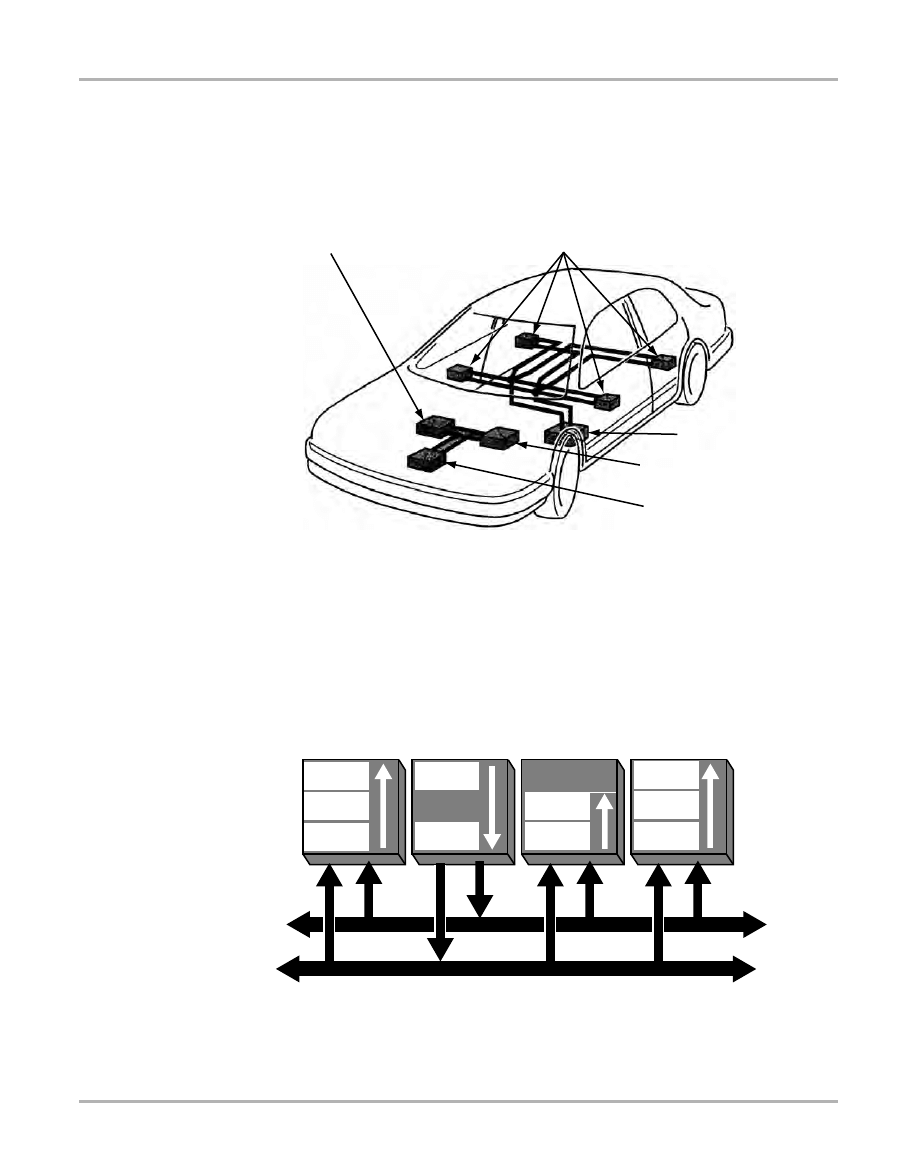
89
Testing
Testing CAN Data Bus Systems
5.9 Testing CAN Data Bus Systems
Late 2001 and early 2002 models started using a CAN (Controller Area Network) data bus, which
affects diagnostics and how and when the scan tool is used. The CAN data bus ensures that the
electronics in the vehicle still remain manageable and do not take up too much space. CAN means
that control units are networked and interchange data.
1— ABS control module
2— Door control modules
3— Central control module
4— Transmission control module
5— electronic control module
Figure 5-1
CAN control unit network
The CAN data bus is made up of a controller, a transceiver, two data bus terminals, and two data
bus lines. Apart from the data bus lines, the components are located in the control units.
Figure 5-2
CAN bus data transfer process
1
2
3
4
5
Accept
Data
Check
Data
Receive
Data
Accept
Data
Check
Data
Receive
Data
Check
Data
Receive
Data
Provide
Data
Send
Data
Data Bus Line
Data Bus Line

90
Testing
Testing CAN Data Bus Systems
The CAN controller receives the transfer data from the microcomputer integrated in the control
unit. The CAN controller processes this data and relays it to the CAN transceiver. Likewise, the
CAN controller receives data from the CAN transceiver, processes it and relays it to the
microcomputer integrated in the control unit.
The data bus does not have a designated receiver. Data is sent over the data bus and is generally
received and evaluated by all subscribers (modules on the data bus).
5.9.1 Sources of Interference
Components which produce sparks or in which electric circuits are open or closed during
operation can be sources of interference. Other sources of interference include mobile telephones
and transmitter stations, or any other object which produces electromagnetic waves.
Electromagnetic waves can affect or corrupt data transfer.
To prevent interference with the data transfer, the two data bus lines are twisted together so that
the voltage on both lines is opposed. That means that if a voltage of approximately 0 Volts is
applied to the one data bus line, then a voltage of approximately 5 Volts is applied to the other line
and vice versa. As a result, the total voltage remains constant at all times and the electromagnetic
field effects of the two data bus lines cancel each other out. The data bus line is protected against
received interference and is virtually neutral in sending interference.
5.9.2 Powertrain CAN Bus
The CAN data bus links the following:
•
The Motronic Engine management control unit
•
The ABS/EDL control unit
•
The automatic gearbox control unit
The data bus operates at a speed of 500 kbit/s (500,000 bits per second). This means that it lies
in a speed range (high speed) from 125 to 1000 kbit/s. A data protocol transfer takes about 0.25
milliseconds. Each control unit tries to send its data at intervals of 7–20 milliseconds.
If more than one control unit wants to send its data protocol simultaneously, the system must
decide which control unit comes first. For safety reasons, the data protocol supplied by the ABS/
EDL control unit is more important than the data protocol supplied by the engine control unit or
automatic gearbox unit, so ABS/EDL data takes priority and is sent first. Table 5-16 demonstrates
the order of priority of data on the CAN bus line.
Table 5-16
Order of CAN bus information priorities in the drive train
Priority
Control Unit
Example
1
ABS/EDL
Request for Traction Control System (TCS)
2
ECU, data protocol 1
Engine speed; throttle valve position; kickdown
3
ECU, data protocol 2
Coolant temperature; road speed
4
TCM
Gearshift; gearbox in emergency mode; selector lever position

91
Testing
Testing CAN Data Bus Systems
NOTE:
i
All control units which interchange information must be regarded as an integrated system during
self-diagnosis and troubleshooting. This means data displayed at one control unit may actually be
shared from another control unit on the CAN Bus. Codes set in one control unit will often set codes
in other control units which share the data bus. Always clear codes in each control unit and
monitor in which control unit the codes return.
5.9.3 CAN Data Bus in the Convenience System
The following functions of the convenience system transfer data:
•
Central locking
•
Electric windows
•
Switch illumination
•
Electrically adjustable and heated door mirrors
•
Self-diagnosis
In the convenience system, the CAN data bus currently connects the control units of the
convenience system. These are a central electronic unit (09) and two or four door Central door
Lock (35) control units.
The lines of the control units converge at one point in a star pattern. The advantage: if one of the
control units fails, the other control units are still able to send their data protocols. Each control unit
tries to send its data at intervals of 20 milliseconds.
The following list describes how the information in the convenience system is prioritized:
1.
Central control unit
2.
Control unit on driver’s side
3.
Control unit on front passenger’s side
4.
Control unit on rear left
5.
Control unit on rear right
Since the data in the comfort system can be transferred at a relatively low speed, it is possible to
use a transceiver with a lower power output. The advantage is that it is possible to change over to
single-wire mode if a data bus line fails. The data can still be transferred.

92
Chapter 6
Data Parameters
The following chapters provide definitions and operating ranges for the Volkswagen and Audi
vehicle data stream parameters.
The ECM provides two basic kinds of parameters: digital (or discrete) and analog:
•
Digital (discrete) parameters are those that can be in only one of two states, such as on or
off, open or closed, high or low, rich or lean, and yes or no. Switches, relays, and solenoids are
examples of devices that provide discrete parameters on the control module data list.
•
Analog parameters are displayed as a measured value in the appropriate units. Voltage,
pressure, temperature, time, and speed parameters are examples of analog values. The scan
tool displays them as numbers that vary through a range of values in units, such as pounds
per square inch (psi), kilopascal (kPa), degrees Celsius (°C), degrees Fahrenheit (°F),
kilometers per hour (KPH), or miles per hour (MPH).
The scan tool displays some data parameters in numbers that range from 0 to 100, 0 to 255, or 0
to 1800. These ranges are used because it is the range that the control module transmits for a
given parameter. However, many parameter readings never reach the highest possible number.
The maximum range of a parameter often varies by year, model, and engine. On these
applications, the word “variable” appears in the range heading. However, typical sampled values
observed under actual test conditions are in the parameter description when available.
Parameters may also be identified as input signals or output commands.
•
Input or feedback parameters are signals from various sensors and switches to the control
module. They may display as analog or discrete values, depending upon the input device.
•
Output parameters are commands that the control module transmits to various actuators,
such as solenoids and fuel injectors. They are displayed as discrete (ON/OFF) parameters,
analog values or as a pulse-width modulated (PWM) signal.
In the following section, parameters are presented as they appear on the scan tool screen. Most
parameter descriptions are in alphabetical order, but there are exceptions. Often, the same
parameter goes by a similar, but different, name when used on more than one model, engine, or
control system. In these instances, all of the applicable parameter names, as displayed on the
scan tool, are listed in alphabetical order before the description.
To find the description of a parameter, locate it in the alphabetical index, then go to the indicated
page. Parameters are listed in the index as they appear on the scan tool screen.
The data parameter descriptions in this manual were created from a combination of sources. For
most parameters, some basic information was provided by the vehicle manufacturers, then
expanded through research and field testing. Parameter definitions and ranges may expand as
more test results become available. For some parameters, no information is currently available.
The scan tool may display names for some data parameters that differ from names displayed by
a factory tool and other scan tools.
Always use a meter or lab scope, to further validate the displayed values. If data is corrupted on
multiple parameters, do not assume that the control module may be faulty. This corrupt data may
be caused by improper communication between the scan tool and the control module controller.

93
Data Parameters
Alphabetical Parameter List
6.1 Alphabetical Parameter List

94
Data Parameters
Alphabetical Parameter List
B
C

95
Data Parameters
Alphabetical Parameter List
E

96
Data Parameters
Alphabetical Parameter List
F
G
H
I

97
Data Parameters
Alphabetical Parameter List

98
Data Parameters
Alphabetical Parameter List
K
L

99
Data Parameters
Alphabetical Parameter List

100
Data Parameters
Alphabetical Parameter List

101
Data Parameters
Alphabetical Parameter List
O

102
Data Parameters
Alphabetical Parameter List
P
R

103
Data Parameters
Alphabetical Parameter List
T

104
Data Parameters
Alphabetical Parameter List
U
V
W

105
Data Parameters
Gas Engine Parameters
6.2 Gas Engine Parameters
A/C COMP SW OFF BY ENG-ECU _________________________________ (range: YES/NO)
Indicates an ECM-controlled switch which disables the operation of the A/C if a fault is detected
by the ECM. If the ECM has switched the A/C off, the reading will be YES.
A/C COMPRESSOR _____________________________________________ (range: ON/OFF)
Indicates a feedback signal from the A/C compressor clutch or relay. When the display reads ON,
the clutch is engaged, when it reads OFF, the clutch is disengaged.
A/C COMPRESSOR OFF)
A/C COMPRESSOR ON __________________________________________ (range: YES/NO)
Indicates whether the A/C compressor is running.
A/C MODE___________________________________________________(range: HIGH/LOW)
Indicates whether the A/C system is set in the HIGH or LOW mode.
A/C READINESS _______________________________________________ (range: YES/NO)
Indicates if the A/C is ready to be used. If A/C is fitted and no defects are found in the system, the
reading will be YES. If the vehicle does not have A/C fitted or a fault in the system or wiring is
found, the reading will be NO.
A/C SWITCH ___________________________________________________ (range: ON/OFF)
Informs the ECM whether the A/C switch is set at ON/OFF or HIGH/LOW.
ACCELERATION ENRICHMENT ___________________________________ (range: YES/NO)
Indicates whether the ECM provides a richer mixture during acceleration by momentarily
increasing injector pulse width. It should read YES when the ECM is enriching the mixture during
acceleration. Injector pulse width should also increase at the same time. It should read NO under
all other conditions.
ACCEL.PEDAL POSITION SNS 1(%)
ACCEL.PEDAL POSITION SNS 2(%) ___________________________ (range: not available)
Indicates the position of the acceleration pedal in percentage. A V-type Engine uses 2 sensors,
which are designated by the 1 and 2 in the parameter name.
ACTUAL ADAPTATION POSITION(V)___________________________ (range: not available)
Indicates the adaptive position of the EGR valve calculated by the ECM in voltage.
ADAPTATION ABORTED(BATTERY <8V) ___________________________ (range: YES/NO)
Indicates whether the ECM has recognized a battery voltage less than 8V. If the reading is NO,
then Adaptation (adaptive learn) can take place. If the reading is YES, then the ECM will not
relearn any values.
ADAPTATION ERROR ___________________________________________ (range: YES/NO)
Indicates whether an error in the throttle adjustment is detected. It reads YES if a fault is detected,
check for trouble codes. It reads NO at all other times.
ADAPTATION REQUIRED ________________________________________ (range: YES/NO)
Indicates whether the Idle Stabilizing Control (ISC) system is being operated outside of the
learned values. It reads YES only when an Adaptation is required to inform the ECM of the new
ISC position.
ADAPTATION RUNNING _________________________________________ (range: YES/NO)
Indicates whether the ECM is updating the throttle position sensors idle and full open positions. It
reads YES during adaptation, NO at all other times.

106
Data Parameters
Gas Engine Parameters
ADAPTATION STATUS_______________________________ (range: RUNNING/OK/ERROR)
Indicates whether the ECM is learning a position for the throttle valve, for example: under normal
conditions the reading should be OK.
RUNNING will be displayed for a short time as the ECM learns the new values while in Basic
Setting mode. If ERROR is displayed, then a fault in the learning processes has occurred.
ADP ENG SPEED SENSOR(CROWN GEAR) __________________ (range: I/O or RUNNING)
Indicates the operation of the crankshaft sensor and the segmented gear fitted to the crankshaft
and adapts the ECM for ignition misfires. The crown gear is the segmented disk fitted on the
crankshaft and the engine speed sensor (Hall-effect sensor) takes its signal from the teeth on this
gear. If the display reads RUNNING, then the sender/gear check has not yet been completed and
the misfire detection is restricted until the adaptation is completed. The sender/gear check can
only be performed during overrun conditions.
ADP IDLING STABILIZATION(kg/h) ____________________________ (range: not available)
Indicates the learning value of the idle control system. The reading is the volume of air the ECM is
commanding in kilograms per hour.
ADP STOPPED(TIME EXCEEDED) _________________________________ (range: YES/NO)
Indicates whether the adaptation process was stopped because the maximum time allowed was
exceeded. The normal reading is NO, Yes indicates an adaptation problem.
ADP THROTTLE VALVE ADJUSTER ___________________________ (range: not available)
Indicates the current throttle adjuster adaptation mode and can display ADP, (running) ADP OK,
or ADP ERROR.
ADP VALUE AIR MASS IDLE(%)_______________________________ (range: not available)
Indicates the amount of extra air mass required to keep the engine idle speed correct when a
change in load occurs, such as when the A/C or the rear heater is switched on.
ADP VALUE CANP SYSTEM __________________________________ (range: not available)
Indicates the learning value of the canister purge system. It displays the duty cycle the ECM is
commanding.
ADP VALUE CANP VALVE
ADP VALUE CANP VALVE 1(%) _______________________________ (range: not available)
Indicates the learning value of the canister purge system. It displays the duty cycle the ECM has
learned.
ADP VALUE ISC ____________________________________________ (range: not available)
Indicates the learning value of the idle control system. It displays the duty cycle the ECM is
commanding.
ADP VALUE MIXTURE(BANK1)(%)
ADP VALUE MIXTURE(BANK2)(%) ____________________________ (range: not available)
Indicates the operation and Short-term correction of the fuel delivery for cylinders 1 to 3 (Bank 1)
and cylinders 4 to 6 (Bank 2). It shows whether the ECM is commanding a rich or lean mixture.
A number above 0% indicates that the ECM has commanded a temporary rich mixture correction.
A number below 0% indicates that the ECM has commanded a temporary lean mixture correction.
These Short-term correction numbers are also used by the ECM to learn a fuel correction pattern
or trend and are stored in the learned mixture or lambda values. Fuel correction parameters
operate only in closed loop. In open loop, the number changes to a fixed value.

107
Data Parameters
Gas Engine Parameters
ADP VALUE MIXTURE(BANK1)
ADP VALUE MIXTURE(BANK2) __________________________________ (range: 0.0 to 1.9)
Indicates the operation and Short-term correction of the fuel delivery for cylinders 1 to 4 (Bank 1)
and for cylinders 5 to 8 (Bank 2). It shows whether the ECM is commanding a rich or lean mixture.
The number theoretically can range from 0.0 to 1.9 with 1.0 as the midpoint. A number above 1.0
indicates that the ECM has commanded a temporary rich mixture correction. A number below 1.0
indicates that the ECM has commanded a temporary lean mixture correction. Fuel correction
parameters operate only in closed loop. In open loop, the number changes to a fixed value.
AIR DIVERT VALVE _____________________________________________ (range: ON/OFF)
Indicates the state of the dual path intake manifold used on the 2.8 5V V6. There are two sets of
intake runners of different lengths. At lower engine speeds the length of the intake manifold is
lengthened with smaller diameter runners to produce a ram effect (increased air velocity). At
higher RPM, the intake manifold is shortened with larger diameter runners to reduce restriction to
faster moving air. Should read ON (ECM command) at 4500 RPM.
An actuator or rotary servo changes intake manifold position from low to high or high to low. At
4500 RPM after the Intake Manifold change over valve receives a signal from the ECM, it supplies
vacuum to the servo which in turn moves the rotary valve to engage the high speed intake runners.
When engine RPM drops, the change over valve shuts off vacuum to the servo (low speed intake
runners) and vents trapped vacuum.
AIR MASS IDLE(g/s) ________________________________________ (range: not available)
Indicates the amount of alteration required to maintain idle speed when there is a change in load
conditions at idle, such as when the heated rear window is switched on. Once the ECM has
learned the new value, the figure should return to the mean setting (0).
ALTERNATOR DEFECT __________________________________________ (range: YES/NO)
Indicates whether the ECM has recognized a charging voltage. The reading is YES when the ECM
is allowing adaptation (adaptive learn). If the reading is NO, the ECM will not relearn any
adaptation values.
ALTERNATOR LOAD(%) _____________________________________ (range: not available)
Indicates the current alternator load.
ALTITUDE CORRECTION FACTOR
ALTITUDE CORRECTION FACTOR(%)__________________________ (range: not available)
Indicates the correction factor for altitude, which is applied to air intake and lambda values when
driving in mountainous terrain. This is an ECM-calculated value that compares air mass and
throttle angle, and is greatly influenced by intake air temperature.
AMBIENT TEMPERATURE(°C/°F) ______________________________ (range: not available)
Indicates the temperature of the ambient air outside the vehicle.
AUX HEATING REQUESTED__________________________________ (range: not available)
Indicates if Auxiliary Heat is requested or not.
BAROMETRIC PRESSURE(mbar) _____________________________ (range: not available)
Indicates barometric pressure, which is provided by the barometric pressure (BARO) sensor, in
millibars. The reading should be high when barometric pressure is near atmospheric pressure at
sea level, and drop as barometric pressure drops.

108
Data Parameters
Gas Engine Parameters
The ECM uses the BARO sensor to calculate manifold vacuum and true absolute pressure. Some
systems do not have a BARO sensor, but the ECM provides a BARO reading by sampling the
MAP sensor reading with the key on and engine off just before cranking.
BASE THR POS(IDLE SW CLSD)(°) ____________________________ (range: not available)
Indicates throttle opening in degrees based on the Throttle Position Sensor low range
potentiometer. This is one of two potentiometers incorporated into one (throttle position) TP
sensor. The signal is for the whole range (from idle to full throttle).
BASE VALUE THROTTLE ADJUSTER __________________________ (range: not available)
Indicates the stored base value for the throttle value potentiometer position when throttle valve is
fully closed. The value is determined when base settings are activated with the throttle closed.
BASE VALUE TPS
BASE VALUE TPS(V) ________________________________________ (range: not available)
Indicates the voltage from throttle position (TP) sensor low range potentiometer. This is one from
a set of two potentiometers incorporated into one TP sensor. The signal is for the whole range
(from idle to full throttle).
BATTERY(V) _______________________________________________ (range: not available)
Indicates vehicle battery voltage. The engine control system has no specific sensor to measure
battery voltage, but some ECMs calculate this parameter from a sensing circuit across the supply
voltage circuit. The reading should be close to normal charging system regulated voltage with the
engine running. This is typically 13.5 to 14.5V at idle. Check the reading against actual voltage
measured at the battery or alternator. Check vehicle specifications for exact values.
The battery voltage value is used principally for ECM self-diagnostics. Some ECM functions will
be modified if voltage falls too low or rises too high. For example, if voltage drops below minimum
value, the ECM will try to recharge the battery by running the engine at a higher idle speed. This
may affect the idle speed control, fuel metering and ignition timing parameters.
BATTERY VOLTAGE TOO LOW ___________________________________ (range: YES/NO)
Indicates whether the ECM has recognized a battery voltage that is too low for reliable operation.
If the reading is NO, then Adaptation (adaptive learn) can take place. If the reading is YES, then
the ECM will not relearn any values.
BOOST PRESSURE(ACTUAL)(mbar)___________________________ (range: not available)
Indicates the current pressure in the intake manifold. The value is in millibar and will be an
absolute pressure.
BOOST PRESSURE(DESIRED)(mbar) __________________________ (range: not available)
Indicates the desired intake manifold pressure under present operating conditions. The value is in
millibar and will be an absolute pressure.
BOOST PRESSURE(mbar) ___________________________________ (range: not available)
Indicates the pressure in the intake manifold under current operating conditions. The value is in
millibar and will be an absolute pressure.
BRAKE PEDAL PRESSED _______________________________________ (range: YES/NO)
Indicates whether the ECM has detected that the brake pedal has been pressed.
BRAKE PEDAL SWITCH ___________________________________(range: OPEN/CLOSED)
Indicates whether the ECM has detected that the brake pedal switch is closed or open.
CAM ADJUSTER MODE ______________________________ (range: ACTIVE/NOT ACTIVE)
Indicates whether the ECM has activated camshaft timing adjustments.

109
Data Parameters
Gas Engine Parameters
CAMSHAFT ADJUSTER ______________________________ (range: ACTIVE/NOT ACTIVE)
Indicates whether the ECM has activated camshaft timing adjustments.
CAMSHAFT ADJUSTER(ACTIVE)(°)
CAMSHAFT ADVANCE(°) ____________________________________ (range: not available)
Indicates the amount of camshaft adjustment commanded by the ECM in degrees.
CAMSHAFT PHASING ___________________________________________ (range: YES/NO)
Indicates whether the ECM has activated the camshaft timing adjustments.
CAMSHAFT POSITION(BANK 1)(°)
CAMSHAFT POSITION(BANK 2)(°)_____________________________ (range: not available)
Indicates the amount of camshaft adjustment commanded by the ECM for the intake camshaft on
cylinders 1 to 3 (Bank 1) or cylinders 4 to 6 (Bank 2) from its base position.
CANISTER PURGE MODE_____________________________ (range: ACTIVE/NOT ACTIVE)
Indicates the operating mode of the canister purge valve.
CANP CHARGE(%) ___________________________________________ (range: 0 to 100%)
Indicates the percentage of canister purge flow. The duty cycle solenoids in these systems are
turned on to activate purging and turned off to block purging. A reading of 0 indicates that the
solenoid is fully de-energized to cut off purging. A reading of 100 indicates that the solenoid is fully
energized to allow maximum purging.
CANP FLUSH ________________________________________________ (range: 0 to 100%)
Indicates the percentage of canister purge flushed from the charcoal canister back into the engine
for re-burn. A reading of 0 indicates the solenoid is fully de-energized to cut off purging. A reading
of 100 indicates the solenoid is fully energized to allow maximum purging.
CANP SYSTEM ACTIVE _________________________________________ (range: YES/NO)
Indicates the status of the canister purge valve, it reads YES when the canister purge valve
(CANP) is active (purging).
CANP VALVE CLOSED __________________________________________ (range: YES/NO)
Indicates the status of the canister purge valve, it reads YES when the canister purge valve
(CANP) is closed (not purging).
CANP VALVE ON CHARGE _______________________________________ (range: YES/NO)
Indicates the status of the canister purge valve, it reads YES when the canister purge valve
(CANP) is in check mode. In check mode, the ECM calculates the fuel content of the fumes
coming from the canister by measuring the effect the fumes have on the lambda signal.
CANP VALVE ON MIN MODE _____________________________________ (range: YES/NO)
Indicates the status of the canister purge valve, it reads YES when the canister purge valve
(CANP) is at a minimum pulse width in order to stop sudden mixture changes and improve
driveability.
CANP VALVE ON NORMAL MODE _________________________________ (range: YES/NO)
Indicates the status of the canister purge valve, it reads YES when the canister purge valve
(CANP) is operating normally.
CAT TEMPERATURE>300°C __________________________________ (range: not available)
Indicates whether catalytic converter (CAT) temperature is above 300°C (572°F).
CATALYST TEMPERATURE(°C/F) _____________________________ (range: not available)
Indicates catalytic converter (CAT) temperature.

110
Data Parameters
Gas Engine Parameters
CATALYST EFFICIENCY(%) __________________________________ (range: not available)
Indicates the efficiency of the catalytic converter (CAT) based on O2S signals.
CHANGE OVER TO CHARGE MODE CANP _________________________ (range: YES/NO)
Indicates the status of the canister purge valve, it reads YES when the canister purge valve
(CANP) is in charge mode.
CHANGE OVER TO CLOSE MODE CANP ___________________________ (range: YES/NO)
Indicates the status of the canister purge valve, it reads YES when the canister purge valve
(CANP) is closed.
CHANGE OVER TO MIN MODE CANP ______________________________ (range: YES/NO)
Indicates the status of the canister purge valve, it reads YES when the canister purge valve
(CANP) is at a minimum pulse width in order to stop sudden mixture changes and improve
driveability.
CLUTCH PEDAL PRESSED ______________________________________ (range: YES/NO)
Indicates clutch pedal status, it reads YES when the ECM detects the clutch pedal is pressed.
CLUTCH PEDAL SWITCH __________________________________(range: OPEN/CLOSED)
Indicates the current state of the clutch pedal switch.
CODING FOR SYNCRO(4WD)_____________________________________ (range: YES/NO)
Indicates whether the ECM is coded for 4WD.
COMBINED HALL & ENG SPEED SIGN _________________________ (range: not available)
Indicates the number of teeth on the crankshaft sender wheel until the hall sensor on the camshaft
switches. The ECM uses this to determine the relative positions of crank and cam.
CONTROL VALUE MIXTURE(%)
CTRL VALUE MIXTURE(BANK 1)(%)
CTRL VALUE MIXTURE(BANK 2)(%) ___________________________ (range: not available)
Indicates the operation and Short-term correction of the fuel delivery for the stated cylinders. The
reading shows whether the ECM is commanding a rich or lean mixture.
A number above 0% indicates that the ECM has commanded a temporary rich mixture correction.
A number below 0% indicates that the ECM has commanded a temporary lean mixture correction.
These Short-term correction numbers are also used by the ECM to learn a fuel correction pattern
or trend and are stored in the learned mixture or lambda values. Fuel correction parameters
operate only in closed loop. In open loop, the number changes to a fixed value.
COOLANT TEMPERATURE >80°C _________________________________ (range: YES/NO)
Indicates whether the engine coolant temperature is above 80°C (176°F). It is used during some
adaptive learning processes.
CRUISE CTRL ENABLED ________________________________________ (range: ON/OFF)
Indicates the current state of the main cruise control switch.
CRUISE CTRL STATUS _______________________________ (range: ACTIVE/NOT ACTIVE)
Indicates the current state of the main cruise control switch.
CTRL VALUE IDLE AIR MASS(g/s)_____________________________ (range: not available)
Indicates the amount of air that bypasses the throttle at idle and thus controls the idle speed. The
motor that drives the IAC valve returns a value of 0 to 255 to the ECM. The ECM then converts this
value into an airflow value in grams per second.

111
Data Parameters
Gas Engine Parameters
CTRL VALUE MIXTURE/O2 ___________________________________ (range: not available)
Indicates the operation and Short-term correction of the fuel delivery. The reading shows whether
the ECM is commanding a rich or lean mixture.
The number theoretically can range from 0.00 to 1.99 with 1.00 as the midpoint, but in practice the
number only ranges from 0.9 to 1.1. A number above 1.0 indicates that the ECM has commanded
a temporary rich mixture correction. A number below 1.0 indicates that the ECM has commanded
a temporary lean mixture correction.
These Short-term correction numbers are also used by the ECM to learn a fuel correction pattern
or trend and are stored in the learned mixture or lambda values. Fuel correction parameters
operate only in closed loop. In open loop, the number changes to a fixed value.
CTRL VALUE MIXTURE/O2(%) ________________________________ (range: not available)
Indicates the operation and Short-term correction of the fuel delivery. The reading shows whether
the ECM is commanding a rich or lean mixture.
A number above 0% indicates that the ECM has commanded a temporary rich mixture correction.
A number below 0% indicates that the ECM has commanded a temporary lean mixture correction.
These Short-term correction numbers are also used by the ECM to learn a fuel correction pattern
or trend and are stored in the learned mixture or lambda values. Fuel correction parameters
operate only in closed loop. In open loop, the number changes to a fixed value.
CURRENT CONSUMPTION IAC(A)_____________________________ (range: not available)
Indicates the amount of current used by the IAC (Idle Air Control) valve as amperes.
CURRENT CTRL FACTOR IAC ________________________________ (range: not available)
Indicates the amount of current used by the IAC (Idle Air Control) valve as a percentage.
CURRENT CTRL IAC(%) _____________________________________ (range: not available)
Indicates the control factor regulating the current to the IAC valve as a percentage.
CYLINDER 1 RECOGNIZED ______________________________________ (range: YES/NO)
Indicates whether the ECM has detected cylinder number 1 TDC.
DECEL ENLEAN____________________________________________ (range: not available)
Indicates whether the ECM is providing a lean air/fuel mixture during deceleration.
DECELERATE POSITION ________________________________________ (range: YES/NO)
Indicates whether the ECM determines the current engine operating condition as deceleration.
DECELERATION ENLEANMENT ______________________________ (range: not available)
Indicates whether the ECM is providing a lean air/fuel mixture due to deceleration.
DIAGNOSE LEARN VALUE O2(BK1)IDLE
DIAGNOSE LEARN VALUE O2(BK1)P/T2
DIAGNOSE LEARN VALUE O2(BK1)P/T3
DIAGNOSE LEARN VALUE O2(BK1)P/T4
DIAGNOSE LEARN VALUE O2(BK2)IDLE
DIAGNOSE LEARN VALUE O2(BK2)P/T2
DIAGNOSE LEARN VALUE O2(BK2)P/T3
DIAGNOSE LEARN VALUE O2(BK2)P/T4 ___________________________ (range: YES/NO)
Indicates whether the relearn operation for the stated cylinders and engine/throttle load conditions
was successful.

112
Data Parameters
Gas Engine Parameters
DUTY CYCLE CANP VALVE
DUTY CYCLE CANP VALVE(%) _______________________________ (range: not available)
Indicates the percentage of canister purge flow. The duty cycle solenoids in these systems are
turned on to activate purging and turned off to block purging. A reading of 0% indicates that the
solenoid is fully de-energized to cut off purging. A reading of 100% indicates that the solenoid is
fully energized to allow maximum purging.
DUTY CYCLE EGR-VALVE(%)_________________________________ (range: not available)
Indicates the duty cycle of the Exhaust Gas Recirculating (EGR) valve. Exhaust gasses can be
added to the intake air (to cool combustion temperatures thus reducing the formation of NOx).
EGR valve open/close rate depends on operating conditions of the engine.
DUTY CYCLE FAN CTRL VALVE(%)____________________________ (range: not available)
Indicates the duty-cycle of the electric ventilator. A lower percentage means the ventilator is
blowing lightly.
DUTY CYCLE IAC(%)________________________________________ (range: not available)
Indicates the duty cycle of the IAC valve.
DUTY CYCLE ISC(%) ________________________________________ (range: not available)
Indicates the duty cycle of the throttle valve positioner, which regulates the throttle stop position,
thus controlling idle speed.
DUTY CYCLE THR ADJUSTER(%) _____________________________ (range: not available)
Indicates the duty cycle of the throttle adjuster valve.
DUTY CYCLE WASTE GATE VALVE(%) _________________________ (range: not available)
Indicates the duty cycle of the turbo waste gate actuator valve. This action governs the turbo
output (manifold) pressure.
EGR-SYSTEM_______________________________________ (range: ACTIVE/NOT ACTIVE)
Indicates whether the EGR system is active or not.
EGR-TEMPERATURE(°C/°F) __________________________________ (range: not available)
Indicates EGR system temperature based on a feedback signal from a thermistor installed in the
EGR passage.
ENGINE LOAD(%) __________________________________________ (range: not available)
Indicates the ECM calculated relative engine load based on engine speed (RPM), number of
cylinders, and manifold airflow. High readings indicate a heavy load; low readings, a light load.
ENGINE LOAD(ms) _________________________________________ (range: not available)
Indicates the relative engine load based on a processed signal that comes from the Throttle
Position Sensor and/or the Manifold Air Flow sensor and/or the Manifold Air Pressure sensor and/
or the Intake Air Temperature sensor. The Engine Load has still to be corrected with all lambda
factors. View this in conjunction with the injection period where Engine Load is the theoretical
Injection time and the injection period is the corrected actual value.
ENGINE LOAD(V)___________________________________________ (range: not available)
Indicates the ECM calculated relative engine load as voltage based on engine speed (RPM),
number of cylinders, and manifold airflow.
ENGINE LOAD(ACTUAL)(%)__________________________________ (range: not available)
Indicates the ECM calculated actual engine load based on engine speed (RPM), number of
cylinders, and manifold airflow. High readings indicate a heavy load; low readings, a light load.

113
Data Parameters
Gas Engine Parameters
ENGINE LOAD(ACTUAL)(ms)_________________________________ (range: not available)
Indicates the actual engine load based on a processed signal that comes from the Throttle
Position Sensor and/or the Manifold Air Flow sensor and/or the Manifold Air Pressure sensor and/
or the Intake Air Temperature sensor. The load has been corrected with all factors.
ENGINE LOAD(ACTUAL)(Nm) ________________________________ (range: not available)
Indicates the ECM calculated actual engine load based on engine speed (RPM), number of
cylinders, and manifold airflow as newton meters (Nm).
ENGINE LOAD(AFTER CORR)(ms) ____________________________ (range: not available)
Indicates the corrected engine load based on a processed signal that comes from the Throttle
Position Sensor and/or the Manifold Air Flow sensor and/or the Manifold Air Pressure sensor and/
or the Intake Air Temperature sensor. The load has been corrected with all factors.
ENGINE LOAD(BEFORE CORR)(ms) ___________________________ (range: not available)
Indicates the uncorrected engine load based on a processed signal that comes from the Throttle
Position Sensor and/or the Manifold Air Flow sensor and/or the Manifold Air Pressure sensor and/
or the Intake Air Temperature sensor. The load has still to be corrected with all lambda factors.
ENGINE LOAD AFTER REDUC(ms) ____________________________ (range: not available)
Indicates the engine load based on a processed signal that comes from the Throttle Position
Sensor and/or the Manifold Air Flow sensor and/or the Manifold Air Pressure sensor and/or the
Intake Air Temperature sensor. The load has been corrected with knock control factors.
ENGINE SPEED(RPM) _______________________________________ (range: not available)
Indicates whether the ECM is receiving engine speed information from the engine speed sensor,
then passing this information on to the TCM.
Signal utilization: The engine speed signal is one of the most important input signals and is
required for calculation of the shift points.
ENGINE SPEED <760 RPM
ENGINE SPEED <2000 RPM
ENGINE SPEED <2300 RPM
ENGINE SPEED <2500 RPM
ENGINE SPEED >2500 RPM
ENGINE SPEED >1800 RPM ______________________________________ (range: YES/NO)
Indicates whether the engine is running at more than (<) or less than (>) the indicated RPM. They
are used during some adaptive learning processes.
ENGINE SPEED(ACTUAL)(RPM)
Indicates the ECM calculated engine speed based on reference pulses from the ignition system or
a crankshaft sensor. This is the recorded actual RPM as opposed to desired RPM.
ENGINE SPEED(DESIRED)(RPM)______________________________ (range: not available)
Indicates the idle speed that the ECM is trying to maintain. If there is a large difference between
actual idle and desired RPM readings, the ECM may have reached its control limit without being
able to control the idle speed. This may be due to a basic mechanical or electrical problem with the
engine.
ENGINE SPEED(IDLE)(RPM)__________________________________ (range: not available)
Indicates the actual recorded idle RPM as opposed to desired RPM.
ENGINE SPEED SIGNAL RECOGNIZED ____________________________ (range: YES/NO)
Indicates whether the ECM has determined that the engine is running. The reading should be YES
with the engine running, this value is used during some adaptive learning processes.

114
Data Parameters
Gas Engine Parameters
EXHAUST GAS TEMPERATURE(°C/°F) _________________________ (range: not available)
Indicates the exhaust-gas temperature.
FUEL COOLING(%) _________________________________________ (range: not available)
Indicates the percentage that the fuel is cooled.
FUEL CUT OFF
FUEL CUT-OFF VALVE ACTIVE ___________________________________ (range: YES/NO)
Indicates the status of the ECM command to cut off to the injectors during engine overrun.
FUEL HEAT(l/h) ____________________________________________ (range: not available)
Indicates the amount of fuel that is used by the external heater.
FUEL LOW ________________________________________________ (range: not available)
Indicates whether the fuel level is low.
FULL LOAD DETECTED
FULL LOAD ___________________________________________________ (range: YES/NO)
Indicates whether the engine is currently operating at full load. The reading is YES at full load, this
value is used during some adaptive learning processes.
FULL LOAD SWITCH ______________________________________(range: OPEN/CLOSED)
Indicates the ECM output to the TP sensor full load switch.
HALL-SENSOR(°)
Indicates the position of the Hall Sensor offset against the zero adjustment in crankshaft angle
degrees.
IAC INTEGRATOR __________________________________________ (range: not available)
Indicates the working zero range of the idle air control (IAC). It represents the point that the ECM
regards as IAC set to 0 (no adjustment required). The number can range from 0 to 255 with 128
as the midpoint. A number above 128 indicates that the ECM has learned to reduce the idle. A
number below 128 indicates that the ECM has learned to increase the idle.
IDLE AIR CORRECTION(g/s) _________________________________ (range: not available)
Indicates the correction factor of the idle control system. The value is the amount of airflow
correction the ECM is commanding.
IDLE AIR CTRL(%) __________________________________________ (range: not available)
Indicates the duty cycle of the idle air control valve, which regulates the throttle stop position, thus
controlling idle speed.
IDLE AIR MASS(g/s) ________________________________________ (range: not available)
Indicates the amount of air being drawn into the engine at idle. Most port fuel injection engines
have an airflow sensor to measure the mass or weight of air entering the engine. The airflow
sensor delivers a signal that indicates the mass airflow in grams per second at any given instant.
The ECM uses the signal from the airflow sensor and other sensors to determine the air/fuel ratio
needed by the engine and the amount of fuel to be injected.
IDLE SPEED(ACTUAL)(RPM) _________________________________ (range: not available)
Indicates the actual engine idle speed recorded by the ECM, as opposed to desired RPM.
IDLE SPEED(DESIRED)(RPM) ________________________________ (range: not available)
Indicates the engine idle speed the ECM is trying to maintain, as opposed to the actual RPM.

115
Data Parameters
Gas Engine Parameters
IDLE SPEED CTRL VALVE
IDLE SPEED CTRL VALVE(%)_________________________________ (range: not available)
Indicates the amount of air that bypasses the throttle at idle. The motor that drives the IAC valve
returns a value of 0 to 255 to the ECM. The ECM then converts this value into an airflow value as
a percentage of the total airflow.
IDLE SPEED SWITCH _____________________________________(range: OPEN/CLOSED)
Indicates the ECM has detected idle switch state. It is used in conjunction with other parameters
when the ECM is applying learned idle values.
IDLE SPEED SWITCH CLOSED ___________________________________ (range: YES/NO)
Indicates whether the ECM has detected that the idle switch is closed. It is used in conjunction
with other parameters when the ECM is applying learned idle values.
IDLE SPEED SWITCH OPEN______________________________________ (range: YES/NO)
Indicates whether the ECM has detected that the idle switch is open. It is used in conjunction with
other parameters when the ECM is applying learned idle values.
IGN ADV W KNOCK & ISC(AV)(°) ______________________________ (range: not available)
Indicates the average amount of ignition advance actually applied to the engine after any
retardation by the knock sensor or idle speed control has been removed.
IGN RTD BY A/T-ECU(°) _____________________________________ (range: not available)
Indicates the amount of ignition advance removed by the ECM when the automatic transmission
commands it. Timing is retarded from the optimum advance for the existing speed and load.
IGN RTD BY DIGITAL ISC(°) __________________________________ (range: not available)
Indicates the amount of ignition advance removed by the ECM when the digital idle speed control
(ISC) commands it. Timing is retarded from the optimum advance for the existing speed and load.
IGN RTD BY KNOCK(°)
IGN RTD BY KNOCK CTRL(°)
IGN RTD BY KNOCK(ALL CYL)(°)
IGN RTD BY KNOCK CTRL(CYL 1)(°)
IGN RTD BY KNOCK CTRL(CYL 2)(°)
IGN RTD BY KNOCK CTRL(CYL 3)(°)
IGN RTD BY KNOCK CTRL(CYL 4)(°)
IGN RTD BY KNOCK CTRL(CYL 5)(°)
IGN RTD BY KNOCK CTRL(CYL 6)(°)
IGN RTD BY KNOCK CTRL(CYL 7)(°)
IGN RTD BY KNOCK CTRL(CYL 8)(°)___________________________ (range: not available)
Indicates the amount of ignition advance removed by the ECM when detonation is sensed by the
knock sensor. Timing is retarded from the optimum advance for existing speed and load.
IGN RTD BY TCS-ECU(COLD)(°) ______________________________ (range: not available)
Indicates the amount of ignition advance to be removed by the ECM using the traction control
system (only with engine cold conditions) restrictions. Timing is retarded from the optimum
advance for the existing speed and load.
IGN RTD WITH KNOCK & ISC(°) _______________________________ (range: not available)
Indicates the amount of ignition advance actually applied to the engine after any retardation by the
knock sensor or idle speed control has been removed.
IGN RTD W/O KNOCK & W/O ISC(°)____________________________ (range: not available)
Indicates the amount of ignition advance commanded by the ECM before any retardation by the
knock sensor or idle speed control has been removed.

116
Data Parameters
Gas Engine Parameters
IGNITION ADV(CALCULATED)(°) ______________________________ (range: not available)
Indicates the amount of ignition advance before other factors are removed by the ECM.
IGNITION ADV REDUCTION ___________________________ (range: ACTIVE/NOT ACTIVE)
Indicates whether the ignition timing reduction system is active or not.
IGNITION ADVANCE(°) ______________________________________ (range: not available)
Indicates the total spark advance or retard commanded by the ECM, including base timing.
IGNITION MAP _____________________________________________ (range: not available)
Indicates which ignition timing map is currently being used by the ECM. The map changeover is
initiated by the knock sensor. The 1ST TIMING MAP is the default choice (98 octane) and the 2ND
TIMING MAP retards the overall ignition timing (95 octane).
INCREASED IDLE SPEED WITH A/C ON ____________________________ (range: YES/NO)
Indicates whether the ECM has detected the A/C is active. If so, the ECM increases the idle speed
to compensate.
INCREASING RPM ______________________________________________ (range: YES/NO)
Indicates whether the ECM is increasing the idle speed because the A/C is active.
INJ QUANTITY(mm3)________________________________________ (range: not available)
Indicates the maximum quantity of fuel that has been injected under the present operating
conditions. The value is in cubic milliliters per cylinder stroke.
INJECTION TIME(ms) _______________________________________ (range: not available)
Indicates the length of time that the ECM commands the fuel injectors to turn on in milliseconds
(ms). A high reading indicates more “on time” and a richer mixture. A low reading indicates less
“on time” and a leaner mixture. There are no definite specifications for injector pulse, but the
reading should change as engine speed and load change.
INJECTION TIME(AVERAGE)(ms) _____________________________ (range: not available)
Indicates the average length of time that the ECM commands the fuel injectors to turn on in
milliseconds (ms). A high reading indicates more “on time” and a richer mixture. A low reading
indicates less “on time” and a leaner mixture. There are no definite specifications for injector
pulse, but the reading should change as engine speed and load change.
INTAKE MANIFOLD PRESSURE(%) ____________________________ (range: not available)
Indicates intake manifold vacuum as a percentage. The ECM uses the figure in calculations to
determine engine load.
INTAKE MANIFOLD PRESSURE(mbar) _________________________ (range: not available)
Indicates intake manifold vacuum as millibar. The ECM uses the figure in calculations to
determine engine load.
ISC(CTRL FACTOR) _________________________________________ (range: not available)
Indicates the idle stabilizing control factor.
ISC(POSITION) _____________________________________________ (range: not available)
Indicates the idle speed control valve position.
ISC(REACTION TO MALFUNCTION) ___________________________ (range: not available)
Indicates the influence value of a system fault on the idle speed control system.
ISC INTGRATOR____________________________________________ (range: not available)
Indicates the integrator value for the idle speed control.

117
Data Parameters
Gas Engine Parameters
ISC UNDER LOAD __________________________________________ (range: not available)
Indicates the working range of the idle speed control (ISC) when a load is applied (example, with
A/C operating). It indicates whether the ECM is commanding a faster or slower idle. The number
can range from 0 to 255 with 128 as the midpoint. A number above 128 indicates that the ECM has
commanded less air to slow the idle. A number below 128 indicates that the ECM has commanded
more air to speed up the idle.
KNOCK CTRL(°) ____________________________________________ (range: not available)
Indicates the amount of spark advance removed by the ECM when detonation is sensed by the
knock sensor. Timing is retarded from the optimum advance for existing speed and load. The
value is the amount of advance that has been taken away.
KNOCK SENSOR(CYL 1)(V)
KNOCK SENSOR(CYL 2)(V)
KNOCK SENSOR(CYL 3)(V)
KNOCK SENSOR(CYL 4)(V)
KNOCK SENSOR(CYL 5)(V)
KNOCK SENSOR(CYL 6)(V)
KNOCK SENSOR(CYL 7)(V)
KNOCK SENSOR(CYL 8)(V) __________________________________ (range: not available)
Indicates the voltage read by the ECM when detonation is sensed by the knock sensor on the
indicated cylinder.
LACK OF FUEL ____________________________________________ (range: not available)
Indicates whether or not there is a lack of fuel.
LEARN AIR MASS IDLE(g/s)__________________________________ (range: not available)
Indicates the learned value of air that bypasses the throttle at idle and thus controls the idle speed.
The motor that drives the IAC valve returns a value of 0 to 255 to the ECM. The ECM then
converts this value into an airflow value in grams per second.
LEARN AIR MASS IDLE(D)(g/s) _______________________________ (range: not available)
Indicates the learned value of air that bypasses the throttle at idle only if the transmission is in
drive. The motor that drives the IAC valve returns a value of 0 to 255 to the ECM. The ECM then
converts this value into an airflow value in grams per second.
LEARN AIR MASS IDLE(P/N)(g/s) _____________________________ (range: not available)
Indicates the learned value of air that bypasses the throttle at idle only if the transmission is in park
or neutral. The motor that drives the IAC valve returns a value of 0 to 255 to the ECM. The ECM
then converts this value into an airflow value in grams per second.
LEARN INJECTION TIME(ms)_________________________________ (range: not available)
Indicates the value in milliseconds that the ECM is using as an adaptive value for injection time
correction.

118
Data Parameters
Gas Engine Parameters
LEARN MIXT(BANK 1)(IDLE)(%)
LEARN MIXT(BANK 1)(P/T)(%)
LEARN MIXT(BANK 1)(P/T1)(%)
LEARN MIXT(BANK 1)(P/T2)(%)
LEARN MIXT(BANK 1)(P/T3)(%)
LEARN MIXT(BANK 1)(IDLE)(%)
LEARN MIXT(BANK 1)(P/T)(%)
LEARN MIXT(BANK 2)(IDLE)(%)
LEARN MIXT(BANK 2)(P/T)(%)
LEARN MIXT(BANK 2)(P/T1)(%)
LEARN MIXT(BANK 2)(P/T2)(%)
LEARN MIXT(BANK 2)(P/T3)(%)
LEARN MIXT(BANK 2)(IDLE)(%)
LEARN MIXT(BANK 2)(P/T)(%) ________________________________ (range: not available)
Indicates the operation and Long-term correction of the fuel delivery for the stated loads and
cylinders. The readings show whether the ECM is commanding a rich or lean mixture.
A number above 0% indicates that the ECM has commanded an overall rich mixture correction. A
number below 0% indicates that the ECM has commanded an overall lean mixture correction.
Fuel correction parameters operate only in closed loop. In open loop, the number changes to a
fixed value.
LEARN RANGE O2 IDLE
LEARN RANGE O2 P/T 2
LEARN RANGE O2 P/T 3
LEARN RANGE O2(BK1)IDLE
LEARN RANGE O2(BK1)P/T2
LEARN RANGE O2(BK1)P/T3
LEARN RANGE O2(BK1)P/T4
LEARN RANGE O2(BK2)IDLE
LEARN RANGE O2(BK2)P/T2
LEARN RANGE O2(BK2)P/T3
LEARN RANGE O2(BK2)P/T4 _____________________ (range: REACHED/NOT REACHED)
Indicates the state of the lambda learned range when at idle or part load section 2, 3, for cylinders
1 to 3 (Bank 1) when at idle or part load section 2, 3 or 4, and for cylinders 4 to 6 (Bank 2) when at
idle or part load section 2, 3 or 4.
NOTE:
i
On some OBD-I (1991–1995) vehicles, the displayed values for Short-term fuel trim, LEARN O2
(IDLE), LEARN O2 (P/T), or LEARN O2 (FULL), may be mislabeled as reading in percentage. In
actuality, they are reading a numeric factor of 1.0 midpoint ±0.5 (0.5 to 1.5). For 2.8L AAA engine,
the range is 0.80–1.20.
LEARN VALUE AIR MASS IDLE(%) __________________________(range: see description)
Indicates the learned value correction for idle speed based on mass airflow. The number can
range from -100% to 100% with 0% as the midpoint. A number above 0% indicates that the ECM
has commanded a overall high idle correction. A number below 0% indicates that the ECM has
commanded a overall low idle correction.
LEARN VALUE AIR MASS IDLE(g/s) _________________________(range: see description)
Indicates learned value of air that bypasses the throttle at idle and thus controls the idle speed.
The motor that drives the IAC valve returns a value of 0 to 255 to the ECM. The ECM then
converts this value into an airflow value in grams per second.

119
Data Parameters
Gas Engine Parameters
LEARN VALUE CANP SYSTEM _____________________________(range: see description)
Indicates the learned canister purge value, an internal calculating factor and can be ignored.
LEARN VALUE DC ISC
LEARN VALUE DC ISC(%) _________________________________(range: see description)
Indicates the learned duty cycle of the idle air control motor and thus controls the idle speed.
LEARN VALUE DC ISC(A/T) ________________________________(range: see description)
Indicates the learned value of the idle air control motor on models with an automatic transmission.
The value is the duty cycle of the ISC valve.
LEARN VALUE DC ISC(MUL)(%) ______________________________ (range: not available)
Indicates the learned duty cycle of the idle air control motor and thus controls the idle speed.
LEARN VALUE IAC _________________________________________ (range: not available)
Indicates the current learned idle air control value.
LEARN VALUE IDLE SPEED(NOT P/N) _________________________ (range: not available)
Indicates the learning value for the idle stabilizing control system when an automatic transmission
is in drive or reverse range.
LEARN VALUE IDLE SPEED(P/N) _____________________________ (range: not available)
Indicates the learning value for the idle stabilizing control system when an automatic transmission
is in neutral or park range, or when a manual transmission is in neutral.
LEARN VALUE ISC _________________________________________ (range: not available)
Indicates the current learned idle speed control value.
LRN VALUE ISC(g/s) ________________________________________ (range: not available)
Indicates the learned value of the idle speed control airflow when the transmission is in park or
neutral range. The motor that drives the ISC valve returns the duty cycle to the ECM which
calculates the airflow value in grams per second.
LEARN VALUE ISC(AT IN D) __________________________________ (range: not available)
Indicates the learned value of the idle air control motor when an automatic transmission is in a
forward or reverse range. The value is the ISC valve duty cycle.
LEARN VALUE ISC(MT/AT IN P/N) _____________________________ (range: not available)
Indicates the learned value of the idle air control motor when the transmission is in park or neutral
range. The value is the ISC valve duty cycle.
LEARN VALUE KICKDOWN(%) _______________________________ (range: not available)
Indicates the learning value for the kickdown of the automatic transmission.
LEARN VALUE MAF-SENSOR ________________________________ (range: not available)
Indicates the learning voltage being read by the Mass Air Flow (MAF) sensor. This voltage is used
by the ECM to calculate the maximum amount of air being drawn into the engine.
LEARN VALUE MIXTURE ____________________________________ (range: not available)
Indicates the operation and Long-term correction of the fuel delivery. It shows whether the ECM is
commanding a rich or lean mixture.
The number theoretically can range from 0.00 to 1.99 with 1.00 as the midpoint. A number above
1.0 indicates that the ECM has commanded an overall rich mixture correction. A number below
1.0 indicates that the ECM has commanded an overall lean mixture correction.
Fuel correction operates only in closed loop. In open loop, a fixed value displays.

120
Data Parameters
Gas Engine Parameters
LEARN VALUE MIXTURE(%)
LEARN VALUE MIXTURE(BANK 1)(%)
LEARN VALUE MIXTURE(BANK 2)(%)__________________________ (range: not available)
Indicates the operation and Long-term correction of the fuel delivery. It shows whether the ECM is
commanding a rich or lean mixture. The number theoretically can range from -100% to 100% with
0% as the midpoint. A number above 0% indicates that the ECM has commanded an overall rich
mixture correction. A number below 0% indicates that the ECM has commanded an overall lean
mixture correction.
These Long-term correction numbers are calculated by the ECM from the Short-term fuel
correction patterns or trends. Fuel correction operates only in closed loop. In open loop, a fixed
value displays.
LEARN VALUE MIXTURE(ADAPTIVE) __________________________ (range: not available)
Indicates the operation and Long-term correction of the fuel delivery. It shows whether the ECM is
commanding a rich or lean mixture.
The number theoretically can range from 0 to 255 with 0 as the midpoint. A number of 13 to 128
indicates that the ECM has commanded an overall lean mixture correction. A number of 128 to
243 indicates that the ECM has commanded an overall rich mixture correction.
These Long-term correction numbers are calculated by the ECM from the Short-term fuel
correction patterns or trends. Fuel correction operates only in closed loop. In open loop, a fixed
value displays.
On some OBD-I (1991–1995) vehicles, values for short-term fuel trim may be mislabeled. See the
note on page page 118 for details.
LEARN VALUE MIXTURE(ADP)(ms) ___________________________ (range: not available)
Indicates what the ECM uses as a learned value for injection time correction in milliseconds.
On some OBD-I (1991–1995) vehicles, values for short-term fuel trim may be mislabeled. See the
note on page page 118 for details.
LEARN VALUE MIXTURE(BANK 1)
LEARN VALUE MIXTURE(BANK 2) ____________________________ (range: not available)
Indicates the operation and Long-term correction of the fuel delivery for cylinders 1 to 4 (Bank 1)
or 5 to 8 (Bank 2). The readings show if the ECM is commanding a rich or lean mixture.
The number theoretically can range from 0.00 to 1.99 with 1.00 as the midpoint. A number above
1.0 indicates that the ECM has commanded an overall rich mixture correction. A number below
1.0 indicates that the ECM has commanded an overall lean mixture correction. Fuel correction
operates only in closed loop. In open loop, a fixed value displays.
On some OBD-I (1991–1995) vehicles, values for short-term fuel trim may be mislabeled. See the
note on page page 118 for details.
LEARN VALUE MIXTURE(CANP ACT)(%) _______________________ (range: not available)
Indicates the operation and Short-term correction of the fuel delivery when the canister purge
system is active. It shows whether the ECM is commanding a rich or lean mixture.
The number theoretically can range from -100% to 100% with 0% as the midpoint. Fuel correction
operates only in closed loop. In open loop, a fixed value displays.

121
Data Parameters
Gas Engine Parameters
LEARN VALUE MIXTURE(IDLE)(%)
LEARN VALUE MIXTURE(P/T1)(%)
LEARN VALUE MIXTURE(P/T2)(%)
LEARN VALUE MIXTURE(P/T3)(%) ____________________________ (range: not available)
Indicates the operation and Long-term correction of the fuel delivery when at idle or part throttle 1,
2 or 3 only. (Sections of a petitioned part load range). It shows whether the ECM is commanding
a rich or lean mixture.
The number theoretically can range from -100% to 100% with 0% as the midpoint. A number
above 0% indicates that the ECM has commanded an overall rich mixture correction. A number
below 0% indicates that the ECM has commanded an overall lean mixture correction.
These Long-term correction numbers are calculated by the ECM from the Short-term fuel
correction patterns or trends. Fuel correction operates only in closed loop. In open loop, a fixed
value displays.
LEARN VALUE MIXTURE CORR ______________________________ (range: not available)
Indicates the operation and Long-term correction of the fuel delivery. It shows whether the ECM is
commanding a rich or lean mixture.
The number theoretically can range from 0 to 255 with 128 as the midpoint. A number above 128
indicates that the ECM has commanded an overall rich mixture correction. A number below 128
indicates that the ECM has commanded an overall lean mixture correction.
These Long-term correction numbers are calculated by the ECM from the Short-term fuel
correction patterns or trends. Fuel correction operates only in closed loop. In open loop, a fixed
value displays.
On some OBD-I (1991–1995) vehicles, values for short-term fuel trim may be mislabeled. See the
note on page page 118 for details.
LEARN VALUE MIXTURE CORR(%) ____________________________ (range: not available)
Indicates the operation and Short-term correction of the fuel delivery. It shows whether the ECM
is commanding a rich or lean mixture.
The number theoretically can range from -100% to 100% with 0% as the midpoint. A number
above 0% indicates that the ECM has commanded a temporary rich mixture correction. A number
below 0% indicates that the ECM has commanded a temporary lean mixture correction. Fuel
correction operates only in closed loop. In open loop, a fixed value displays.
LEARN VALUE MIXTURE CORR(ms) ___________________________ (range: not available)
Indicates the learning value the ECM is using for injection time correction at idle in milliseconds.
On some OBD-I (1991–1995) vehicles, values for short-term fuel trim may be mislabeled. See the
note on page page 118 for details.
LEARN VALUE O2 __________________________________________ (range: not available)
Indicates the Long-term correction of the fuel delivery. It shows whether the ECM is commanding
a rich or lean mixture.
The number can range from 0 to 255 with 128 as the midpoint. A number above 128 indicates that
the ECM has commanded a overall rich mixture correction. A number below 128 indicates that the
ECM has commanded a overall lean mixture correction.
On some OBD-I (1991–1995) vehicles, values for short-term fuel trim may be mislabeled. See the
note on page page 118 for details.

122
Data Parameters
Gas Engine Parameters
LEARN VALUE O2(%) _______________________________________ (range: not available)
Indicates the operation and Long-term correction of the fuel delivery. It shows whether the ECM is
commanding a rich or lean mixture.
The number theoretically can range from -100% to 100% with 0% as the midpoint. A number
above 0% indicates that the ECM has commanded an overall rich mixture correction. A number
below 0% indicates that the ECM has commanded an overall lean mixture correction. Fuel
correction operates only in closed loop. In open loop, a fixed value displays.
LEARN VALUE O2(ACTUAL)(BK1)(%)
LEARN VALUE O2(ACTUAL)(BK2)(%) __________________________ (range: not available)
Indicates the actual value (before correction) of the fuel delivery for cylinders 1 to 3 (Bank 1) or 4
to 6 (Bank 2). A number above 0% indicates a rich mixture. A number below 0% indicates a lean
mixture. Fuel correction operates only in closed loop. In open loop, a fixed value displays.
LEARN VALUE O2(BK1)
LEARN VALUE O2(BK2) _____________________________________ (range: not available)
Indicates the operation and Short-term correction of the fuel delivery for cylinders 1 to 3 (Bank 1)
or 4 to 6 (Bank 2). They show whether the ECM is commanding a rich or lean mixture.
The number theoretically ranges from 0.00 to 2.00 with 1.00 as the midpoint. A number above 1.0
indicates that the ECM has commanded a temporary rich mixture correction. A number below 1.0
indicates that the ECM has commanded a temporary lean mixture correction.
These Short-term correction numbers are also used by the ECM to learn a fuel correction pattern
or trend and are stored in the learned mixture or lambda values. Fuel correction operates only in
closed loop. In open loop, a fixed value displays.
On some OBD-I (1991–1995) vehicles, values for short-term fuel trim may be mislabeled. See the
note on page page 118 for details.
LEARN VALUE O2(BK1)(%)
LEARN VALUE O2(BK2)(%)
LEARN VALUE O2(BK1)(ADD)(%)
LEARN VALUE O2(BK2)(ADD)(%)
LEARN VALUE O2(BK1)(MUL)(%)
LEARN VALUE O2(BK2)(MUL)(%)
LEARN VALUE O2(BK1)(IDLE)(%)
LEARN VALUE O2(BK2)(IDLE)(%)
LEARN VALUE O2(BK1)(P/T)(%)
LEARN VALUE O2(BK2)(P/T)(%) ______________________________ (range: not available)
Indicates the operation and Short-term correction of the fuel delivery for Bank 1 or Bank 2 under
the stated engine load conditions. They show if the ECM is commanding a rich or lean mixture.
A number above 0% indicates that the ECM has commanded a temporary rich mixture correction.
A number below 0% indicates that the ECM has commanded a temporary lean mixture correction.
These Short-term correction numbers are also used by the ECM to learn a fuel correction pattern
or trend and are stored in the learned mixture or lambda values. Fuel correction operates only in
closed loop. In open loop, a fixed value displays.

123
Data Parameters
Gas Engine Parameters
LEARN VALUE O2(BK1)IDLE OK
LEARN VALUE O2(BK1)P/T1 OK
LEARN VALUE O2(BK1)P/T2 OK
LEARN VALUE O2(BK1)P/T3 OK __________________________________ (range: YES/NO)
Indicates whether the ECM has determined that the learned lambda value for cylinders 1 to 3
(Bank 1) at idle or part load sections is within tolerances. They read YES if adaptation is learned,
and NO if the ECM has to relearn the lambda settings in this engine load range.
LEARN VALUE O2(BK2)IDLE OK
LEARN VALUE O2(BK2)P/T1 OK
LEARN VALUE O2(BK2)P/T2 OK
LEARN VALUE O2(BK2)P/T3 OK __________________________________ (range: YES/NO)
Indicates whether the ECM has determined that the learned lambda value for cylinders 4 to 6
(Bank 2) at idle or part load sections is within tolerances. They read YES if adaptation is learned,
and NO if the ECM has to relearn the lambda settings in this engine load range.
LEARN VALUE O2(FULL)
LEARN VALUE O2(IDLE) _____________________________________ (range: not available)
Indicates the operation and Long-term correction of the fuel delivery, when at full throttle or at idle
only. They show whether the ECM is commanding a rich or lean mixture.
The number theoretically can range from 0.00 to 1.99 with 1.00 as the midpoint. A number above
1.0 indicates that the ECM has commanded an overall rich mixture correction. A number below
1.0 indicates that the ECM has commanded an overall lean mixture correction. Fuel correction
operates only in closed loop. In open loop, a fixed value displays.
On some OBD-I (1991–1995) vehicles, values for short-term fuel trim may be mislabeled. See the
note on page page 118 for details.
LEARN VALUE O2(IDLE)(%)
LEARN VALUE O2(P/T)(%)
LEARN VALUE O2(P/T)(MUL)(%) ______________________________ (range: not available)
Indicates the operation and Short-term correction of the fuel delivery under the stated engine load
conditions. They show whether the ECM is commanding a rich or lean mixture.
A number above 0% indicates that the ECM has commanded a temporary rich mixture correction.
A number below 0% indicates that the ECM has commanded a temporary lean mixture correction.
Fuel correction operates only in closed loop. In open loop, a fixed value displays.
LEARN VALUE O2(IDLE)(ms) _________________________________ (range: not available)
Indicates the learning value that the ECM is using for injection time correction at idle in
milliseconds.
On some OBD-I (1991–1995) vehicles, values for short-term fuel trim may be mislabeled. See the
note on page page 118 for details.
LEARN VALUE O2(P/T)
LEARN VALUE O2(P/T-WOT) _________________________________ (range: not available)
Indicates the operation and Long-term correction of the fuel delivery when at part load or full
throttle (WOT). They show whether the ECM is commanding a rich or lean mixture.
The number theoretically can range from 0.00 to 1.99 with 1.00 as the midpoint. A number above
1.0 indicates that the ECM has commanded an overall rich mixture correction.
A number below 1.0 indicates that the ECM has commanded an overall lean mixture correction.
Fuel correction operates only in closed loop. In open loop, a fixed value displays.

124
Data Parameters
Gas Engine Parameters
On some OBD-I (1991–1995) vehicles, values for short-term fuel trim may be mislabeled. See the
note on page page 118 for details.
LEARN VALUE O2 IDLE OK
LEARN VALUE O2 P/T 1 OK
LEARN VALUE O2 P/T 2 OK
LEARN VALUE O2 P/T 3 OK ______________________________________ (range: YES/NO)
Indicates whether the ECM has determined that the learned lambda value for idle or part load
sections is within tolerances. They read YES when within tolerance, and NO if the ECM has to
relearn the lambda adaptation settings in the idle engine load range.
LEARN VALUE O2 SNS 1(IDLE)(%) ____________________________ (range: not available)
Indicates the learning value for the O2S when the engine is idling.
LEARN VALUE O2 SNS 1(P/T)(%) _____________________________ (range: not available)
Indicates the learning value for the O2S when the engine is in part load according to the throttle
position.
LEARN VALUE THR VALVE ADJUSTER ________________________ (range: not available)
Indicates the internal ECM figure for the learning value for the idling stabilization by throttle valve
positioner.
LEARN VALUE TPS _________________________________________ (range: not available)
Indicates the learning value for the throttle position sensor.
LEARN VALUE TPS(V) ______________________________________ (range: not available)
Indicates the learning voltage for throttle closed. This value is learned by the ECM and is used as
the throttle closed learned position.
LIMITED DYNAMIC ACTIVE ______________________________________ (range: YES/NO)
Indicates whether the self diagnostic system has detected a fault in the lambda or lambda heater
systems, even if no trouble codes are stored in the fault code memory.
LIMITED OPERATION(LIMP) ______________________________________ (range: YES/NO)
Indicates whether the ECM is operating in limited operation strategy (LOS or limp home mode),
which can automatically supply substitute values when sensor failure occurs, so a sensor can fail
and not necessarily affect driveability. Reading should normally be NO.
LOS MODE ____________________________________________________ (range: YES/NO)
Indicates whether the ECM is operating in limited operation strategy (LOS or limp home mode),
which can automatically supply substitute values when sensor failure occurs, so a sensor can fail
and not necessarily affect driveability. Reading should normally be NO.
LRN IDLING STABILIZATION(kg/h) ____________________________ (range: not available)
Indicates the learned value of the idle control system. It shows the volume of air the ECM is
commanding in kilograms per hour.
MAF IDLE(g/s) _____________________________________________ (range: not available)
Indicates the amount of extra air mass required to keep the engine idle speed correct when a
change in load occurs, such as when the air conditioning or the rear heater is switched on.
MAF ISC TRIM(%) __________________________________________ (range: not available)
Indicates the amount of air that bypasses the throttle at idle. The motor that drives the IAC valve
returns a value of 0 to 255 to the ECM. The ECM then converts this value into an airflow value as
a percentage of the total airflow.

125
Data Parameters
Gas Engine Parameters
MAF-SENSOR(V) ___________________________________________ (range: not available)
Indicates the actual voltage signal from the Mass Air Flow (MAF) sensor. This voltage is used by
the ECM to calculate the maximum amount of air being drawn into the engine.
MAF TRIM(g/s) _____________________________________________ (range: not available)
Indicates the amount of extra air mass required to keep the engine idle speed correct when a
change in load occurs, such as when the air conditioning or the rear heater is switched on.
MAP(%) ___________________________________________________ (range: not available)
Indicates intake manifold vacuum as a percentage. The ECM uses the figure in calculations to
determine engine load.
MAP(V)
MAP(mbar) ________________________________________________ (range: not available)
Indicates either actual voltage from the Manifold Absolute Pressure (MAP) sensor, or a pressure
in mbar as calculated by the ECM based on the MAP sensor signal. The voltage is low when the
absolute pressure is low and high when the absolute pressure is high.
On turbocharged engines, this value is used to control the amount of boost that the turbocharger
delivers.
MAP-CONTROLLED IDLE SPEED _____________________________ (range: not available)
Indicates the pre-mapped working range of the idle speed control (ISC). It shows the idle
stabilization characteristics the ECM should use for a given set of operating conditions.
MASS AIR FLOW(g/s) _______________________________________ (range: not available)
Indicates mass air flow (MAF) in grams per second. Most port fuel injection engines have an
airflow sensor to measure the mass or weight of air entering the engine. The airflow sensor
delivers a signal that indicates the mass airflow in grams per second at any given instant. The
ECM uses the signal from the airflow sensor and other sensors to determine the air/fuel ratio
needed by the engine and the amount of fuel to be injected.
MASS AIR FLOW(V)_________________________________________ (range: not available)
Indicates the actual voltage being read by the Mass Air Flow (MAF) sensor. This voltage is used
by the ECM to calculate the maximum amount of air being drawn into the engine.
MASS AIR FLOW(ACTUAL)(g/s)_______________________________ (range: not available)
Indicates the actual amount of air flowing into the engine as grams per second.
Used on 2.0L 5.9.2 systems for measurement of reverse airflow at MAF sensor using two
temperature sensors. Normal valve overlap and intake manifold design may cause reversion of
airflow which results in incorrect rich mixture. Two similarly heated temperature sensors are ECM
monitored in the MAF to detect differential temperatures.
MASS AIR FLOW(DESIRED)(g/s) ______________________________ (range: not available)
Indicates the maximum quantity of air that should be drawn into the engine under the present
operating conditions in grams per second.
MAX VALUE THR ADJUSTER(%) ______________________________ (range: not available)
Indicates the throttle valve adjuster maximum stop position for start up and base idle.
MAX VALUE THR ADJUSTER(V) ______________________________ (range: not available)
Indicates the throttle valve adjuster maximum position as voltage.
MIN VALUE THR ADJUSTER(%)_______________________________ (range: not available)
Indicates the throttle valve adjuster minimum stop position for start up and basic idle.

126
Data Parameters
Gas Engine Parameters
MIN VALUE THR ADJUSTER(V) _______________________________ (range: not available)
Indicates the throttle valve adjuster minimum stop position for start up and basic idle.
MISFIRES PER 200 REVS(CYL.1)
MISFIRES PER 200 REVS(CYL.2)
MISFIRES PER 200 REVS(CYL.3)
MISFIRES PER 200 REVS(CYL.4)
MISFIRES PER 200 REVS(CYL.5)
MISFIRES PER 200 REVS(CYL.6)
MISFIRES PER 200 REVS(CYL.7)
MISFIRES PER 200 REVS(CYL.8)
MISFIRES PER 200 REVS(ALL CYL) ___________________________ (range: not available)
Indicates the number of misfires detected for the selected cylinder per 200 crankshaft revolutions
(vehicle must be driven).
MIXTURE __________________________________________________ (range: RICH/LEAN)
Indicates the general rich or lean condition of the exhaust as measured by the lambda O2S.
Exhaust oxygen content is related to oxygen content in the intake air/fuel mixture and thus
indicates intake air/fuel ratio. The O2S is the primary sensor that indicates whether the engine is
running rich or lean. The O2S must be hot and the ECM must be in closed loop before the ECM
will respond to the sensor signal.
MIXTURE CORR(CANP ACTIVE) __________________________________ (range: YES/NO)
Indicates the current mixture correction with canister purge valve active.
MIXTURE CORRECTION _____________________________________ (range: not available)
Indicates the operation and Short-term correction of the fuel delivery. It shows whether the ECM
is commanding a rich or lean mixture.
The number can range from 0 to 255 with 128 as the midpoint. A number above 128 indicates that
the ECM has commanded a temporary rich mixture correction. A number below 128 indicates that
the ECM has commanded a temporary lean mixture correction.
These Short-term correction numbers are also used by the ECM to learn a fuel correction pattern
or trend and are stored in the learned mixture or lambda values. Fuel correction operates only in
closed loop. In open loop, a fixed value displays.
MIXTURE CORRECTION(%) __________________________________ (range: not available)
Indicates the operation and Short-term correction of the fuel delivery. It shows whether the ECM
is commanding a rich or lean mixture.
A number above 0% indicates that the ECM has commanded a temporary rich mixture correction.
A number below 0% indicates that the ECM has commanded a temporary lean mixture correction.
These Short-term correction numbers are also used by the ECM to learn a fuel correction pattern
or trend and are stored in the learned mixture or lambda values. Fuel correction operates only in
closed loop. In open loop, a fixed value displays.
MODE HALL-REFERENCE SIGNAL ____________________________ (range: not available)
Indicates the position of the reference signal (missing teeth) in the Hall-effect sensor window.
O2 ACTIVE ____________________________________________________ (range: YES/NO)
Indicates whether the lambda regulation part of the ECM is active or not (open/closed loop), this
depends on the lambda sensor temperature and operating conditions of the engine. Under full
load conditions, the ECM goes into open loop.

127
Data Parameters
Gas Engine Parameters
O2 ADP & ACTUAL VALUE(%) ________________________________ (range: not available)
Indicates the operation and Short-term correction of the actual fuel delivery. It shows whether the
ECM is commanding a rich or lean mixture.
A number above 0% indicates that the ECM has commanded a temporary rich mixture correction.
A number below 0% indicates that the ECM has commanded a temporary lean mixture correction.
These Short-term correction numbers are also used by the ECM to learn a fuel correction pattern
or trend and are stored in the learned mixture or lambda values. Fuel correction operates only in
closed loop. In open loop, a fixed value displays.
O2 CONTROL MODE _________________________________ (range: ACTIVE/NOT ACTIVE)
Indicates the current operating mode of the lambda system.
O2 CORR(CANP ACTIVATED)_________________________________ (range: not available)
Indicates the required correction of the lambda figure when the canister purge system (CANP) is
in operation. It shows whether the charge coming from the CANP is very rich or lean and therefore
the ECM needs to reduce or increase the amount of fuel delivery.
The number theoretically can range from 0.0 to 1.9 with 1.0 as the midpoint. A number above 1.0
indicates an ECM command for a temporary rich mixture correction. A number below 1.0 indicates
an ECM command for a temporary lean mixture correction.
O2 CORR(CANP ACTIVATED)(%) ______________________________ (range: not available)
Indicates the required correction of the lambda figure when the canister purge system (CANP) is
in operation. It shows the percentage the ECM needs to reduce or increase the amount of fuel
delivery.
A number above 0% indicates an ECM command for a temporary rich mixture correction. A
number below 0% indicates an ECM command for a temporary lean mixture correction.
O2 CTRL(BANK 1)(%)
O2 CTRL(BANK 2)(%) _______________________________________ (range: not available)
Indicates the operation and Short-term correction of the fuel delivery for cylinders 1 to 3 (Bank 1)
or 4 to 6 (Bank 2). It shows whether the ECM is commanding a rich or lean mixture.
O2 CTRL & ACT(BANK 1)(%)
O2 CTRL & ACT(BANK 2)(%) _________________________________ (range: not available)
Indicates the overall operation and Long-term correction of fuel delivery for cylinders 1 to 3 (Bank
1) or 4 to 6 (Bank 2). They show whether the ECM is commanding an overall rich or lean mixture.
Fuel correction operates only in closed loop. In open loop, a fixed value displays.
A number above 0% indicates that the ECM has commanded a temporary rich mixture correction.
A number below 0% indicates that the ECM has commanded a temporary lean mixture correction.
These Short-term correction numbers are also used by the ECM to learn a fuel correction pattern
or trend and are stored in the learned mixture or lambda values.
O2 CTRL FACTOR(BANK 1)
O2 CTRL FACTOR(BANK 2) __________________________________ (range: not available)
Indicates the operation and Short-term correction of fuel delivery for cylinders 1 to 3 (Bank 1) or 4
to 6 (Bank 2). It shows whether the ECM is commanding a rich or lean mixture. The number
theoretically can range from 0.0 to 1.9 with 1.0 as the midpoint. A number above 1.0 indicates that
the ECM has commanded a temporary rich mixture correction. A number below 1.0 indicates that
the ECM has commanded a temporary lean mixture correction.

128
Data Parameters
Gas Engine Parameters
These Short-term correction numbers are also used by the ECM to learn a fuel correction pattern
or trend and are stored in the learned mixture or lambda values. Fuel correction operates only in
closed loop. In open loop, a fixed value displays.
O2 CTRL FACTOR(CYL 1-3)(%)
O2 CTRL FACTOR(CYL 4-6)(%) _______________________________ (range: not available)
Indicates the operation and Short-term correction of fuel delivery for cylinders 1 to 3 (Bank 1) or 4
to 6 (Bank 2). They show whether the ECM is commanding a rich or lean mixture.
A number above 0% indicates that the ECM has commanded a temporary rich mixture correction.
A number below 0% indicates that the ECM has commanded a temporary lean mixture correction.
These Short-term correction numbers are also used by the ECM to learn a fuel correction pattern
or trend and are stored in the learned mixture or lambda values.
O2 CTRL READY _______________________________________________ (range: YES/NO)
Indicates whether the lambda circuit is ready to reliably measure the exhaust oxygen content.
O2 INTEGRATOR ___________________________________________ (range: not available)
Indicates the operation and Short-term correction of the fuel delivery. It shows whether the ECM
is commanding a rich or lean mixture.
The number can range from 0 to 255 with 128 as the midpoint. A number above 128 indicates that
the ECM has commanded a temporary rich mixture correction. A number below 128 indicates that
the ECM has commanded a temporary lean mixture correction.
These Short-term correction numbers are also used by the ECM to learn a fuel correction pattern
or trend and are stored in the learned mixture or lambda values. Fuel correction operates only in
closed loop. In open loop, a fixed value displays.
O2 LOOP CLOSED______________________________________________ (range: YES/NO)
Indicates whether the lambda regulation part of the ECM is in closed loop. This depends on the
lambda sensor temperature and operating conditions of the engine. Under full load conditions, the
ECM goes into open loop.
O2 REGULATION ___________________________________________ (range: not available)
Indicates the operation and Short-term correction of the fuel delivery. It shows whether the ECM
is commanding a rich or lean mixture.
The number theoretically can range from 0.00 to 1.99 with 1.00 as the midpoint, but in practice the
number only ranges from 0.9 to 1.1. A number above 1.0 indicates that the ECM has commanded
a temporary rich mixture correction. A number below 1.0 indicates that the ECM has commanded
a temporary lean mixture correction.
Table 6-1
Normal ranges and factory names for O2 control factor parameters
Factory Data Name
Normal Value Working Range
O2 SENSOR LAMBDA FACTOR
Range: 0.5–1.5; Normal Value: 1.0 ±0.3 is base
mid-point; For 2.8 (AAA) spec: 0.80–1.20
O2 SENSOR LAMBDA FACTOR
Range: 0.5–1.5; Normal Value: 1.0 ±0.3 is base
mid-point
LAMBDA FACT IDLE ADAPT; LAMBDA
FACT PART ADAPT; LAMBDA FACT
ADAPTMED/FULL LOAD
Range: 0.5–1.5; Normal Value: 1.0 ±0.3 (0.7–1.3) is
base mid-point; For 2.0L (ABA) IDLE ADAPT: 0.87–1.2;
For 2.8L (AAA) IDLE ADAPT: 0.53–1.47; Part Load:
0.80–1.20; Low Load: 0.53–1.47

129
Data Parameters
Gas Engine Parameters
These Short-term correction numbers are also used by the ECM to learn a fuel correction pattern
or trend and are stored in the learned mixture or lambda values. Fuel correction operates only in
closed loop. In open loop, a fixed value displays.
O2 REGULATION(%)
O2 REGULATION(BANK 1)(%)
O2 REGULATION(BANK 2)(%) ________________________________ (range: not available)
Indicates the operation and Short-term correction of the fuel delivery. It shows whether the ECM
is commanding a rich or lean mixture.
A number above 0% indicates that the ECM has commanded a temporary rich mixture correction.
A number below 0% indicates that the ECM has commanded a temporary lean mixture correction.
These Short-term correction numbers are also used by the ECM to learn a fuel correction pattern
or trend and are stored in the learned mixture or lambda values. Fuel correction operates only in
closed loop. In open loop, a fixed value displays.
O2 REGULATION ACTIVE ________________________________________ (range: YES/NO)
Indicates whether the lambda regulation part of the ECM is active or not (open/closed loop). This
depends on the lambda sensor temperature and operating conditions of the engine. Under full
load conditions, the ECM goes into open loop.
O2 REGULATION ON STOP ______________________________________ (range: YES/NO)
Indicates whether the lambda regulation part of the ECM is active or not (open/closed loop). This
depends on the lambda sensor temperature and operating conditions of the engine. Under full
load conditions, the ECM goes into open loop.
O2 SENSOR(V)
O2 SENSOR 1(V)
O2 SENSOR 2(V)
O2 SENSOR(BANK 1)(V)
O2 SENSOR(BANK 1)(V)
O2 SENSOR(BANK 2)(V)
O2 SENSOR(BANK 2)(V) _____________________________________ (range: not available)
Indicates oxygen sensor (O2S) voltage. The O2S is the primary sensor that indicates whether the
engine is running rich or lean. An O2S can have a range of 0.0 to 1.0V or 0.0 to 5.0V.
O2 SENSOR 1 and O2 SENSOR 2 refer to cylinder Bank 1 or cylinder Bank 2 respectively.
The most common O2Ss generate a voltage signal that ranges from 0.0 to 1.0V. A high signal
(0.48 to 1.00V) indicates a rich mixture; a low signal (0.0 to 0.48) indicates a lean mixture. In
normal operation, the O2S voltage ranges from 0.1 to 1.0V. The O2S must be hot, and the ECM
must be in closed loop before the ECM will respond to the sensor signal.
Some models, such as the VW 2001 2.0L with the AEG engine and the new 2002 Passat W8
(BDP), use a 0–5V O2S. Rich is high voltage; lean is low voltage. Other models may use a Linear
Air/Fuel Ratio Sensor (A/F sensor) which measures the exact air/fuel mixture, the signal does not
constantly switch between low and high. The voltage displayed (display group 33 in Table 6-2
below) for these is an ECM computed value where 1.5V = 1 lambda or the ideal fuel mixture ratio
of 14.7:1. Higher voltage indicates correction for rich mixture and lower voltage indicates a
correction for a lean mixture. Under normal load, the voltage should vary around 1.5V, which
means the mixture is right at stoichiometric or Lambda = 1. During deceleration from 3000 RPM,

130
Data Parameters
Gas Engine Parameters
the mixture is lean and the voltage should go higher than 1.5V. Under full load acceleration, the
mixture is rich and the signal should go low, 1V or lower.
O2 SENSOR HEATER ___________________________________________ (range: ON/OFF)
Indicates whether the preheating of the O2 sensor is ON or OFF.
O2 SENSOR HEATER(BK1-SNS1) _________________________________ (range: ON/OFF)
Indicates if the before CAT O2S on Bank 1 heater is turned on.
O2 SENSOR HEATER(BK1-SNS2) _________________________________ (range: ON/OFF)
Indicates if the before CAT O2S on Bank 2 heater is turned on.
O2 SENSOR HEATER(BK2-SNS1) _________________________________ (range: ON/OFF)
Indicates if the preheating of the after CAT O2S is ON or OFF (Bank 1).
O2 SENSOR HEATER(BK2-SNS2) _________________________________ (range: ON/OFF)
Indicates if the preheating of the after CAT O2S is ON or OFF (Bank 2).
O2 SENSOR HEATER AFTER CAT _________________________________ (range: ON/OFF)
Indicates if the preheating of the after CAT O2S is ON or OFF.
O2 SENSOR HEATER BEFORE CAT _______________________________ (range: ON/OFF)
Indicates if the preheating of the before CAT O2S is ON or OFF.
O2 SENSOR READY ____________________________________________ (range: YES/NO)
Indicates whether the lambda regulation part of the ECM is ready or not (open/closed loop). This
depends on the lambda sensor temperature and operating conditions of the engine. Under full
load conditions, the ECM goes into open loop.
O2 VALUE _________________________________________________ (range: not available)
Indicates the operation and short term correction of the fuel delivery. It shows whether the ECM is
commanding a rich or lean mixture.
The number theoretically can range from 0.00 to 1.99 with 1.00 as the midpoint. A number above
1.0 indicates that the ECM has commanded a temporary rich mixture correction. A number below
1.0 indicates that the ECM has commanded a temporary lean mixture correction.
These short term correction numbers are also used by the ECM to learn a fuel correction pattern
or trend and are stored in the learned mixture or lambda values. Fuel correction operates only in
closed loop. In open loop, a fixed value displays.
O2 VALUE(ACTUAL)(%)
O2 VALUE(BANK 1)(%)
O2 VALUE(BANK 2)(%) ______________________________________ (range: not available)
Indicates the operation and Short-term correction of the fuel delivery for the stated cylinders. They
show whether the ECM is commanding a rich or lean mixture.
A number above 0% indicates that the ECM has commanded a temporary rich mixture correction.
A number below 0% indicates that the ECM has commanded a temporary lean mixture correction.
Table 6-2
Display group 33
Display
Group
Sensor
Bank 1,
Sensor 1
Bank 1, Sensor
2
Bank 2,
Sensor 1
Bank 2, Sensor
2
33
Linear oxygen
sensor control value
Control value
(%)
Sensor voltage
before CAT of a
broadband
sensor (V)
Control value
(%)
Sensor voltage
before CAT of a
broadband
sensor (V)

131
Data Parameters
Gas Engine Parameters
These Short-term correction numbers are also used by the ECM to learn a fuel correction pattern
or trend and are stored in the learned mixture or lambda values. Fuel correction operates only in
closed loop. In open loop, a fixed value displays.
OIL TEMPERATURE(°C/°F) ___________________________________ (range: not available)
Indicates engine oil temperature in degrees.
OPERATING MODE _________________________________________ (range: not available)
Indicates the current operating mode of the engine system.
OVERRUN_____________________________________________________ (range: YES/NO)
Indicates whether the current engine operating condition is overrun.
PARK/NEUTRAL POSITION ____________________________________(range: P-N-/-R-DL)
Indicates whether an automatic transmission is in park or neutral, or in one of the drive ranges. It
should read: P-N if the transmission is in either park or neutral R-DL if the transmission is in any
forward gear or in reverse.
PARK/NEUTRAL POSITION _________________________________ (range: P/N /NOT P/N)
Indicates whether an automatic transmission is in park or neutral (reads P/N), or in one of the drive
ranges (reads NOT P/N).
PART LOAD DETECTED _________________________________________ (range: YES/NO)
Indicates whether the ECM has determined that the engine is currently at part load. It is used
during some adaptive learning processes.
PHASE POSITION BK1(°CA)
PHASE POSITION BK2(°CA)__________________________________ (range: not available)
Indicates the position of the camshaft of Bank 1 or 2 in degrees.
PHASE POSITION HALL SNS(°) _______________________________ (range: not available)
Indicates the position of the Hall-effect sensor in degrees.
PRESS CNTRL(%) __________________________________________ (range: not available)
Indicates the duty cycle of the pressure control valve of the fuel pump.
REAR HEATER MODE
REAR HEATER SWITCH _________________________________________ (range: ON/OFF)
Indicates the feedback signal from the Heated Rear Screen switch.
REDUCTION TORQUE(ACTUAL)(Nm)
Indicates the actual torque output after reductions (flywheel torque). Torque reductions are made
by retarding the ignition point or by briefly switching off the fuel injectors.
RELATIVE AIR MASS(%) _____________________________________ (range: not available)
Indicates the relative air mass in percentage.
RETARDED IGNITION POINT _____________________________________ (range: YES/NO)
Indicates whether the ignition retard is active by, for example, the knock control system.
RETARDED IGNITION POINT(°) _______________________________ (range: not available)
Indicates the amount of ignition timing retard in degrees that is required to enable smooth gear
changes on an automatic transmission system.
RETARDING STEPS_________________________________________ (range: not available)
Indicates the torque reduction steps being currently applied by the traction control system.

132
Data Parameters
Gas Engine Parameters
RTD SIGNAL A/T ACTIVE ________________________________________ (range: YES/NO)
Indicates whether the automatic transmission (A/T) retard is active. With the vehicle stationary
and signal inactive (NO), A/T has R selected and with the signal active (YES), A/T has 2, 3, D, P
or N selected.
With the vehicle moving (above 10 MPH or 14 KM/H) and the signal inactive (NO), ignition timing
retardation for A/T downshift is selected and with the signal active (YES), ignition timing
retardation for A/T upshift is selected.
SECONDARY AIR MASS(g/s) _________________________________ (range: not available)
Indicates the amount of output air from the secondary air pump in grams per second.
SIGNAL FROM A/T______________________________________________ (range: YES/NO)
Indicates whether the ECM is receiving a signal from the automatic transmission.
SLIDE VALVE SENSOR(MAX)(V) ______________________________ (range: not available)
Indicates the voltage feedback signal used by the ECM to determine the injection pump governor
maximum voltage (start position) and is used during start up.
SLIDE VALVE SENSOR(MIN)(V) _______________________________ (range: not available)
Indicates the voltage feedback signal used by the ECM to determine the injection pump governor
minimum voltage (stop position) and is used before start up.
START OF DELIVERY(°) _____________________________________ (range: not available)
Indicates the commencement of injection point that the ECM commands. The figure is degrees of
crankshaft angle and can be + for BTDC or - for ATDC.
START OF DELIVERY(ACTUAL)(°) _____________________________ (range: not available)
Indicates the actual commencement of injection. The figure is degrees of crankshaft angle and
can be + for BTDC or – for ATDC. The signal is from the injector pump cam ring position sensor.
START OF DELIVERY(DESIRED)(°) ____________________________ (range: not available)
Indicates the desired commencement of injection point. The figure is degrees of crankshaft angle
and can be + for BTDC or – for ATDC.
START SYNCHRONIZATION(°) ________________________________ (range: not available)
Indicates the start synchronization in degrees.
STATUS FUEL COOLING(%) __________________________________ (range: not available)
Indicates the percentage that the fuel is cooled.
SUM MISFIRES_____________________________________________ (range: not available)
Indicates the total amount of misfires detected.
TEETH COUNT TILL HALL-SIG SHIFT +TO – ____________________ (range: not available)
Indicates the number of teeth on the crankshaft sender wheel until the Hall-effect sensor on the
camshaft switches the polarity of the sensor from positive (+) to negative (–). This is so the ECM
knows the difference between compression stroke and exhaust stroke.
THR ADJ SENSOR, MAX LRN OK/EXEC ____________________________ (range: YES/NO)
Indicates the current state of the learning process for the TP sensor maximum position stop.
THR ADJ SENSOR, MIN LRN OK/EXEC_____________________________ (range: YES/NO)
Indicates the current state of the learning process for the TP sensor minimum position stop.

133
Data Parameters
Gas Engine Parameters
THR ADJ/TPS BALANCE OK/EXEC ________________________________ (range: YES/NO)
Indicates if the signal from the throttle position (TP) sensor is equalized to the signal from the
throttle stop position sensor. (The ECM recognizes both signals as being the same.)
THR ADJUSTER(LIMP)(%)
THR POS SENSOR(AV)(LIMP)(V) ______________________________ (range: not available)
Indicates the signal used by the ECM to set the throttle valve adjuster average voltage when in
limp home mode. Reading may be as a percentage of opening or voltage.
THR POS SENSOR(THR STOP)(V) _____________________________ (range: not available)
Indicates the signal voltage of the throttle position sensor at idle.
THR VALVE ADJUSTER ANGLE(V) ____________________________ (range: not available)
Indicates the voltage signal from the throttle adjuster potentiometer (throttle position).
THR VALVE ANGLE(ABSOLUTE)(°) ____________________________ (range: not available)
Indicates the actual throttle valve angle.
THR VALVE ANGLE(LEARN)(°) _______________________________ (range: not available)
Indicates the learned throttle valve angle when the idle switch is closed or when the throttle is
slightly open.
THROTTLE ADJUSTER MODE ____________________ (range: IDLING/PART TRHROTTLE)
Indicates the current throttle adjuster mode.
THROTTLE POSITION(IDLE)(V) _______________________________ (range: not available)
Indicates the voltage from the throttle position sensor at idle.
THROTTLE POSITION SENSOR(V) ____________________________ (range: not available)
Indicates the voltage from the throttle position sensor. The throttle position (TP) sensor produces
a voltage signal proportional to the throttle position. The signal tells the ECM how wide the throttle
is open: low voltage at closed throttle, high voltage at WOT.
The full range of the TP sensor voltage readings available to the ECM is 0 to approximately 5.1 V.
A typical TP sensor voltage range might be approximately 0.5 V at idle to 4.5 V at WOT.
THROTTLE VALVE ADJUSTER(V) _____________________________ (range: not available)
Indicates the voltage from the throttle position sensor. The throttle position (TP) sensor produces
a voltage signal proportional to the throttle position.
THROTTLE VALVE ADJUSTER ANGLE(°) _______________________ (range: not available)
Indicates the position in degrees that the throttle returns to when the accelerator is released.
THROTTLE VALVE ADJUSTER MAX(V)
THROTTLE VALVE ADJUSTER MAX(%)
THROTTLE VALVE ADJUSTER MIN(V)
THROTTLE VALVE ADJUSTER MIN(%) _________________________ (range: not available)
Indicates the throttle valve adjuster maximum position.
THROTTLE VALVE ANGLE(°) _________________________________ (range: not available)
Indicates the ECM calculated amount of throttle opening in degrees.
THROTTLE VALVE CLOSED ______________________________________ (range: YES/NO)
Indicates whether the ECM has detected the throttle valve is closed or open. This value is used in
conjunction with other parameters when the ECM is applying learned idle values.
THROTTLE VALVE POSITION(%) ______________________________ (range: not available)
Indicates the amount of throttle opening as a percentage.

134
Data Parameters
Gas Engine Parameters
THROTTLE VALVE POSITION 1(%)
THROTTLE VALVE POSITION 1(°)
THROTTLE VALVE POSITION 2(%)
THROTTLE VALVE POSITION 2(°) _____________________________ (range: not available)
Indicates the position of the throttle valve on Banks 1 and 2.
TIME COUNTER(O2) ________________________________________ (range: not available)
Indicates a time counter that starts counting upwards when the diagnosis conditions for EGR are
met and counts backwards when the diagnosis conditions for EGR are not met.
TIME COUNTER 1 __________________________________________ (range: not available)
Indicates a time counter that starts counting upwards when the diagnosis conditions for the EGR
are met and counts backwards when the diagnosis conditions for the EGR are not met. Time
counter 1 is increased by 1 when counter 2 reaches the value of 255. This value is only valid if the
vehicle has an EGR system. If no EGR, then 0 will be displayed.
TIME COUNTER 2 __________________________________________ (range: not available)
Indicates a time counter that starts counting upwards when the diagnosis conditions for the EGR
are met and counts backwards when the diagnosis conditions for the EGR are not met. Time
counter 2 is increased by 1 when counter 1 reaches the value of 255. This value is only valid if the
vehicle has an EGR system. If no EGR, then 0 will be displayed.
TORQUE (ACTUAL)(Nm) _____________________________________ (range: not available)
Indicates the actual torque output after reductions (flywheel torque).
TORQUE(DESIRED)(Nm)_____________________________________ (range: not available)
Indicates the actual torque output before reductions (flywheel torque).
TORQUE(DESIRED, BY A/T-ECU)(Nm)
TORQUE FROM A/T(Nm)_____________________________________ (range: not available)
Indicates the maximum torque output before reductions (flywheel torque) that the automatic
transmission can use for smooth gear change.
TORQUE FROM ENGINE(Nm)_________________________________ (range: not available)
Indicates the amount of torque the engine produces, it is used when gear changes are made.
TORQUE REDUCTION(Nm)
TORQUE REDUCTION ________________________________ (range: ACTIVE/NOT ACTIVE)
Indicates the amount of torque the engine produces, it is used when gear changes are made.
TPS FULL RANGE(V)________________________________________ (range: not available)
Indicates the voltage from throttle position (TP) sensor full range potentiometer. This is one of two
potentiometers incorporated into one TP sensor unit. The signal is for the whole range (from idle
to full throttle).
TPS LOW RANGE(V) ________________________________________ (range: not available)
Indicates the voltage from throttle position (TP) sensor low range potentiometer. This is one of two
potentiometers incorporated into one TP sensor unit. The signal is for the whole range (from idle
to full throttle).
TPS, MAX LRN OK/EXEC ________________________________________ (range: YES/NO)
Indicates the current state of the learning process for the TP sensor maximum position stop.
TPS, MIN LRN OK/EXEC _________________________________________ (range: YES/NO)
Indicates the current state of the learning process for the TP sensor minimum position stop.

135
Data Parameters
Gas Engine Parameters
TROUBLE CODE STORED IN MEMORY ____________________________ (range: YES/NO)
Indicates whether the self diagnostic system has detected a fault. It reads YES if a fault is detected
and reads NO at all other times.
UNPLAUSIBLE SIGNAL THR ADJ _________________________________ (range: YES/NO)
Indicates whether the ECM can reconcile the relationship between the throttle position sensor and
the throttle stop position sensor.
VEHICLE SPEED ___________________________________________ (range: not available)
Indicates vehicle speed, which is calculated by the ECM based on the vehicle speed sensor (VSS)
pulses. The ECM uses vehicle speed primarily for torque converter clutch engagement, although
it also is an important value for electronic cruise control systems.
This induction sensor detects the information regarding vehicle speed by means of the pulse rotor
at the input gear. This information is used for the decision as to which gear should be engaged,
cruise control system and torque converter slip control.
NOTE:
i
If signal fails, the control unit uses the engine speed as a substitute signal and the lockup clutch is
no longer closed.
VEHICLE SPEED CTRL __________________________________ (range: TACHO/SPEEDO)
Indicates whether a speedometer or a speed recorder (tachograph) is fitted to the vehicle.
VOLTAGE THR ADJ OUT OF RANGE_______________________________ (range: YES/NO)
Indicates that ECM can not reconcile the relationship between the throttle position sensor and the
throttle stop position sensor.
WARM UP CAT _________________________________________________ (range: YES/NO)
Indicates whether the ECM is operating in warm up CAT mode. Warm-up is achieved by retarding
the ignition point to after TDC and enriching the mixture.
WARM UP CAT(%) __________________________________________ (range: not available)
Indicates whether the ECM is allowing extra fuel into the CAT to speed warm-up. Warm-up is
achieved by retarding the ignition point to AFTER TDC and enriching the mixture.
WARN. SIGNAL INSTR. PANEL: REFUEL _______________________ (range: not available)
Indicates whether the fuel level is low or not.

136
Data Parameters
Diesel Engine Parameters
6.3 Diesel Engine Parameters
Volkswagen Turbo Direct Injection (TDI) diesel came out in 1996. Previous ECO and Umwelt
diesel engines were not electronically-controlled. The control system has more than 25
performance maps and characteristic curves for all possible performance variations based on
torque, fuel consumption, and emissions.
ACCELERATOR PEDAL POSITION(%) _________________________ (range: not available)
Indicates accelerator pedal position (APP). The APP sensor is one of the main inputs for
determining fuel quantity. The APP sensor is a potentiometer that contains an idle switch and a
kickdown switch. With failure, the engine runs at fast idle.
BATTERY VOLTAGE BELOW 9V __________________________________ (range: YES/NO)
Indicates whether the ECM has recognized a battery voltage below 9V and is used by the glow
plug start system.
BOOST PRESSURE(DESIRED)(mbar)
BOOST PRESSURE(ACTUAL)(mbar)
INTAKE AIR TEMPERATURE(°) _______________________________ (range: not available)
Indicates intake air pressure and temperature based on the MAP sensor and IAT sensor signals.
Both sensors are combined in the intake air duct between the charge cooler and intake manifold
and are used to calculate intake air density and turbocharger boost pressure. Atmospheric
pressure at sea level = 1000 millibar; boost pressure increases to a positive pressure above
atmospheric. Desired and actual should read fairly close to each other.
COOLANT TEMPERATURE(°) _________________________________ (range: not available)
Indicates temperature based on the signal of the engine coolant temperature (ECT) sensor, which
is the main input for determining fuel quantity and injector timing based on engine temperature. If
ECT fails, the ECM substitutes the value from the Fuel Temperature Sensor.
COOLANT/AIRTMP SNS DEFECT _________________________________ (range: YES/NO)
Indicates whether a fault has been recognized in the coolant or air temperature systems and is
used by the glow plug start system.
COOLANT TMP >70°C/OR AIR TEMP >5°C __________________________ (range: YES/NO)
Indicates whether the coolant or air temperature are above the set temperatures and is used by
the glow plug start system.(range: not available)
ENGINE CRANKED IN LAST 10S __________________________________ (range: YES/NO)
Indicates whether the engine has been cranked in the last 10 seconds and is used by the glow
plug start system.
ENGINE SPEED(RPM) _______________________________________ (range: not available)
Indicates engine speed based on the signal from the RPM sensor, which supplies a Top Dead
Center signal for each cylinder. If this sensor fails, the engine will not run.
FUEL CONS. AUX HEATER(l/h) _______________________________ (range: not available)
Indicates the amount of fuel that is used by the external heater.
FUEL CONSUMPTION(l/h)____________________________________ (range: not available)
Indicates fuel consumption (as calculated by the ECM) in liters per hour.
FUEL CONSUMPTION ISC(g/s)________________________________ (range: not available)
Indicates the calculated fuel usage adaptation by the idle stabilization control unit. Value is in
grams per second.

137
Data Parameters
Diesel Engine Parameters
FUEL TEMPERATURE(°) _____________________________________ (range: not available)
Indicates the reading from the fuel temperature sensor. Fuel quantity calculation requires coolant
temperature and fuel density. Uses substituted values in the event of sensor failure.
GLOW(s) __________________________________________________ (range: not available)
Indicates the time in seconds the glow plug start system is active.
GLOW TIME(s) _____________________________________________ (range: not available)
Indicates the time in seconds the glow plug start system is active.
INJ DIFF CYL 1 TO AVERAGE(mg/S)
INJ DIFF CYL 2 TO AVERAGE(mg/S)
INJ DIFF CYL 3 TO AVERAGE(mg/S)
INJ DIFF CYL 4 TO AVERAGE(mg/S) ___________________________ (range: not available)
TDI Diesels are equipped with an Idle speed smooth running control system. To smooth out power
differences between individual cylinders, the identified cylinder is given more (+x.xx mg/S) or less
fuel (-x.xx mg/S), until the engine runs evenly again. Individual cylinder power output is compared
to being more or less powerful than the number 3 cylinder.
INJ DIFF CYL 1 TO 3(mg/S)
INJ DIFF CYL 1 TO 4(mg/S)
INJ DIFF CYL 1 TO 5(mg/S)
INJ DIFF CYL 2 TO 3(mg/S)
INJ DIFF CYL 2 TO 4(mg/S)
INJ DIFF CYL 2 TO 5(mg/S)
INJ DIFF CYL 3 TO 4(mg/S)
INJ DIFF CYL 3 TO 5(mg/S)
INJ DIFF CYL 4 TO 3(mg/S)
INJ DIFF CYL 4 TO 5(mg/S)
INJ DIFF CYL 5 TO 3(mg/S)
INJ DIFF CYL 5 TO 4(mg/S)
INJ DIFF CYL 6 TO 3(mg/S)___________________________________ (range: not available)
Indicates the difference of fuel injected in milligrams per stroke between the two identified
cylinders.
INJ QUANTITY(mg/S) _______________________________________ (range: not available)
Indicates the quantity of fuel that has been injected under the present operating conditions. The
value is in milligrams per cylinder stroke.
INJ QUANTITY(DESIRED)(mg/S)
Indicates the maximum quantity of fuel that can be injected under the present operating conditions
after all corrections are applied. The value is in milligrams per cylinder stroke.
INJ QUANTITY(DRIVER)(mg/S)
INJ QUANTITY(TORQUE)(mg/S)
INJ QUANTITY(SMOKE)(mg/S)
INJ QUANTITY(CRUISE)(mg/S) _______________________________ (range: not available)
Indicates injection quantity based on the driver’s requirement, injection quantity limited according
to specific RPM/torque limitation, injection quantity limited for smoke prevention, and injection
quantity with cruise control system activated, respectively. DRIVER is the APP sensor input from
the driver commanding more or less fuel. TORQUE is the RPM/load restrictions (torque) placed
on the engine influencing fuel demand. SMOKE is a calculation from the Smoke Map to ensure
fuel quantity does not exceed a preset amount to prevent black smoke. CRUISE calculation is
from various inputs indicating engine fuel delivery for cruise conditions.

138
Data Parameters
Diesel Engine Parameters
INJ QUANTITY(TCS)(mg/S)___________________________________ (range: not available)
Indicates the maximum quantity of fuel that can be injected under the present operating conditions
with regards to the Traction Control System (TCS) map. The value is in milligrams per cylinder
stroke.
INJ QUANTITY(TORQUE A/T)(mg/S) ___________________________ (range: not available)
Indicates the maximum quantity of fuel that can be injected under the present operating
conditions, limited by the automatic transmission during gear change. The value is in milligrams
per cylinder stroke.
MAF 1(mg/S)
MAF 2(mg/S)_______________________________________________ (range: not available)
Indicates the amount of air measured by the manifold airflow sensor in cylinder banks 1 and 2.
MAF DES(mg/S) ____________________________________________ (range: not available)
Indicates the desired amount of airflow calculated by the ECM.
MASS AIR FLOW(mg/S) _____________________________________ (range: not available)
Indicates the amount of air drawn into the engine under the present operating conditions. The
value is in milligrams per cylinder stroke. The figure is only valid while the EGR is active.
MASS AIR FLOW(DESIRED)(ms/S)
MASS AIR FLOW(ACTUAL)(mg/S) _____________________________ (range: not available)
Indicates the desired and actual reading of the MAF sensor. The MAF sensor uses Reverse Flow
detection using two temperature sensors to measure intake air flow upstream and downstream of
a heating element. The downstream sensor will measure higher temperature because the air is
warmed as it passes the heating element. Change in temperature signals the ECM to factor out
the reverse flow. Uses substitute values if sensor fails. The fixed value may result in part throttle
performance problems. Normal value range for Mass Air Flow at idle is 230 to 370 (mg/S). Mass
Air Flow desired and actual should read fairly close to each other.
REL.HEAT HIGH
REL.HEAT LOW ________________________________________________ (range: YES/NO)
Indicates whether the coolant or air temperature is above or below the set temperatures and is
used by the glow plug start system.
RELAY HEATER HIGH
RELAY HEATER LOW ___________________________________________ (range: ON/OFF)
Indicates the current output state of the glow plug start system relay circuits.
SLIDE VALVE SENSOR(V)
Indicates the voltage of the modulating piston replacement sensor. Part of the Injection Pump, the
Quantity adjuster regulates the quantity of fuel injected; an electromagnetic swivelling positioner,
ECM duty cycle controlled. The rotational angle of an eccentric shaft attached to the quantity
adjuster is measured by the modulating piston displacement sensor (slide valve sensor) The
sensor variable voltage directly correlates to how much fuel is delivered. Normal range is 1.45 to
2.0 V. Below 1.450 V, mixture is too rich; Above 2.0 V, mixture is too lean.
Slide Valve Sensor Min. V range is 0.500 to 0.970 V. Slide Valve Sensor Max V range is 4.150 to
4.740 V.

139
Data Parameters
Diesel Engine Parameters
START OF DELIVERY(DESIRED)
START OF DELIVERY(ACTUAL)
DC(DUTY CYCLE)START OF DELIVERY ________________________ (range: not available)
Injector #3 is equipped with a Needle Lift Sensor to detect the start of injection. The sensor signals
the actual opening time of the injector which acts as ECM feedback to confirm that the proper map
for start of injection. The ECM calculates the start of injection from the time difference between the
needle lift sensor and the TDC signal input from the RPM sensor. This is compared to a
programmed map (DESIRED vs. ACTUAL) and corrected to the specified value if they differ.
Normal values for START OF DELIVERY (DESIRED) are 2° ATDC to 3 ° BTDC at idle. Normal
values for START OF DELIVERY (ACTUAL) are 2° ATDC to 3° BTDC at idle and 8–14° at WOT
(2900–3100 RPM).
DC (DUTY CYCLE) START OF DELIVERY (Cold Start Injector) controls the start of injection
timing by regulating the pressure for the injection timing piston. The injection pump contains a
mechanical injection timing device which requires engine speed dependent fuel pressure to
advance or retard injection timing. The cold start injector is duty cycle controlled, precisely
regulating the pressure to the timing piston. Normal range is 3 to 80% at idle and 70 to 95% at
full throttle.
START QUANTITY(mg/S) ____________________________________ (range: not available)
Indicates the quantity of fuel that has to be injected under the present starting conditions because
ECM input reading may not be correct under start conditions. The value is in milligrams per
cylinder stroke.

140
Data Parameters
Transmission Parameters
6.4 Transmission Parameters
These parameters are ECM signals to and from various actuators and sensors in the
transmission.
A/C KICKDOWN ______________________________ (range: ACTIVATED/NOT ACTIVATED)
Indicates the state of A/C (A/C). Only activated after the kickdown downshift. The TCM is linked to
the switch unit for solenoid coupling in the event of a manual A/C, whereas it is connected to the
A/C control module and indicating unit on vehicles with digital A/C.
NOTE:
i
Shifting down a gear with the kickdown switch actuated results in a brief disconnection of the A/C
compressor for up to 8 seconds to provide more power on acceleration.
ACTUAL SELECTED GEAR ______________________________________ (range: variable)
Indicates the TCM commanded gear. Vehicles with an electronic program switch in the TCM, the
“ECO”, or “Sport” program will be automatically selected by the TCM according to the speed at
which the accelerator pedal is depressed. The displayed parameters are 1H, 2H, 3H, 4M. Vehicles
with an electronic program in the transmission range program switch display parameters 1H, 2H,
3H, 3LT1, 3M, 3LT2, 4M. There are some transaxles that have the capability to display 1H, 1M,
2H, 2M, 3H, 3M, 4H, 4M, 5H, 5M. Different phases of this transaxle have a different shift solenoid
firing order and may display parameters UNKNOWN.
•
H = hydraulic (torque converter not locked up)
•
M = mechanical (torque converter locked up)
•
LT1 = load splitting (used momentarily for shift smoothness between 3H and 3M shift)
•
LT2 = load splitting (used momentarily for shift smoothness between 3M and 4M shift)
LT1 and LT2 are used only with 095, 096, 097, and 098 phase 0 transmissions and may not be
detected by the scan tool.
ACTUAL SOLENOID(A) ________________________________________ (range: 0.0 to 1.1A)
Indicates the actual amperage of solenoid # 6 (EPC) timing valve and pressure regulation on 095,
096, 097, 098, 01M, 01N and 01P transmissions. Readings should be 0.0 (A) at WOT and 1.1 (A)
at closed throttle. Actual solenoid (A) should read close to required solenoid (A).
A/T___________________________________________________________ (range: YES/NO)
Indicates whether an automatic transmission is fitted.
A/T(RPM)
A/T INPUT(RPM)______________________________________ (range: 0 to maximum RPM)
Indicates the transmission input shaft RPM.

141
Data Parameters
Transmission Parameters
A/T INPUT(RPM)______________________________________ (range: 0 to maximum RPM)
01V
Indicates transmission input speed.
A/T INPUT(RPM)___________________________________________(range: 0 to 8200 RPM)
01N
Indicates transmission input speed based on an input speed sensor that is positioned in the
transmission housing. It detects the speed of the large sun wheel in the planetary gear so the
control unit can accurately calculate reduction in engine torque during the gearshift by retarding
the ignition angle to control the clutch and brake application during a shift.
A/T OUTPUT(RPM)____________________________________ (range: 0 to maximum RPM)
Indicates transmission output shaft speed (OSS) based on the OSS sensor. The OSS sensor is on
inductive pickup.
A/T SWITCH ______________________________________________ (range: P/N /NOT P/N)
Indicates the Park/Neutral Position (PNP) switch status, which indicates whether an automatic
transmission is in park or neutral, or in one of the drive ranges.
ATF TEMPERATURE(°C) _________________________________________ (range: variable)
Indicates the temperature of the transmission fluid based on the transmission fluid temperature
(TFT) sensor. It is monitored to prevent the transmission from overheating. It is located on the
valve body within the solenoid wiring harness.
BATTERY VOLTAGE _____________________________________ (range: 9.0 to 16.0 volts)
Indicates battery voltage on terminal 15 of the TCM on a 01V transmission. The TCM monitors
battery voltage to make sure it can operate safely. The safe parameter is 10.8 to 16.0 volts.
BRAKE LIGHT SWITCH________________________ (range: OPERATED/NOT OPERATED)
Indicates the state of brake switch. It reads OPERATED when the switch is on; and NOT
OPERATED when the switch is off.
ENGINE TORQUE(Nm) __________________________________________ (range: variable)
Indicates the ECM calculated engine torque, which is based on the injection time and passed on
to the TCM.
In the event of a faulty signal gear, selection is always implemented at maximum modulation
pressure, emergency operation 1. Gear shifting is affected with a throttle-valve opening angle of
30%. There is no kickdown.
Table 6-3
Transmission input speed
Gear
Rpm
R*
Approx. 0–10
R
Approx. 0–2000
1M*
Approx. 0–10
1M, 1H
Approx. 0–1200
2H
Approx. 0–4000
3H
Approx. 0–5800
4H
Approx. 0–8200
5H
Approx. 0–8200
*
Vehicle stationary

142
Data Parameters
Transmission Parameters
ENGINE TORQUE MAX __________________________________________ (range: variable)
Indicates the maximum engine torque that the TCM will allow on a 01V transmission. The TCM
reduces engine torque required during shifts.
GEAR POSITION _______________________________________________ (range: variable)
Indicates which gear the transmission is in.
HILL FACTOR(%) _____________________________________________ (range: 0 to 100%)
Indicates the TCM calculation of driving conditions on 01M and 01N transmissions. When driving
on level road (less than ±3½ degrees), the TCM will function in economy mode. When there is
road resistance, such as wind load, towing, increased vehicle load or uphill driving (more than 3½
degrees), shift points change to provide more engine RPM and power. When road resistance
decreases, such as going downhill, the TCM automatically selects a suitable lower gear. Engine
braking is provided with the selector lever in “D” and reduces the need for braking when driving
downhill. When road resistance returns to normal, shifting characteristic also return to normal.
KICKDOWN SWITCH ____________________________________________ (range: ON/OFF)
Indicates the state of the kickdown switch. The kickdown switch is integrated into the Bowden
accelerator cable. It is used to detect situations where the accelerator pedal is depressed beyond
the full-throttle point. With the kickdown switch actuated, the A/C compressor is disengaged to
provide more power on acceleration.
NOTE:
i
On vehicles with a TDI engine, the TCM receives the kickdown signal from the acceleration pedal
position (APP) sensor.
KICKDOWN SWITCH ____________________________________________ (range: ON/OFF)
Indicates the state of the kickdown switch on 01M, 01F, and 01K transmissions. The kickdown
switch is integrated into the Bowden accelerator cable. It is used to detect situations where the
accelerator pedal is depressed beyond the full-throttle point.
NOTE:
i
On vehicles with a TDI engine, the TCM receives the kickdown signal from the APP sensor that is
located in the bracket for the bell crank. It is an EDC sensor that supplies the kickdown signal on
vehicles with TDI engines.
LOCK-UP SLIP ________________________________________________ (range: 0 to 99%)
Indicates the amount of torque converter clutch regulated slip. It normally reads 0–30% slip when
lockup occurs.
LOCK-UP SLIP ________________________________________________ (range: 0 to stall)
Indicates condition of the torque converter lockup clutch on a 01V transmission. With the TCC
solenoid in the open state, lockup slip, or torque converter slip speed should be between 0 RPM
and stall speed. With the TCC solenoid in the control state, lockup slip speed should be 20 to 120
RPM (last gear shift at least 20 seconds ago). With the TCC solenoid in the closed state, lockup
speed should be 0 to 10 RPM. Engine torque is mechanically transmitted to the transmission
during torque converter lockup.
LOCK-UP SLIP ________________________________________________ (range: 0 to stall)
Indicates torque converter lockup slip on a 01P transmission. When in the hydraulic gears, the
torque converter lockup must be open with 0 to stall RPM slip. With engine speed 2000–3000

143
Data Parameters
Transmission Parameters
RPM in the mechanical gears, gear completed, the torque converter lockup clutch must be closed
and the accelerator pedal value held constant with 0 to 130 RPM slip.
PRESSURE CTRL(A) ____________________________________________ (range: variable)
Indicates the pressure control amperage of the #4 solenoid. It controls the pressure for actuation
of shift elements (modulation pressure) as a function of engine speed, engine torque, and
transmission oil temperature.
REQUIRED SOLENOID(A)______________________________________ (range: 0.0 to 1.0A)
Indicates the specified current the TCM would like to see through solenoid A, which is the
electronic pressure control (EPC) solenoid, on 095, 096, 097, 098, 01M, 01N, and 01P
transmissions. It should read 0.0 at WOT and 1.0 at closed throttle. This value should closely
match Actual solenoid (A). Code set if actual and required vary by 0.050 A or more.
REQUIRED SOLENOID #4
REQUIRED SOLENOID #5
REQUIRED SOLENOID #6
REQUIRED SOLENOID #7______________________________________ (range: 0.0 to 1.0A)
Indicates the specified current the TCM would like to see through solenoids #4, 5, 6, and 7 on a
01V transmission. It should read 0.0 at WOT and 1.0 at closed throttle. This value should closely
match Actual solenoid (A). Code set if actual and required vary by 0.050 A or more.
SHIFT LEVER LOCK ________________________________________ (range: not available)
Indicates the status of the shift lever lock. It prevents involuntary movement of the selector lever
positions P and N if the brake pedal is not depressed.
SOLENOID #1
SOLENOID #2
SOLENOID #3
SOLENOID #4
SOLENOID #5
SOLENOID #7_______________________________________________ (range: ACT/N.ACT)
Indicates the state of the shift solenoids, and should read ACT (active) when the solenoid is on,
and N.ACT (not active) when the solenoid is off.
Table 6-4
Shift element positions—01V transmission
Gear
1-N88
2-N89
3-N90
4-N91
5-N92
6-N93
7-N94
Reverse
*
*
*
Neutral
*
*
*
*
D, 1st
*
*
*
*
D, 2nd
*
*
*
*
*
D, 3rd
*
*-*
*
*
D, 4th
*-*
*
D, 5th
*
*-*
*
*
2, 1st
*
*
*
D, 5th to 4th
*
*
*
*
*
* = Component is actuated, - = Component is not actuated

144
Data Parameters
Transmission Parameters
For 01F and 01K transmissions, the solenoid valves #1 and #2 govern the selection of various
gears in line with actuation by TCM. Solenoid valve #3 creates the necessary prerequisites
(pressure) for proper switching of the solenoid valves #1, #2 while driving.
NOTE:
i
Solenoid #4 is timing valve and is responsible for pressure regulation (See “PRESSURE
CTRL(A)” on page 143).
For 095, 096, 097, and 098 transmissions, the solenoid valves #1, #2, #3, and #4 govern the
selection of various gears in line with actuation by the TCM. Solenoid valves #5 and #7 create the
necessary prerequisites (pressure) for proper clutch apply and release.
NOTE:
i
Solenoid #6 is timing valve and is responsible for pressure regulation (See “ACTUAL
SOLENOID(A)” on page 140).
Solenoid #4 becomes TCC activation with phase 2.
Table 6-5
Solenoid valve activation—01F and 01K transmissions
Gear
Sv 1 (n88)
Sv 2 (n89)
Sv 3 (N90)
Park
N.ACT
ACT
ACT
Reverse
N.ACT
N.ACT
N.ACT
Neutral
N.ACT
ACT
ACT
First
N.ACT
ACT
N.ACT
Second
ACT
ACT
N.ACT
Third
ACT
N.ACT
N.ACT
Fourth
N.ACT
N.ACT
N.ACT
3–4*
ACT
*
Brief actuation on shifting from 3rd/4th gear.
Table 6-6
Solenoid valve activation—095, 096, 097, and 098 transmissions
Gear
Solenoid #1
Solenoid #2
Solenoid #3
Solenoid #4
Drive 1st
ACT
Drive 2nd
ACT
ACT
D 3rd H
D 3rd LT1*
ACT
ACT
D 3rd M*
ACT
D 3rd LT2*
ACT
ACT
D 4th M
ACT
ACT
ACT
ACT
Reverse
H = hydraulic, M = mechanical, LT1 & LT2 = load splitting
*
LT1, D3M, and LT2 are only used with phase 0 transmissions. Also, LT1 and LT2 are
momentary TCM commands and may not be detected by the scan tool.

145
Data Parameters
Transmission Parameters
For 01M, 01N, and 01P transmissions, the solenoid valves #1, #2, and #3 govern the selection of
various gears in line with actuation by the TCM. Solenoid valves #5 and #7 create the necessary
prerequisites (pressure) for proper clutch apply and release.
NOTE:
i
Solenoid #4 is a modulation type for torque converter lockup that does not read amps. This
solenoid shows ACT or N.ACT. To look at how much modulation is taken place, see “LOCK-UP
SLIP” on page 142.
Solenoid #6 is timing valve and is responsible for pressure regulation. See “ACTUAL
SOLENOID(A)” on page 140.
SPORT FACTOR(%) ___________________________________________ (range: 0 to 100%)
Indicates the percentage of sport driving on a 01N transmission. High values move the shift points
to higher speeds.
TCS STATUS_______________________________________________ (range: TCS ACTIVE)
Indicates the traction control system (TCS) status on a 01V transmission. When TCS ACTIVE
displays, traction control is activated from TCS control module. When the display is blank, the
traction control system is not activated.
THROTTLE VALVE POSITION___________________________________ (range: 0 to 100%)
Indicates the accelerator pedal position (APP). The readout constantly increases from closed
throttle position to WOT.
THROTTLE VALVE POSITION(V) ___________________________(range: 0.156V to 4.680V)
Indicates the throttle valve position sensor voltage on a 01P transmission. When accelerating from
idling to WOT, the voltage figure increases constantly. With the vehicle stationary, idling should be
min. 0.165, max 0.8V, and WOT should read minimum 3.5 to maximum 4.680V.
NOTE:
i
Diesel engine voltage may differ slightly.
Table 6-7
Solenoid valve activation—01M, 01N, and 01P transmissions
Gear
Solenoid #1
Solenoid #2
Solenoid #3
Solenoid #4
Solenoid #5
Solenoid #7
P
ACT
ACT
R
ACT
ACT
R
1
ACT
N
ACT
ACT
D 1
ACT
X
D 2 H
ACT
ACT
D 2 M
ACT
ACT
ACT
D 3 H
ACT
D 3 M
ACT
D 4 H
ACT
ACT
ACT
D 4 M
ACT
ACT
ACT
X = variable switching condition, H = hydraulic, M = mechanical,
1
= Vehicle stationary,

146
Data Parameters
Transmission Parameters
TIPTRONIC
Indicates the selected gear range of a Tiptronic transmission. Tiptronic transmissions have an
additional selector gate on the right of the transmission shifter selector gate or steering wheel
paddles. Tiptronic makes it possible to manually shift up a gear by moving the selector lever or
steering wheel paddles to plus (+) or manually shift down a gear by moving the selector lever or
steering wheel paddles to negative (-). This mode is for drivers who prefer manual gear shifting.
The transmission will upshift automatically to prevent inadvertent over-revving of the engine. Also,
the driver cannot downshift to a lower gear if the engine RPM would exceed red-line by
downshifting. In addition, the transmission will downshift to first automatically when the vehicle
comes to a stop, even if the driver does not remember to downshift. This transmission is designed
to handle high torque output.
The left-hand gate is for electronically controlled automatic shifting with adaptive control. This is a
function of various sensors and is transparent to the driver. Shift points are automatically regulated
to provide three distinct operating characteristics:
•
Comfort driving for maximum fuel economy (shift points are kept low).
•
Average driving (shift points are raised slightly).
•
High-performance driving (shift points are increased to allow the engine to rev higher between
gearshifts).
TIPTRONIC SWITCH ___________________________ (range: N/A (+) upshift (–) downshift)
Indicates the upshift (+) or downshift (–) position of the tiptronic shifter.
TORQUE(Nm) __________________________________________________ (range: variable)
Indicates the torque of the TCM calculated by the ECM.
TORQUE MAX(Nm) __________________________________(range: 0 to maximum torque)
Indicates the maximum torque of the TCM calculated by the ECM.
TORQUE RAISE __________________________________________________(range: 1-2,17)
Indicates torque increase in the converter while driving on a 01V transmission. It is calculated by
the TCM from torque converter slip speed.
TORQUE REDUC ___________________________________________ (range: not available)
Indicates if there is a torque reduction or not.
VEHICLE SPEED ____________________________________ (range: 0 to maximum speed)
Indicates vehicle speed on 01F and 01K transmissions based on the vehicle speed sensor
mounted in the transmission housing. This information is used for the decision as to which gear
should be engaged, cruise control system and torque converter slip control.
NOTE:
i
If the signal fails, the control unit uses the engine speed as a substitute signal and lockup clutch is
no longer closed.
VEHICLE SPEED SENSOR(V)_________________________________ (range: 2.20 to 2.52V)
Indicates vehicle speed senor voltage on 097, 01N and 098 transmissions. With the vehicle
stationary, voltage should read 2.20 min. and 2.52 max.

147
Data Parameters
Transmission Parameters
WHEEL LEFT FRONT(RPM) _____________________________ (range: 0 to vehicle speed)
WHEEL RIGHT FRONT(RPM)
WHEEL RIGHT REAR(RPM)
WHEEL LEFT REAR(RPM)
Indicates vehicle speed from wheel speed sensor through the ABS controller on 018 and 01K
transmissions. The ABS unit recognizes the wheel speeds from the signals provided by the speed
sensors. These signals are passed from ABS control unit to the control unit for the automatic
transmission. The TCM averages the 4 signals and detects output speed.
NOTE:
i
Should one wheel-speed signal fail, the transmission output speed is determined from the three
remaining signals. The TCM switches to emergency operation 2 if more than one speed sensor
signal fails.

148
Data Parameters
Transmission Expert Mode Parameters
6.5 Transmission Expert Mode Parameters
Expert Mode displays all data groups and on some models data may not be available, but still may
show data in some form. Data is filtered in regulator data groups and should be verified before
suspecting a scan tool or vehicle problem.
Accelerator Pedal Value _______________________________________ (range: 0 to 100%)
Indicates the accelerator pedal position (APP). When accelerating from idle to WOT, the
accelerator pedal percentage should increase.
Actual Engine Torque ___________________________________________ (range: variable)
Indicates actual engine torque. This 01V transmission parameter is viewed from Expert Mode in
display group 009, display field 1. With the vehicle driven, the actual engine torque signal is
passed from the engine control module (ECM) to the transmission control module (TCM) via CAN
bus wiring.
Adaptation of start-from-stop behavior forward_____________ (range: ADP OK/RUNNING)
This 01J transmission data parameter is viewed from Expert Mode in display group 010, display
field 2. The parameter should read either ADP OK or RUNNING. ADP (“adaptation”) means
adapting to an internal specified value. If the ADP value does not read OK with transmission fluid
temperature higher than 140°F (60° C) and no codes in memory, drive forward briefly and then
brake to a stop again. Repeat until the display reads ADP OK.
•
Display field 3 is transaxle temperature.
•
Display field 1 is adaptation of clutch curve forward and can be ignored.
•
Display field 4 is specified clutch torque and can be ignored.
Adaptation of start-from-stop characteristics Reverse _______ (range: ADP OK/RUNNING)
This 01J transmission parameter is viewed from Expert Mode in display group 011, display field 2.
The parameter should read either ADP OK or RUNNING. ADP (“adaptation”) means adapting to
an internal specified value. If ADP value does not read OK, with transmission fluid temperature
higher than 140°F (60°C) and no codes in memory, drive in reverse briefly and then brake to a stop
again. Repeat until the display reads ADP OK.
•
Display field 3 is transaxle temperature.
•
Display field 1 is adaptation of clutch curve forward and can be ignored.
•
Display field 4 is specified clutch torque and can be ignored.
DRIVING SLIP CTRL _________________________________________ (range: ACT/N.ACT)
Indicates whether the traction control system is activated (ACT) or not activated (N.ACT) on a 01M
transmission.
Dynamic Code Number __________________________________________ (range: variable)
Indicates a code for the 01V transmission that can only be viewed from Expert Mode in display
group 002, display field 1. This data group has five number sets to indicate vehicle characteristics
and customer driving conditions. The first set of three numbers is determined by driving style and
operating conditions (acceleration, accelerator pedal movement, speed, and load).
With normal driving conditions, a reading of 0 equals minimum value (very economic), 240 equals
maximum value (very sporty). High values move shift points to higher engine speeds. The second
set of three numbers indicated whether the warm-up program is active (min./max numbers are not
available) and may read 241. The third set of three numbers determines whether the anti-slip
regulation (ASR) is active and may read 242 (min./max numbers are not available). Shifting
should be avoided whenever possible. The fourth set of three numbers determines whether the

149
Data Parameters
Transmission Expert Mode Parameters
tiptronic recognition is activated and may read 243 (min./max numbers are not available). The fifth
set of three numbers indicates the cruise control system characteristic map and may read 244
(min./max numbers are not available). This parameter is only available for vehicles in the USA and
may not be applicable on some models.
FUEL CONSUMPTION SIGNAL________________________________ (range: not available)
Indicates fuel consumption on a 01V transmission when viewed in Expert Mode display group
009, display field 4. Fuel consumption signal displays the injection period on vehicles equipped
with a data bus. Injection period is read in milliseconds and varies by engine, speed, and load.
GEAR SELECTED ________________________________________(range: 1H+/– to 4M +/–)
Indicates the current gear on 01M, 01N, and 01P transmissions when viewed in Expert Mode data
group 007, display field 1. The + or – sign relates to the lockup slip of the torque converter clutch.
A plus sign (“+”) indicates that the engine speed (pump speed) is greater than the turbine speed,
and so the vehicle is under traction. A minus sign (“–“) indicates that the engine speed is less than
the turbine speed, and so the vehicle in overrun.
On-Board Diagnostic______________________________________________ (range: 0 to 1)
Indicates the on-board diagnostic display information from left to right. This display group can be
viewed in Expert Mode display group 004, display field 4. The display indicates malfunction
(1 = switched on 0 = switched off), trip (1 = complete 0 = not complete), transmission warm-up
(1 = complete 0 = not complete), engine start (1 = recognized 0 = not recognized).
Overrun/engine pulling signal _______________________ (range: overrun/engine pulling)
Indicates whether an 01V transmission is in overrun or normal mode when viewed from Expert
Mode in display group 008, display field 4. If in overrun, the transaxle has engine braking. With no
display normal driving, the engine is delivering power.
SELECTOR OUTPUTS ____________________________________________(range: 0 and 1)
Indicates engine management status (0 = turned off, 1 = turned on) on a 098 transmission when
viewed from Expert Mode in display group 005, display field 2 (first set of binary numbers). The
second set of numbers are unknown at this time. The third set of numbers are the shift lock
solenoid (0 = turned off, 1 = turned on). The fourth set of numbers are unknown at this time. The
fifth set of numbers are the cruise control (0 = turned off, 1 = turn on). The sixth set of numbers are
the air conditioner (0 = turned off, 1 = on). The seventh set of numbers are the Park/Neutral signal
selector lever (0 = 1, 2, 3, D; 1 = P, N).
Torque converter lockup clutch _______________ (range: tcc open/tcc control/tcc closed)
Indicates the percentage of TCC solenoid activation on a 01V transmission when viewed from
Expert Mode in display group 007, display field 3. When the parameter reads TCC OPEN, there
is no torque converter clutch operation, with TCC CONTROL, the torque converter clutch is
partially applied, with TCC CLOSED, the torque converter clutch is fully applied.
Torque converter slip speed________________________________ (range: 0 to stall speed)
Indicates the torque converter slip speed on a 01V transmission when viewed in Expert Mode in
display group 007, display field 3, display fields 4.

150
Data Parameters
ABS Parameters
6.6 ABS Parameters
EDS CUT OFF______________________________________________ (range: not available)
Indicates if the EDS fuel cut off is switched on or off.
HANDBRAKE ______________________________________________ (range: not available)
Indicates if the handbrake is activated or not.
POWER SUPPLY ECU(V)_____________________________________ (range: not available)
Indicates the power supply of the ECM.
ROTATIONAL SPEED(°/s) ____________________________________ (range: not available)
Indicates the rotation speed of the steering wheel in degrees per second.
STEERING ANGLE(°)________________________________________ (range: not available)
Indicates the position of the steering wheel in degrees.
TCS SWITCH __________________________________________________ (range: ON/OFF)
Indicates a feedback signal from the Traction Control System (TCS) switch.
TORQUE(%) _______________________________________________ (range: not available)
Indicates the total torque in percentage.
TORQUE LOSS(Nm) ________________________________________ (range: not available)
Indicates the total torque loss in the ABS system in Newton meters.
TRANSVERSE ACCELERATION(m/s2)
Indicates the transverse acceleration.
WHEEL LEFT FRONT
WHEEL RIGHT FRONT
WHEEL LEFT REAR
WHEEL RIGHT REAR _______________________________________ (range: not available)
Indicates wheel speed.

151
Appendix A
Terms and Acronyms
A.1 Terms
The following terms are used throughout this manual to explain certain operations and displays:
A.2 Acronyms
The following acronyms are used in diagnostic trouble code definitions displayed by the scan tool
or used in this manual.
blink code
A type of vehicle control system that has no serial data. Any trouble
codes the control system set are extracted either by flashing the
malfunction indicator lamp (MIL) or using a special breakout box.
bonnet
European for “hood.”
code
A numerical code, generated by the vehicle control system to indicate
a fault has occurred in a particular subsystem, circuit, or part.
cursor
The arrow that appears on menus and some other displays. In most
displays, the cursor moves as you scroll.
fix
To lock a single line of the display in a fixed position on the screen to
prevent it from scrolling. Data readings remain live while the
parameter categories are fixed.
frame
One complete data package, or transmission cycle, from an electronic
control module (ECM) that provides serial data of control system
operating parameters.
hold
To capture and hold a single data frame for review or printing.
movie
A vehicle data record whose length depends on the number of
selected data parameters.
menu
A list of vehicle tests or programs from which a selection can be made.
parameter
A measured value of control system input or output operation.
Parameters include voltage signals, as well as temperature, pressure,
speed, and other data.
release
To unlock a fixed line and allow it to scroll.
screen
Any given 4-line display.
4WD
4 wheel drive
ABS
antilock brake system
A/C
air conditioning
AIR
secondary Air Injection (OBD-II)
APP
accelerator pedal position

152
Acronyms
ASC
anti-spin control
ASR
anti-slip regulation
A/T
automatic transmission
B1S1
bank 1, sensor 1 (passenger side pre-catalytic, upstream oxygen sensor)
B1S2
bank 1, sensor 2 (passenger side post-catalytic, downstream oxygen
sensor)
B2S1
bank 2, sensor 1 (driver side pre-catalytic, upstream oxygen sensor)
B2S2
bank 2, sensor 2 (driver side post-catalytic, downstream oxygen sensor)
BDC
bottom dead center
CA
California
CAN
controller area network
CAT
catalytic converter
CCS
cruise control system
CMP
camshaft position
CPI
central point injection
CPP
clutch pedal position
CTP
closed throttle position
CVT
continuously variable transmission
DA
drivers airbag
DIS
digital idle speed control
DLC
data link connector
DP
driver pretensioner
DLC
data link connector
DSA
driver side airbag
DSL
diesel engine
DTC
diagnostic trouble code
DTM
output diagnostic test mode
ECM
engine control module
ECT
electronic coolant temperature
ECU
electronic control unit
EDL
electronic differential lock
EDS
pressure regulator
EFI
electronic fuel injection
EGR
exhaust gas recirculation
EMS
engine management system
EPC
electronic power control
ESP
electronic stability control
EVAP
evaporative emissions system

153
Acronyms
FL
front left (wheel)
FR
front right (wheel)
FT
fuel trim
IAT
intake air temperature
ISC
idle speed control
L4
4 cylinder longitudinal mounted engine
LDP
leak detection pump
LEV
low emission vehicle
MAF
mass airflow sensor
MAP
manifold absolute pressure
MBAR
millibar; 1000 millibar = 14.5 psi
MIL
malfunction indicator lamp
MPI
multipoint injection
MSR
engine drag torque control
M/T
manual transmission
MV
magnetic valve(s)
O2S
oxygen sensor
PA
passenger airbag
PNP
park/neutral position
PP
passenger pretensioner
PSA
passenger side airbag
RL
rear left (wheel)
RR
rear right (wheel)
SAI
secondary air injection
SFI
sequential fuel injection
SULEV
super ultra low emission vehicle
TCC
torque converter clutch
TCM
transmission control module
TCS
traction control system
TDC
top dead center
TDI
turbo direct injection
TLEV
transitional low emission vehicle
TP
throttle position
TWC
three way catalytic converter
ULEV
ultra low emission vehicle
V6
6-cylinder V-type engine
WOT
wide open throttle
ZEV
zero emission vehicle

154
Appendix B
Troubleshooting
This chapter contains information for troubleshooting specific problems that may arise when using
the scan tool.
B.1 Communication Problems
When the scan tool is unable to establish communication with the control module in the vehicle
under test, or when the communication is interrupted, a message will display. If this happens, wait
to see whether the communication is established again or interrupted. If communication is
interrupted again, press N to abort.
NOTE:
i
Switching the ignition off-and-on and reentering the ID may reset communication.
Note the following regarding communication problems with VW/Audi vehicles:
•
When testing a VW/Audi with certain ECMs, communication problems may occur when the
engine speed is above 2000 RPM. In this case, communication cannot be established. Once
communication has been established, the engine may be revved above 2000 RPM.
•
If testing ABS/EDS/ESP/TCS systems, problems may occur if the vehicle speed exceeds
12 MPH (19 KPH). Communication will be stopped or cannot be established.
B.2 The Aftermarket Radio Problem
Between 1997 and 1998, VW and Audi started using radios with self-diagnostic capabilities in
most models. The scan tool can communicate with the radio, which allows you to set various
options, like whether a CD player is connected, an amplified or conventional antenna, or other
installed options.
B.2.1 The Problem
VW brought the “K-Line”, the wire on which all of the vehicle control modules communicate with
the scan tool, to a pin in the connector on which older radios used to return B+ back into the
harness. So if you were to take the non-diagnostics capable radio out of a 1997 GTI and put it in
a 1998 where there should be a diagnostics-capable one, it fits perfectly, but the K-Line ends up
shorted to power.
Many aftermarket radios have adapter harnesses that plug into the vehicle radio connector.
Unfortunately, some of the aftermarket harnesses faithfully reproduce the older, non-diagnostics
radios with a loop of wire between B+ and the pin where the K-Line is on newer models. The radio
will work fine until you connect a scan tool.

155
The Aftermarket Radio Problem
The vehicle is not affected if the K-Line is shorted to B+. The K-Line is not used for intra-vehicle
communications, however, the scan tool initializes a communications session by pulling the
K-Line to ground. The K-Line normally has some voltage on it, but through a high-impedance
source. If the K-Line has “full” B+ on it, it can damage the scan tool output driver for the K-Line.
B.2.2 Testing for this Problem
You can test for this problem yourself without removing the radio.
1— Chassis ground
2— Signal ground
3— K-Line
4— L-Line
5— B+
Figure B-1 16-pin OBD-II data link connector (DLC)
z
To test this problem with a voltmeter, such as the Snap-on
®
Vantage
®
graphing meter:
1.
Measure the voltage between pins 4 and 7 of the DLC with the ignition and radio on.
If the reading is below 9V, your K-Line is fine. If the reading is above 9V, the results are
inconclusive and you need to proceed to the next step.
2.
Put a 1K-ohm resistor between pins 4 and 7 of the DLC.
3.
Use the voltmeter to measure the voltage between 4 and 7 (in parallel with the resistor).
If it is under 1V, you don't have the problem. If it remains near 12V (the resistor will get hot!)
you do have this problem and you will need to fix it (see the procedure for fixing this problem
on page 156).
z
To test this problem without a voltmeter:
1.
Temporarily place a 1K-ohm resistor between pins 4 and 7 of the DLC and ensure it is making
contact with both pins (Figure B-1).
If the resistor gets hot, your K-Line is shorted to B+. If it does not get hot, you do not have a
problem. Do NOT install this resistor in the port. You are simply using it to check and see if the
K-Line has 12V.
2.
If the resistor gets hot, then pull it out and fix the problem by disconnecting the K-Line from the
stereo wiring harness.
1
2
3
4
5
6
7
8
9
10 11 12 13 14 15 16
1
2
3
4
5
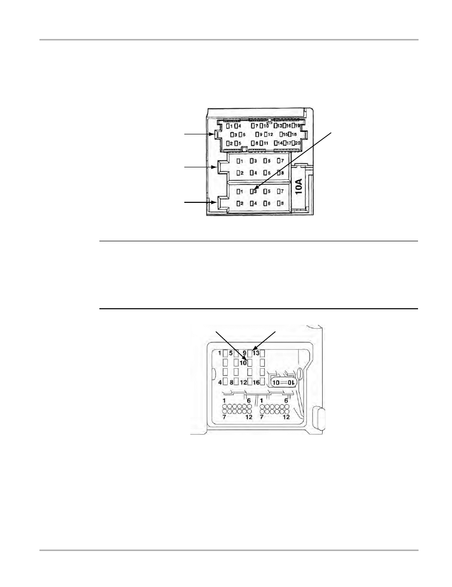
156
The Aftermarket Radio Problem
z
To repair the problem:
1.
Remove the radio.
2.
Make sure that the K-Line in the radio wiring harness (black 8-pin multi-connector III-T8) has
been removed from the connector and taped back to the harness (Figure B-2).
Figure B-2 K-Line on the radio wiring harness black 8-pin multi-connector III-T8
NOTE:
i
Some 2002 and newer Volkswagens come with the double-DIN “Premium VI” radio. This radio
does not have a K-Line connection, but rather has a CAN-high and CAN-low. Although the
connector is completely different and it should not be possible to have the “Aftermarket Radio
Problem” with these newer cars, if you use an aftermarket radio, it would be best to make sure that
nothing is connected to these pins in the radio harness. The back of the Premium VI radio is
shown in Figure B-3.
1— CAN–
2— CAN+
Figure B-3 Back of Premium VI radio
I
II
III
K-Line
1
2

157
Appendix C
Fuel Control Learning
Adaptation Values
VW/Audi uses a type of fuel control called “adaptive learning.” This is defined as the ability of the
engine management system to continuously modify the fuel mixture to account for changing
operating conditions.
OBD-II terms for fuel control are “short-term” and “long-term” fuel trim (FT).
•
Short term means the correction responds directly to the oxygen sensor (O2S) input.
•
Long term FT is designed to maintain short term FT in a balanced state, equal range of
control on either side of rich or lean.
The following sections explain OBD-II short and long term FT terminology applied to VW/Audi fuel
control terminology. VW/Audi use Bosch Motronic engine management systems. For VW,
Adaptive Learning started with the Motronic 2.9 engine management system in 1993. Each new
system increased the adaptation sophistication (M2.9, M5.0, M5.9.2, M7.0, M7.1, M7.5.1). For
these systems, two central fuel control terms require explanation:
•
Additive for idle adaptation.
•
Multiplicative for part throttle or cruise adaptation.
C.1 Long-Term Fuel Control
Both Additive and Multiplicative adaptation are a form of long term fuel control. Each is a coarse
type of FT control, allowing short term FT to maintain a midpoint balance between rich and lean.
C.1.1 Additive Adaptation
Additive means adding or subtracting equal amounts of fuel to every fuel block cell regardless of
the programmed base injection pulse value. It works very effectively for idle mixture related
problems, but its effect is minimal at the higher engine speeds. For example, vacuum leaks greatly
affect fuel mixture at idle but become less severe at higher RPM. The important distinction is that
the amount of fuel correction is not dependent upon the original base in each fuel memory cell.
Additive adaptation indicates a fine-tuning, long-term correction or adaptation that the ECM is
applying to the fuel injection pulse width. Although these minute adjustments affect the entire
engine speed range, they are most noticeable at idle or during lower pulse-width operating
conditions. A positive value indicates increased fuel injection duration, and a negative value
indicates a decreased fuel injection duration.
When the short term correction value, reaches its upper or lower limit, the ECM resets short term
correction and moves the long term FT value up or down by one count. The short term FT moves
quickly, while the long term FT moves slowly. The short and long term FT continue to work
together until the fuel mixture problem is corrected, or until the long term FT reaches its upper or
lower limit. When the long term FT reaches its limit, the ECM sets a DTC, and usually defaults into
open loop operation. The factory term “Additive Mixture Adaptation” refers to the fact that the ECM

158
Fuel Control Learning Adaptation Values
Long-Term Fuel Control
is adding directly to the injector opening time for all memory cells. However, data is only updated
under certain idle conditions. Be aware that Idle and Part Load Multiplicative work together to
establish the long term FT.
C.1.2 Multiplicative Adaptation
Multiplicative means multiplying or taking the preprogrammed cell base value and multiplying that
number by either a correction factor or percent. Here, the correction amount increased or
decreased in each memory block cell is dependent on each cell’s base injection pulse. This form
of adaptation is required to compensate for fuel control-type problems that get worse with
increased engine speed (i.e., a faulty injector). Short term FT in VW/Audi language is usually
called O2 regulation or O2 control. The readings are constantly changing, directly responding to
oxygen sensor (O2S) input. Normal readings are usually in the ±10% range with 0 as the midpoint.
If it gets too far off, Long-term additive or multiplicative adjusts the window back to the midpoint
(balanced state).
Multiplicative adaptation correction indicates the long-term FT correction that the ECM is applying
to the air/fuel mixture during closed loop operation over the middle to upper range of engine
operation. VW/Audi use the term “Multiplicative Mixture Adaptation” because it is a percent
correction factor based on the individual base injection value for each memory cell. Cells are
constantly updated based on feedback operation. If any cell stores an update that is beyond the
neutral feedback value, a correction is then factored into the injector pulse-width calculation. To
maintain the optimal air/fuel ratio of 14.7:1 for catalytic converter (CAT) efficiency, the ECM
monitors the O2Ss and calculated load. From this information, the ECM calculates a percent value
that indicates how much to enrich or dilute the fuel mixture. Sometimes, the ECM makes fine
tuning adjustments across the complete fuel map by adjusting the IDLE (Additive) FUEL TRIM (for
example, when a fine adjustment is needed across the range to compensate for fuel injector drift).
C.1.3 Examples of Display Groups for Long Term FT Adaptive Value
Depending on the year, vehicle, engine, and engine code, you may see some combination of the
following long term FT parameters:
•
ADPVALUEO2(ADD)(%)
•
ADPVALUEO2(IDLE)(ADD)(%)
•
ADPVALUEO2(MUL)(%)
•
ADPVALUEO2(P/T)(ADD)(%)
•
LEARNO2(ACTUAL)(BANK1)(%)
•
LEARNO2(ACTUAL)(BANK2)(%)
•
LEARNO2(BANK1)
•
LEARNO2(BANK1)(ADD)(%)
•
LEARNO2(BANK1)(IDLE)(%)
•
LEARNO2(BANK1)(MUL)(%)
•
LEARNO2(BANK1)(P/T)(%)
•
LEARNO2(BANK2)
•
LEARNO2(BANK2)(%)

159
Fuel Control Learning Adaptation Values
Long-Term Fuel Control
•
LEARNO2(BANK2)(ADD)(%)
•
LEARNO2(BANK2)(IDLE)(%)
•
LEARNO2(BANK2)(MUL)(%)
•
LEARNO2(BANK2)(P/T)(%)
•
LEARNO2(BK1-SNS1)(IDLE)(%)
•
LEARNO2(BK1-Sensible/T)(%)
•
LEARNO2(BK2-SNS1)(IDLE)(%)
•
LEARNO2(BK2-SNS1)(P/T)(%)
•
LEARNO2(FULL)
•
LEARNO2(IDLE)
•
LEARNO2(IDLE)(%)
•
LEARNO2(IDLE)(ADD)(%)
•
LEARNO2(IDLE)(ADD)(%)
•
LEARNO2(IDLE)(ms)
•
LEARNO2(IDLE)(MUL)(%)
•
LEARNO2(P/T)
•
LEARNO2(P/T)(%)
•
LEARNO2(P/T)(ADD)(%)
•
LEARNO2(P/Tumult)(%)
•
LEARNO2(P/T-WOT)
•
LEARNO2(PART)(MUL)(%)
•
LEARNVALUEMIXTUREADAPTATION
•
LEARNVALUEMIXTURECORR(%)
•
LEARNVALUEMIXTURECORR(ms)
•
LEARNVALUEO2(P/T)(ADD)(%)
•
LRNO2BEFORECAT(P/T)(ADD)(%)
•
LRNO2BEFORECAT(IDLE)(ADD)(%)
•
LRNO2BEFORECAT(P/T)(ADD)(%)
•
LEARNVALUEO2(IDLE)(ADD)(%)
•
LEARNVALUEO2(P/T)(MUL)(%)
•
ADPVALUEMIXTURE(BANK1)(%)
•
LRNO2BEFORECAT(IDLE)(ADD)(%)
•
LEARNMIXT(BANK1)(IDLE)(%)
•
LEARNMIXT(BANK1)(P/T)(%)
•
LEARNMIXT(BANK1)(P/T1)(%)
•
LEARNMIXT(BANK1)(P/T2)(%)
•
LEARNMIXT(BANK1)(P/T3)(%)
•
LEARNMIXT(BANK2)(IDLE)(%)
•
LEARNMIXT(BANK2)(P/T)(%)
•
LEARNMIXT(BANK2)(P/T1)(%)
•
LEARNMIXT(BANK2)(P/T2)(%)
•
LEARNMIXT(BANK2)(P/T3)(%)

160
Fuel Control Learning Adaptation Values
Short-Term Fuel Control
•
LEARNMIXTURE(BANK1)(%)
•
LEARNMIXTURE(BANK2)(%)
Below is a typical display group, Group (32), “LEARN VALUES O2”.
•
LEARN VALUE O2(BK 1)(IDLE)(%)
•
LEARN VALUE O2(BK 2)(IDLE)(%)
•
LEARN VALUE O2(BK 1)(P/T)(%)
•
LEARN VALUE O2(BK 2)(P/T)(%)
C.1.4 Important Tips for Long Term Fuel Control
•
The value typically ranges from -10 to +10. A normal operating engine should fluctuate only
slightly. If more than ±7%, perform a mixture diagnosis. Technicians report MAF sensor
problems with readings of ±5%.
•
Use Basic Settings for faster adaptation relearn. Take short road test (usually 2–3 miles) with
the scan tool hooked up in Basic Settings. For relearn, make sure the engine is at normal
operating temperature (coolant minimum temperature of 167°F [75°C] and a maximum intake
air temperature of 194°F [90°C]). For idle relearn, let the engine idle in Basic Settings for a few
minutes. For road test in Basic Settings, perform multiple accelerations and decelerations, as
well as a part throttle cruise. Check to see that learn values are back within normal range. If
OK, clear the codes. Field technicians report faster relearn and verification of repair by not
clearing codes until correct fuel control has been confirmed). Finish by setting all Readiness
Codes, and then one more final road test (see “Basic Settings and Fuel Trim Accelerated
Learning” on page 48).
•
Some vehicles may have part throttle learning divided into 3 different parts: (P/T1, P/T2, P/
T3). Check to see that each part is in proper specification.
•
For most systems that have FT control using ±25% maximum range, readings above or below
14 sets a DTC and turns on the MIL.
C.2 Short-Term Fuel Control
Short term FT is usually called O2 regulation or O2 control. The readings are constantly changing,
directly responding to O2S input. Normal readings usually are in the ±10% range with 0 as the
midpoint. If it gets too far off, Long-term additive or multiplicative adjusts the window back to the
midpoint (balanced state).
C.2.1 Examples Short Term FT O2 Regulation
Depending on the year, vehicle, engine and then engine code you may see some combination of
the following short term FT parameters:
•
ADPVALUEMIXTURE(BANK1)
•
ADPVALUEMIXTURE(BANK2)
•
ADPVALUEMIXTURE(BANK2)(%)
•
ADPVALUEO2

161
Fuel Control Learning Adaptation Values
Short-Term Fuel Control
•
LEARNVALUEO2
•
O2CONTROL(BANK1)(%)
•
O2CONTROL(BANK2)(%)
•
O2CONTROLFACTOR(BK1)
•
O2CONTROLFACTOR(BK1)(%)
•
O2CONTROLFACTOR(BK2)
•
O2CONTROLFACTOR(BK2)(%)
•
O2REGULATION(BK1-SNS1)(%)
•
O2REGULATIONBEFORECAT(%)
•
O2SENSOR(BK1-SNS1)(V)
•
DYNAMIC FACTOR O2-SNSBEFORECAT
•
O2CONTROL(BANK1)(%)
•
O2CONTROL(BANK2)(%)
•
O2CONTROLDEVIATION(%)
•
O2INTEGRATOR
Below is a typical short term FT display group, Group O2 REGULATION BEFORE CAT
•
O2 SENSOR(BANK 1,BEFORE CAT)(V)
•
O2 SENSOR(BANK 2,BEFORE CAT)(V)
•
O2 REGULATION (BANK 1)(%)
•
O2 REGULATION (BANK 2)(%)
These parameters are equivalent to the short term FT correction during closed loop operation.
This correction is based on the O2S input for a given engine load and speed. The ECM monitors
engine operating conditions and calculates short-term and long-term adaptations to correct for
engine wear.
The value typically range is ±10. A normal operating engine should see this value fluctuate by at
least 2%. If it fluctuates by more than 7%, perform a fuel mixture diagnosis.
NOTE:
i
Some vehicles use a calculated value called factor. The parameter names are ADP VALUE O2
and DYNAMIC FACTORO2, SNS BEFORE CAT. Normal range is 0.5–1.5;
1.0 ±0.3 is base midpoint; for 2.8L (AAA), the range is 0.80–1.20.
Positive values indicate the ECM is enriching the air/fuel mixture, and negative values indicate the
ECM is leaning the mixture.
During open loop operation, the ECM runs at a base program without correction and the
parameter displays a fixed 0% value. The ECM adjusts the air/fuel mixture by changing the fuel
injector pulse width.
C.2.2 Important Tips for Short-Term Fuel Control
•
On some OBD-I (1991–1995) vehicles, values for short term FT, LEARN O2 (IDLE), LEARN
O2 (P/T), or LEARN O2 (FULL), may be mislabeled as reading in percentage. In actuality,
they are reading a numeric factor of 1.0 midpoint ±0.5 (0.5 to 1.5). For 2.8L AAA engine, the
range is 0.80–1.20.

162
Fuel Control Learning Adaptation Values
Oxygen Sensor Voltage
•
Range: 0.5 - 1.5 Normal Value: 1.0 ±0.3 (0.7–1.3) is base midpoint
•
For 2.0L (ABA) IDLE ADAPT: 0.87–1.2
•
For 2.8L (AAA) IDLE ADAPT: 0.53–1.47
•
Part Load: 0.80–1.20
•
Low Load: 0.53–1.47
•
Adaptation values may be erased if the car battery goes low or is disconnected.
•
Additive adaptation is used mostly to correct idle mixture, however, it may also be used at
higher RPM for fine adjustment (may see different additive values at different RPM). With
relearn, it is normal for Additive adaptation to respond quickly. Multiplicative learning typically
requires more learning time and vehicle must be driven on an extended road test under
various driving conditions.
•
For most systems that have FT control using ±25% maximum range, readings above or below
14 sets a DTC and turn on MIL.
C.3 Oxygen Sensor Voltage
Typical displays to view O2S voltage are either 001–004 (basic) or 026/033. You may see some
combination of the following parameters:
•
O2SENSOR(V)
•
O2SENSOR1(V)
•
O2SENSOR2(V)
•
O2SENSOR(BANK1)(V)
•
O2SENSOR(BANK1,AFTERCAT)(V)
•
O2SENSOR(BANK1,BEFORECAT)(V)
•
O2SENSOR(BANK2)(V)
•
O2SENSOR(BANK2,AFTERCAT)(V)
•
O2SENSOR(BANK2,BEFORECAT)(V)
•
O2SENSOR(BK1-SNS1)(V)
•
O2SENSORAFTERCAT(V)
•
O2SENSORAFTERCATBK1(V)
•
O2SENSORAFTERCATBK2(V)
•
O2SENSORBEFORECAT(V)
These parameters indicate the amount of oxygen in the exhaust gas. High oxygen levels indicate
a lean air/fuel mixture, while low oxygen levels indicate a rich air/fuel mixture. When the O2Ss are
at operating temperature and the system is operating in closed loop, the ECM constantly adjusts
the air/fuel mixture to achieve a 14.7:1 ratio. The ECM uses O2S signals to determine how rich or
lean the engine is running and to correct the mixture.
C.4 Early Vehicle Oxygen Sensor Reading
Many early vehicles, model years 1990–93, with limited display groups may not read O2S or O2
control. However, you can use Expert Mode and select display group 000. O2V reads in binary

163
Fuel Control Learning Adaptation Values
Late Model Oxygen Sensor Reading
format (0–255). There is no consistency, but Channel 5 often reads the O2 signal. Look for this
number to be constantly varying up and down by at least 14 digits. If Channel 5 is not active, it may
be an application that only displays an O2 short term FT factor. In this case, check channel 4. The
O2 control factor will also output a binary 0–255 number with 128 as the midpoint. Numbers less
than 128 indicate a rich mixture correction. Numbers higher than 128 indicate a lean mixture
correction. Look for fast fluctuations at different RPM and load conditions which indicate an active
O2S (use DVOM to test O2S directly). Above is for those vehicles with display group 000 only. On
vehicles with additional display groups but still not displaying O2V directly, look at the O2 Factor
which reads 1.0 as the base point. Higher numbers indicate correction for a mixture too lean and
lower numbers indicate a correction for a mixture too rich. A typical normal range is 1.0 ±0.3.
The following sections are display examples for late model OBD-II O2S and CAT tests.
C.4.1 Example: Motronic 2.9 (1993–1995)
The following example concerns reading engine data display Group 000.
Display group 000 has 10 channels or display fields, listed below.
1.
Coolant temperature
2.
Engine load
3.
RPM
4.
O2 factor
5.
Idle Adapt
6.
Part throttle adapt
7.
Low load adapt
8.
IAC adapt
9.
Not used
10. IGN timing
The display fields are output in binary numbers. To understand the binary number, visualize a
clock with 0 at the top center. The number 128 is at the center bottom. The binary clock counts
from 0 to 255.
The number can theoretically range from 0 to 255 with 0 as the midpoint. A number of 13 to 128
indicates that the ECM has commanded an overall lean mixture correction. A number of 128 to
243 indicates that the ECM has commanded an overall rich mixture correction.
C.5 Late Model Oxygen Sensor Reading
Some late models are using 0–5V O2Ss. Rich is high voltage; lean is low voltage. For example, a
VW 2001 2.0L with the AEG engine and the 2002 Passat W8 (BDP). Other late model vehicles
may be using a Linear Air/Fuel Ratio sensor (A/F sensor) which measures the exact air/fuel
mixture (not like a standard Zirconium O2S switching constantly between rich and lean). The
voltage displayed (display group 33 in Table C-1 below) for these is an ECM computed value
where 1.5V = 1 lambda or the ideal fuel mixture ratio of 14.7:1. Higher voltage indicates correction
for a rich mixture and lower voltage indicates a correction for a lean mixture. Under normal load,
the A/F sensor voltage should vary around 1.5V, which means the mixture is right at stoichiometric

164
Fuel Control Learning Adaptation Values
Late Model Oxygen Sensor Reading
or Lambda = 1. During deceleration from 3000 RPM, the mixture is lean and the A/F sensor
voltage should go higher than 1.5V. Under full load acceleration, the mixture is rich and the A/F
sensor voltage should go low, 1V or lower.
NOTE:
i
The broadband lambda probe linear Air Fuel Ratio Sensor acquires and evaluates lambda values
differently to the step type zirconium O2S. The lambda value (display group 31 in Table C-1) is
determined from a change of current, not from a change of voltage.
C.5.1 Oxygen Sensor Aging Test
The O2S Aging Test is a Readiness Code test, typically display groups 34 or 35 for O2S before
CAT, and display groups 36 or 43 for O2S after CAT.
Typical display Group, DIAGN AGING O2 BEFORE CAT
•
ENGINE SPEED(rpm)
•
EXHAUST GAS TEMPERATURE
•
DYNAMIC FACTOR
•
DIAGNOSE STATUS
Depending on the year, vehicle, engine, and engine code, you may see some combination of the
following O2S Aging Test Parameter list:
•
AGINGTESTO2(BK1-SNS2)
•
AGINGTESTO2(BK2-SNS2)
•
AGINGTESTO2AFTERCATBK1
•
AGINGTESTO2AFTERCATBK2
•
AGINGTESTO2-SNSAFTERCAT
•
AGINGTESTO2-SNSBEFORECAT
•
DIAGNOSESTATUS
•
DYNAMICFACTOR
•
DYNAMICFACTORO2-SNSBEFORECAT
These parameters indicate the Readiness Code for the O2S Aging test. The test measures the
O2S cycling time between a rich to lean transition back to rich transition. This measurement then
translates into the aging condition of the O2S. If the specified allowable time is exceeded,
DIAGNOSESTATUS will read NOT OK. A typical normal range for the cycling time period duration
(DYNAMICFACTOR) is 0.1–1.8 seconds (typical functional range is 0–3.3 seconds).
Table C-1
Display groups 31 and 33
Display
Group
Sensor
Bank 1,
Sensor 1
Bank 1,
Sensor 2
Bank 2,
Sensor 1
Bank 2,
Sensor 2
31
Linear oxygen
sensors
Lambda
actual value
Lambda
specified value
33
Linear oxygen
sensor control
value
Control
value (%)
Sensor voltage
before CAT of a
broadband
sensor (V)
Control
value (%)
Sensor voltage
before CAT of a
broadband
sensor (V)

165
Fuel Control Learning Adaptation Values
Late Model Oxygen Sensor Reading
C.5.2 Oxygen Sensor Control-Dwell Time Test
Below is a typical display group example, DIAGN O2 CONTROL SYSTEM.
•
ENGINE LOAD(%)
•
O2 SENSOR(BANK 1, AFTER CAT)(V)
•
CORR.BETW O2-SNS 1+2 BK1(ms)
•
DIAGNOSE STATUS
These parameters indicate the relationship of the before CAT O2S and the after CAT O2S. The
after CAT O2S has the authority to override the before the CAT O2S. The reason for this is in case
the before CAT O2S performance deteriorates to the point of jeopardizing the CAT, the after CAT
O2 control can take over control preventing possible CAT damage. The after CAT O2S also can
correct for slight changes in the mixture if it detects displacement of the before CAT voltage curve.
It takes control by holding the before CAT O2 control at its higher or lower point for a specific time
(dwell time). If this time is in the positive range (i.e., 50 ms), then the mixture is shifted to the rich
direction. If the time is negative (i.e., -50 ms), then the mixture is shifted to the lean direction.
NOTE:
i
If the value is above +200 ms, then there is a possible leak in the exhaust system.
C.5.3 CAT Test Parameters
Below is a typical display group 46/47, DIAGNOSE CATALYST BANK 1.
•
ENGINE SPEED(rpm)
•
CATALYST TEMPERATURE
•
CATALYST EFFICIENCY
•
DIAGNOSE STATUS
The engine management ECM compares the voltage(s) of the upstream or before CAT O2S to the
voltage(s) of the downstream or after the CAT O2S. The result is called the amplitude ratio
between the two sensors and indicates the CAT test result in either percent or amplitude ratio. A
good CAT amplitude ratio range is 0.00 –0.32.
Table C-2 provides O2S and fuel control display fields available in Expert Mode.
Table C-2
Display fields for O2S and Fuel control available in Expert Mode (part 1 of 5)
Display
Group
Sensor
Bank 1,
Sensor 1
Bank 1,
Sensor 2
Bank 2,
Sensor 1
Bank 2,
Sensor 2
30
Oxygen sensor,
status (2-bank
system)
XXX
1
XXX
1
XXX
1
XXX
1
Oxygen sensor,
status (1-bank
system)
XXX
1
XXX
1
X values: (1) Control Active, (2) Sensor Ready, (3) Sensor Heater ON
1
Condition attained = 1; Condition not attained = 0

166
Fuel Control Learning Adaptation Values
Late Model Oxygen Sensor Reading
31
Knock sensor
voltage
(V)
(V)
(V)
(V)
Oxygen sensor
voltage
(V)
(V)
Linear oxygen
sensors (2-bank
system)
Lambda
actual value
Lambda
specified value
Lambda
actual value
Lambda
specified value
Linear oxygen
sensors (1-bank
system)
Lambda
actual value
Lambda
specified value
32
Oxygen sensors
learning values
(maximum value)
(2-bank systems)
Idle (%)
Partial load (%)
Idle (%)
Partial load (%)
Oxygen sensors
learning values
(maximum value)
(1-bank systems)
Idle (%)
Partial load (%)
33
Lambda control
value (2-bank
system)
Control value
(%)
Oxygen sensor
voltage (V)
Control value
(%)
Oxygen sensor
voltage (V)
Lambda control
value (1-bank
system
Control value
(%)
Oxygen sensor
voltage (V)
Linear oxygen
sensor control value
Control value
(%)
Sensor voltage
before CAT of a
broadband
sensor (V)
Control value
(%)
Sensor voltage
before CAT of a
broadband
sensor (V)
34
Oxygen sensor
aging test Bank 1 or
Bank 3 before CAT,
short trip
RPM (1/min.)
Exhaust gas/
CAT
temperature
(°C)
Length of
period (s)
Result (Test
ON/Test OFF/
B1-S1 OK/
B1-S1 not OK/
B3-S1 OK/
B3-S1 not OK)
Oxygen sensor
aging test Bank 1 or
Bank 3 before CAT
for linear oxygen
sensors, short trip
RPM (1/min.)
Exhaust gas/
CAT
temperature
(°C)
Dynamic
factor
Result (Test
ON/Test OFF/
B1-S1 OK/
B1-S1 not OK/
B3-S1 OK/
B3-S1 not OK)
Table C-2
Display fields for O2S and Fuel control available in Expert Mode (part 2 of 5)
Display
Group
Sensor
Bank 1,
Sensor 1
Bank 1,
Sensor 2
Bank 2,
Sensor 1
Bank 2,
Sensor 2
1
Condition attained = 1; Condition not attained = 0

167
Fuel Control Learning Adaptation Values
Late Model Oxygen Sensor Reading
35
Oxygen sensor
aging test Bank 2 or
Bank 4 before CAT,
short trip
RPM (1/min.)
Exhaust gas/
CAT
temperature
(°C)
Length of
period (s)
Result (Test
ON/Test OFF/
B2-S1 OK/
B2-S1 not OK/
B4-S1 OK/
B4-S1 not OK)
Oxygen sensor
aging test Bank 2 or
Bank 4 before CAT
for linear oxygen
sensors, short trip
RPM (1/min.)
Exhaust gas/
CAT
temperature
(°C)
Dynamic
factor
Result (Test
ON/Test OFF/
B2-S1 OK/
B2-S1 not OK/
B4-S1 OK/
B4-S1 not OK)
Oxygen sensor
aging test Bank 2
before CAT
36
Oxygen sensor
readiness after CAT,
short trip (2-bank
system)
Sensor
voltage (V)
Result (Test
ON/Test OFF/
B1-S2 OK/
B1-S2 not OK/
B3-S2 OK/
B3-S2 not OK
Sensor
voltage (V)
Result (Test
ON/Test OFF/
B2-S2 OK/
B2-S2 not OK/
B4-S2 OK/
B4-S2 not OK)
Oxygen sensor
readiness after CAT,
short trip (1-bank
system)
Sensor
voltage (V)
Result (Test
ON/Test OFF/
B1-S2 OK/
B1-S2 not OK
37
Oxygen sensors,
short trip
Load (%)
Oxygen sensor
voltage after
CAT (V)
TV shift (ms)
Result (Test
ON/Test OFF/
Sys. OK/Sys.
not OK)
Linear oxygen
sensors, short trip
Load (%)
Oxygen sensor
voltage after
CAT (V)
Lambda
Result (Test
ON/Test OFF/
Sys. OK/Sys.
not OK)
38
Oxygen sensors,
short trip
Load (%)
Oxygen sensor
voltage after
CAT (V)
TV shift (ms)
Result (Test
ON/Test OFF/
Sys. OK/Sys.
not OK)
Linear oxygen
sensors, short trip
Load (%)
Oxygen sensor
voltage after
CAT (V)
Lambda
Result (Test
ON/Test OFF/
Sys. OK/Sys.
not OK)
Oxygen sensors
(1-bank systems)
NOT USED
39
Sensor exchange
after CAT, short trip
Air mass (g/s)
Sensor voltage
(V)
Sensor
voltage (V)
Result (Test
ON/Test OFF/
Sys. OK/Sys.
not OK)
Table C-2
Display fields for O2S and Fuel control available in Expert Mode (part 3 of 5)
Display
Group
Sensor
Bank 1,
Sensor 1
Bank 1,
Sensor 2
Bank 2,
Sensor 1
Bank 2,
Sensor 2
1
Condition attained = 1; Condition not attained = 0

168
Fuel Control Learning Adaptation Values
Late Model Oxygen Sensor Reading
40
Oxygen sensor
heaters resistor
(combined wires of
heaters)
Heater
resistor (
Condition
(Heater before
CAT ON/Heater
before CAT
OFF)
Heater
resistor (
Condition
(Heater before
CAT ON/Heater
before CAT
OFF)
(1-bank systems)
NOT USED
41
Oxygen sensor
heater
Heater
resistor (
Condition
(Heater before
CAT ON/Heater
before CAT
OFF/Sensor 1
(%))
Heater
resistor (
Condition
(Heater before
CAT ON/Heater
before CAT
OFF)
42
Oxygen sensor
heaters (separate
wires of heaters)
Heater
resistor (
Condition
(Heater before
CAT ON/Heater
before CAT
OFF/Sensor 1
(%))
Heater
resistor (
Condition
(Heater before
CAT ON/Heater
before CAT
OFF)
43
Oxygen sensor
aging after CAT,
linear oxygen
sensors, short trip
RPM (U/min.)
Exhaust gas/
CAT
temperature
(°C)
Oxygen
sensor
voltage (V)
Result (Test
ON/Test OFF/
B1-S2 OK/
B1-S2 not OK/
B3-S2 OK/
B3-S2 not OK)
44
Oxygen sensor
aging after CAT,
short trip
RPM (U/min.)
Exhaust gas/
CAT
temperature
(°C)
Oxygen
sensor
voltage (V)
Result (Test
ON/Test OFF/
B2-S2 OK/
B2-S2 not OK/
B4-S2 OK/
B4-S2 not OK)
45
46
CAT conversion test
Bank 1 or Bank 3,
short trip
RPM (1/min.)
CAT
temperature
(°C)
Measuring
value CAT
conversion
Result (Test
ON/Test OFF/
CAT B1 OK/
CAT B1 not OK/
CAT B3 OK/
CAT B2 no OK)
47
CAT conversion test
Bank 2 or Bank 4,
short trip
RPM (1/min.)
CAT
temperature
(°C)
Measuring
value CAT
conversion
Result (Test
ON/Test OFF/
CAT B2 OK/
CAT B2 not OK/
CAT B4 OK/
CAT B4 no OK)
CAT conversion test
Bank 2 (1-bank
systems)
NOT USED
Table C-2
Display fields for O2S and Fuel control available in Expert Mode (part 4 of 5)
Display
Group
Sensor
Bank 1,
Sensor 1
Bank 1,
Sensor 2
Bank 2,
Sensor 1
Bank 2,
Sensor 2
1
Condition attained = 1; Condition not attained = 0

169
Fuel Control Learning Adaptation Values
Late Model Oxygen Sensor Reading
48
Thermal CAT
diagnosis Bank 1,
short trip
Operating
system BDE
XXXXXXXX
1
Number of test
steps (-)
Exothermal
temp.
increase (K)
Result (Test
ON/Test OFF/
Sys. OK/Sys.
not OK)
X values: (1) With bit homogenous knock protection, (2) Not used, (3) Not used, (4) Layer
CAT heating double inject., (5) Layer, (6) Homogenous layer double inject., (7)
Homogenous lean, (8) Homogenous
49
Thermal CAT
diagnosis Bank 2,
short trip
Operating
system BDE
XXXXXXXX
1
Number of test
steps (-)
Exothermal
temp.
increase (K)
Result (Test
ON/Test OFF/
Sys. OK/Sys.
not OK)
X values: (1) With bit homogenous knock protection, (2) Not used, (3) Not used, (4) Layer
CAT heating double inject., (5) Layer, (6) Homogenous layer double inject., (7)
Homogenous lean, (8) Homogenous
Table C-2
Display fields for O2S and Fuel control available in Expert Mode (part 5 of 5)
Display
Group
Sensor
Bank 1,
Sensor 1
Bank 1,
Sensor 2
Bank 2,
Sensor 1
Bank 2,
Sensor 2
1
Condition attained = 1; Condition not attained = 0

170
Index
A
ABS systems 72
basic settings brake bleeding 75
actuator tests 43
important notes for testing 45
aftermarket radio problem 11
application charts
ABS (Audi types and system descriptions) 74
ABS (VW types and system descriptions) 73
ABS (VW) 72
engine (Audi) 37
engine (early Audi) 40
engine (early VW) 36
engine (VW) 32
transmission (types and descriptions) 53
transmissions 57
VW/Audi software 30
B
basic settings 41
ABS 75
adaptive learned values 48
crankshaft sensor learn 49
Expert Mode 20
fuel trim accelerated learning 48
ignition timing 47
kickdown function 46
menu choices 46
problems with 50
standard mode 45
throttle body adaptation 46
transmission testing 63
C
checking for codes (test drive) 40
coding and programming
VW 1996–99 mechanical keys 80
D
data display (ignition off) 42
data groups (pre-selected) 43
data parameters
ABS 150
diesel engine 136
gas engine 105
listed alphabetically 93
transmission 140
transmission Expert Mode 148
display data groups 23
DL-16 11
E
early Audi engine systems 37
early VW engine systems 36
ECU coding 23
ECU ID information 21
electronic throttle 67
emergency running or limp-home mode 71
electronic throttle systems 67
engine ID codes 5
engine systems
important notes for fault codes 41
system coverage 36
systems covered 32
engine trouble codes 41
Expert Mode 18
–
automatic system test 16
important warnings 18
selecting 11
VW/Audi software applications 30
F
false codes 41
fuel control 157
additive adaptation 157
early vehicle O2S 162
Expert Mode display groups 164
late model O2S 163
multiplicative adaptation 158
O2 factor 161
oxygen sensor voltage 162
fuel control learning 157
functional tests
Initiate Actuator Tests 43
Review ECU ID 45
Service Interval Reset 50
I
Immobilizer 75
ECU replacement 77
FAQ 82
key coding 77
remote key matching 81
sample remote key option settings 81
types of 75

171
Index
K
K
keys
actuator tests 22
adaptations 27
basic settings 47
electronic throttle adaptation 67
Personality Keys™. See Personality Keys™
types used with immobilizer systems 75
KW2000 protocol 27
L
login access numbers 28
long-term fuel control 157
M
multiple code clearing 40
P
Personality Keys™ 11
programming. See coding and programming
R
remote key option settings 81
S
Safety iii
–
safety
information iii
scan tool VW/Audi coverage 30
service reset
service reset/preset functions 52
short-term fuel control 160
T
test adapters 11
testing
ABS systems 72
engine systems 32
transmission systems 53
transmission systems 53
application chart 57
basic settings 63
emergency operation 66
fail-safe functions 65
important tips for fault codes 62
series 01F, 01K 61
series 01N 60
series 095, 096, 01M 60
solenoid firing 64
V
vehicle connectors
VW locations 13
VW-1 11
W
Work Shop Code (WSC) 21
Document Outline
- Safety Information
- Using This Manual
- Introduction
- Operations
- Expert Mode
- Testing
- Data Parameters
- Terms and Acronyms
- Troubleshooting
- Fuel Control Learning Adaptation Values
- Index
Wyszukiwarka
Podobne podstrony:
Mercedes Benz Vehicle Communication Software Manual EAZ0025B41C
VAG 2013 Volkswagen & Audi OBD II Readiness Code Charts February 2013
Audi A3 (2004) Workshop Manual
ilexa Onboard Diagnostics VAG COM VolksWagen service indicator resetting
Murexin CD Manual 2013 V0 63
ebooks de volkswagen transporter 1980 service manual (osiol net) www!osiolek!com L2MGLGLNG46LHEIWGVH
Dtc Volkswagen Seat Audi Skoda2
Programowanie klawiszy radia Audi, diagnostyka samochodu, Diagnostyka dokumety, procedury diagnostyc
TACHOPRO TACHO SOFTWARE COMPLETE KIT FOR CHEAP OBD2 OBD VW AUDI BMW MERCEDES SEAT SKODA FORD SOFTWAR
Manual Vag Com
A1 3 CARVALHO, João M S (2013) The Crucial Role of Internal Communication Audit to Improve Internal
Kałuska, Angelika The role of non verbal communication in second language learner and native speake
C5 (X7) D6AY01KAP0 9 23 07 2013 Pomoc w diagnostyce Manualna (mechaniczna) skrzynia biegów i sp
Volkswagen Golf Variant 2007, Golf Variant 2010, Jetta 2005 Auxiliary heater Edition 03 2010 Work
ESQUEMA COMPLETO NTDD AUDI SEAT VW SKODA VP38 Grupo VAG 30
TACHOPRO TACHO SOFTWARE COMPLETE KIT FOR CHEAP OBD2 OBD VW AUDI BMW MERCEDES SEAT SKODA FORD SOFTWAR
Manual Instalacion Plafon Audi a4 a3 Con Leds Ambiente En Se
więcej podobnych podstron