
Bosch Motronic 4.3 Engine Management Unit - Part 2
Bosch Motronic 4.3 Engine Management
Unit - Part 2
Please read and understand the disclaimer before you go on.
Okay, so let's recap. We have opened up the ECU, and established that it uses a Siemens
microcontroller. Firmware is stored in an external 64k-bit x 8 FLASH device. I suggest that before
proceeding any further you take the time to read through the data sheets for these two devices. In doing
this you will understand the architecture of such devices before we begin to modify anything.
So how do we access the Firmware stored on the FLASH device? I will go back slightly and explain
that years ago I delved in modifying Nintendo Game boy cartridges as well as having a go at writing
small programs for such devices. So how does this relate to the ECU you may ask? Well the Game boy
cartridges come as standard with ROM devices fitted. The cartridges were modified by removal of the
ROM device and replacement with a FLASH chip. Furthermore these cartridges utilised a simple
software selecting, or memory switching, circuit. This meant that several games could be stored on a
single FLASH device and be switched between them thereby preventing the need to continually swap
cartridges to play different games.
I would highly recommend that you visit the following site and have a read through it. It will give
you some great grounding in what is being achieved here.
http://www.ziegler.desaign.de/readplus.htm#4MBit%20home
I would like to stress that this is not the final method that will be deployed. It is merely a way of
showing you that a large FLASH device can be used to store several different programs and that they
can be accessed by switching between the different memory banks of the FLASH device. For our ECU
application, we could theoretically have several different firmware programs stored on a single FLASH
device. To thereafter access any one of them would require a simple memory bank switching device. We
will not be using the 'MB5' concept explained in the Nintendo pages. This is because it requires software
coding to switch between memory banks. This project will use a straight forward hardware select device.
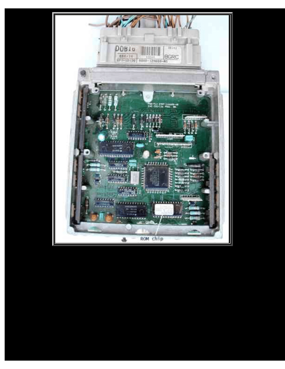
The concept of what is being done is not new. In fact many Ford owners have been 'tweaking' their
EEC-IV ECU's for many years. Here is an image of the internals of an EEC-IV ECU;
http://www.volvospeed.com/obd2/partii.htm (1 of 5)12/6/2005 4:58:47 PM
Bosch Motronic 4.3 Engine Management Unit - Part 2
To the bottom right corner of the image is a chip with a white label thereon. This is the ROM chip
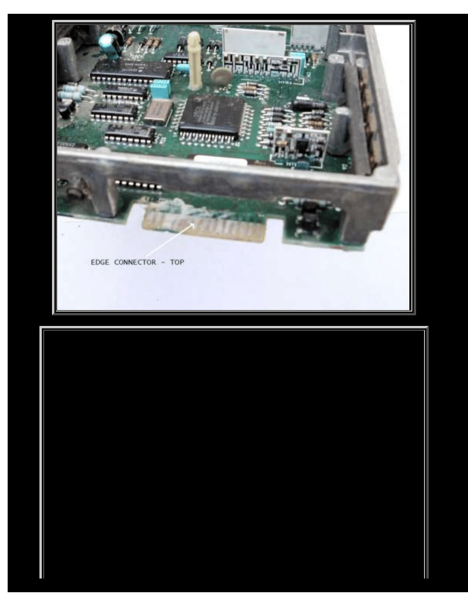
containing this ECU's firmware. In the next images you will see that there is an edge connector located
adjacent to the ROM chip
http://www.volvospeed.com/obd2/partii.htm (2 of 5)12/6/2005 4:58:47 PM
Bosch Motronic 4.3 Engine Management Unit - Part 2
http://www.volvospeed.com/obd2/partii.htm (3 of 5)12/6/2005 4:58:47 PM
Bosch Motronic 4.3 Engine Management Unit - Part 2
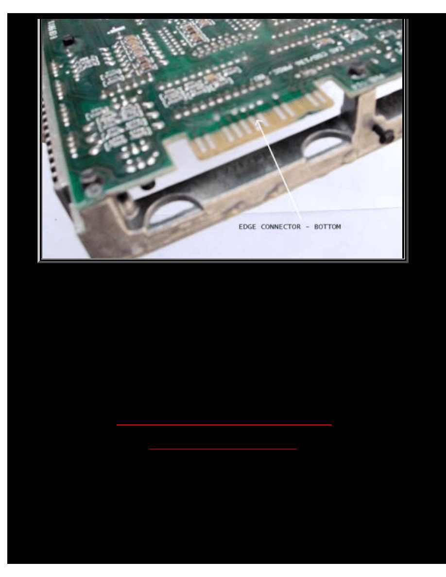
The edge connector is the point at which the address, data and control lines for the Rom chip are
brought out of the board to a common port. Included on the edge connector is a ROM disable line. When
activated, the onboard ROM is disabled and the microcontroller looks for a program device on this port
from which to read firmware data. This is the method used by many chip tuners. They modify the maps
and blow an EPROM on a purpose made carrier board. This board is then plugged into this edge
connector, disabling the onboard Rom. When the ECU is 'booted' up, the microcontroller runs the
firmware now stored in the EPROM on the plugged in carrier.
If you wish, I suggest a search of the internet in respect of this method of reprogramming /
modifying the ROM firmware. A couple of examples are:
http://acc-electronics.com/cloud/efi/amarch/eec.htm
http://www.tweecer.com/index.html
Okay, so now we have an understanding of how to 'attack' the hardware of ECU's. Let's move on
and look at how we can modify these examples to work with the Bosch Motronic 4.3 ECU.
A number of years ago a site appeared on the internet whereby the author went into great detail on
how to modify a Margneti Marelli ECU. His project involved the reversing of the firmware. An
http://www.volvospeed.com/obd2/partii.htm (4 of 5)12/6/2005 4:58:47 PM

Bosch Motronic 4.3 Engine Management Unit - Part 2
interesting point to mention is that he actually found that the firmware coding was not bug free. In
certain situations the ECU could in fact not work correctly for the given conditions. Again, I would
suggest taking a look at his website, and reading through the numerous pages. It was this site that gave
me the inspiration to become involved in Engine Management Systems. You may find some of the
information very technical, but it is very clear and again will give a good grounding in what is being
achieved here.
http://www.sonic.net/~mikebr/efi/ecu_hdwr.html
In the next section I will move onto modifying the Bosch Motronic 4.3 ECU.
http://www.volvospeed.com/obd2/partii.htm (5 of 5)12/6/2005 4:58:47 PM
Document Outline
- volvospeed.com
Wyszukiwarka
Podobne podstrony:
BOSCH Motronic?U?ult Codes
Engine Management Fault Finding
Bosch Motronic Mp 9 0
Bosch Motronic
Upstream Intermediate Student s Book UNIT 2 PART 2
Upstream Intermediate Student s Book UNIT 2 PART 3
11 P2 Engine Management Sys
Engine Management Fault Finding
Bosch Motronic Mp 9 0, Magneti Marelli 1Av, Motormanagement Systeme
Bosch Motronic ME 7, ME 7 1, ME 7 1 1, ME 7 5 System Strategy
Volkswagen 2 0l 85 kW Motronic, engine code BHY Edition 10 2005 Current Flow Diagram
Upstream Intermediate Student s Book UNIT 6 PART 2
Bosch Motronic ME7 Description[1]
Electronic engine management and calibration
Upstream Intermediate Student s Book UNIT 4 PART 1
Upstream Intermediate Student s Book UNIT 1 PART 1
Upstream Intermediate Student s Book UNIT 4 PART 2
więcej podobnych podstron