
Digital Still Camera Image
File Format Standard
(Exchangeable image file format
for Digital Still Cameras: Exif)
Version 2.1
June 12, 1998
Japan Electronic Industry Development Association
(JEIDA)

This standard makes no warranty, express or imp lied, with respect to the use of any intellectual property, such as patents,
copyrights and trademarks, belonging to any corporation or individual. Nor does this standard make any warranty
regarding system reliability or product liability.
Windows
™
is a registered trademark of Microsoft Corporation in the United States and elsewhere. FlashPix
™
is a
registered trademark of Eastman Kodak Company.

Revision History
This "Digital Still Camera Image File Format Standard" is issued as a standard for the image file format (Exif:
Exchangeable image file format) used in digital still cameras and related systems. It was first published in
October 1996 as Version 1.0
i
. Then in May 1997, Version 1.1
i i
was issued, adding specifications for optional
attribute information as well as stipulations relating to format implementation, in addition to the mandatory
specifications of Version 1.0.
The desire for a uniform file format standard for the image data stored by digital still cameras has increased as
these cameras have grown in popularity. At the same time, with the broadening application of this technology, a
similar desire has arisen for uniformity of the attribute information that can be recorded in a file.
The Version 2.0
i i i
makes improvements to the Exif format for greater ease of use, while allowing for backward
compatibility with products of manufacturers currently implementing Exif Version 1.x or considering its future
implementation. The present Version 2.1 contains Recommended Exif Interoperability Rules.
The following additions and changes are made from Version 1.1 to Version 2.1.
[Additions]
•
Audio file format specification
•
JPEG compressed thumbnail specification
•
Chrominance sampling method Y:Cb:Cr = 4:2:0.
•
Tags for FlashPix transformation
•
Additional tags fo r picture-taking conditions
•
APP2 marker segment specification for FlashPix extensions
•
Definition of color space information
•
Addition of Interoperability IFD (Version 2.1)
•
Addition of [Appendix D.1 Recommended Exif Interoperability Rules ExifR98] (Version 2.1)
[Changes]
•
Combined into one chapter the separate chapters on the Exif file specification and
implementation specification (Exif-1).
•
Removed the limitation on number of pixels (multiples of 8 and 16) to allow for expanded
implementation.
•
Content of ExifVersion Tag is changed into 2.1

Contents
Revision History
Contents
1. General ................................................................................................................................................. 1
1.1.
Objectives....................................................................................................................................... 1
1.2.
Scope and Abbreviation..................................................................................................................... 1
1.3.
Format Structure .............................................................................................................................. 1
1.4.
Exif Image File Specification ............................................................................................................. 2
1.5.
Exif Audio File Specification ............................................................................................................. 3
1.6.
Relation between Image and Audio File Specification............................................................................. 4
1.7.
Presupposed Systems and Compatibility............................................................................................... 5
2. Exif Image File Specification .................................................................................................................... 6
2.1.
Outline of the Exif Image File Specification .......................................................................................... 6
2.2.
Format Version ................................................................................................................................ 6
2.3.
Definition of Glossary....................................................................................................................... 6
2.4.
Specifications Relating to Image Data.................................................................................................. 8
2.4.1.
Number of Pixels....................................................................................................................... 8
2.4.2.
Pixel Aspect ............................................................................................................................. 8
2.4.3.
Pixel Composition and Sampling .................................................................................................. 8
2.4.4.
Image Data Arrangement ...........................................................................................................10
2.5.
Basic Structure of Image Data ........................................................................................................... 11
2.5.1.
Basic Structure of Primary Image Data ......................................................................................... 11
2.5.2.
Basic Structure of Uncompressed RGB Data.................................................................................. 11
2.5.3.
Basic Structure of YCbCr Uncompressed Data ...............................................................................13
2.5.4.
Basic Structure of JPEG Compressed Data.................................................................................... 14
2.5.5.
Basic Structure of Thumbnail Data............................................................................................... 15
2.6.
Tags.............................................................................................................................................. 17
2.6.1.
Features of Attribute Information.................................................................................................17
2.6.2.
IFD Structure........................................................................................................................... 17
2.6.3.
Exif-specific IFD......................................................................................................................19
2.6.4.
TIFF Rev. 6.0 Attribute Information.............................................................................................21
2.6.5.
Exif IFD Attribute Information....................................................................................................34
2.6.6.
GPS Attribute Information .........................................................................................................56
2.6.7.
Interoperability IFD Attribute Information.....................................................................................65
2.6.8.
Tag Support Levels ...................................................................................................................66
2.7.
JPEG Marker Segments Used in Exif ..................................................................................................70
2.7.1.
JPEG Marker Segments .............................................................................................................70
2.7.2.
Interoperability Structure of APP1 in Compressed Data ...................................................................76

2.7.3.
Interoperability Structure of APP2 in Compressed Data ................................................................... 78
2.8.
Data Description............................................................................................................................. 83
2.8.1.
Stipulations on Compressed Image Size........................................................................................ 83
2.8.2.
Stipulations on Thumbnails ........................................................................................................ 87
2.8.3.
File Name Stipulations .............................................................................................................. 87
2.8.4.
Byte Order Stipulations .............................................................................................................87
3. Exif Audio File Specification................................................................................................................... 88
3.1.
Outline of the Exif Audio File Specification......................................................................................... 88
3.2.
Format Version............................................................................................................................... 88
3.3.
Defin ition of Terms ......................................................................................................................... 88
3.4.
Specifications Relating to Audio Data................................................................................................. 89
3.4.1.
Sampling Frequency ................................................................................................................. 89
3.4.2.
Bit Size .................................................................................................................................. 89
3.4.3.
Channels................................................................................................................................. 89
3.4.4.
Compression Schemes............................................................................................................... 89
3.5.
Basic Structure of Audio Data........................................................................................................... 90
3.5.1.
Basic Structure of WAVE Form Audio Files .................................................................................. 90
3.5.2.
Basic Structure of PCM Audio Data ........................................................................................... 100
3.5.3.
Basic Structure of
µ
- Law Audio Data......................................................................................... 103
3.5.4.
Basic Structure of IMA-ADPCM Audio Data .............................................................................. 105
3.6.
Chunks Used ................................................................................................................................ 109
3.6.1.
WAVE Form Audio File Basic Chunks ....................................................................................... 109
3.6.2.
LIST Chunk and INFO List ...................................................................................................... 110
3.6.3.
Chunks for Attribute Information Specific to Exif Audio Files ........................................................ 116
3.7.
Data Description........................................................................................................................... 122
3.7.1.
File Naming Stipulation........................................................................................................... 122
Ø2 A Image File Description Examples.................................................................................................. 125
A.1
Uncompressed RGB File ................................................................................................................ 125
A.2
Uncompressed YCbCr File ............................................................................................................. 128
A.3
JPEG Compressed (4:2:2) File......................................................................................................... 133
A.4
JPEG Compressed (4:2:0) File......................................................................................................... 138
Ø2 B Audio File Description Examples.................................................................................................. 144
B.1
PCM Audio Data.......................................................................................................................... 144
-Law Audio Data .................................................................................................................................... 146
B.3
IMA- ADPCM Audio Data.............................................................................................................. 149
Ø2 C APEX Units..............................................................................................................................152
Ø2 D Recommended Implementation Examples.......................................................................................153
D.1
Recommended Directory Name Usage Examples ................................................................................ 153
D.2
Recommended File Naming Usage Examples..................................................................................... 153

D.3
Recommended File Operation Usage Examples...................................................................................153
D.4
Interoperability "Recommended Exif Interoperability Rules" (ExifR98)...................................................154
Ø2 E Color Space Guidelines...............................................................................................................155
E.1
sRGB.......................................................................................................................................... 155
E.2
Tone Reproduction (Brightness and Contrast) .....................................................................................155
E.3
Luminance/Chrominance and RGB Transformation .............................................................................156
Ø2 F Notes on Conversion to FlashPix................................................................................................... 157
F.1
Converting Image Data...................................................................................................................158
F.2
Converting Tag Data ......................................................................................................................160
F.3
Converting to FlashPix Extensions (APP2).........................................................................................163
References ................................................................................................................................................166

- 1 -
1. General
1.1. Objectives
This document specifies a standard file format for the image data recorded by digital still cameras (DSC) and related
systems, which use a PC Card or other removable memory medium. The aim is to ensure data compatibility and
exchangeability, providing a framework in which these products can be used readily by ordinary consumers. In this
way it is hoped the standard will contribute to the infrastructure of the informa tion age, as it evolves with the rapid
proliferation of personal computers and other information technologies.
1.2. Scope and Abbreviation
This standard applies to the image files recorded on PC Cards and other removable memory by DSC and related
systems. The standard is abbreviated as Exif (Exchangeable image file format).
Note: This standard makes no warranty with respect to the use of "Exif" as a trademark.
1.3. Format Structure
This standard consists of the Exif image file specification and the Exif audio file specification (see Fig. 1). The
recording medium specification shall conform to the standard for the particular medium used and is not specified
here. Recommendations on implementation are given in Appendix D for directory and file naming.
Exif image file specification Exif audio file specification
Recording medium specification
Fig. 1 Format structure

- 2 -
1.4. Exif Image File Specification
The Exif image file specification stipulates the method of recording image data in files, and specifies the following
items:
•
Structure of image data files,
•
Tags used by this standard,
•
Definition and management of format versions.
Features of the Exif image file specification include the following.
The file-recording format is based on existing formats. Compressed files are recorded as JPEG (ISO/IEC 10918-1
i v
)
with application marker segments (APP1 and APP2) inserted. Uncompressed files are recorded in TIFF Rev. 6.0
v
format. The use of existing formats means files recorded using a DSC or related system can be read directly by
commercial applications, and makes possible the use of functions for viewing and manipulating the images.
Related attribute information for both compressed and uncompressed files is stored in the tag information format
defined in TIFF Rev. 6.0. Information specific to the camera system and not defined in TIFF is stored in private tags
registered for Exif. The Exif image file specification also specifies the method for recording thumbnails. The reason
for using the TIFF Rev. 6.0 tag format in the compressed file APP1 segment is to facilitate exchange of attribute
data between Exif compressed and uncompressed files.
Compressed files can record extended data exceeding 64 Kbytes by dividing it into multiple APP2 segments. The
APP2 segment is used when recording FlashPix
v i
extensions.
A feature of Exif image files is their compatibility with standard formats in wide use today, enabling them to be used
on personal computers and other information systems. The intention is to promote widespread use of digital still
cameras.
Details of the Exif image file specification are given in Chapter 2 of this document.

- 3 -
1.5. Exif Audio File Specification
The Exif audio file specification stipulates the method of writing audio data in files, and specifies the following
items:
•
Structure of audio data files,
•
Chunks,
•
Definition and management of format versions.
Features of the Exif audio file specification include the following.
Files are recorded using the existing RIFF WAVE Form Audio File format.
vii
As data formats, PCM and
µ
-Law
PCM (conforming to ITU- T G.711
v i i i
) are used for uncompressed audio data, and IMA-ADPCM
i x
for compressed
audio data. As with the image files specification, the aim is to enable direct reading, playback and manipulation of
the files using the functions in commercial applications.
Related attribute information is stored as an INFO list in the case of general attributes, and as Exif-specific chunks
in the case of attributes specific to Exif. The Exif-specific chunks are newly provided to enable necessary
information to be added by making use of chunk extensibility. The recording of data in an Exif-specific chunk is
done in the same way as for an INFO list .
Exif audio files, like image files, feature compatibility with standard formats already in wide use, in order to
promote the widespread use of digital still cameras.
Details of the Exif audio file specification are given in Chapter 3 of this document.

- 4 -
1.6. Relation between Image and Audio File Specification
This standard includes specifications not only for an image file format but also for an audio file format enabling the
recording of audio as a supplementary function.
Also specified in this standard is the relational information indicating the relation between image files and audio
files.
Mapping between image files and audio files can be done in various ways; but the Exif standard specifies only the
simplest mapping, with others left up to the implementation.

- 5 -
1.7. Presupposed Systems and Compatibility
The image systems presupposed by this standard consist of three elements as follows:
•
Equipment:
Imaging devices such as cameras, printers and filing equipment,
•
Commercial software:
Off-the-shelf image processing software running on personal
computers,
•
Specialized software:
Dedicated (system-specific) image processing software running on
personal computers.
Image file compatibility on these systems is achieved as follows. The DSC or other system writes data to files in the
format specified in this standard. A basic condition of equipment with a playback function is that it be able to read
the files it recorded itself. In a personal computer environment , the basic requirement is that dedicated software be
able to read all the images, audio and attribute information recorded in conformance with this standard (see Fig. 2).
Fig. 2 Compatibility Concepts
Exif Equipment 1 Exif Equipment 2
Writing Range
Reading Range
Conversion
Other formats
(FlashPix)
Commercial Software
Exif Specialized Software
Exif Format

- 6 -
2. Exif Image File Specification
2.1. Outline of the Exif Image File Specification
This chapter gives details of the image file specification, covering the following items:
•
Format version definition,
•
Specifications relating to image data,
•
Basic structure of image data,
•
Tags,
•
JPEG marker segments,
•
Specifications on data recording.
2.2. Format Version
The version of the format specified here is recorded as 4 bytes (see section 2.6.5 ). The address bytes are recorded
as A1, A2, B1, and B2, starting with the lowest number. A1 and A2 store the upper part of the standard version, with
the lower part stored in B1 and B2. When changes are made to the version number of this standard, the following
rules apply.
•
When the changes are such that data readers can properly recognize conventional information
and skip the data that was recorded using newly added functions, the lower part of the version
(B1, B2) is changed.
•
When there is a possibility that a data read er implementing the old standard may operate
incorrectly due to the new specifications , the upper part of the version (A1, A2) is changed.
Players should be able to play back files of versions earlier than the supported standard.
2.3. Definition of Glossary
Terms and notation are used as follows in this standard:
•
"Tag" is used as a synonym of "field",
•
".H" appended to a numerical value means it is hexadecimal notation,
•
Unless otherwise indicated, other numerical values are given in decimal notation,

- 7 -
•
The initial IFD in a file is the "0th IFD," with the next IFD being called the 1st IFD,
•
The original image is called the "primary image," and small images used to index the primary
images are called "thumbnail" images,
•
Data referred to in the JPEG standard as "Interoperability coded data" is here called
"compressed data".

- 8 -
2.4. Specifications Relating to Image Data
2.4.1. Number of Pixels
There is no limit on number of pixels of the primary image when it is recorded as either uncompressed or JPEG
compressed data. Note that when recording as JPEG compressed data images for which the number of lines
(ImageLength) or number of samples/line (ImageWidth) is not a multiple of 8 or 16, the method of recording is as
stipulated in section 2.8.1 . The above specification applies similarly to thumbnails.
2.4.2. Pixel Aspect
Image data is recorded as square pixels with a pixel aspect ratio of 1:1. This specification is applied similarly to
thumbnails.
2.4.3. Pixel Composition and Sampling
The combination of pixel composition and pixel sampling for image data must be RGB 4:4:4 and either Y:Cb:Cr =
4:2:2 or Y:Cb:Cr = 4:2:0. The pixel composition of image data must also be 8 bits each. This specification is applied
similarly to thumbnails.
As sampling points on the elements making up pixels, the Y and Cb,Cr sampling points may be either co-sited or
centered. Fig. 3 shows typical pixel sampling for image width w and height h. In the case of Y:Cb:Cr = 4:2:2,
spatial co-siting is recommended for the sake of improved image quality on TV systems. For Y:Cb:Cr = 4:2:0,
spatial centering is recommended as per the TIFF default and is most common format of the personal computer
applications.

- 9 -
Fig. 3 Pixel Composition and Pixel Sampling
0
w-1
0
1
2
h-1
h-2
1 2 3
w-2
3
R,G,B
0
w-1
0
1
2
h-1
h-2
1 2 3
w-2
3
0
0
1
2
h-1
h-2
1
w/2-1
3
Y
Cb, Cr
0
w-1
0
1
2
h-1
h-2
1 2 3
w-2
3
0
0
1
2
h-1
h-2
1
w/2-1
3
Y
Cb, Cr
0
w-1
0
1
2
h-1
h-2
1 2 3
w-2
3
0
0
1
h/2-1
1
w/2-1
Y
Cb, Cr
0
w-1
0
1
2
h-1
h-2
1 2 3
w-2
3
h/2-1
0
0
1
1
w/2-1
Y
Cb, Cr
1) RGB 4:4:4
2) YCbCr 4:2:2 (Co-sited)
3) YCbCr 4:2:2 (Centered)
4) YCbCr 4:2:0 (Co-sited)
5) YCbCr 4:2:0 (Centered)

- 10 -
2.4.4. Image Data Arrangement
Image data must be arranged as follows. Uncompressed data shall consist of pixels with each line traced from left to
right, and one screen shall consist of lines traced from top to bottom. JPEG compressed data shall consist of blocks
configured of pixels traced in similar sequence. Fig. 4 shows the various data arrangements for recording in files
images with pixels of width w and height h
Fig. 4 Data Arrangement
...............................................................................
...........
R[0,0]
G[0,0]
B[0,0]
R[1,0]
G[1,0]
B[1,0]
R[w-1,h-1]
G[w-1,h-1]
B[w-1,h-1]
...........
R[w-2,h-2]
G [w-2,h-2]
B [w-2,h-2]
...............................................................................
...........
Y[0,0]
Y[1,0]
Cb[0,0]
Cr[0,0]
Y[2,0]
Y[3,0]
Y[w-1,h-1]
Cb[w/2-1,h/2-1] Cr[w/2-1,h/2-1]
........
Cb[w/2-2,h/2-1] Cr [w/2-2,h/2-1]
Y[w-2,h-1]
...............................................................................
...........
Y[0,0]
Y[1,0]
Y[0,1]
Y[1,1]
Cb[0,0]
Cr[0,0]
Y[w-1,h-1]
Cb[w/2-1,h/2-1] Cr[w/2-1,h/2-1]
...........
Y[w-2,h-2]
Y[w-1,h-2]
Y[w-2,h-1]
1) Uncompressed RGB Chunky (4:4:4)
3) Uncompressed YCbCr Chunky (4:2:2)
4) Uncompressed YCbCr Chunky (4:2:0)
5) Compresed JPEG Block-Interleave (4:2:2)
2) Uncompressed RGB Planar (4:4:4)
..........................................
R[0,0]
R[1,0]
R[w-1,h-1]
B[w-1,h-1]
..........................................
G[0,0]
G[1,0]
G[w-1,h-1]
B[0,0]
B[1,0]
..........................................
6) Compressed JPEG Block-Interleave (4:2:0)
...............................................................................
...........
Y block
[0,0]
Y block
[1,0]
Y block
[0,1]
Y block
[1,1]
Cb block
[0,0]
Cr block
[0,0]
Y block
[w/8-1,h/8-1]
Cb block
[w/16-1,h/16-1]
Cr block
[w/16-1,h/16-1]
...........
Y block
[w/8-2,h/8-2]
Y block
[w/8-1,h/8-2]
Y block
[w/8-2,h/8-1]
...............................................................................
...........
Y block
[0,0]
Y block
[1,0]
Cb block
[0,0]
Cr block
[0,0]
Y block
[2,0]
Y block
[3,0]
Y block
[w/8-1,h/8-1]
Cb block
[w/16-1,h/8-1]
Cr block
[w/16-1,h/8-1]
...........
Cb block
[w/16-2,h/8-1]
Cr block
[w/16-2,h/8-1]
Y block
[w/8-2,h/8-1]

- 11 -
2.5. Basic Structure of Image Data
2.5.1. Basic Structure of Primary Image Data
Image data employs following existing image formats, depending on the image data type:
•
RGB uncompressed data: Baseline TIFF Rev. 6.0 RGB Full Color Images
v
,
•
YCbCr uncompressed data: TIFF Rev. 6.0 Extensions YCbCr Images
v
,
•
JPEG compressed data: JPEG Baseline ADCT
i v
.
For compressed data, the attribute information required by the DSC application shall be recorded in APP1. Data
writing in APP1 shall be compatible with TIFF. The use of a common method of storing attribute information for
both compressed and uncompressed data results in a simpler format, while the ability to add private tags for
additional information takes advantage of the extensibility of the tag mechanism.
2.5.2. Basic Structure of Uncompressed RGB Data
Uncompressed RGB data is recorded in conformance with Baseline TIFF Rev. 6.0 RGB Full Color Images
v
.
Attribute information is recorded in tags specified in TIFF Rev. 6.0. Attribute information specific to Exif is
recorded using private tags reserved in TIFF for this standard. The pr ivate tags point to sets of this attribute
information (Exif IFD).
Files are structured as follows (see Fig. 5). As in the TIFF standard, the recording location of each IFD value is not
specified:
•
File Header,
•
0th IFD,
•
0th IFD Value,
•
1st IFD,
•
1st IFD Value,
•
1st (Thumbnail) Image Data,
•
0th (Primary) Image Data.

- 12 -
Fig. 5 Basic Structure of Uncompressed Data Files
File Headers are 8 bytes as defined in the TIFF standard, with the Offset of IFD indicating the start address of the
0th IFD (see Table 1).
The 0th IFD Offset of Next IFD indicates the start address of the 1st IFD (thumbnail images). When the 1st IFD is
not recorded, the 0th IFD Offset of Next IFD terminates with 00000000.H.
On the IFD description method see section 2.6.2.
TIFF Header
0th IFD for
Primary Image
Data
............... .
Next IFD Pointer
Exif Version
DateTimeDigitized
............... .
ImageWidth
StripOffsets
...............
...............
Exif IFD Pointer
GPS IFD Pointer
GPS Version
...............
ImageWidth
StripOffsets
................
.... Value of 0th IFD ....
Exif IFD
(Exif Private Tag)
GPS IFD
(GPS Info Tag)
1st IFD for
Thumbnail Data
... Value of 1st IFD ...
Thumbnail Data
... Value of Exif IFD ....
.... Value of GPS IFD ....
Primary Image
Data
Strip 1
Strip 2
.........
Strip L

- 13 -
Table 1 TIFF Headers
Name
Size (Bytes )
Value
Byte Order
2
Written as either "II" (4949.H) ( little endian) or "MM" ( 4D4D.H)
(big endian) depending on the CPU of the machine doing the
recording.
42
2
002A.H (fixed)
Offset of
IFD
4
0th IFD offset. If the TIFF header is followed immediately by
the 0th IFD, it is written as 00000008.H.
2.5.3. Basic Structure of YCbCr Uncompressed Data
YCbCr uncompressed data is recorded in conformance with TIFF Rev. 6.0 Extensions YCbCr Images
v
. Tags for
the following information are available for YCbCr uncompressed data in addition to the attribute information for
RGB uncompressed data;
•
RGB-YCbCr color transformation matrix coefficients (YCbCrCoefficients),
•
Chrominance subsampling information (YCbCrSubSampling ),
•
Information on matching/nonmatching of chrominance and luminance samples
(YCbCrPositioning).
The method of recording other attribute information is the same as for uncompressed RGB data (see section 2.5.2).

- 14 -
2.5.4. Basic Structure of JPEG Compressed Data
Compressed data files are recorded in conformance with the JPEG DCT format specified in ISO/IEC 10918-1,
iv
with the Application Market Segment (APP1) inserted. APP1 is recorded immediately after the SOI marker
indicating the beginning of the file (see Fig. 6). Multiple APP2 can be recorded as necessary, starting immediately
after APP1. APPn other than APP1 and APP2 or COM segments are not used by Exif. However Exif readers should
be designed skip over unknown APPn and COM.
Fig. 6 Basic Structure of Compressed Data Files
Interoperability, APP1 consists of the APP1 marker, Exif identifier code, and the attribute information itself. The
size of APP1 including all these elements must not exceed the 64 K bytes specified in the JPEG standard.
Attribute information is stored in TIFF structure including a File Header, with a maximum of two IFD (0th IFD, 1st
IFD). The 0th IFD records attribute information concerning the compressed image (primary image). The 1s t IFD can
be used to record a thumbnail image. For details see section 2.7.2.
APP2 consists of the APP2 marker, FPXR (FlashPix Ready) identifier code, and contents list for FlashPix extension
recording, or stream data. A string of multiple APP2 marker segments can be used to record data exceeding 64
Kbytes. For details see section 2.7.3 .
APP1
Application Marker
Segment 1
(Exif Attribute Information)
SOI
Start of Image
DQT
Quantization Table
DHT
Huffman Table
SOF
Frame Header
SOS
Scan Header
Compressed Data
EOI
End of Image
APP1 Marker
APP1 Length
Exif Identifier Code
TIFF Header
0th IFD
0th IFD Value
1st IFD
1st IFD Value
1st IFD Image Data
Structure of Compressed file
Structure of APP1
(DRI)
(Restart Interval)
(APP2)
(Application Marker
Segment 2)
(FlashPix Extension data)

- 15 -
2.5.5. Basic Structure of Thumbnail Data
Thumbnail data is recorded in the 1st IFD similarly to primary images, using two existing image formats.
No limit is placed on the size of thumbnail images. Thumbnails are not mandatory, but it is recommended that they
be recorded if possible, unless hardware or other restrictions preclude this.
Thumbnail data does not necessarily have to adopt the same data structure as that used for primary images. If,
however, the primary images are recorded as uncompressed RGB data or as uncompressed YCbCr data, thumbnail
images cannot be recorded as JPEG compressed data (see Table 2).
Table 2 Combinations of primary image and thumbnail data structures
Primary Image
Uncompressed
Compressed
Uncompressed
Possible
Possible
Thumbnail
Compressed
Not possi ble
Possible
When thumbnails are recorded in uncompressed format, they are to be recorded in the 1st IFD in conformance with
Baseline TIFF Rev. 6.0 RGB Full Color Images or TIFF Rev. 6.0 Extensions YCbCr Images.
An Exif- specific recording method is used to record compressed thumbnails.
In this case the Compression tag value is set to "6" and tags in the 1st IFD (JPEGInterchangeFormat ,
JPEGInterchangeFormatLength) are used to designate the location and size. The images are recorded at the
designated lo cation as a JPEG stream (from SOI to EOI) conforming to the JPEG Baseline DCT format. No APPn
marker, COM marker, nor restart marker is recorded in the JPEG stream (see Fig. 7). To avoid duplicate definitions,
the 1st IFD is not used to record a tag indicating a TIFF image or information recorded elsewhere as a JPEG marker
segment.

- 16 -
Fig. 7 Structure of Exif file with compressed thumbnail
SOI
APP1
DQT
DHT
SOF
SOS
Compressed Data
Exif Compressed File
APP1 Marker
Length
TIFF Header
0th IFD
Exif IFD
1st IFD
JPEGInterchangeFormat
JPEGInterchangeFormatLength
JPEG Thumbnail
Exif
APP1 Marker
EOI
SOI
DQT
DHT
SOF
SOS
Compressed Data
Compressed Thumbnail
EOI

- 17 -
2.6. Tags
2.6.1. Features of Attribute Information
RGB data conforms to Baseline TIFF Rev. 6.0 RGB Full Color Images, and YCbCr data to TIFF Rev. 6.0
Extensions YCbCr Images. Accordingly, the parts that follow the TIFF structure must be recorded in conformance
to the TIFF standard. In addition to the attribute information indicated as mandatory in the TIFF standard, this Exif
standard adds the TIFF optional tags that can be used in a DSC or other system, Exif-specific tags for recording
DSC-specific attribute information, and GPS tags for recording position information. There are also Exif- original
specifications not found in the TIFF standard for compressed recording of thumbnails.
Recording of compressed data differs from uncompressed data in the following respects:
•
When the primary image data is recorded in compressed form, there is no tag indicating the
primary image itself or its address (pointer),
•
When thumbnail data is recorded in compressed form, address and size are designated using
Exif-specific tags,
•
Tags that duplicate information given in the JPEG Baseline are not recorded (for either primary
images or thumbnails).
•
Information relating to compression can be recorded using the tags for this purpose.
2.6.2. IFD Structure
The IFD used in this standard consists of a 2-byte count (number of fields), 12-byte field Interoperability arrays, and
4-byte offset to the next IFD, in conformance with TIFF Rev. 6.0.
Each of the 12- byte field Interoperability consists of the following four elements respectively.
Bytes 0 -1
Tag
Bytes 2 -3
Type
Bytes 4 -7
Count
Bytes 8 -11
Value Offset
Each element is explained briefly below. For details see TIFF Rev. 6.0.

- 18 -
Tag
Each tag is assigned a unique 2-byte number to identify the field. The tag numbers in the Exif 0th IFD and 1st IFD
are all the same as the TIFF tag numbers.
Type
The following types are used in Exif:
1 = BYTE
An 8- bit unsigned integer.,
2 = ASCII
An 8- bit byte containing one 7-bit ASCII code. The final byte is terminated with NULL.,
3 = SHORT
A 16- bit (2 -byte) unsigned integer,
4 = LONG
A 32- bit (4 -byte) unsigned integer,
5 = RATIONAL
Two LONGs. The first LONG is the numerator and the second LONG expresses the
denominator.,
7 = UNDEFINED An 8- bit byte that can take any value depending on the field definition,
9 = SLONG
A 32- bit (4 -byte) signed integer (2's complement notat ion),
10 = SRATIONAL Two SLONGs. The first SLONG is the numerator and the second SLONG is the
denominator.
Count
The number of values. It should be noted carefully that the count is not the sum of the bytes. In the case of one value
of SHORT (16 bits), for example, the count is '1' even though it is 2 bytes.
Value Offset
This tag records the offset from the start of the TIFF header to the position where the value itself is recorded. In
cases where the value fits in 4 bytes, the value itself is recorded. If the value is smaller than 4 bytes, the value is
stored in the 4-byte area starting from the left, i.e., from the lower end of the byte offset area. For example, in big
endian format, if the type is SHORT and the value is 1, it is recorded as 00010000.H.
Note that field Interoperability must be recorded in sequence starting from the smallest tag number. There is no
stipul ation regarding the order or position of tag value (Value) recording.

- 19 -
2.6.3. Exif-specific IFD
A. Exif IFD
Exif IFD is a set of tags for recording Exif-specific attribute information. It is pointed to by the offset from the TIFF
header (Value Offset) indicated by an Exif private tag value.
Exif IFD Pointer
Tag
= 34665 ( 8769.H)
Type
= LONG
Count
= 1
Default
= none
A pointer to the Exif IFD. Interoperability, Exif IFD has the same structure as that of the IFD specified in TIFF.
Ordinarily, however, it does not contain image data as in the case of TIFF.
B. GPS IFD
GPS IFD is a set of tags for recording GPS information. It is pointed to by the offset from the TIFF header (Value
Offset) indicated by a GPS private tag value.
GPS Info IFD Pointer
Tag
= 34853 ( 8825.H)
Type
= LONG
Count
= 1
Default
= none
A pointer to the GPS Info IFD. The Interoperability structure of the GPS Info IFD, like that of Exif IFD, has no
image data.
C. Interoperability IFD
Interoperability IFD is composed of tags which stores the information to ensure the Interoperability and pointed by
the following tag located in Exif IFD.
Interoperability IFD Pointer
Tag
= 40965 A005.H
Type
= LONG
Count
= 1
Default
= None
The Interoperability structure of Interoperability IFD is same as TIFF defined IFD structure but does not contain the

- 20 -
image data characteristically compared with normal TIFF IFD.

- 21 -
2.6.4. TIFF Rev. 6.0 Attribute Information
Table 3 lists the attribute information used in Exif, including the attributes given as mandatory in Baseline TIFF
Rev. 6.0 RGB Full Color Images and TIFF Rev. 6.0 Extensions YCbCr Images, as well as the optional TIFF tags
used by DSC and other systems. The contents are explained below.
Table 3 TIFF Rev. 6.0 Attribute Information Used in Exif
Tag ID
Tag Name
Field Name
Dec
Hex
Type
Count
A. Tags relating to image data structure
Image width
ImageWidth
256
100
SHORT or LONG
1
Image height
ImageLength
257
101
SHORT or LONG
1
Number of bits per component BitsPerSample
258
102
SHORT
3
Compression scheme
Compression
259
103
SHORT
1
Pixel composition
Photometr icInterpretation
262
106
SHORT
1
Orientation of image
Orientation
274
112
SHORT
1
Number of components
SamplesPerPixel
277
115
SHORT
1
Image data arrangement
PlanarConfiguration
284
11C
SHORT
1
Subsampling ratio of Y to C YCbCrSubSampling
530
2 1 2
SHORT
2
Y and C positioning
YCbCrPositioning
531
213
SHORT
1
Image resolution in width
direction
XResolution
282
11A
RATIONAL
1
Image resolution in height
direction
YResolution
283
11B
RATIONAL
1
Unit of X and Y resolution
ResolutionUnit
296
128
SHORT
1
B. Tags relating to recording offset
Image data location
StripOffsets
273
111
SHORT or LONG
* S
Number of rows per strip
RowsPerStrip
278
116
SHORT or LONG
1
Bytes per compressed strip StripByteCounts
279
117
SHORT or LONG
* S
Offset to JPEG SOI
JPEGInterchangeFormat
513
201
LONG
1
Bytes of JPEG data
JPEGInterchangeFormatLength
514
202
LONG
1
C. Tags relating to image data characteristics
Transfer function
TransferFunction
301
12D
SHORT
3 * 256
White point chromaticity
WhitePoint
318
13E
RATIONAL
2
Chromaticities of primaries PrimaryChromaticities
319
13F
RATIONAL
6
Color space transformation
matrix coefficients
YCbCrCoefficients
529
211
RATIONAL
3
Pair of black and white
reference values
ReferenceBlackWhite
532
214
RATIONAL
6
D. Other tags
File change date and time
DateTime
306
132
ASCII
2 0
Image title
ImageDescription
270
10E
ASCII
Any
Image input equipment
manufacturer
Make
271
10F
ASCII
Any
Image input equipment model Model
272
110
ASCII
Any
Software used
Software
305
131
ASCII
Any
Person who created the image Artist
315
13B
ASCII
Any
Copyright holder
Copyright
3432 8298
ASCII
Any
* S
Chunky format:
StripsPerImage
Planar format:
SamplesPerImage * StripsPerImage
StripsPerIm age = floor ((ImageLength + Rows PerStrip -1 )/ Row sPerStrip )

- 22 -
A. Tags relating to image data structure
ImageWidth
The number of columns of image data, equal to the number of pixels per row. In JPEG compressed data a JPEG
marker is used instead of this tag.
Tag
= 256 ( 100.H)
Type
= SHORT or LONG
Count
= 1
Default
= none
ImageLength
The number of rows of image data. In JPEG compressed data a JPEG marker is used instead of this tag.
Tag
= 257 ( 101.H)
Type
= SHORT or LONG
Count
= 1
Default
= none
BitsPerSample
The number of bits per image component. In this standard each component of the image is 8 bits, so the value for
this tag is 8. See also SamplesPerPixel . In JPEG compressed data a JPEG marker is used instead of this tag.
Tag
= 258 ( 102.H)
Type
= SHORT
Count
= 3
Default
= 8 8 8
Compression
The compression scheme used for the image data. When a primary image is JPEG compressed, this designation is
not necessary and is omitted. When thumbnails use JPEG compression, this tag value is set to 6.
Tag
= 259 ( 103.H)
Type
= SHORT
Count
= 1
Default
= none
1
= uncompressed
6
= JPEG compression (thumbnails only)
Other
= reserved

- 23 -
PhotometricInterpretation
The pixel composition. In JPEG compressed data a JPEG marker is used instead of this tag.
Tag
= 262 (106.H)
Type
= SHORT
Count
= 1
Default
= none
2
= RGB
6
= YCbCr
Other
= reserved
Orientation
The image orientation viewed in terms of rows and columns.
Tag
= 274 (112.H)
Type
= SHORT
Count
= 1
Default
= 1
1
= The 0th row is at the visual top of the image, and the 0th column is the visual left-hand side.
2
= The 0th row is at the visual top of the image, and the 0th column is the visual right-hand side.
3
=
The 0th row is at the visual bottom of the image, and the 0th column is the visual right -hand
side.
4
= The 0th row is at the visual bottom of the image, and the 0th column is the visual left-hand
side.
5
=
The 0th row is the visual left- hand side of of the image, and the 0th column is the visual top.
6
=
The 0th row is the visual right -hand side of of the image, and the 0th column is the visual top.
7
=
The 0th row is the visual right -hand side of of the image, and the 0th column is the visual
bottom.
8
=
The 0th row is the visual left- hand side of of the image, and the 0th column is the visual
bottom.
Other
=
reserved
SamplesPerPixel
The number of components per pixel. Since this standard applies to RGB and YCbCr images, the value set for this
tag is 3. In JPEG compressed data a JPEG marker is used instead of this tag.
Tag
= 277 (115.H)
Type
= SHORT
Count
= 1
Default
= 3

- 24 -
PlanarConfiguration
Indicates whether pixel components are recorded in chunky or planar format. In JPEG compressed files a JPEG
marker is used instead of this tag. If this field does not exist, the TIFF default of 1 (chunky) is assumed.
Tag
= 284 ( 11C.H)
T ype
= SHORT
Count
= 1
1
= chunky format
2
= planar format
Other
= reserved
YCbCrSubSampling
The sampling ratio of chrominance components in relation to the luminance component. In JPEG compressed data a
JPEG marker is used instead of this tag.
Tag
= 530 ( 212.H)
Type
= SHORT
Count
= 2
[2, 1]
= YCbCr4:2:2
[2, 2]
= YCbCr4:2:0
Other
= reserved
YCbCrPositioning
The position of chrominance components in relation to the luminance component. This field is designated only for
JPEG compressed data or uncompressed YCbCr data. The TIFF default is 1 (centered); but when Y:Cb:Cr = 4:2:2 it
is recommended in this standard that 2 (co-sited) be used to record data, in order to improve the image quality when
viewed on TV systems. When this field does not exist, the reader shall assume the TIFF default. In the case of
Y:Cb:Cr = 4:2:0, the TIFF default (centered) is recommended. If the reader does not have the capability of
supporting both kinds of YCbCrPositioning, it shall follow the TIFF default regardless of the value in this field. It is
preferable that readers be able to support both centered and co- sited positioning.
Tag
= 531 ( 213.H)
Type
= SHORT
Count
= 1
Default
= 1
1
= centered
2
= co- sited
Other
= reserved

- 25 -
Fig. 8 YCbCrPositioning
XResolution
The number of pixels per ResolutionUnit in the ImageWidth direction. When the image resolution is unknown, 72
[dpi] is designated.
Tag
= 282 (11A.H)
Type
= RATIONAL
Count
= 1
Default
= 72
YResolution
The number of pixels per ResolutionUnit in the ImageLength direction. The same value as XResolution is
designated.
Tag
= 283 (11B.H)
Type
= RATIONAL
Count
= 1
Default
= 72
ResolutionUnit
The unit for measuring XResolution and YResolution. The same unit is used for both XResolution and YResolution.
If the image resolution in unknown, 2 (inches) is designated.
Tag
= 296 (128.H)
YCbCrPositioning = 1
(centered)
YCbCrPositioning = 2
(co-sited)
Luminance Sample
Chrominance Sample
a) Y:Cb:Cr = 4:2:2
b) Y:Cb:Cr = 4:2:0
YCbCrPositioning = 1
(centered)
YCbCrPositioning = 2
(co-sited)

- 26 -
Type
= SHORT
Count
= 1
Default
= 2
2
= inches
3
= centimeters
Other
= reserved

- 27 -
B. Tags relating to recording offset
StripOffsets
For each strip, the byte offset of that strip. It is recommended that this be selected so the number of strip bytes does
not exceed 64 Kbytes. With JPEG compressed data this designation is not needed and is omitted. See also
RowsPerStrip and StripByteCounts.
Tag
= 273 (111.H)
Type
= SHORT or LONG
Count
= StripsPer Image
(when PlanarConfiguration = 1)
= SamplesPerPixel * StripsPerImage(when PlanarConfiguration = 2)
Default
= none
RowsPerStrip
The number of rows per strip. This is the number of rows in the image of one strip when an image is divided into
strips. With JPEG compressed data this designation is not needed and is omitted. See also RowsPerStrip and
StripByteCounts.
Tag
Tag
= 278 (116.H)
Type
= SHORT or LONG
Count
= 1
Default
= none
StripByteCounts
The total number of bytes in each strip. With JPEG compressed data this designation is not needed and is omitted.
Tag
= 279 (117.H)
Type
= SHORT or LONG
Count
= StripsPerImage
(when PlanarConfiguration = 1 )
SamplesPerPixel * StripsPerImage(when PlanarConfiguration = 2 )
Default
= none
JPEGInterchangeFormat
The offset to the start byte (SOI) of JPEG compressed thumbnail data. This is not used for primary image JPEG
data.
Tag
= 513 (201.H)
Type
= LONG
Default
= none

- 28 -
JPEGInterchangeFormatLength
The number of bytes of JPEG compressed thumbnail data. This is not used for primary image JPEG data. JPEG
thumbnails are not divided but are recorded as a continuous JPEG bitstream from SOI to EOI. APPn and COM
markers should not be recorded. Compressed thumbnails must be recorded in no more than 64 Kbytes, including all
other data to be recorded in APP1.
Tag
= 514 ( 202.H)
Type
= LONG
Default
= none

- 29 -
C. Tags Relating to Image Data Characteristics
TransferFunction
A transfer function for the image, described in tabular style. Normally this tag is not necessary, since color space is
specified in the color space information tag (ColorSpace).
Tag
= 301 (12D.H)
Type
= SHORT
Count
= 3 * 256
Default
= none
WhitePoint
The chromaticity of the white point of the image. Normally this tag is not necessary, since color space is specified in
the color space information tag (ColorSpace).
Tag
= 318 (13E.H)
Type
= RATIONAL
Count
= 2
Default
= none
PrimaryChromaticities
The chromaticity of the three primary colors of the image. Normally this tag is not necessary, since color space is
specified in the color space information tag (ColorSpace).
Tag
= 319 (13F.H)
Type
= RATIONAL
Count
= 6
Default
= none
YCbCrCoefficients
The matrix coefficients for transformation from RGB to YCbCr image data. No default is given in TIFF; but here
the value given in Appendix E, "Color Space Guidelines," is used as the default. The color space is declared in a
color space information tag, with the default being the value that gives the optimal image characteristics
Interoperability this condition.
Tag
= 529 (211.H)
Type
= RATIONAL
Count
= 3
Default
= See Appendix E.

- 30 -
ReferenceBlackWhite
The reference black point value and reference white point value. No defaults are given in TIFF, but the values below
are given as defaults here. The color space is declared in a color space information tag, with the default being the
value that gives the optimal image characteristics Interoperability these conditions.
Tag
= 532 ( 214.H)
Type
= RATIONAL
Count
= 6
Default
= [0, 255, 0, 255, 0, 255]
(when PhotometricInterpretation is RGB)
[0, 255, 0, 128, 0, 128]
(when PhotometricInterpretation is YCbCr)

- 31 -
D. Other Tags
DateTime
The date and time of image creation. In this standard it is the date and time the file was changed. The format is
"YYYY:MM:DD HH:MM:SS" with time shown in 24- hour format, and the date and time separated by one blank
character [20.H]. When the date and time are unknown, all the character spaces except colons (":") may be filled
with blank characters, or else the Interoperability field may be filled with blank characters. The character string
length is 20 bytes including NULL for termination. When the field is left blank, it is treated as unknown.
Tag
= 306 (132.H)
Type
= ASCII
Count
= 20
Default
= none
ImageDescription
A character string giving the title of the image. It may be a comment such as "1988 company picnic" or the like.
Two-byte character codes cannot be used. When a 2-byte code is necessary, the Exif Private tag UserComment is to
be used.
Tag
= 270 (10E.H)
Type
= ASCII
Count
= Any
Default
= none
Make
The manufacturer of the recording equipment. This is the manufacturer of the DSC, scanner, video digitizer or other
equipment that generated the image. When the field is left blank, it is treated as unknown.
Tag
= 271 (10F.H)
Type
= ASCII
Count
= Any
Default
= none
Model
The model name or model number of the equipment. This is the model name of number of the DSC, scanner, video
digitizer or other equipment that generated the image. When the field is left blank, it is treated as unknown.
Tag
= 272 (110.H)
Type
= ASCII

- 32 -
Count
= Any
Default
= none
Software
This tag records the name and version of the software or firmware of the camera or image input device used to
generate the image. The detailed format is not specified, but it is recommended that the example shown below be
followed. When the field is left blank, it is treated as unknown.
Ex.) "Exif Software Version 1.00a"
Tag
= 305 ( 131h )
Type
= ASCII
Count
= Any
Default
= none
Artist
This tag records the name of the camera owner, photographer or image creator. The detailed format is not specified,
but it is recommended that the information be written as in the example below for ease of Interoperability. When the
field is left blank, it is treated as unknown.
Ex.) "Camera owner, John Smith; Photographer, Michael Brown; Image creator, Ken James"
Tag
= 315 ( 13Bh )
Type
= ASCII
Count
= Any
Default
= none
Copyright
Copyright information. In this standard the tag is used to indicate both the photographer and editor copyrights. It is
the copyright notice of the person or organization claiming rights to the image. The Interoperability copyright
statement including date and rights should be written in this field; e.g., "Copyright, John Smith, 19xx. All rights
reserved." In this standard the field records both the photographer and editor copyrights, with each recorded in a
separate part of the statement. When there is a clear distinction between the photographer and editor copyrights,
these are to be written in the order of photographer followed by editor copyright, separated by NULL (in this case,
since the statement also ends with a NULL, there are two NULL codes) (see example 1). When only the
photographer copyright is given, it is terminated by one NULL code (see example 2). When only the editor
copyright is given, the photographer copyright part consists of one space followed by a terminating NULL code,
then the editor copyright is given (see example 3). When the field is left blank, it is treated as unknown.
Ex. 1) When both the photographer copyright and editor copyright are given.
Photographer copyright + NULL[00.H] + editor copyright + NULL[00.H]

- 33 -
Ex. 2) When only the photographer copyright is given.
Photographer copyright + NULL[00.H]
Ex. 3) When only the editor copyright is given.
Space[20.H]+ NULL[00.H] + editor copyright + NULL[00.H]
Tag
= 33432 (8298.H)
Type
= ASCII
Count
= Any
Default
= none

- 34 -
2.6.5. Exif IFD Attribute Information
The attribute information (field names and codes) recorded in the Exif IFD is given in Table 4 and Table 5
followed by an explanation of the contents.
Table 4 Exif IFD Attribute Information ( 1)
Tag ID
Tag Name
Field Name
Dec
Hex
Type
Count
A. Tags Relating to Version
Exif version
ExifVersion
36864
9000
UNDEFINED
4
Supported FlashPix version
FlashPi xVersion
40960
A000
UNDEFINED
4
B. Tag Relating to Image Data Characteristics
Color space information
ColorSpace
40961
A001
SHORT
1
C. Tags Relating to Image Configuration
Meaning of each component ComponentsConfiguration
37121
9101
UNDEFINED
4
Image compression mode
CompressedBitsPerPixe l
37122
9102
RATIONAL
1
Valid image width
Pi xelXDimension
40962
A002 SHORT o r LONG
1
Valid image height
Pi xelYDimension
40963
A003 SHORT o r LONG
1
D. Tags Relating to User Information
Manufacturer notes
MakerNote
37500 927C
UNDEFINED
Any
User comments
UserComment
37510
9286
UNDEFINED
Any
E. Tag Relating to Related File Information
Related audio file
R elatedSoundFile
40964
A004
ASCII
1 3
F. Tags Relating to Date and Time
Date and time of original data
generation
DateTimeOriginal
36867
9003
ASCII
2 0
Date and time of digital data
generation
DateTimeDigitized
36868
9004
ASCII
2 0
DateTime subs econds
SubSecTime
37520
9290
ASCII
Any
DateTimeOriginal subseconds SubSecTimeOriginal
37521
9291
ASCII
Any
DateTimeDigitized subseconds SubSecTimeDigitized
37522
9292
ASCII
Any
G. Tags Relating to Picture -Taking Conditions
See
Table 5
H. Tags Relating to Date and Time
Pointer of Interoperability IFD Interoperability IFD Pointer
40965
A005
LONG
1

- 35 -
Table 5 Exif IFD Attribute Information ( 2)
G. Tags Relating to Picture -Taking Conditions
Exposure time
ExposureTime
33434
829A
RATIONAL
1
F number
FNumber
33437
829D
RATIONAL
1
Exposure program
ExposureProgram
34850
8822
SHORT
1
Spectral sensitivity
SpectralSensitivity
34852
8824
ASCII
Any
ISO speed rating
ISOSpeedRatings
34855
8827
SHORT
Any
Optoelectric conversion factor OECF
34856
8828
UNDEFINED
Any
Shutter speed
ShutterSpeedValue
37377
9201
SRATIONAL
1
Aperture
ApertureValue
37378
9202
RATIONAL
1
Brightness
BrightnessValue
37379
9 20 3
SRATIONAL
1
Exposure bias
ExposureBiasValue
37380
9204
SRATIONAL
1
Maximum lens aperture
MaxApertureValue
37381
9205
RATIONAL
1
Subject distance
SubjectDistance
37382
9206
RATIONAL
1
Metering mode
MeteringMode
37383
9207
SHORT
1
Light source
LightSource
37384
9208
SHORT
1
Flash
Flash
37385
9209
SHORT
1
Lens focal length
FocalLength
37386
920A
RATIONAL
1
Flash energy
FlashEnergy
41483
A20B
RATIONAL
1
Spatial frequency response
SpatialFrequencyResponse 41484
A20C
UNDEFINED
Any
Focal plane X resolution
FocalPlaneXResolution
41486
A20E
RATIONAL
1
Focal plane Y resolution
FocalPlaneYResolution
41487
A20F
RATIONAL
1
Focal plane resolution unit
FocalPlaneResolutionUnit
41488
A210
SHORT
1
Subject location
SubjectLocation
41492
A214
SHORT
2
Exposure index
ExposureIndex
41493
A215
RATIONAL
1
Sensing method
SensingMethod
41495
A217
SHORT
1
File source
FileSource
41728
A300
UNDEFINED
1
Scene type
SceneType
41729
A301
UNDEFINED
1
CFA pattern
CFAPattern
41730
A302
UNDEFINED
Any

- 36 -
A. Tags Relating to Version
ExifVersion
The version of this standard supported. Nonexistence of this field is taken to mean nonconformance to the standard
(see section 2.2). Conformance to this standard is indicated by recording "0210" as 4-byte ASCII. Since the type is
UNDEFINED, there is no NULL for termination.
Tag
= 36864 ( 9000.H)
Type
= UNDEFINED
Count
= 4
Default
= "0210 "
FlashPixVersion
The FlashPix format version supported by a FPXR file. If the FPXR function supports FlashPix format Ver. 1.0, this
is indicated similarly to ExifVersion by recording "0100" as 4-byte ASCII. Since the type is UNDEFINED, there is
no NULL for termination.
Tag
= 40960(A000.H)
Type
= UNDEFINED
Count
= 4
Default
= "0100 "
0100
= FlashPix Format Version 1.0
Other
= reserved

- 37 -
B. Tag Relating to Color Space
ColorSpace
The color space information tag (ColorSpace) is always recorded as the color space specifier.
Normally sRGB (=1) is used to define the color space based on the PC monitor conditions and environment. If a
color space other than sRGB is used, Uncalibrated (=FFFF.H) is set. Image data recorded as Uncalibrated can be
treated as sRGB when it is converted to FlashPix. On sRGB see Appendix E.
Tag
= 40961 ( A001.H)
Type
= SHORT
Count
= 1
1
= sRGB
FFFF.H = Uncalibrated
Other
= reserved
.

- 38 -
C. Tags Relating to Image Configuration
PixelXDimension
Information specific to compressed data. When a compressed file is recorded, the valid width of the meaningful
image must be recorded in this tag, whether or not there is padding data or a restart marker. This tag should not exist
in an uncompressed file. For details see section 2.8.1 and Appendix F .
Tag
= 40962 ( A002.H)
Type
= SHORT or LONG
Count
= 1
Default
= none
PixelYDimension
Information specific to compres sed data. When a compressed file is recorded, the valid height of the meaningful
image must be recorded in this tag, whether or not there is padding data or a restart marker. This tag should not exist
in an uncompressed file. For details see section 2.8.1 and Appendix F. Since data padding is unnecessary in the
vertical direction, the number of lines recorded in this valid image height tag will in fact be the same as that
recorded in the SOF.
Tag
= 40963 ( A003.H)
Type
= SHORT of LONG
Count
= 1
ComponentsConfiguration
Information specific to compressed data. The channels of each component are arranged in order from the 1st
component to the 4th. For uncompressed data the data arrangement is given in the PhotometricInterpretation tag.
However, since PhotometricInterpretation can only express the order of Y,Cb and Cr, this tag is provided for cases
when compressed data uses components other than Y, Cb, and Cr and to enable support of other sequences.
Tag
= 37121 ( 9101.H)
Type
= UNDEFINED
Count
= 4
Default
= 4 5 6 0 (if RGB uncompressed)
1 2 3 0 ( other cases)
0
= does not exist
1
= Y
2
= Cb
3
= Cr
4
= R
5
= G

- 39 -
6
= B
Other
= reserved
CompressedBitsPerPixel
Information specific to compressed data. The compression mode used for a compressed image is indicated in unit
bits per pixel.
Tag
= 37122 (9102.H)
Type
= RATIONAL
Count
= 1
Default
= none

- 40 -
D. Tags Relating to User Information
MakerNote
A tag for manufacturers of Exif writers to record any desired information. The contents are up to the manufacturer.
Tag
= 37500 ( 927C.H)
Type
= UNDEFINED
Count
= Any
Default
= none
UserComment
A tag for Exif users to write keywords or comments on the image besides those in ImageDescription, and without
the character code limitations of the ImageDescription tag.
Tag
= 37510 ( 9286.H)
Type
= UNDEFINED
Count
= Any
Default
= none
The character code used in the UserComment tag is identified based on an ID code in a fixed 8-byte area at the start
of the tag data area. The unused portion of the area is padded with NULL ("00.H"). ID codes are assigned by means
of registration. The designation method and references for each character code are given in Table 6 . The value of
Count N is determined based on the 8 bytes in the character code area and the number of bytes in the user comment
part. Since the TYPE is not ASCII, NULL termination is not necessary (see Fig. 9).
Table 6 Character Codes and their Designation
Character Code
Code Designation ( 8 Bytes )
References
ASCII
41.H, 53.H, 43.H, 49.H, 49.H, 00.H, 00.H, 00.H
ITU- T T.50 IA5
x
JIS
4A.H, 49.H, 53.H, 00.H, 00.H, 00.H, 00.H, 00.H
JIS X0208-1990
x i
Unicode
55.H, 4E.H, 49.H, 43.H, 4F.H, 44.H, 45.H, 00.H
Unicode Standard
xii
Undefined
00.H, 00.H, 00.H, 00.H, 00.H, 00.H, 00.H, 00.H
Undefined

- 41 -
Fig. 9 User Comment Tag
The ID code for the UserComment area may be a Defined code such as JIS or ASCII, or may be Undefined. The
Undefined name is UndefinedText, and the ID code is filled with 8 bytes of all "NULL" ("00.H"). An Exif reader
that reads the UserComment tag must have a function for determining the ID code. This function is not required in
Exif readers that do not use the UserComment tag (see Table 7).
Table 7 Implementation of Defined and Undefined Character Codes
ID Code
Exif Reader Implementation
Defined
(JIS, ASCII, etc. )
Determines the ID code and displays it in accord with the reader capability.
Undefined
( all NULL)
Depends on the localized PC in each country. (If a character code is used for
which there is no clear specification like Shift - JIS in Japan, Undefined is used.)
Although the possibility of unreadable characters exists, display of these
characters is left as a matter of reader implementation.
When a UserComment area is set aside, it is recommended that the ID code be ASCII and that the following user
comment part be filled with blank characters [20.H].
ExifVersion
……..
……..
Exif Private Tag
Exif IFD
Value of
Exif IFD
Character Code (8 Byte)
……..
User Comment Column
……..
UserComment

- 42 -
E. Tag Relating to Related File
RelatedSoundFile
This tag is used to record the name of an audio file related to the image data. The only relational information
recorded here is the Exif audio file name and extension (an ASCII string consisting of 8 characters + '.' + 3
characters). The path is not recorded. Stipulations on audio are given in section 3.6.3 . File naming conventions are
given in section 3.7.1 .
When using this tag, audio files must be recorded in conformance to the Exif audio format. Writers are also allowed
to store the data such as Audio within APP2 as FlashPix extension stream data.
Audio files must be recorded in conformance to the Exif audio format.
The mapping of Exif image files and audio files is done in any of the three ways shown in Table 8. If multiple files
are mapped to one file as in [2] or [3] of this table, the above format is used to record just one audio file name . If
there are multiple audio files, the first recorded file is given.
In the case of [3] in Table 8, for example, for the Exif image file "DSC00001.JPG" only "SND00001.WAV" is
given as the related Exif audio file.
When there are three Exif audio files "SND00001. WAV", "SND00002.WAV" and "SND00003.WAV", the Exif
image file name for each of them, "DSC00001.JPG, " is indicated. By combining multiple relational information, a
variety of playback possibilities can be supported. The method of using relational information is left to the
implementation on the playback side. Since this information is an ASCII character string, it is terminated by NULL.
Table 8 Mapping between Image and Audio Files
Relationship
Exif Image File
Exif Audio File
[1]
1 to 1
DSC00001.JPG
SND00001.WAV
[2]
Plural to 1
DSC00001.JPG
DSC00002.JPG
DSC00003.JPG
SND00001.WAV
[3]
1 to plural
DSC00001.JPG
SND00001.WAV
SND00002.WAV
SND00003.WAV
When this tag is used to map audio files, the relation of the audio file to image data must also be indicated on the
audio file end.
Tag
= 40964 ( A004.H)
Type
= ASCII
Count
= 13

- 43 -
Default
= none

- 44 -
F. Tags Relating to Date and Time
DateTimeOriginal
The date and time when the original image data was generated. For a DSC the date and time the picture was taken
are recorded. The format is "YYYY:MM:DD HH:MM:SS " with time shown in 24-hour format, and the date and
time separated by one blank character [20.H]. When the date and time are unknown, all the character spaces except
colons (":") may be filled with blank characters, or else the Interoperability field may be filled with blank characters.
The character string length is 20 bytes including NULL for termination. When the field is left blank, it is treated as
unknown.
Tag
= 36867 ( 9003.H)
Type
= ASCII
Count
= 20
Default
= none
DateTimeDigitized
The date and time when the image was stored as digital data. If, fo r example, an image was captured by DSC and at
the same time the file was recorded, then the DateTimeOriginal and DateTimeDigitized will have the same contents.
The format is "YYYY:MM:DD HH:MM:SS" with time shown in 24-hour format, and the date and time separated
by one blank character [20.H]. When the date and time are unknown, all the character spaces except colons (":")
may be filled with blank characters, or else the Interoperability field may be filled with blank characters. The
character string length is 20 bytes including NULL for termination. When the field is left blank, it is treated as
unknown.
Tag
= 36868 ( 9004.H)
Type
= ASCII
Count
= 20
Default
= none
SubsecTime
A tag used to record fractions of seconds for the DateTime tag.
Tag
= 37520 ( 9290.H)
Type
= ASCII
Count
= Any
Default
= none
SubsecTimeOriginal
A tag used to record fractions of seconds for the DateTimeOriginal tag.

- 45 -
Tag
= 37521 (9291.H)
Type
= ASCII
N
= Any
Default
= none
SubsecTimeDigitized
A tag used to record fractions of seconds for the DateTimeDigitized tag.
Tag
= 37522 (9292.H)
Type
= ASCII
N
= Any
Default
= none
Note: Recording subsecond data (
SubsecTime, SubsecTimeOriginal, SubsecTimeDigitized)
The tag type is ASCII and the string length including NULL is variable length. When the number of valid digits is
up to the second decimal place, the subsecond value goes in the Value position. When it is up to four decimal places,
an address value is Interoperability, with the subsecond value put in the location pointed to by that address. (Since
the count of ASCII type field Interoperability is a value that includes NULL, when the number of valid digits is up
to four decimal places the count is 5, and the offset value goes in the Value Offset field. See section 2.6.2.) Note
that the subsecond tag differs from the DateTime tag and other such tags already defined in TIFF Rev. 6.0, and that
both are recorded in the Exif IFD.
Ex.: September 9, 1998, 9:15:30.130
(the number of valid digits is up to the third decimal place)
DateTime
1996:09:01 09:15:30 [NULL]
SubSecTime 130 [NULL]
If the string length is longer than the number of valid digits, the digits are aligned with the start of the area and the
rest is filled with blank characters [20.H]. If the subsecond data is unknown, the Interoperability area can be filled
with blank characters.
Examples when subsecond data is 0.130 seconds:
Ex. 1) '1','3','0',[NULL]
Ex. 2) '1','3','0',[20.H],[NULL]
Ex. 3) '1','3','0', [20.H], [20.H], [20.H], [20.H], [20.H], [NULL]
Example when subsecond data is unknown :
Ex. 4) [20.H], [20.H], [20.H], [20.H], [20.H], [20.H], [20.H], [20.H], [NULL]

- 46 -
G. Tags Relating to Picture-Taking Conditions
ExposureTime
Exposure time, given in seconds (sec).
Tag
= 33434 ( 829A.H)
Type
= RATIONAL
Count
= 1
Default
= none
ShutterSpeedValue
Shutter speed. The unit is the APEX (Additive System of Photographic Exposure) setting (see Appendix C ).
Tag
= 37377 ( 9201.H)
Type
= SRATIONAL
Count
= 1
Default
= none
ApertureValue
The lens aperture. The unit is the APEX value.
Tag
= 37378 ( 9202.H)
Type
= RATIONAL
Count
= 1
Default
= none
BrightnessValue
The value of brightness. The unit is the APEX value. Ordinarily it is given in the range of -99.99 to 99.99.
Tag
= 37379 ( 9203.H)
Type
= SRATIONAL
Count
= 1
Default
= none
ExposureBiasValue
The exposure bias. The unit is the APEX value. Ordinarily it is given in the range of –99.99 to 99.99.
Tag
= 37380 ( 9204.H)
Type
= SRATIONAL
Count
= 1
Default
= none

- 47 -
MaxApertureValue
The smallest F number of the lens. The unit is the APEX value. Ordinarily it is given in the range of 00.00 to 99.99,
but it is not limited to this range.
Tag
= 37381 (9205.H)
Type
= RATIONAL
Count
= 1
Default
= none
SubjectDistance
The distance to the subject, given in meters.
Tag
= 37382 (9206.H)
Type
= RATIONAL
Count
= 1
Default
= none
MeteringMode
The metering mode.
Tag
= 37383 (9207.H)
Type
= SHORT
Count
= 1
Default
= 0
0
= unknown
1
= Average
2
= CenterWeightedAverage
3
= Spot
4
= MultiSpot
5
= Pattern
6
= Partial
7 to 254 = reserved
255
= other
LightSource
The kind of light source.
Tag
= 37384 (9208.H)
Type
= SHORT
Count
= 1
Default
= 0

- 48 -
0
= unknown
1
= Daylight
2
= Fluorescent
3
= Tungsten
17
= Standard light A
18
= Standard light B
19
= Standard light C
20
= D55
21
= D65
22
= D75
23 to 254 = reserved
255
= other
Flash
This tag is recorded when an image is taken using a strobe light (flash). Bit 0 indicates the flash firing status, and
bits 1 and 2 indicate the flash return status (see Fig. 10).
Fig. 10 Bit Cod ing of the Flash Tag
Tag
= 37385 ( 9209.H)
Type
= SHORT
Count
= 1
Values for bit 0 indicating whether the flash fired.
0b
= Flash did not fire.
1b
= Flash fired.
Values for bits 1 and 2 indicating the status of returned light.
00b
= No strobe return detect ion function
01b
= reserved
10b
= Strobe return light not detected.
11b
= Strobe return light detected.
Resulting Flash tag values.
0000.H
= Flash did not fire.
0001.H
= Flash fired.
0005.H
= Strobe return light not detected.
MSB
7 6 5 4 3 2 1 0
LSB
Flash firing status
Flash return status

- 49 -
0007.H
= Strobe return light detected.
Other
= reserved
FocalLength
The actual focal length of the lens, in mm. Conversion is not made to the focal length of a 35 mm film camera.
Tag
= 37386 ( 920A.H)
Type
= RATIONAL
Count
= 1
Default
= none
FNumber
The F number.
Tag
= 33437 ( 829D.H)
Type
= RATIONAL
Count
= 1
Default
= none
ExposureProgram
The class of the program used by the camera to set exposure when the picture is taken. The tag values are as follows.
Tag
= 34850 ( 8822.H)
Type
= SHORT
Count
= 1
Default
= 0
0
= Not defined
1
= Manual
2
= Normal program
3
= Aperture priority
4
= Shutter priority
5
= Creative program (biased toward depth of field)
6
= Action program (biased toward fast shutter speed)
7
= Portrait mode (for closeup photos with the background out of focus)
8
= Landscape mode (for landscape photos with the background in focus)
9 to 255 = reserved
SpectralSensitivity
Indicates the spectral sensitivity of each channel of the camera used. The tag value is an ASCII string compatible
with the standard
x i i i
developed by the ASTM Te chnical committee.

- 50 -
Tag
= 34852 ( 8824.H)
Type
= ASCII
Count
= Any
Default
= none
ISOSpeedRatings
Indicates the ISO Speed and ISO Latitude of the camera or input device as specified in ISO 12232
xiv
.
Tag
= 34855 ( 8827.H)
Type
= SHORT
Count
= Any
Default
= none
OECF
Indicates the Opto- Electoric Conversion Function (OECF) specified in ISO 14524
x v
. OECF is the relationship
between the camera optical input and the image values.
Tag
= 34856 ( 8828.H)
Type
= UNDEFINED
Count
= ANY
Default
= none
When this tag records an OECF of m rows and n columns, the values are as in Fig. 11.
Length
Type
Meaning
2
SHORT
Columns = n
2
SHORT
Rows = m
Any
ASCII
0th column item name (NULL terminated)
:
:
:
Any
ASCII
n- 1th column item name ( NULL terminated)
8
SRATIONAL
OECF value [0,0]
:
:
:
8
SRATIONAL
OECF value [n -1,0]
8
SRATIONAL
OECF value [0,m-1]
:
:
:
8
SRATIONAL
OECF value [n - 1,m- 1]
Fig. 11 OECF Description
Table 9 gives a simple example.
Table 9 Example of Exposure and RGB Output Level
Camera log Aperture
R Output Level
G Output Level
B Output Level
- 3.0
10.2
12.4
8.9
- 2.0
48.1
47.5
48.3
- 1.0
150.2
152.0
149.8

- 51 -
FlashEnergy
Indicates the strobe energy at the time the image is captured, as measured in Beam Candle Power Seconds (BCPS).
Tag
= 41483 ( A20B.H)
Type
= RATIONAL
Count
= 1
Default
= none
SpatialFrequencyResponse
This tag records the camera or input device spatial frequency table and SFR values in the direction of image width,
image height, and diagonal direction, as specified in ISO 12233
xvi
.
Tag
= 41484 (A20CH)
Type
= UNDEFINED
Count
= ANY
Default
= none
When the spatial frequency response for m rows and n columns is recorded, the values are as shown in Fig. 12.
Length
Type
Meaning
2
SHORT
Columns = n
2
SHORT
Rows = m
Any
ASCII
0th column item name (NULL terminated)
:
:
:
Any
ASCII
n-1th column item name (NULL terminated)
8
RATIONAL
SFR value [0,0]
:
:
:
8
RATIONAL
SFR value [n- 1,0]
8
RATIONAL
SFR value [0,m-1]
:
:
:
8
RATIONAL
SFR value [n- 1,m- 1]
Fig. 12 Spatial Frequency Response Description

- 52 -
Table 10 gives a simple example.
Table 10 Example of Spatial Frequency Response
Spatial Frequency (lw/ph)
Along Image Width
Along Image Height
1.00
1.00
0.2
0.90
0.95
0.3
0.80
0.85
FocalPlaneXResolution
Indicates the number of pixels in the image width (X) direction per FocalPlaneResolutionUnit on the camera focal
plane.
Tag
= 41486 ( A20E.H)
Type
= RATIONAL
Count
= 1
Default
= none
FocalPlaneYResolution
Indicates the number of pixels in the image height (Y) direction per FocalPlaneResolutionUnit on t he camera focal
plane.
Tag
= 41487 ( A20F.H)
Type
= RATIONAL
Count
= 1
Default
= none
FocalPlaneResolutionUnit
Indicates the unit for measuring FocalPlaneXResolution and FocalPlaneYResolution. This value is the same as the
ResolutionUnit.
Tag
= 41488 ( A210.H)
Type
= SHORT
Count
= 1
Default
= 2 ( inch)
Note on use of tags concerning focal plane resolution
These tags record the actual focal plane resolutions of the main image which is written as a file after processing
instead of the pixel resolution of the image sensor in the camera. It should be noted carefully that the data from the
image sensor is resampled.
These tags are used at the same time as a FocalLength tag when the angle of field of the recorded image is to be
calculated precisely.

- 53 -
SubjectLocation
Indicates the location of the main subject in the scene. The value of this tag represents the pixel at the center of the
main subject relative to the left edge, prior to rotation processing as per the Rotation tag. The first value indicates the
X column number and second indicates the Y row number.
Tag
= 41492 (A214.H)
Type
= SHORT
Count
= 2
Default
= none
ExposureIndex
Indicates the exposure index selected on the camera or input device at the time the image is captured.
Tag
= 41493 (A215.H)
Type
= RATIONAL
Count
= 1
Default
= none
SensingMethod
Indicates the image sensor type on the camera or input device. The values are as follows.
Tag
= 41495 (A217.H)
Type
= SHORT
Count
= 1
Default
= none
1
= Not defined
2
= One- chip color area sensor
3
= Two-chip color area sensor
4
= Three -chip color area sensor
5
= Color sequential area sensor
7
= Trilinear sensor
8
= Color sequential linear sensor
Other
= reserved
FileSource
Indicates the image source. If a DSC recorded the image, this tag value of this tag always be set to 3, indicating that
the image was recorded on a DSC.
Tag
= 41728 ( A300.H)
Type
= UNDEFINED
Count
= 1

- 54 -
Default
= 3
3
= DSC
Other
= reserved
SceneType
Indicates the type of scene. If a DSC recorded the image, this tag value must always be set to 1, indicating that the
image was directly photographed.
Tag
= 41729 ( A301.H)
Type
= UNDEFINED
Count
= 1
Default
= 1
1
= A directly photographed image
Other
= reserved
CFAPattern
Indicates the color filter array (CFA) geometric pattern of the image sensor when a one-chip color area sensor is
used. It does not apply to all sensing methods.
Tag
= 41730 ( A302.H)
Type
= UNDEFINED
Count
= ANY
Fig. 13 shows how a CFA pattern is recorded for a one-chip color area sensor when the color filter array is repeated
in m x n (vertical x lateral) pixel units.
Length
Type
Meaning
2
SHORT
Horizontal repeat pixel unit = n
2
SHORT
Vertical repeat pixel unit = m
1
BYTE
CFA value [0.0]
:
:
:
1
BYTE
CFA value [n- 1.0]
1
BYTE
CFA value [0.m- 1]
:
:
:
1
BYTE
CFA value [n-1.m- 1]
Fig. 13 CFA Pattern Description

- 55 -
The relation of color filter color to CFA value is shown in Table 11.
Table 11 Color Filter Color and CFA Value
Filter Color
CFA
Value
RED
00.H
GREEN
01.H
BLUE
02.H
CYAN
03.H
MAGENTA
04.H
YELLOW
05.H
WHITE
06.H
For example, when the CFA pattern values are {0002.H, 0002.H, 01.H, 00.H, 02.H, 01.H}, the color filter array is as
shown in Fig. 14.
G
R
G
R
........
B
G
B
G
........
G
R
G
R
........
B
G
B
G
........
:
:
:
:
Fig. 14 Color Filter Array

- 56 -
2.6.6. GPS Attribute Information
The attribute information (field names and codes) recorded in the GPS Info IFD is given in Table 12, followed by
an explanation of the contents.
Table 12 GPS Attribute Information
Tag ID
Tag Name
Field Name
Dec
Hex
Type
Count
A. Tags Relating to GPS
GPS tag version
GPSVersionID
0
0
BYTE
4
North or South Latitude
GPSLatitudeRef
1
1
ASCII
2
Latitude
GPSLatitude
2
2
RATIONAL
3
East or West Longitude
GPSLongitudeRef
3
3
ASCII
2
Longitude
GPSLongitude
4
4
RATIONAL
3
Altitude reference
GPSAltitudeRef
5
5
BYTE
1
Altitude
GPSAltitude
6
6
RATIONAL
1
GPS time (atomic clock)
GPSTimeStamp
7
7
RATIONAL
3
GPS satellites used for measurement
GPSSatellites
8
8
ASCII
Any
GPS receiver status
GPSStatus
9
9
ASCI I
2
GPS measurement mode
GPSMeasureMode
1 0
A
ASCII
2
Measurement precision
GPSDOP
11
B
RATIONAL
1
Speed unit
GPSSpeedRef
1 2
C
ASCII
2
Speed of GPS receiver
GPSSpeed
1 3
D
RATIONAL
1
Reference for direction of movement
GPSTrackRef
1 4
E
ASCII
2
Direction of movement
GPSTrack
1 5
F
RATIONAL
1
Reference for direction of image
GPSImgDirectionRef
1 6
1 0
ASCII
2
Direction of image
GPSImgDirection
1 7
11
RATIONAL
1
Geodetic survey data used
GPSMapDatum
1 8
1 2
ASCII
Any
Reference for latitude of destination
GPSDestLatitudeRef
1 9
1 3
ASCII
2
Latitude of destination
GPSDestLatitude
2 0
1 4
RATIONAL
3
Reference for longitude of destination
GPSDestLongitudeRef
2 1
1 5
ASCII
2
Longitude of destination
GPSDestLongitude
2 2
1 6
RATIONAL
3
Refer ence for bearing of destination
GPSDestBearingRef
2 3
1 7
ASCII
2
Bearing of destination
GPSDestBearing
2 4
1 8
RATIONAL
1
Reference for distance to destination
GPSDestDistanceRef
2 5
1 9
ASCII
2
Distance to destination
GPSDestDistance
2 6
1 A
RATIONAL
1

- 57 -
A. Tags Relating to GPS
GPSVersionID
Indicates the version of GPSInfoIFD. The version is given as 2.0.0.0. This tag is mandatory when GPSInfo tag is
present. (Note: The GPSVersionID tag is given in bytes, unlike the ExifVersion tag. When the version is 2.0.0.0, the
tag value is 02000000.H.)
Tag
= 0 (0.H)
Type
= BYTE
Count
= 4
Default
= 2.0.0.0
2.0.0.0
= Version 2.0
Other
= reserved
GPSLatitudeRef
Indicates whether the latitude is north or south latitude. The ASCII value ' N' indicates north latitude, and 'S' is south
latitude.
Tag
= 1 (1.H)
Type
= ASCII
Count
= 2
Default
= none
'N'
= North latitude
'S'
= South latitude
Other
= reserved
GPSLatitude
Indicates the latitude. The latitude is expressed as three RATIONAL values giving the degrees, minutes, and seconds,
respectively. When degrees, minutes and seconds are expressed, the format is dd/1,mm/1,ss/1. When degrees and
minutes are used and, for example, fractions of minutes are given up to two decimal places, the format is
dd/1,mmmm/100,0/1.
Tag
= 2 (2.H)
Type
= RATIONAL
Count
= 3
Default
= none
GPSLongitudeRef
Indicates whether the longitude is east or west longitude. ASCII 'E' indicates east longitude, and 'W' is west

- 58 -
longitude.
Tag
= 3 (3.H)
Type
= ASCII
Count
= 2
Default
= none
'E'
= East longitude
'W'
= West longitude
Other
= reserved
GPSLongitude
Indicates the longitude. The longitude is expressed as three RATIONAL values giving the degrees, minutes, and
seconds, respectively. When degrees, minutes and seconds are expressed, the format is ddd/1,mm/1,ss/1. When
degrees and minutes are used and, for example, fractions of minutes are given up to two decimal places, the format
is ddd/1,mmmm/100,0/1.
Tag
= 4 ( 4.H)
Type
= RATIONAL
Count
= 3
Default
= none
GPSAltitudeRef
Indicates the altitude used as the reference altitude. In this version the reference altitude is sea level, so this tag must
be set to 0. The reference unit is meters. Note that this tag is BYTE type, unlike other reference tags.
Tag
= 5 ( 5.H)
Type
= BYTE
Count
= 1
Default
= 0
0
= Sea level
Other
= reserved
GPSAltitude
Indicates the altitude based on the reference in GPSAltitudeRef . Altitude is expressed as one RATIONAL value. The
reference unit is meters.
Tag
= 6 ( 6.H)
Type
= RATIONAL
Count
= 1
Default
= none

- 59 -
GPSTimeStamp
Indicates the time as UTC (Coordinated Universal Time). TimeStamp is expressed as three RATIONAL values
giving the hour, minute, and second.
Tag
= 7 (7.H)
Type
= RATIONAL
Count
= 3
Default
= none
GPSSatellites
Indicates the GPS satellites used for measurements. This tag can be used to describe the number of satellites, their
ID number, angle of elevation, azimuth, SNR and other information in ASCII notation. The format is not specified.
If the GPS receiver is incapable of taking measurements, value of the tag must be set to NULL.
Tag
= 8 (8.H)
Type
= ASCII
Count
= Any
Default
= none
GPSStatus
Indicates the status of the GPS receiver when the image is recorded. 'A' means measurement is in progress, and 'V'
means the measurement is Interoperability.
Tag
= 9 (9.H)
Type
= ASCII
Count
= 2
Default
= none
'A'
= Measurement in progress
'V'
= Measurement Interoperability
Other
= reserved
GPSMeasureMode
Indicates the GPS measurement mode. '2' means two-dimensional measurement and '3' means three-dimensional
measurement is in progress.
Tag
= 10 ( A.H)
Type
= ASCII
Count
= 2
Default
= none
'2'
= 2-dimensional measurement
'3'
= 3-dimensional measurement

- 60 -
Other
= reserved
GPSDOP
Indicates the GPS DOP (data degree of precision). An HDOP value is written during two-dimensional measurement,
and PDOP during three- dimensional measurement .
Tag
= 11 ( B.H)
Type
= RATIONAL
Count
= 1
Default
= none
GPSSpeedRef
Indicates the unit used to express the GPS receiver speed of movement. 'K' 'M' and 'N' represents kilometers per hour,
miles per hour, and knots.
Tag
= 12 ( C.H)
Type
= ASCII
Count
= 2
Default
= 'K'
'K'
= Kilometers per hour
'M'
= Miles per hour
'N'
= Knots
Other
= reserved
GPSSpeed
Indicates the speed of GPS receiver movement.
Tag
= 13 ( D.H)
Type
= RATIONAL
Count
= 1
Default
= none
GPSTrackRef
Indicates the reference for giving the direction of GPS receiver movement. 'T' denotes true direction and 'M' is
magnetic direction.
Tag
= 14 ( E.H)
Type
= ASCII
Count
= 2
Default
= 'T'
'T'
= True direction

- 61 -
'M'
= Magnetic direction
Other
= reserved
GPSTrack
Indicates the direction of GPS receiver movement. The range of values is from 0.00 to 359.99.
Tag
= 15 ( F.H)
Type
= RATIONAL
Count
= 1
Default
= none
GPSImgDirectionRef
Indicates the reference for giving the direction of the image when it is captured. 'T' denotes true direction and 'M' is
magnetic direction.
Tag
= 16 ( 10.H)
Type
= ASCII
Count
= 2
Default
= 'T'
'T'
= True direction
'M'
= Magnetic direction
Other
= reserved
GPSImgDirection
Indicates the direction of the image when it was captured. The range of values is from 0.00 to 359.99.
Tag
= 17 ( 11.H)
Type
= RATIONAL
Count
= 1
Default
= none
GPSMapDatum
Indicates the geodetic survey data used by the GPS receiver. If the survey data is restricted to Japan, the value of this
tag is 'TOKYO' or ' WGS -84'. If a GPS Info tag is recorded, it is strongly recommended that this tag be recorded.
Tag
= 18 ( 12.H)
Type
= ASCII
Count
= Any
Default
= none

- 62 -
GPSDestLatitudeRef
Indicates whether the latitude of the destination point is north or south latitude. The ASCII value 'N' indicates north
latitude, and 'S' is south latitude.
Tag
= 19 ( 13.H)
Type
= ASCII
Count
= 2
Default
= none
'N'
= North latitude
'S'
= Sourth latitude
Other
= reserved
GPSDestLatitude
Indicates the latitude of the destination point. The latitude is expressed as three RATIONAL values giving the
degrees, minutes, and seconds, respectively. When degrees, minutes and seconds are expressed, the format is
dd/1,mm/1,ss/1. When degrees and minutes are used and, for example, fractions of minutes are given up to two
decimal places, the format is dd/1,mmmm/100,0/1.
Tag
= 20 ( 14.H)
Type
= RATIONAL
Count
= 3
Default
= none
GPSDestLongitudeRef
Indicates whether the longitude of the destination point is east or west longitude. ASCII 'E' indicates east longitude,
and 'W' is west longitude.
Tag
= 21 ( 15.H)
Type
= ASCII
Count
= 2
Default
= none
'E'
= East longitude
'W'
= West longitude
Other
= reserved
GPSDestLongitude
Indicates the longitude of the destination point. The longitude is expressed as three RATIONAL values giving the
degrees, minutes, and seconds, respectively. When degrees, minutes and seconds are expressed, the format is
ddd/1,mm/1,ss/1. When degrees and minutes are used and, for example, fractions of minutes are given up to two
decimal places, the format is ddd/1,mmmm/100,0/1.

- 63 -
Tag
= 22 ( 16.H)
Type
= RATIONAL
Count
= 3
Default
= none
GPSDestBearingRef
Indicates the reference used for giving the bearing to the destination point. 'T' denotes true direction and 'M' is
magnetic direction.
Tag
= 23 ( 17.H)
Type
= ASCII
Count
= 2
Default
= 'T'
'T'
= True direction
'M'
= Magnetic direction
Other
= reserved
GPSDestBearing
Indicates the bearing to the destination point. The range of values is from 0.00 to 359.99.
Tag
= 24 ( 18.H)
Type
= RATIONAL
Count
= 1
Default
= none
GPSDestDistanceRef
Indicates the unit used to express the distance to the destination point. 'K', 'M' and 'N' represent kilometers, miles
and knots.
Tag
= 25 ( 19.H)
Type
= ASCII
Count
= 2
Default
= 'K'
'K'
= Kilometers
'M'
= Miles
'N'
= Knots
Other
= reserved
GPSDestDistance
Indicates the distance to the destination point.

- 64 -
Tag
= 26 ( 1A.H)
Type
= RATIONAL
Count
= 1
Default
= none
Note: When the tag Type is ASCII, it must be terminated with NULL.
It must be noted carefully that since the value count includes the terminator NULL, the total count is the number of
data+1. For example, GPSLatitudeRef cannot have any values other than Type ASCII 'N' or 'S'; but because the
terminator NULL is added, the value of N is 2.

- 65 -
2.6.7. Interoperability IFD Attribute Information
The attached information(field name, code) stored in Interoperability IFD is listed in Table 12-2 and the meaning
will be explained also.
Table 13 Interoperability IFD Attribute Information
Tag ID
Tag Name
Field Name
Dec
Hex
Type
Coun t
A.
Attached Information Related to Interoperability
Interoperability Identification Interoperability Index
0
0
ASCII
Any
A. Tags Relating to Interoperability
The rules for Exif image files defines the description of the following tag only. Other tags stored in Interoperability
IFD may be defined dependently to each Interoperability rule.
Interoperability Index
Indicates the identification of the Interoperability rule.
Use “R98” for stating ExifR98 Rules. Four bytes used including the termination code(NULL). See the separate
volume of Recommended Exif Interoperability Rules (ExifR98) for other tags used for ExifR98.
Tag
= 1
1.H
Type
= ASCII
Count
= Any
Default
= none
"R98"
= Recommended Exif Interoperability Rules (ExifR98)

- 66 -
2.6.8. Tag Support Levels
The tags and their support levels are given here.
A. Primary Image (0th IFD) Support Levels
The support levels of primary image (0th IFD) tags are given in Table 14, Table 15, Table 16 and Table 17.
Table 14 Tag Support Levels ( 1) - 0th IFD TIFF Tags -
Tag ID
Uncompressed
Tag Name
Field Name
De c
Hex
Chunky Planar YCC
Compresse
d
Image width
ImageWidth
256
100
M
M
M
J
Image height
ImageLength
257
101
M
M
M
J
Number of bits per component
BitsPerSample
258
102
M
M
M
J
Compression scheme
Compression
259
103
M
M
M
J
Pixel composition
PhotometricInter pretation
262
106
M
M
M
J
Image title
ImageDescription
270
10E
R
R
R
R
Manufacturer of image input
equipment
Make
271
10F
R
R
R
R
Model of image input equipment Model
272
110
R
R
R
R
Image data location
StripOffsets
273
111
M
M
M
N
Orientation of image
Orientation
274
112
R
R
R
R
Number of components
SamplesPerPixel
277
115
M
M
M
J
Number of rows per strip
RowsPerStrip
278
116
M
M
M
N
Bytes per compressed strip
StripByteCounts
279
117
M
M
M
N
Image resolution in width direction XResolution
282
11A
M
M
M
M
Image resolution in height direction YResolution
283
11B
M
M
M
M
Image data arrangement
PlanarConfiguration
284
11C
O
M
O
J
Unit of X and Y resolution
ResolutionUnit
296
128
M
M
M
M
Transfer function
TransferFunction
301
12D
R
R
R
R
Software used
Software
305
131
O
O
O
O
File change date and time
DateTime
306
132
R
R
R
R
Person who created the image
Artist
315
13B
O
O
O
O
White point chromaticity
WhitePoint
318
13E
O
O
O
O
Chromaticities of primaries
PrimaryChromaticities
319
13F
O
O
O
O
Offset to JPEG SOI
JPEGInterchangeFormat
513
201
N
N
N
N
Bytes of JPEG data
JPEGInterchangeFormatLength
514
202
N
N
N
N
Color space transformation matrix
coefficients
YCbCrCoefficients
529
211
N
N
O
O
Subsampling ratio of Y to C
YCbCrSubSampling
530
212
N
N
M
J
Y and C positioning
YCbCrPositioning
531
213
N
N
M
M
Pair of black and white reference
values
ReferenceBlackWhite
532
214
O
O
O
O
Copyright holder
Copyright
33432
8298
O
O
O
O
Exif tag
Exif IFD Pointer
34665
8769
M
M
M
M
GPS tag
GPSInfo IFD Pointer
34853
8825
O
O
O
O
Notation
M : Mandatory (must be recorded)
R : Conditionally mandatory (must be recorded if hardware permits)
O : Optional
N : Not recorded
J : Included in JPEG marker and so not recorded

- 67 -
Table 15 Tag Support Levels ( 2) - 0th IFD Exif Private Tags –
Tag ID
Uncompressed
Tag Name
Field Name
Dec
Hex
Chunky Planar YCC
Compres
sed
Exposure time
ExposureTime
33434
829A
O
O
O
O
F number
FNumber
33437 829D
O
O
O
O
Exposure p rogram
ExposureProgram
34850
8822
O
O
O
O
Spectral sensitivity
SpectralSensitivity
34852
8824
O
O
O
O
ISO speed ratings
ISOSpeedRatings
34855
8827
O
O
O
O
Optoelectric coefficient
OECF
34856
8828
O
O
O
O
Exif Version
ExifVersion
36864
9000
M
M
M
M
Date and time original image was
generated
DateTimeOriginal
36867
9003
O
O
O
O
Date and time image was made
digital data
DateTimeDigitized
36868
9004
O
O
O
O
Meaning of each component
ComponentsConfiguration
37121
9101
N
N
N
M
Image compression mode
CompressedBitsPerPixe l
37122
9102
N
N
N
O
Shutter speed
ShutterSpeedValue
37377
9201
O
O
O
O
Aperture
ApertureValue
37378
9202
O
O
O
O
Brightness
BrightnessValue
37379
9203
O
O
O
O
Exposure bias
ExposureBiasValue
37380
9204
O
O
O
O
Maximum lens aperture
MaxApertureValue
37381
9205
O
O
O
O
Subject distance
SubjectDistance
37382
9206
O
O
O
O
Metering mode
MeteringMode
37383
9207
O
O
O
O
Light source
LightSource
37384
9208
O
O
O
O
Flash
Flash
37385
9209
O
O
O
O
Lens focal length
FocalLength
37386
920A
O
O
O
O
Manufacturer notes
MakerNote
37500 927C
O
O
O
O
User comments
UserComment
37510
9286
O
O
O
O
DateTime subseconds
SubSecTime
37520
9290
O
O
O
O
DateTimeOriginal subseconds
SubSecTimeOriginal
37521
9291
O
O
O
O
DateTimeDigitized subseconds SubSecTimeDigitized
37522
9292
O
O
O
O
Supported FlashPix version
FlashPixVe rsio n
40960
A000
M
M
M
M
Color space information
ColorSpace
40961
A001
M
M
M
M
Valid image width
PixelXDimension
40962
A002
N
N
N
M
Valid image height
PixelYDimension
40963
A003
N
N
N
M
Related audio file
RelatedSoundFile
40964
A004
O
O
O
O
Interoperability tag
Interoperability IFD Pointer
40965
A005
N
N
N
O
Flash energy
FlashEnergy
41483
A20B
O
O
O
O
Spatial frequency response
SpatialFrequenc yResponse
41484 A20C
O
O
O
O
Focal plane X resolution
FocalPlaneXResolution
41486
A20E
O
O
O
O
Focal plane Y resolution
FocalPlaneYResolution
41487
A20F
O
O
O
O
Focal plane resolution unit
FocalPlaneResolutionUnit
41488
A210
O
O
O
O
Subject locati o n
SubjectLocation
41492
A214
O
O
O
O
Exposure index
ExposureInde x
41493
A215
O
O
O
O
Sensing method
SensingMethod
41495
A217
O
O
O
O
File source
FileSource
41728
A300
O
O
O
O
Scene type
SceneType
41729
A301
O
O
O
O
CFA pattern
CFAPattern
41730
A302
O
O
O
O
Notation
M : Mandatory (must be recorded)
R : Conditionally mandatory (must be recorded if hardware permits)
O : Optional
N : Not recorded
J : Included in JPEG marker and so not recorded

- 68 -
Table 16 Tag Support Levels (3) - 0th IFD GPS Info Tags -
Tag ID
Uncompressed
Tag Name
Field Name
Dec
Hex
Chunky Planar YCC
Comp-
resse
d
GPS tag version
GPSVersionID
0
0
O
O
O
O
North or South Latitude
GPSLatitudeRef
1
1
O
O
O
O
Latitude
GPSLatitude
2
2
O
O
O
O
East or West Longitude
GPSLongitudeRef
3
3
O
O
O
O
Longitude
GPSLongitude
4
4
O
O
O
O
Altitude reference
GPSAltitudeRef
5
5
O
O
O
O
Altitude
GPSAltitude
6
6
O
O
O
O
GPS time (atomic clock)
GPSTimeStamp
7
7
O
O
O
O
GPS satellites used for measure m e n t
GPSSatellites
8
8
O
O
O
O
GPS receiver status
GPSStatus
9
9
O
O
O
O
GPS measurement mode
GPSMeasureMode
1 0
A
O
O
O
O
Measurement precision
GPSDOP
11
B
O
O
O
O
Speed unit
GPSSpeedRef
1 2
C
O
O
O
O
Speed of GPS receiver
GPSSpeed
1 3
D
O
O
O
O
Reference for direction of movement
GPSTrackRef
1 4
E
O
O
O
O
Direction of movement
GPSTrack
1 5
F
O
O
O
O
Reference for direction of image
GPSImgDirectionRef
1 6
1 0
O
O
O
O
Direction of image
GPSImgDirection
1 7
11
O
O
O
O
Geodetic survey data used
GPSMapDatum
1 8
1 2
O
O
O
O
Reference for latitude of destination
GPSDestLatitudeRef
1 9
1 3
O
O
O
O
Latitude of destination
GPSDestLatitude
2 0
1 4
O
O
O
O
Reference for longitude of destination
GPSDestLongitudeRef
2 1
1 5
O
O
O
O
Longitude of destination
GPSDestLongitude
2 2
1 6
O
O
O
O
Reference for bearing of destination
GPSDestBearingRef
2 3
1 7
O
O
O
O
Bearing of destination
GPSDestBearing
2 4
1 8
O
O
O
O
Reference for distance to destination
GPSDestDistanceRef
2 5
1 9
O
O
O
O
Distance to destination
GPSDestDistance
2 6
1 A
O
O
O
O
Table 17 Tag Support Levels (4) - 0th IFD Interoperability Tag -
Tag ID
Uncompressed
Tag Name
Field Name
Dec
He x
Chunky
Planar YCC
Comp-r
essed
Interoperability Identification Interoperability Index
0
0
N
N
N
O
Notation
M : Mandatory (must be recorded)
R : Conditionally mandatory (must be recorded if hardware permits)
O : Optional
N : Not recorded
J : Included in JPEG marker and so not recorded

- 69 -
B. Thumbnail (1st IFD) Support Levels
The support levels of thumbnail (1st IFD) tags are shown in Table 18.
Table 18 Tag Support Levels (5) - 1st IFD TIFF Tag -

- 70 -
2.7. JPEG Marker Segments Used in Exif
In addition to the compressed data (Interoperability coded data), a compressed file contains one each of the marker
segments APP1, DQT, DHT, SOF and SOS. The compressed data begins with an SOI and ends with an EOI marker.
A restart marker (DRI, RSTm) can be inserted optionally. Another option is to have two or more APP2 marker
segments. APPn other than APP1 and APP2 or COM segments are not used by Exif. However Exif readers should
be designed skip over unknown APPn and COM.
APP1 must be recorded immediately after SOI, and if there is an APP2 it follows after APP1. DQT, DHT, DRI and
SOF come after APP2 and before SOS, in any order.
The marker segments used in Exif are listed in Table 19.
Table 19 Marker Segments
Marker Name
Marker Code
Description
SOI
Start of Image
FFD8.H
Start of compressed data
APP1
Application Segment 1
FFE1.H
Exif attribute information
APP2
Application Segment 2
FFE2.H
Exif extended data
DQT
Define Quantiza tion Table
FFDB.H
Quantization table definition
DHT
Define Huffman Table
FFC4.H
Huffman table definition
DRI
Define Restart Interoperability
FFDD.H
Restart Interoperability definition
SOF
Start of Frame
FFC0.H
Parameter data relating to frame
SOS
Start of Scan
FFDA.H
Parameters relating to components
EOI
End of Image
FFD9.H
End of compressed data
The data structures of markers defined in JPEG Baseline DCT and used in Exif compressed files, as well as the
APP1 and APP2 data structures defined specifically for this standard, are explained below.
2.7.1. JPEG Marker Segments
The data structure of JPEG marker segments other than APP1 and APP2 is noted below.
A. Start of compressed data (SOI: Start of Image)
SOI is a marker code indicating the start of compressed data (see Fig. 15).
Address Offset
Code
Meaning
( Hex)
(Hex)
+00
FF
Marker Prefix
+01
D8
SOI
Fig. 15 SOI Structure

- 71 -
B. Quantization table definition (DQT: Define Quantization Table)
DQT is a marker code defining a quantization table.
As many as three kinds of tables can be recorded with a precision of 8 bits (Pq=0). All quantization tables must be
defined in one DQT marker segment; recording of multiple DQT markers is not allowed. The table may have any
values (see Fig. 16). DQT, DHT, DRI and SOF may line up in any order, but must be recorded after APP1 (or APP2
if any) and before SOS.
Address Offset
Code
Meaning
( Hex)
( Hex)
+00
FF
Marker Prefix
+01
DB
DQT
+02
00
Length of field
C5
2+(1+64 ) *3=197 ( Bytes )
+04
00
Y: Pq=0, Nq=0
+05
:
Quantization table Y:Q0
:
:
:
:
:
Quantization table Y:Q63
+45
01
Cb: Pq=0, Nq=1
+46
:
Quantization table Cb:Q0
:
:
:
:
:
Quantization table Cb:Q63
+86
02
Cr: Pq=0, Nq=1
+87
:
Quantization table Cr:Q0
:
:
:
:
:
Quantization table Cr:Q63
Fig. 16 DQT Structure (with three quantization tables)

- 72 -
C. Huffman table definition (DHT: Define Huffman Table)
DHT is a marker code defining a Huffman table.
In this standard a single component shall have a Huffman table consisting of a set of DC and AC, and each
component must be mapped to one or another of the Huffman tables defined by DHT. All Huffman tables must be
recorded in one DHT marker segment; recording of multiple DHT markers is not allowed. A Huffman table may
have any values, or the JPEG reference values may be used as the base table (see Fig. 17).
DQT, DHT, DRI and SOF may line up in any order, but must be recorded after APP1 (or APP2 if any) and before
SOS.
Address Offset
Code
Meaning
( Hex)
(Hex)
+00
FF
Marker Prefix
+01
C4
DHT
+02
01
Length of field
A2
2+(1+16+12+1+16+162 ) *2
= 418 Bytes
+04
00
Table number Y-DC : 00
+05
:
:
:
DHT parameter
+21
10
Table number Y-AC : 10
+22
:
:
:
DHT parameter
+D4
01
Table number C-DC : 01
+D5
:
:
:
DHT parameter
+F1
11
Table number C-AC : 11
+F2
:
:
:
DHT parameter
Fig. 17 DHT Structure

- 73 -
D. Restart Interoperability definition (DRI: Define Restart Interoperability)
DRI is a marker defining the Interoperability at which restart markers are inserted (see Fig. 18). The recording of
DRI and insertion of restart markers are optional. If restart markers are inserted, DRI shall be recorded and its values
shall be 4 MCU (Minimum Coding Unit), i.e., 64 pixel units, regardless of whether 4:2:2 or 4:2:0 is used for color
sampling (see Appendix F ). Only one DRI shall be recorded.
DQT, DHT, DRI and SOF may line up in any order, but must be recorded after APP1 (or APP2 if any) and before
SOS.
Address Offset
Code
Meaning
( Hex)
( Hex)
+00
FF
Marker Prefix
+00
DD
DRI
+02
00
Length of field
2+2 = 4 ( Bytes)
+04
XX
00
YY
04
Fig. 18 DRI Structure

- 74 -
E. Frame header (SOF: Start of Frame)
SOF is a marker code indicating the start of a frame segment and giving various parameters for that frame (see Fig.
19).
DQT, DHT, DRI and SOF may line up in any order, but must be recorded after APP1 (or APP2 if any) and before
SOS.
Address Offset
Code
Meaning
( Hex)
(Hex)
+00
FF
Marker Prefix
+00
C0
SOF
+02
00
Length of field
11
2+1+2+2+1+2*3 = 17 ( Bytes )
+04
08
Data precision ( bits)
+05
XX
Vertical lines
YY
XXYY ( Hex) lines
+07
WW
Horizontal lines
ZZ
WWZZ ( Hex) pixels
+09
03
Components
+0A
01
Component number ( 1:Y)
+0B
21or22
H0 = 2, V0 = 1( 4:2:2 ) or 2( 4:2:0 )
+0C
00
Quantization designation
+0D
02
Component number ( 2:Cb)
+0E
11
H1 =1, V1 = 1
+0F
01
Quantization designation
+10
03
Component number ( 3:Cr)
+11
11
H2 =1, V2 = 1
+12
02
Quantization designation
Fig. 19 SOF Structure

- 75 -
F. Scan header (SOS: Start of Scan)
SOS is a marker code giving various scan- related parameters (see Fig. 20).
Address Offset
Code
Meaning
( Hex)
( Hex)
+00
FF
Marker Prefix
+00
DA
SOS
+02
00
Length of field
0C
2+1+3*2+3 = 12 (Bytes )
+04
03
Components in scan
+05
01
Component selector Y : 01
+06
00
Huffman table selector Y : 00
+07
02
Component selector Cb : 02
+08
11
Huffman table selector C : 11
+09
03
Component selector Cr : 03
+0A
11
Huffman table selector C : 11
+0B
00
Scan start position in block
+0C
3F
Scan end position in block
+0D
00
Successive approximation
Bit position
Fig. 20 SOS Structure
G. Compressed data
Compressed data is byte data block Interoperability at the required ratio of Y:Cb:Cr and Huffman encoded. An EOB
(End of Block) is inserted in each block when the last value of its DCT coefficient is 0. If restart marker insertion is
defined in DRI, restart markers are inserted at 4 MCU Interoperability.
H. End of compressed data (EOI : End of Image)
EOI is a marker code indicating the end of Interoperability coded data, and is paired with SOI (see Fig. 21). No
specification is made regarding data arrays that come after EOI.
Address Offset
Code
Meaning
( Hex)
( Hex)
+00
FF
Marker Prefix
+01
D9
EOI
Fig. 21 EOI Structure

- 76 -
2.7.2. Interoperability Structure of APP1 in Compressed Data
APP1 consists of an APP1 marker indicating that it is an application area, a length code indicating its size, and
primary image attribute information patterned after the TIFF structure. The APP1 segment cannot record more than
64 Kbytes, a limitation that must be kept in mind when recording thumbnail images.
APP1 also records attribute information for JPEG compressed images. The features of this marker segment are
described below.
A. Order of APP1 recording
APP1 is recorded immediately after the SOI marker indicating the start of the file (see Fig. 6).
B. APP1 Interoperability structure
APP1 consists of an APP1 marker, Exif ID code and the attribute information itself (see Fig. 22).
Address Offset
Code
Meaning
( Hex)
(Hex)
+00
FF
Marker Prefix
+01
E1
APP1
+02
Length of field
+04
45
'E'
+05
78
'x'
+06
69
'i'
+07
66
'f'
+08
00
NULL
+09
00
Padding
+0A
Attribute information
Fig. 22 Basic Structure of APP1 Marker Segment
C. Exif ID code
The Exif ID code indicates that the APP1 segment Interoperability is Exif format. After a 4-byte code, 00.H is
recorded in 2 bytes. The reason for recording this code is to avoid duplication with other applications making use of
JPEG application marker segments (APPn).

- 77 -
D. Attribute information
Attribute information is recorded in 2 IFDs (0th IFD, 1st IFD) following the TIFF structure, including the File
Header. The 0th IFD records compressed image attributes (the image itself). The 1st IFD can be used for thumbnail
images.
E. TIFF header
The TIFF header in APP1 constitutes 8 bytes of data, including the byte order and the Offset of IFD indicating the
first IFD. The Offset is referenced to the address of the first byte of the Byte Order. For example, the Offset of IFD
address in the TIFF Header is 4 (see Table 1).
F. Relation to JPEG marker segments
Attribute information is recorded in essentially the same format as that used to record uncompressed data attribute
information. In order to avoid duplication, however, attribute information recorded in a JPEG marker segment is not
recorded in APP1.

- 78 -
2.7.3. Interoperability Structure of APP2 in Compressed Data
APP2 consists of an APP2 marker indicating that it is an application area, a length code indicating its size, and
FlashPix (see Appendix F ) extensions. If there is no need to record extensions, this marker segment can be omitted.
There are two kinds of APP2 marker segments for recording FlashPix extensions.
One is a Contents List Segment recording a storage and stream list making up the extended data. One file contains
only one contents list segment.
The second is a Stream Data Segment storing the data for each of the strea ms listed in the Contents List Segment. If
necessary, there can be two or more APP2 marker segments for storing stream data.
In addition there is an APP2 segment reserved for FlashPix use, which is specified in the FlashPix standard.
The contents of data that can be recorded as stream data is left for future specification. It may include one or more
Audio data.
A. Order of APP2 recording.
APP2 segments follow after the APP1 segment, in the order of Contents List Segment and Stream Data Segments. If
there are two or more stream data segments, their order is as given in the contents list (see Fig. 6).

- 79 -
B. APP2 Interoperability structure
APP2 consists of an APP2 marker, ID code (FPXR), and Contents List or Stream Data (see Fig. 23).
Address Offset
Code
Meaning
( Hex)
( Hex)
+00
FF
Marker Prefix
+01
E2
APP2
+02
Length of field
+04
46
'F'
+05
50
'P'
+06
58
' X'
+07
52
'R'
+08
00
NULL
+09
00
Version
+0A
Contents List
or
Stream Data
Fig. 23 Basic Structure of APP2 Marker Segment
C. FPXR ID code
The FPXR ID code indicates that the APP2 segment contains FPXR data. It is a 4-byte code followed by 00.H
recorded in 1 byte. The reason for recording this code is to avoid duplication with other applications making use of
JPEG application marker segments (APPn). The subsequent byte gives the version number (00.H).
D. Contents list structure
The contents list segment lists the storages and streams to be created when the file is converted to a FlashPix image
file. The first two bytes give the number of Interoperability.
The Interoperability fields on the contents list are as follows.

- 80 -
Entity size
Indicates the size of the stream, or else FFFFFFFF.H (in the case of a storage). It is recorded in big endian
format.
Default value
A fixed value not set explicitly in the stream data segment but used as the default for each byte.
Storage/Stream name
The name of the storage and stream added for transforma tion to FlashPix. It is given as the full path name from
the FlashPix source image object root storage. "/" represents a directory separator and must be the first character
of the property value. This name is a 16-bit character string from the Unicode code page, with NULL
termination. It is recorded in little endian format.
Entity class ID
The storage ClassID, given only in the case of a storage Interoperability. It is written as 16-bytes in little endian
format.
The data structure of the Contents List Segment is given in Fig. 24.
Address Offset
Bytes
Code
Meaning
( Hex)
(Hex)
( Hex)
+00
1
FF
Marker Prefix
+01
1
E2
APP2
+02
2
Length of field
+04
4
"FPXR "
+08
1
00
NULL
+09
1
00
Version
+0A
1
01
Contents Li st
+0B
2
Interoperability Count
+0C
4
Entity size 1
+11
1
Default value 0
+12
m
0
Storage or Stream name 0
+12+m
0
( n
o
)
(Entity Class ID 0)
+12+m
0
+n
o
4
Entity size 1
:
1
Default value 1
:
m
1
Storage or Stream name 1
:
( n
1
)
(Entity Class ID 1)
:
:
:
:
:
:
:
:
:
4
Entity size l
:
1
Default value l
:
m
l
Storage or Stream name l
:
( n
l
)
( Entity Class ID l)
Fig. 24 Contents List Segment Structure

- 81 -
E. Stream Data Segment structure
A stream data segment recor ds part or all of the stream listed in the contents list segment. Because of the 64-Kbyte
size limit of a JPEG marker segment, a stream longer than this must be recorded in two or more stream data
segments. Instead of writing stream data directly in multiple stream data segments, the segments may be filled based
on a fixed default. A stream data segment contains the following data.
Index into Contents Lists
The order of Interoperability recorded in a contents list segment starting from 0.
Offset into the full FlashPix stream
The offset to the first byte of stream data in the FlashPix stream.
Stream Data
The actual data stream recorded as extended data in the transformation to FlashPix. The length of this data is
indicated by the length code in the stream data segment.
The data structure of a Stream Data Segment is given in Fig. 25.
Address Offset
Bytes
Code
Meaning
( Hex)
( Hex)
( Hex)
+00
1
FF
Marker Prefix
+01
1
E2
APP2
+02
2
Length of field
+04
4
"FPXR "
+08
1
00
NULL
+09
1
00
Version
+0A
1
02
Stream Data
+0B
2
N
Index to Contents List
+0C
4
( Offset)
Offset to FlashPix stream
+11
Variable
(value)
Stream Data
Fig. 25 Stream Data Segment Structure

- 82 -
F. Reserved Segment (
Reserved for future use by the FlashPix format)
This marker segment is reserved for future use. An example is given in Fig. 26.
Address Offset
Bytes
Code
Meaning
( Hex)
(Hex)
( Hex)
+00
1
FF
Marker Prefix
+01
1
E2
APP2
+02
2
Length of field
+04
4
"FPXR "
+08
1
00
NULL
+09
1
00
Version
+0A
1
03
Reserved for FlashPix
+0B
:
:
:
:
Fig. 26 Structure of Data Segment Reserved for FlashPix

- 83 -
2.8. Data Description
2.8.1. Stipulations on Compressed Image Size
The JPEG format is adopted for compressed images. Since JPEG compresses images in blocks of 8 x 8 pixels,
preferably the pixel number set as the width and height of the image should be exact multiples of the MCU
(multiples of 16 for width, and multiples of 8 for height if Y:Cb:Cr = 4:2:2, or 16 if Y:Cb:Cr = 4:2:0). It is not
required, however, that all image data be fit within this range.
If a restart marker is inserted every 4 MCU for the sake of transformation to FlashPix, the width of the image must
be an exact multiple of 4 MCU (64 pixels). There is no such restriction on height.
Specifications on inserting data to adjust the recorded image size relative to the valid image size, or padding, are
given below.
A. Image size recording procedure in the Exif writer
An Exif writer shall record a compressed image with the image width information and height information set in
accord with the stipulations below, and padded as necessary.
When the image is padded in the direction of width, the padding data must be appended at the right edge. Padding in
the direction of height must be appended at the bottom edge.
The data used for padding is not specified.
Stipulations on image width
Image width information consists of the valid image width tag (PixelXDimension), SOF marker information, and
JPEG compressed data. Of these three, the recording of a valid image width tag is mandatory.
Image width is padded to the right in the following cases. The value used for padding is not specified.
•
When the image width is not an e xact multiple of 16 and the JPEG block has unused capacity to
be filled.
•
When the image width is not a multiple of 64 and the insufficiency must be made up in order to
insert restart markers.

- 84 -
The method of describing the various image width data with and without padding is given in Fig. 27. It must be
noted carefully that the value of SOF is used in some cases to describe the valid image width, and in others to
describe the image width after padding.
Fig. 27 Image Data Width Description
Table 20 gives examples of information recorded in the direction of image width and padding data width, for each
of cases A, B, and C of Fig. 27.
Table 20 Typical Width Direction Information and Padding Data
Valid Image Width
PixelXDimension
SOF Information Compressed Data
Padding Width
A
640
640
640
640
0
B
634
634
634
640
6 (< 1MCU)
C
620
620
640
640
20 ( > 1MCU)
Padding in
multiple of 64 ?
PixelXDimension = X
SOF.X = X
Padding in
multiple of 64
X
pad
= Padding width
X
pad
larger than 16 ?
PixelXDimension = X
SOF.X = X
PixelXDimension = X
SOF.X = X + X
pad
JPEG Compression
No
Yes
No
X:
Valid image width
SOF.X :
Holizontal line value in SOF
PixelXDimension : PixelXDimension tag value
X=multiple of 64 ?
X=multiple of 16 ?
Padding in
multiple of 16
No
Yes
Yes
No
Yes
A
B
C

- 85 -
Stipulations on image height
Image height information consists of the valid image height tag (PixelYDimension), SOF marker information, and
JPEG compressed data. Of these three, the recording of a valid image height tag is mandatory.
The image height is padded in the following case. The padding value is not specified.
•
When the image height is not an exact multiple of 16 and the JPEG block has unused capacity to
be filled.
Insertion of a restart marker does not require padding. The method of recording the various image height data with
and without padding is given in Fig. 28. The SOF marker always has the same value as the effective image height
tag.
Fig. 28 Image Data He ight Description
Table 21 gives examples of information recorded in the direction of image height and padding data height, for each
of cases A, B, and C of Fig. 28.
Table 21 Typical Height Direction Information and Padding Data (when Y:Cb:Cr = 4:2:2)
Valid Image Height
Valid Image Height
Tag
SOF Information Compressed Data Padding Height
A
480
480
480
480
0
B
474
474
474
480
6 (< 1MCU)
C
460
460
460
464
4 (< 1MCU)
X=multiple of 16 ?
PixelYDimension = Y
SOF.Y = Y
Padding in
multiple of 64 ?
JPEG Compression
No
Yes
Y
: Valid Image length
SOF.Y
: Vertical line value in SOF
PixelYDimension : PixelYDimension value
A
B,C

- 86 -
B. Image size reproduction procedure in the Exif reader
It is recommended that the Exif reader (and in particular, dedicated software) follow the procedure shown in Fig. 29
for reproducing images. First it expands the image based on the SOF information. Next it trims the image on the
right and lower edges in accord with information in the valid image width tag and height tag, and reproduces the
valid image data. If the SOF information and the valid image width and height tag information are the same,
trimming is unnecessary.
Fig. 29 Procedure for Image Data Reproduction
Some off- the-shelf software lacks a function for handling valid image width and height tags. If the valid image
width differs from the number of horizontal pixels recorded in the SOF, padding data may be displayed. The
padding data values should be chosen with this possibility in mind.
PixelX/YDimension
= SOF.X,SOF.Y ?
Trimming with
PixelX/YDimension
JPEG Decompression
based on SOF.X, SOF.Y
No
Yes

- 87 -
2.8.2. Stipulations on Thumbnails
A. Exif writer
The recording of thumbnail images is an optional specification of the Exif reader. It is therefore allowable to have
Exif files with and without thumbnails. For details see section 2.5.5.
B. Exif reader
This format is designed so that the primary image will be reproduced intact whether or not thumbnail images are
recorded in the file. It is assumed that even when functions are provided for viewing images on the camera or player,
for viewing the process of image transfer from camera to PC, or for using thumbnails as an index display in the
camera software or other image software, there will still be cases where the file is viewed without thumbnails. The
creation and displaying of thumbnails can therefore be performed or not at the discretion of the user.
2.8.3. File Name Stipulations
A. Exif writer
The file name and characters used for file names are not specified, other than to stipulate the use of ASCII
alphanumerics. (File names in Japanese or other character sets are not to be used.) File names shall be 8 characters
or fewer, not including the extension. (Long file names are not to be used.) The file name extensions are ".JPG" for
compressed data files and ".TIF" for uncompressed data files.
2.8.4. Byte Order Stipulations
A. Exif Reader
It is recommended that the Exif reader be able to reproduce Exif files recorded in both little endian and big endian
formats.

- 88 -
3. Exif Audio File Specification
3.1. Outline of the Exif Audio File Specification
This chapter gives details of the audio file specification, covering the following items:
•
Format version definition,
•
Specifications relating to audio data,
•
Basic structure of audio data,
•
Chunks,
•
File naming conventions.
3.2. Format Version
The version of the format specified here is recorded as 4 bytes (see section 3.6.3 ). The address bytes are recorded
as A1, A2, B1, B2, starting with the lowest number. A1 and A2 store the upper part of the standard version, with the
lower part stored in B1 and B2. When changes are made to the version number of this standard, the following rules
apply:
•
When the changes are such that data readers can properly recognize conventional information
and skip the data that was recorded using newly added functions, the lower part of the version
(B1, B2) is changed,
•
When there is a possibility that a data reader implementing the old standard may operate
incorrectly due to the new specifications , the upper part of the version (A1, A2) is changed.
Players should be able to play back files of versions earlier than the supported standard.
3.3. Definition of Terms
Terms and notation are used as follows in this standard:
•
Text enclosed in " " is a character string, and " "Z means a character string ending in NULL
(00.H),
•
".H" appended to a numerical value means it is hexadecimal notation.
•
Unless otherwise indicated, other numerical values are given in decimal notation.

- 89 -
3.4. Specifications Relating to Audio Data
3.4.1. Sampling Frequency
The sampling frequency shall be any of 8.000 kHz, 11.025 kHz, 22.050 kHz or 44.100 kHz. Only 8.000 kHz shall
be used for
µ−
LAW PCM in accord with ITU- T G.711.
3.4.2. Bit Size
The bit size shall be 8 bits or 16 bits. Only 8 bits shall be used for
µ
-LAW PCM in accord with ITU- T G.711; and
only 4 bits shall be used for IMA-ADPCM in accord with the IMA (Interoperability Multimedia Association)
specification.
3.4.3. Channels
The number of channels is either monaural or stereo (2 ch).
3.4.4. Compression Schemes
The following three compressions schemes are specified here:
•
Uncompressed audio data: PCM ,
•
Uncompressed audio data:
µ
-Law PCM (conforming to ITU-T G.711
v i i i
) ,
•
Compressed data: IMA -ADPCM
i x
.

- 90 -
3.5. Basic Structure of Audio Data
Exif audio files are based on the RIFF WAVE Form Audio File format
vii
adopted as a Windows
™
standard audio file
format, with the addition of various DSC attribute information as needed. Exif audio files are data-compatible with
WAVE Form Audio files and can be played on accessories supplied with Windows
™
.
Of the general attribute information required by DSC applications, the common attributes are recorded on an INFO
list, and the Exif- specific attributes are recorded in Exif chunks. The Exif chunks are provided to enable the addition
of information as necessary, taking advantage of chunk extensibility. The method of recording data in the
Exif- specific chunks is patterned after that for the INFO list .
3.5.1. Basic Structure of WAVE Form Audio Files
The WAVE Form Audio File format is based on the RIFF (Resource Interoperability File Format) tagged file
structure.
A RIFF file consists of basic data blocks called chunks.
(1) Chunk
Using C language syntax, a chunk can be defined as a structure, like that in Equation 1. The chunk structure can also
be expressed in graphical form as in Fig. 30.
typedef struct {
unsigned long ckID;
// 4-character code
unsigned long ckSize;
// Size of member <ckData>
unsigned char ckData[ckSize];
// The data in the chunk
} CK;
- - - [Equation 1]
Address Offset
Meaning
( Hex)
+00
ckID ( 4 Bytes )
+04
ckSize (4 Bytes )
+08
ckData[ckSize]
Fig. 30 Chunk Structure

- 91 -
Explanation
•
ckID (chunk ID, a 4-character code) consists of from one to four ASCII alphanumerics, left-justified and
filled with blank characters if less than four characters in length. Blanks cannot be inserted between
characters. This four-character code identifies the contents of the chunk data, described later. Software
processing the chunk is allowed to skip a chunk with an unknown chunk ID.
•
ckSize (chunk Size) is a 32-bit unsigned integer giving the size (bytes) of the ckData[ckSize] (chunk Data).
This size does not include padding bytes following the ckID, ckSize itself and ckData. The byte order is little
endian (LSB first, MSB last). In the case of RIFF files, values of more than one byte are all written in little
endian order. If two or more chunks follow in sequence, the value of chSize must be read properly in order to
know the start address (ckID) of the next chunk.
•
ckData[ckSize] (chunk Data) is the actual data included in that chunk, and may be recorded as binary data of
either fixed length or variable length. The start of ckData is aligned with the RIFF file start position in wo rd
(16-bit) units. If the data size is an odd number of bytes, a padding byte with the value '0' is appended after
the ckData. This padding byte is not included in the ckSize (chunk Size).
•
ckData[ckSize] (chunk Data) can itself have a particular structure rather than being a simple byte array. That
is, ckData itself can include a chunk (sub-chunk). In other words, chunks can be arranged hierarchically.
Only certain chunks are allowed to contain sub-chunks. These are the RIFF chunk and LIST chunk described
later below. Generally two or more sub-chunks may be contained in these chunks. All other chunks store only
one binary data element in the ckData.

- 92 -
(2) RIFF Form
A "RIFF form" is a chunk with "RIFF" as its chunk ID (ckID); it is also used to mean a file fo rmat with the RIFF
structure (RIFF file).
A "RIFF chunk" ckData (chunk data) consists of a 4-character code at the beginning called the formType (form
type), followed by a sub- chunk.
A RIFF chunk is at the top of the chunk hierarchy. A RIFF form must have this chunk, but can have only one. All
other chunks are sub- chunks of the RIFF chunk.
A form type is generally a code identifying the data contents, among other things. It is also possible to tell from this
code what kind of sub-chunk a chunk contains. A form type must be registered. A registered form type is written in
all upper- case letters.
Along with a form type, a chunk ID (ckID) must also be registered. A chunk ID in all upper-case letters indicates a
general-purpose chunk that can be used with various form types. A chunk ID used with a specific form type is
written in all lower- case letters.
An illustration of the RIFF chunk is given in Fig. 31.
Address Offset
Code
Meaning
( Hex)
(Hex)
+00
52
+01
49
+02
46
+03
46
"RIFF"
(ckID)
+04
ckSize
( 4 Bytes )
+08
formType
( 4 Bytes )
+0C
Subchunk 1
:
Subchunk 2
:
:
:
:
RIFF chunk
ckData [ckSize]
Fig. 31 RIFF Chunk Structure

- 93 -
Note:
Representative form type s are given in Table 22. These are written in all upper-case letters because they are
registered form types.
Table 22 Representative Form Types
Form Type
Name
PAL
Palette file form
RDIB
RIFF DIB ( Device Independent Bitmap ) form
RMID
RIFF MIDI form
RMMP
RIFF multimedia movie form
WAVE
WAVE Form Audio File format
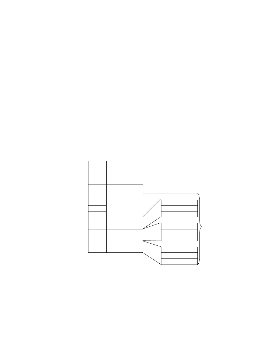
- 94 -
(3) WAVE Form Audio File Format
The WAVE Form is one kind of RIFF form. It is a file for handling digitized sound data. The form type is WAVE, in
upper-case letters.
The file extension for a WAVE Form Audio File is ".WAV ".
The data structure of the WAVE Form Audio File format is shown in Fig. 32.
As is evident from Fig. 32, the chunk data (ckData [ckSize]) of a RIFF chunk generally consists of the
formType ("WAVE"), fmt-ck (format chunk), fact-ck (fact chunk), and data-ck (data chunk). fmt-ck and data-ck are
mandatory chunks, but fact-ck may be mandatory or not, depending on the format type (audio coding format) of the
WAVE Form.
In addition to these, optional sub-chunks may be recorded and can store various attribute information. These
optional sub- chunks are not shown in Fig. 32.
Address Offset
Code
Meaning
Meaning
( Hex)
( Hex)
+00
52
+01
49
+02
46
+03
46
"RIFF"
( ckID)
+04
ckSize
( 4 Bytes )
+08
57
+09
41
"fmt"
+0A
56
ckSize( 4 Bytes)
+0B
45
"WAVE"
( formType)
ckData[ckSize]
+0C
:
fmt - ck
"fact"
:
ckSize( 4 Bytes )
:
fact- ck
ckData [ckSize]
ckData
[ckSize] of
RIFF
chunk
data- ck
"data"
ckSize( 4 Bytes )
ckData [ckSize]
Fig. 32 Data Structure of the WAVE Form Audio File Format

- 95 -
<fmt - ck>
fmt-ck (format chunk) contains format information designating the format of audio data included in the data-ck (data
chunk) described later below. The ckID (chunk ID) of fmt-ck is "fmt."
"fmt " is 3 characters long, so a blank character (20.H) goes at the end.
fmt -ck is mandatory and must always be recorded before data-ck.
Since fmt-ck has the chunk structure, ckSize and ckData[ckSize] are included as its members; but the contents of the
ckData depend on the format type (audio coding format). This ckData consists of the structure given in Equation 2,
and the byte array given in Equation 3.
struct{
unsigned int wFormatTag;
// Format type
unsigned int nChannels;
// Number of channels
unsigned long nSamplesPerSec;
// Sampling rate
unsignrd long nAvgBytesPerSec;
// Average bytes per second
unsigned int nBlockAlign;
// Block alignment
unsigned int wBitsPerSample;
// Bits per sample
unsigned int cbSize;
// Additional bytes
} WAVEFORMATEX;
- - -[Equation 2]
unsigned char extByte[cbSize];
// Additional byte array
- - -[Equation 3]

- 96 -
The meaning of each member of the format information is given in Table 23.
Table 23 Format Information Members
Member
Description
wFormatTag
An unsigned 16-bit integer indicating the format type (audio coding format) of the
WAVE Form. Typical format types are given below.
PCM (Pulse Code Modulation) format: 0001 .H
µ
- Law format ( ITU- T G.711 ): 0007.H
IMA- ADPCM (DVI- ADPCM) format: 0011 .H
nChannels
An unsigned 16-bit integer indicating the number of channels. Monaural is 1 and
stereo is 2.
nSamplesPerSec
An unsigned 32- bit integer indicating the sampling rate (samples per second). Audio
is played in each channel at this rate.
In PCM format the common values of this member are 8.0kHz, 11.025kHz,
22.05kHz, and 44.1kHz.
nAvgBytesPerSec
An unsigned 32- bit integer indicating the average bytes per second, a value
transferred to the data in data- ck.
In PCM format, nAvgBytesPerSec is equivalent to the equation below.
nChannels * wBitsPerSample /8
nBlockAlign
An unsigned 16-bit integer indicating the (byte unit) block alignment in data-ck. In
PCM format, nBlockAlign is equivalent to the equation below.
nChannels * wBitsPerSample/8
wBitsPerSample
An unsigned 16- bit integer indicating the bits per sample of each channel.
In PCM format, this value is 8 or 16.
In the case of compressed sound data, when this value cannot be defined it
becomes '0'.
cbSize
An unsigned 16-bit integer indicating the size (in bytes) of the additional format
information extByte[cbSize] appended after the WAVEFORMATEX structure. This
information is used to store attributes added in non- PCM formats. If additional
information is not needed, it becomes '0'.
In PCM format, this member is not needed (the cbSize field itself is not necessary).
extByte[cbSize]
A byte array representing the additional format information appended after the
WAVEFORMATEX structure.
The meaning of this information depends on the format type. If the value of cbSize is
0, this field does not exist.
In PCM format, both the cbSize field and extByte[cbSize] field are unnecessary.
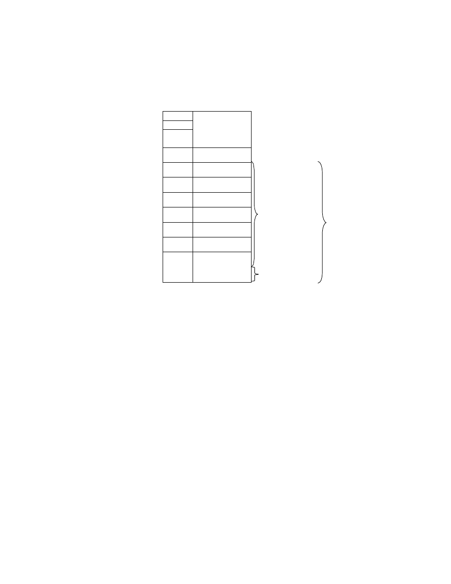
- 97 -
The fmt -ck structure can be illustrated as in Fig. 33.
Address Offset
Code
Meaning
( Hex)
(Hex)
+00
66
+01
6D
+02
74
+03
20
"fmt"
(ckID)
+04
ckSize
( 4 Bytes )
+08
wformatTag
( 2 Bytes )
+0A
nChannels
( 2 Bytes )
+0C
nSamplesPerSec
( 4 Bytes )
+10
nAvgBytesPerSec
( 4 Bytes )
+14
nBlockAlign
( 2 Bytes )
+16
wBitsPerSample
( 2 Bytes )
+18
cbsize
( 2 Bytes )
WAVEFORMATEX
Structure
( 18 Bytes)
ckData[ck Size]
of fmt - ck
+1A
extByte[cbSize]
Addition al Byte
Arrays
Fig. 33 fmt -ck Structure
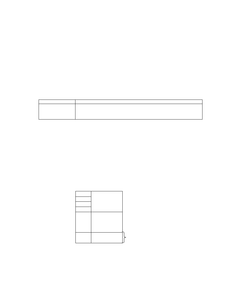
- 98 -
<fact- ck>
fact-ck (fact chunk) is used to store file -dependent information relating to the WAVE file contents. The ckID (chunk
ID) of fact-ck is "fact".
It is assumed that fact-ck will be extended in the future to store information needed by WAVE files at that time, but
currently only one information member is defined.
The information that can be stored in fact-ck at the present time is defined in [Equation 4].
unsigned long dwSampleLength;
// Sample length - - - [Equation 4]
Table 24 fact- ck Member
Member
Description
dwSampleLength
An unsigned 32-bit integer indicating the number of audio data samples (sample
length).
When this information is combined with nSamplePerSec in fmt-ck, the data length
can be expressed in seconds (recording time).
Since the only information defined presently is dwSampleLength, the value of ckSize (chunk Size) for fact-ck is
'00000004.H'; but ckSize may change in the future as information is added (in which case it will be larger than
'00000004.H'). Programs must be able to skip over fields they cannot Interoperability and go on to process the next
chunk. For this reason the capability of correctly reading the value of ckSize is a necessary requirement.
The structure of fact-ck is illustrated in Fig. 34. The value of ckSize is fixed at '00000004.H' (this value is used in
Write processing).
Address Offset
Code
Meaning
( Hex)
( Hex)
+00
66
+01
61
+02
63
+03
74
"fact"
( ckID)
+04
04
+05
00
+06
00
+07
00
00000004.H
( ckSize)
+08
dwSampleLength
( 4 Bytes )
ckData[ck Size]
Fig. 34 fact-ck Structure
<data- ck>
data-ck (data chunk) is a chunk for storing audio data. Its ckID (chunk ID) is "data".

- 99 -
The ckData (chunk Data) of data-ck consists of the audio data only. In some cases the chunk is filled out with
padding bytes.
The audio data is coded based on the format type. The information in fmt-ck is used when the audio data is played
back.
The ckSize (chunk Size) of data-ck is the size of the coded audio data only. The structure of data-ck is illustrated in
Fig. 35.
Address Offset
Code
Meaning
( Hex)
(Hex)
+00
64
+01
61
+02
74
+03
61
"data"
(ckID)
+04
ckSize
( 4 Bytes )
Size of audio data
+08
ckData[ckSize]
Coded audio data
Fig. 35 data -ck Structure
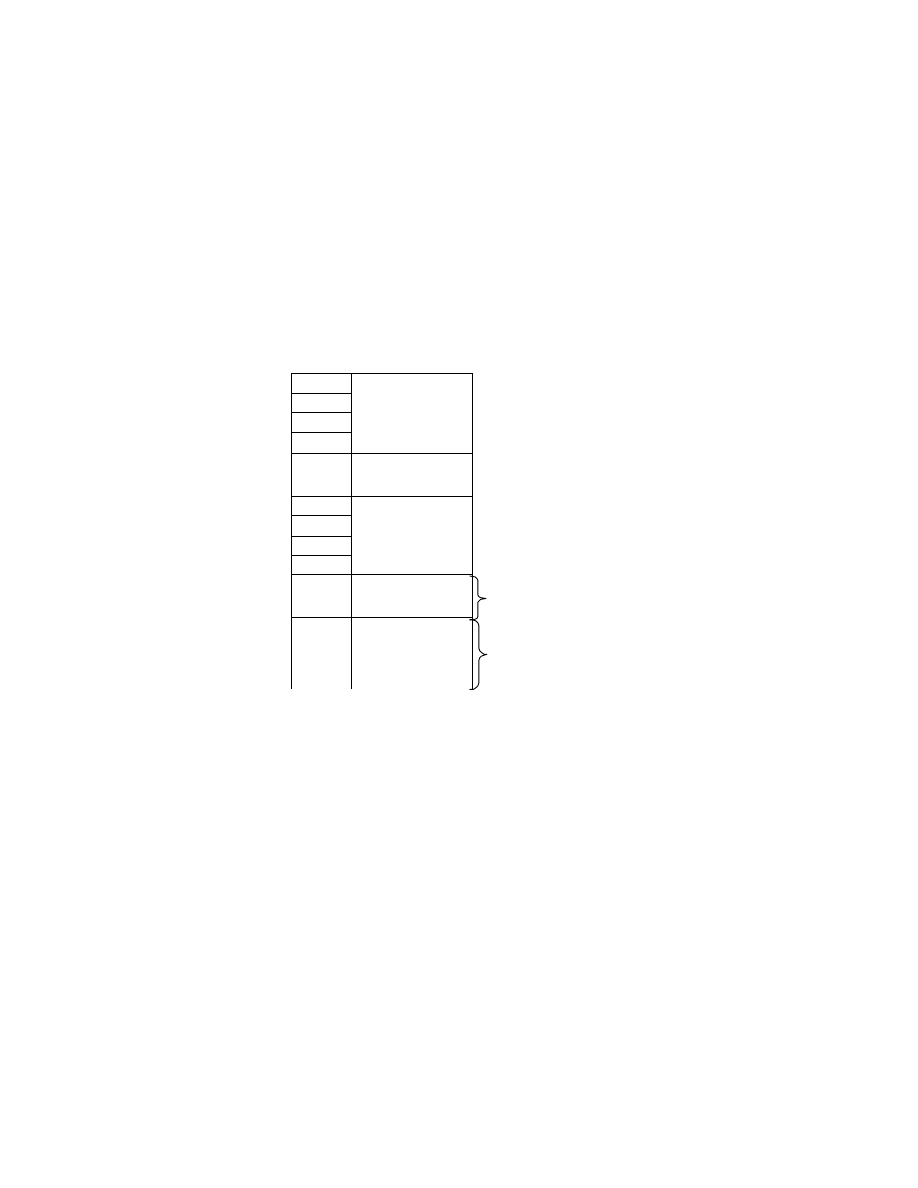
- 100 -
3.5.2. Basic Structure of PCM Audio Data
PCM audio data has linear quantization (A/D conversion) characteristics, and is not encoded for compression. It
therefore does not need to be decompressed for playback, but can simply be played by reading it directly.
The basic structure of audio data when the format type is PCM (Pulse Code Modulation) format is shown in Fig.
36.
Address Offset
Code
Meaning
( Hex)
( Hex)
+00
52
+01
49
+02
46
+03
46
"RIFF"
( ckID)
+04
ckSize
( 4 Bytes)
+08
57
+09
41
+0A
56
+0B
45
"WAVE"
( formType)
+0C
fmt - ck
( 24 Bytes)
PCM format information
( size is 24 bytes fixed)
+24
data- ck
PCM format audio data
Fig. 36 Basic Structure of PCM Format

- 101 -
The specific values stored in fmt -ck in the case of PCM format are as shown in Table 25.
Table 25 PCM Format fmt- ck Information
PCM ( Pulse Code Modulation) Format
Members
Code
ckSize ( fmt -ck)
00000010.H (16 Bytes, since cbSize is unnecessary)
wFormatTag
0001.H (PCM format )
nChannels
The values of each mode are as follows.
0001.H (monaural ) or 0002.H (stereo)
nSamplesPerSec
The values of each mode are as follows.
00001F40.H (8 .0 kHz)
00002B11.H (11 .025 kHz)
00005622.H (22.05 kHz)
0000AC44.H (44.10 kHz)
nAvgBytesPerSec
The values of each mode are as follows.
00001F40.H (8.0 kHz, 8- bit monaural )
00003E80.H (8.0 kHz, 8- bit stereo)
00003E80.H (8.0 kHz, 16 -bit monaural )
00007D00.H (8.0 kHz, 16-bit stereo)
00002B11.H (11.025 kHz, 8- bit monaural)
00005622.H (11.025 kHz, 8- bit stereo)
00005622.H (11.025 kHz, 16- bit monaural )
0000AC44.H (11.025 kHz, 16 - bit stereo)
00005622.H (22.05 kHz, 8- bit monaural )
0000AC44.H (22.05 kHz, 8 - bit stereo)
0000AC44.H (22.05 kHz, 16-bit monaural )
00015888.H (22.05 kHz, 16 - bit stereo)
0000AC44.H (44.10 kHz, 8 - bit monaural )
00015888.H (44.10 kHz, 8- bit stereo)
00015888.H (44.10 kHz, 16 - bit monaural)
0002B110.H (44.10 kHz, 16 - bit stereo)
Definition: nSamplesPerSec * nBlockAlign
nBlockAlign
The values of each mode are as follows.
0001.H (8 - bit monaural )
0002.H (8 - bit stereo)
0002.H (16-bit monaural )
0004.H (16-bit stereo)
Definition: nChannels * wBitsPerSample/8
wBitsPerSample
The values of each mode are as follows.
0008.H (8 bit) or 0010.H (16bit)
cbSize
Not used
extByte[cbSize]
Not used
- 102 -
In the case of PCM format audio data, the data format of each sample is 8-bit or 16-bit integer. These sample data
formats and their values are given in Table 26.
Table 26 Sample Data Formats and Values
Sample Size
Data Format
Minimum
Interoperability
Maximum
8-bit PCM
Unsigned
Integer
0 ( 00.H)
128 ( 80.H)
255 ( FF.H)
16- bit PCM
Signed Integer
-32768 ( 8000.H)
0 ( 0000.H)
32767 (7FFF.H)
The PCM format audio data contained in data-ck is packed as shown in Fig. 37. Here the left-hand byte stores the
lower address and the right -hand byte holds the upper address.
8- bit monaural PCM
Sample 0
Sample 1
Sample 2
Sample 3
Channel 0
Channel 0
Channel 0
Channel 0
Byte 0
Byte 1
Byte 2
Byte 3
8- bit stereo PCM
Sample 0
Sample 1
Channel 0
(left)
Channel 1
(right)
Channel 0
(left)
Channel 1
(right)
Byte 0
Byte 1
Byte 2
Byte 3
16- bit monaural PCM
Sample 0
Sample 1
Channel 0
Lower Byte
Channel 0
Upper Byte
Channel 0
Lower Byte
Channel 0
Upper Byte
Byte 0
Byte 1
Byte 2
Byte 3
16- bit stereo PCM
Sample 0
Channel 0
(left)
Lower Byte
Channel 0
(left)
Upper Byte
Channel 1
(right)
Lower Byte
Channel 1
(right)
Upper Byte
Byte 0
Byte 1
Byte 2
Byte 3
Fig. 37 Packing of PCM Audio Data
- 103 -
3.5.3. Basic Structure of
µ
-Law Audio Data
Each of the audio data samples of
µ
- Law audio data has nonlinear (logarithmic) quantization characteristics. For this
reason 16 bits of data can be represented in an 8-bit size. In playback, either the data is first converted to linear
16-bit data and then put through a linear D/A converter, or else the analog signal is derived by going through an
8-bit nonlinear D/A converter with characteristics opposite the
µ
-Law quantization characteristics. Details of the
nonlinear quantization characteristics and of the conversion between 8-bit
µ
- Law data and 16-bit linear data are
given in the ITU-T G.711
v i i i
standard.
When the format type is
µ
-Law (ITU- T G.711) format, the basic structure is expressed as in Fig. 38.
The two differences from PCM format are the larger size of fmt-ck (the cbSize file exists) and the existence of
fact-ck.
Address Offset
Code
Meaning
( Hex)
(Hex)
+00
52
+01
49
+02
46
+03
46
"RIFF"
(ckID)
+04
ckSize
( 4 Bytes )
+08
57
+09
41
+0A
56
+0B
45
"WAVE"
(formType)
+0C
fmt- ck
(26 Bytes)
µ
-Law format information (size is
26 bytes fixed)
+26
fact- ck
(12 Bytes)
Samples per channel-unit block
(
µ
-Law format)
+32
data- ck
PCM format audio data
Fig. 38 Basic Structure of
µ
- Law Format
- 104 -
The specific values of the information stored in fmt-ck and fact-ck in the case of the
µ
-Law format are given in
Table 27.
Table 27 fmt - ck and fact- ck Information in
µ
-Law Format
µ
- Law ( ITU- T G.711 ) Format
Members
Code
ckSize( fmt -ck)
00000012.H ( 18 bytes, WAVEFORMATEX only)
wFormatTag
0007.H (
µ
- Law format)
nChannels
The values of each mode are as follows.
0001.H (monaural ) or 0002.H (stereo)
nSamplesPerSec
00001F40.H (8 .0kHz)
nAvgBytesPerSec
The values of each mode are as follows.
0000 1F40.H (8.0kHz, 8-bit monaural )
00003E80.H (8.0kHz, 8-bit stereo)
Definition: nSamplesPerSec * nBlockAlign
nBlockAlign
The values of each mode are as follows.
0001.H (8bit monaural)
0002.H (8bit stereo )
Definition: nChannels * wBitsPerSample/8
wBitsPerSample
0008.H (8bit)
cbSize
0000.H (extByte[cbSize] does not exist )
extByte[cbSize]
Not used
dwSampleLength
It is recommended that the actual number of samples that can be
played be recorded here.
Definition: ( ckSize_of_data-ck) / nBlockAlign
The
µ
-Law audio data contained in data-ck is packed as shown in Fig. 39. Here the left- hand byte stores the lower
address and the right- hand byte holds the upper address.
µ
- Law monaural
Sample 0
Sample 1
Sample 2
Sample 3
Channel 0
Channel 0
Channel 0
Channel 0
Byte 0
Byte 1
Byte 2
Byte 3
µ
- Law stereo
Sample 0
Sample 1
Channel 0
(left)
Channel 1
(right)
Channel 0
(left)
Channel 1
(right)
Byte 0
Byte 1
Byte 2
Byte 3
Fig. 39 Packing of
µ
- Law Audio Data
- 105 -
3.5.4. Basic Structure of IMA-ADPCM Audio Data
IMA- ADPCM audio data is 4-bit data obtained by compressing 16-bit linear PCM audio data. IMA-ADPCM, as
seen in its other name DVI-ADPCM, uses a compression algorithm originally developed by the Intel DVI Group
(DVI: Digital Video Interoperability). It was later adopted by the IMA (Interoperability Multimedia Association) as
a standard audio data format.
Details of the IMA- ADPCM algorithm are given in the IMA Digital Audio Doc- Pac
xvii
and other documents.
When the format type is IMA- ADPCM (DVI-ADPCM), the basic structure is as shown in Fig. 40.
A fact -ck is recorded as with the
µ
-Law format, but a difference from that format is the larger fmt-ck size (in
addition to a cbSize field there is a wSamplesPerBlock field).
Address Offset
Code
Meaning
( Hex)
(Hex)
+00
52
+01
49
+02
46
+03
46
"RIFF"
(ckID)
+04
ckSize
( 4 Bytes )
+08
57
+09
41
+0A
56
+0B
45
"WAVE"
(formType)
+0C
fmt- ck
(28 Bytes)
IMA- ADPCM format information (size is 28
bytes fixed)
+28
fact- ck
(12 Bytes)
Samples per channel -unit block
(IMA-ADPCM format)
+34
data- ck
PCM format audio data
Fig. 40 Basic Structure of IMA -ADPCM Format

- 106 -
The specific values of the information stored in fmt-ck and fact-ck in the case of the IMA- ADPCM format are given
in Table 28 and Table 29.
Table 28 IMA- ADPCM Format fmt -ck and fact-ck Information ( 1)
IMA- ADPCM (DVI-ADPCM) Format
Members
Code
ckSize( fmt -ck)
00000014.H (20 bytes)
wFormatTag
0011.H (IMA- ADPCM format )
nChannels
0001.H (monaural ) or 0002.H (stereo)
nSamplesPerSec
The values of each mode are as follows.
00001F40.H (8 .0 kHz)
00002B11.H (11.025 Hz)
00005622.H (22.050 Hz)
0000AC44.H (44.10 Hz)
nAvgBytesPerSec
The values of each mode are as follows.
00000FD7.H (8.0 kHz, 4 - bit monaural )
00001FAE.H (8.0 kHz, 4 - bit stereo)
000015D4.H (11.025 kHz, 4-bi t monaural)
00002BA9.H (11.025 kHz, 4-bit stereo)
00002B5C.H (22.05 kHz, 4 - bit monaural)
000056B9.H (22.05 kHz, 4- bit stereo)
0000566D.H (44.10 kHz, 4 - bit monaural )
0000ACDB.H (44.10 kHz, 4 - bit stereo)
Definition: nSamplesPerSec*nBlockAlign/wSamplesPerBlock
nBlockAlign
The values of each mode are as follows.
0100.H (8.0 kHz, 4- bit monaural )
0200.H (8.0 kHz, 4- bit stereo)
0100.H (11.025 kHz, 4- bit monaural)
0200.H (11.025 kHz, 4- bit stereo)
0200.H (22.05 kHz, 4- bit monaural )
0400.H (22.05 kHz, 4- bit stereo)
0400.H (44.10 kHz, 4- bit monaural )
0800.H (44.10 kHz, 4- bit stereo)
Although the definition is ( N+1) * 4 * nChannels, the use of
256 * nChannels * max ( 1,nSamplesPerSec / 11.025kHz )
is recommended.
wBitsPerSample
0004.H (4 bits)
cbSize
0002.H

- 107 -
Table 29 IMA- ADPCM Format fmt - ck and fact- ck Information ( 2)
IMA-ADPCM ( DVI- ADPCM) Format
extByte[cbSize]
The values of each mode are as follows.
01F9.H ( 8.0 kHz, 4 -bit monaural )
01F9.H ( 8.0 kHz, 4 -bit stereo)
01F9.H ( 11.025 kHz, 4- bit monaural)
01F9.H ( 11.025 kHz, 4 bit stereo)
03F9.H ( 22.05 kHz, 4- bit monaural )
03F9.H ( 22.05 kHz, 4- bit stereo)
07F9.H ( 44.10 kHz, 4- bit monaural )
07F9.H ( 44.10 kHz, 4- bit stereo)
If the definition is, wSamplesPerBlock (an unsigned 16- bit integer
indicating the samples per channel-unit block), and
X = (nBlockAlign - ( 4 * nChannels) )* 8
Y = wBitsPerSample * nChannels
then,
wSamplesPerBlock =(X/Y) +1
dwSampleLength
It is recommended that the actual number of samples that can be
played back be recorded.
The definition is as follows.
If X = ckSize_of_data-ck/nBlockAlign
then,
dwSampleLength = ( X+1) * wSamplesPerBlock
The IMA- ADPCM audio data contained in data-ck is packed as shown in Fig. 41, Fig. 42, and Fig. 43 when it is
recorded.
A feature of this format is the existence of a header at the start of each block. The header records the initial sample
value for that block and a step (quantization table) index. The audio data in each channel is independent, so the
number of header words is the same as the number of channels.
A header word consists of 4 bytes, and is defined as in [equation 5]. The existence of a header means IMA- ADPCM
audio data can be played from any block. In other words, random access is possible on a per- block basis.
In Fig. 41 to Fig. 43, the left- hand byte stores the lower address and the right-hand byte holds the upper address.
typedef struct {
signed int iSamp0;
// Initial sample value of the block
unsigned char bStepTableIndex;
// Step table index
unsigned char bReserved;
// reserved byte
} IMA_ADPCMBLOCKHEADER;
- - - [Equation 5]
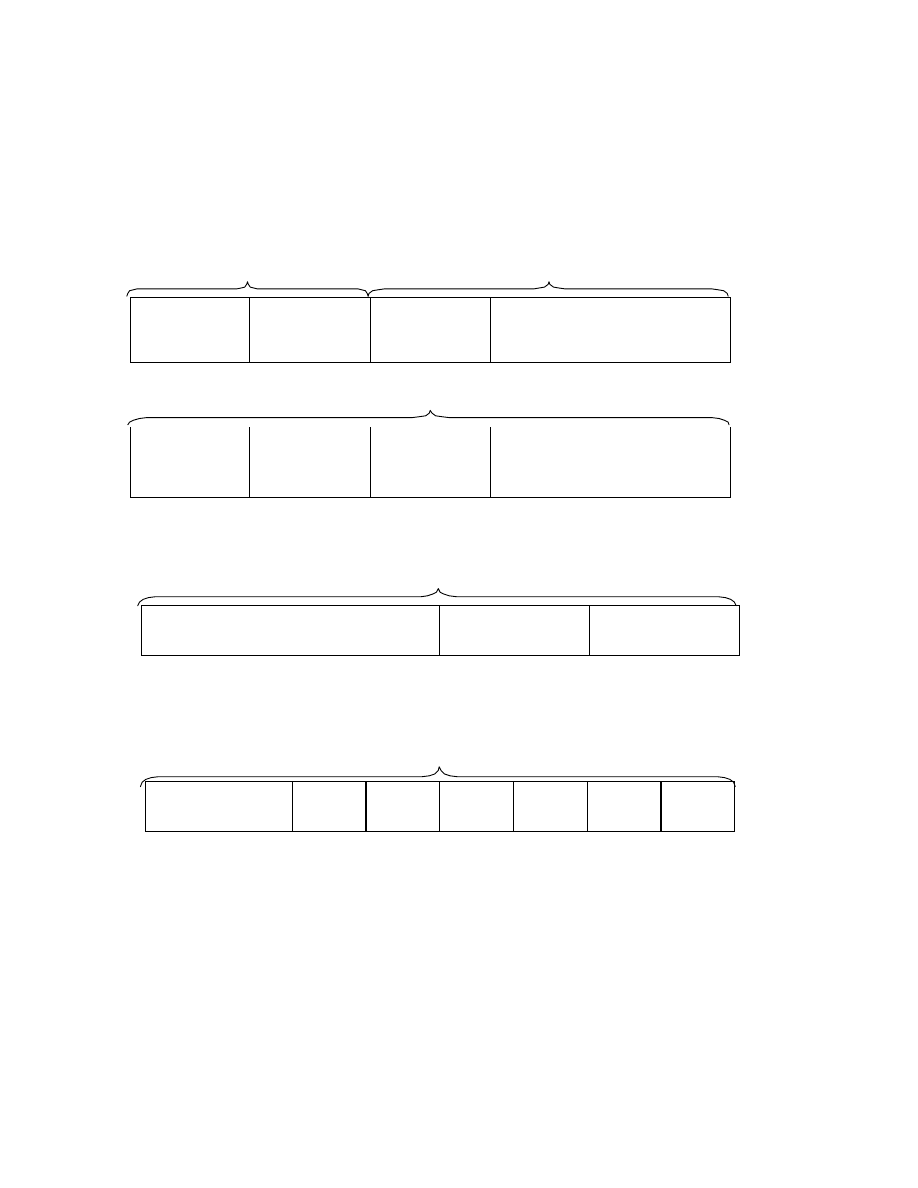
- 108 -
In Fig. 41 to Fig. 43, N, M, and P have the following significance.
N = (nBlockAlign/ ( 4*nChannels) ) - 1
- - -[Equation 6]
M = 0, 1, 2, 3, ....... , N-1
- - -[Equation 7]
P = ( M * 8 ) + 1
- - -[Equation 8]
Header
Data
Header Word
Channel 0
(left)
Header Word
Channel 1
(right)
Data Word 0
Channel 0
(left)
Data Word 0
Channel 1
(right)
........
Data ( total = N words/Channel )
Data Word M
Channel 0
(left)
Data Word M
Channel 1
(right)
........
Data Word N- 1
Channel 0
(left)
Data Word N- 1
Channel 1
(right)
Fig. 41 Packing of IMA -ADPCM Audio Data
Header Word ( 4 Bytes )
Sample 0
Lower Byte
Sample 0
Upper Byte
Step Table Index
Reserved Byte
Byte 0
Byte 1
Byte 2
Byte 3
Fig. 42 Header Word of IMA -ADPCM Audio Data
Data Word M ( 4 Bytes )
Sample P
LSB MSB
P+1
LSB MSB
P+2
LSB MSB
P+3
LSB MSB
P+4
LSB MSB
P+5
LSB MSB
P+6
LSB MSB
P+7
LSB MSB
Byte 0
Byte 1
Byte 2
Byte 3
Fig. 43 Data Word M of IMA -ADPCM Audio Data

- 109 -
3.6. Chunks Used
The chunks used in Exif audio files are described here.
3.6.1. WAVE Form Audio File Basic Chunks
The basic chunks of a WAVE Form Audio File, as is evident from the basic structure of the WAVE file shown in Fig.
32, are the four below.
•
RIFF chunk
•
fmt chunk
•
fact chunk
•
data chunk
[Additional Explanation]
•
The fmt chunk, fact chunk and data chunk are sub-chunks of the RIFF chunk. A WAVE file consists of one
RIFF chunk, with specific information recorded in the sub -chunks.
•
Only when the form type is PCM (Pulse Code Modulation) format, the fact chunk is unnecessary. With
non-PCM formats such as
µ
- Law and IMA- ADPCM, it is mandatory, which is why fact-ck is included in the
basic chunks here.
•
It is possible to add other optional sub-chunks as well.
•
At the head of the chunk data (ckData) of the RIFF chunk there is a form type called "WAVE".

- 110 -
3.6.2. LIST Chunk and INFO List
A WAVE form and other RIFF forms store a variety of information in sub-chunks of the RIFF chunk. These
sub-chunks in many cases are specific to each form type; but there are also general-purpose chunks for storing
additional information regardless of the data specified for a given form type.
One of these general- purpose chunks is the LIST chunk. Here the use of the LIST chunk is explained.
(1) LIST Chunk
The LIST chunk is a general-purpose chunk that can be used with the files of many different form types. The LIST
chunk is a pre- registered general-purpose chunk, so its ckID (chunk ID) is written in upper-case letters.
Included in the LIST chunk is a sub- chunk list (series of sub- chunks) and sequence designation.
The LIST chunk ckData (chunk data) consis ts of a four-character code at the beginning called a listType (list type),
followed by the sub-chunk list.
This structure resembles that of the RIFF chunk, but the LIST chunk is always farther down the hierarchy than the
RIFF chunk.
The list type is used to identify the list contents. For this reason there are list types that are used only with certain
form types. If a list type is encountered that cannot be Interoperability, that LIST chunk can be ignored.
The list type must be registered. A general-purpose list type that is registered and can be used with various form
types is written in all upper-case letters.
A list type that can be used only with a specific form type is written in lower-case letters.
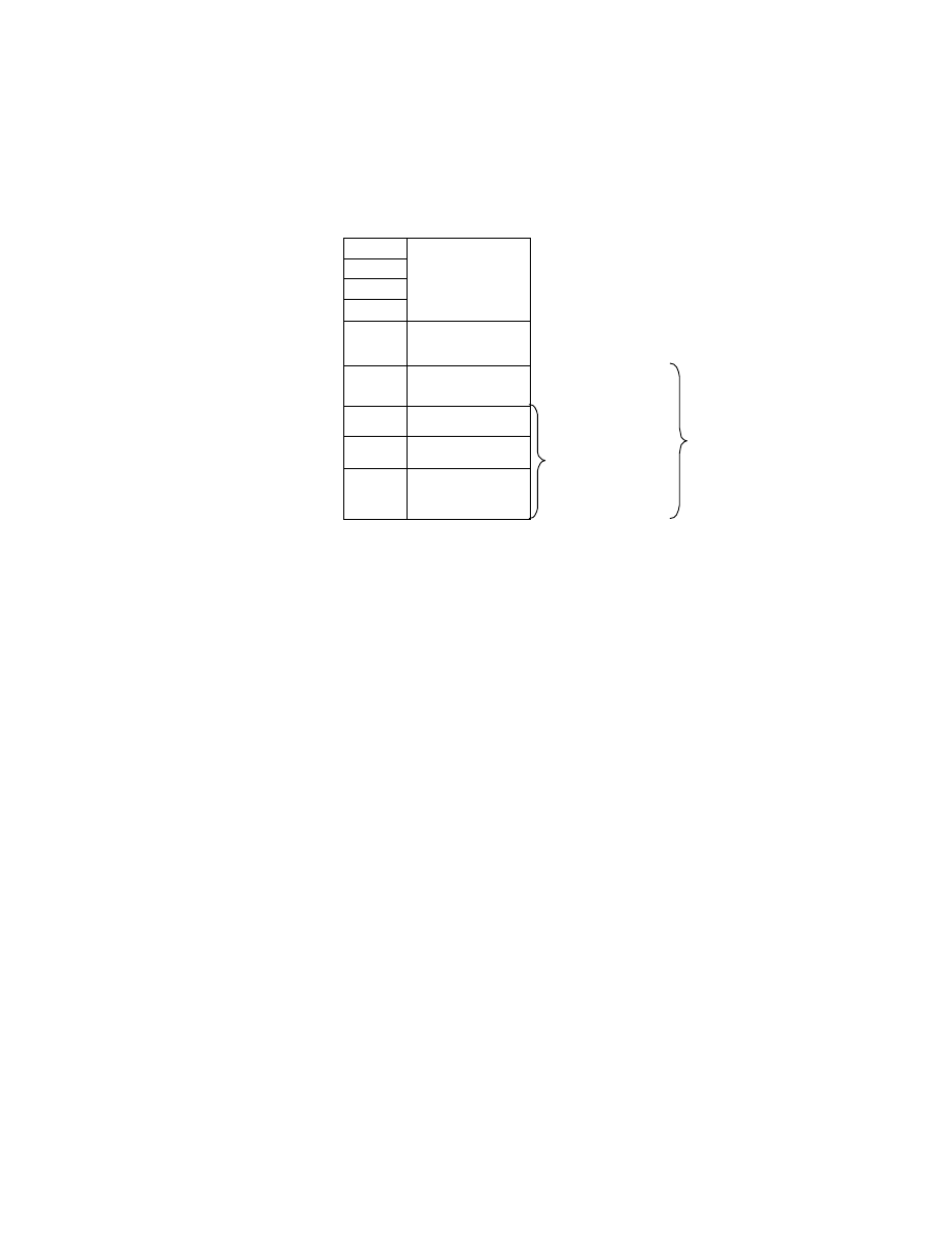
- 111 -
The LIST chunk structure is illustrated in Fig. 44.
Address Offset
Code
Meaning
( Hex)
(Hex)
+00
4C
+01
49
+02
53
+03
54
"LIST"
(ckID)
+04
ckSize
( 4 Bytes )
+08
listType
( 4 Bytes )
+0C
Subchunk 1
:
:
Subchunk 2
:
:
:
:
:
:
Sub- chunk list
ckData [ckSize] of
LIST chunk
Fig. 44 LIST Chunk Structure
(2) INFO List
An "INFO list " is a LIST chunk having the registered, general- purpose listType "INFO".
The need for information such as title, copyright and comments is similar in each of the form types. The INFO list is
used for storing these kinds of information.
The information itself in an INFO list is stored in the sub-chunk lists. These sub-chunks use only pre-registered,
general- purpose chunks, described later below.
The INFO list information is supplementary and has no influence on the Interoperability of the main data, such as
WAVE form audio data. It can therefore be skipped without problem. If an unknown chunk is included on the INFO
list, as when a new chunk has been defined, it is to be ignored.

- 112 -
The INFO list chunks currently defined are given in Table 30. These pre-registered chunks are stored as ASCII text
strings terminated by NULL (the final byte is '00.H').
Table 30 INFO List Chunks
Channel ID
Description
IARL
Archival Location. Indicates where the subject of the file is archived.
IART
Artist. Lists the artist of the original subject of the file.
ICMS
Commi ssioned. Lists the name of the person or organization that commissioned the
subject of the file.
ICMT
Comments. Provides general comments about the file or the subject of the file.
ICOP
Copyright. Records the copyright information for the file.
ICRD
Creation date. Indicates the date the subject of the file was created.
ICRP
Cropped. Indicates whether an image has been cropped
IDIM
Dimensions. Specifies the size of the original subject of the file.
IDPI
Dots Per Inch. Stores the dots per inch (DPI) setting of the digitizer used to produce
the file.
IENG
Engineer. Stores the name of the engineer who worked on the file.
IGNR
Genre. Describes the genre of the original work.
IKEY
Keywords. Provides a list of keywords that refer to the file or subject of the file.
ILGT
Lightness. Describes the changes in lightness settings on the digitizer required to
produce the file.
IMED
Medium. Describes the original subject of the file, such as, "computer image,"
"drawing," "lithograph," and so forth.
INAM
Name. Stores the title of the subject of the file.
IPLT
Palette Setting. Specifies the number of colors requested when digitizing an image.
IPRD
Product. Specifies the name of the title the file was originally intended for, such as
"Encyclopedia of Pacific Northwest Geography."
ISBJ
Subject. Describes the file contents, such as "Aerial view of Seattle."
ISFT
Software. Identifies the name of the software package used to create the file.
ISHP
Sharpness. Identifies the changes in sharpness for the digitizer required to produce
the file.
ISRC
Source. Identifies the name of the person or organization who supplied the original
subject of the file.
ISRF
Source Form. Identifies the original form of the material that was digitized, such as
"slide," "paper," "map," and so forth.
ITCH
Technician. Identifies the technician who digitized the subject file.
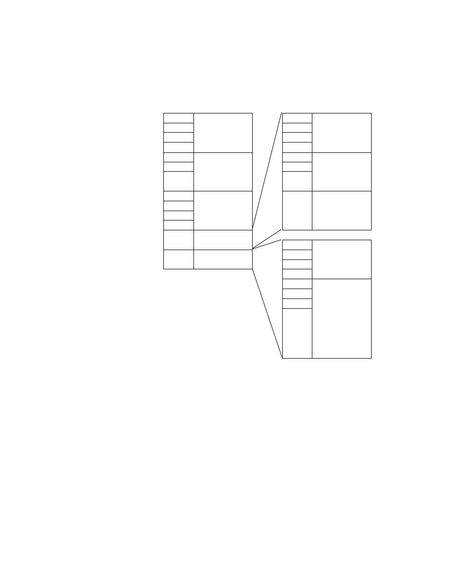
- 113 -
A typical INFO list is shown in Fig. 45.
Address Offset
Code
Meaning
Code
Meaning
( Hex)
(Hex)
( Hex)
+00
4C
49
+01
49
4E
+02
53
41
+03
54
"LIST"
(ckID)
4D
"INAM"
( ckID)
+04
40
0A
+05
00
00
+06
00
00
+07
00
00000040.H
( ckSize)
00
0000000A.H
(ckSize)
+08
49
+09
4E
+OA
46
+OB
4F
"INFO"
( listType )
"Two Trees"Z
(ckData)
+OC
INAM- ck
(18 Bytes)
49
4E
+1E
ICMT - ck
(42 Bytes)
41
4D
"ICMT"
( ckID)
21
00
00
00
00000021.H
(ckSize)
"A picture for
the o pening
screen"Z
(ckData)
Fig. 45 Typical INFO List
The following points need to be observed in using the INFO list . They are explained in reference to Fig. 45.
•
The 'Z' at the end of the text string information in the INAM and ICMT chunks means NULL termination.
The actual code appended is '00.H'.
•
The chunk data (ckData) in each chunk must be an even number of bytes. If the data itself is an odd number
of bytes, it must be padded by one additional byte.
•
In the example in Fig. 45, the ICMT chunk has 33 bytes of information including the NULL termination, so a
padding byte '00.H' must be appended. No padding is necessary with the INAM chunk information, since the
size including NULL termination is 10 bytes.
•
The value of the chunk size (ckSize) of the ICMT chunk does not include the padding byte. However, the
chunk size of the LIST chunk that is its parent chunk must include the padding bytes in the sub-chunks. If this

- 114 -
rule is not observed, it will not be possible to determine the start addr ess of a chunk following after this LIST
chunk.
(3) INFO List used by Exif audio files
The INFO list used with Exif audio files is as follows.
The chunks that can be included on the INFO list are those given in Table 30; but of these, only the following are
used with Exif audio files.
[Chunks Used with Exif]
INAM
Records the title of the Exif audio file. The title is written in an ASCII string and terminated with NULL. Recording
this information is optional.
Ex.) "Exif Audio File Example"Z
IGNR
Records the genre of the Exif audio file subject. The genre name is written in an ASCII string and terminated with
NULL. Recording this information is optional.
Ex.) "narration"Z
ICRD
Records the date the Exif audio file was created. It is written as a fixed- length ASCII string, in the format
year- month- day. That is, the year, month, and day are separated by a hyphen. The year is four digits, while month
and day are two digits each. If the number of the month or the day is less than 10, the first digit is 0. The order must
be year-month- day. Since this information is written as an ASCII string, it must be terminated with NULL. This
chunk is fixed- length (the chunk data is 11 bytes, and a padding byte is added to make it an even byte number).
Recording this information is optional.
Ex.) "1997 - 04-08"Z (Note: =April 8, 1997)
ICMT
Records a general comment on the Exif audio file or its subject. Comments are written in ASCII text terminated
with NULL. If there are two or more comments, each statement ends with a period. A carriage return or line feed
character must not be used. Recording this information is optional.
Ex.) "Recorded by Digital Still Camera"Z
IART
Records the name of the Exif audio file creator. The name is written in an ASCII string and terminated with NULL.

- 115 -
Recording this information is optional.
Ex.) "Taro Yamada"Z
ICOP
Records copyright information for the Exif audio file. The copyright is written in ASCII text and terminated with
NULL. In case of multiple copyright information, each is separated by a semicolon followed by one blank space
(20.H). Recording this information is optional.
Ex.) "Copyright Exif Corporation 1997. "Z
[Notes and Additional Information]
•
A camera shall not record chunks other than those listed above.
•
If a camera encounters an unknown chunk when reading the INFO list, it shall skip that chunk. It is possible
that the INFO list will be expanded in the future, and this provision ensures that compatibility will be
maintained.
•
Information shall be recorded in accord with the general INFO list stipulations.
•
All the information on the INFO list is optional, and does not have to be recorded.
•
The INFO list used for Exif audio files consists of pre-registered, general-purpose chunks only, which means
this information can be read by commercial "RIFF Form Reader" software (such as the utility software
provided with Windows
™
).

- 116 -
3.6.3. Chunks for Attribute Information Specific to Exif Audio Files
Recording of attribute information specific to Exif audio files is done as follows.
Exif- specific attributes are those not defined for ordinary WAVE Form Audio Files but only for Exif audio files.
This is auxiliary information with no influence on Interoperability of the audio data itself. For this reason an Exif
audio file can still be compatible with a standard WAVE Form Audio File.
The attributes specific to Exif audio files are recorded as follows.
(1) LIST chunk is used.
The compatibility noted above is realized by using a pre-registered, general-purpose LIST chunk to record the
attribute information specific to Exif audio files. Since it can be used with all the LIST chunk form types, this chunk
can be put in the WAVE Form Audio File. The individual information is recorded in sub- chunks of the LIST chunk.
(2) A dedicated list type "exif" is defined.
The information in the LIST chunk is explicitly labeled as information specific to Exif audio files by defining a
dedicated list type. The following is used as this list type.
•
Dedicated Exif list type: "exif" (all lower-case letters)
The attributes specific to Exif audio files cannot be used in the WAVE Form Audio File format, so it is all written in
lower-case letters.
Hereafter, the notation "exif list" is used to mean the LIST chunk whose list type is exif.
(3) A dedicated chunk is defined for each of the attributes.
Since there are no corresponding existing chunks, a dedicated chunk is defined to record the attribute information
specific to Exif audio files. The information items and their chunks are described below.

- 117 -
[Information items and chunks]
ever
Records the version information (number) of this standard.
As with Exif image files, it is recorded in 4 bytes. The address bytes are recorded as A1, A2, B1, B2, starting with
the lowest number. A1 and A2 store the upper part of the standard version, with the lower part stored in B1 and B2.
A1, A2, B1 and B2 are ASCII numerals giving the version number, but NULL termination is unnecessary. This
chunk is mandatory.
On the conventions for version number updating, see section 3.2.
Ex.) "0200" (Note: =Version 2.00)
erel
Records information pointing to an Exif image file related to the Exif audio file recorded in this chunk. Recording
this information makes it possible for a camera or application software to map an image to sound during playback.
The relational information consists of the name of the corresponding Exif image file, given as an 8-character file
name plus 3-character extension in ASCII format. The path is not written. Stipulations on images are given in
section 2.6.5. File naming rules are covered in section 3.7.1.
The mapping of Exif image files and audio files is done in any of the three ways shown in Table 31. If multiple files
are mapped to one file as in [2] or [3] of Table 31, the above format is used to record just one destination file name.
If there are multiple destination files, the first recorded file is given.
In the case of [2] in Table 31, for the Exif audio file "SND00001.WAV" only "DSC00001.JPG" is given as the
related image file. When there are three Exif image files "DSC00001.JPG," "DSC00002.JPG" and
"DSC00003.JPG," the related Exif audio file name for each of them, "SND00001.WAV," is indicated. By combining
multiple relational information, a variety of playback possibilities can be supported. The me thod of using relational
information is left to the implementation on the playback side. Since this information is an ASCII character string, it
is terminated by NULL. If there is a related Exif image file, this chunk is mandatory.
Ex.) "DSC00001.JPG"Z
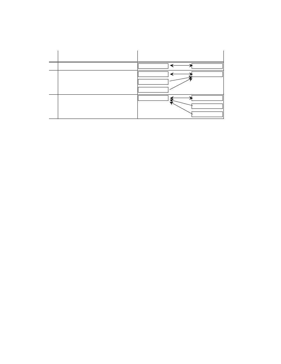
- 118 -
Table 31 Mapping between Image and Audio Files
Relationship
Exif Image File
Exif Audio File
[1]
1 to 1
DSC00001.JPG
SND00001.WAV
[2]
Many to 1
DSC00001.JPG
DSC00002.JPG
DSC00003.JPG
SND00001.WAV
[3]
1 to many
DSC00001.JPG
SND00001.WAV
SND00002.WAV
SND00003.WAV
etim
Records the time of Exif audio file creation. This is defined as the time the recording of audio data was started. Time
is expressed as a variable- length ASCII string. In order to conform as closely as possible to the Exif image file, time
is recorded in the format "hour:minute:second.subsecond," with a colon in between each time unit and a period
before the subsecond position.
Hour, minute and second are written as two digits each, with the first digit a zero if the value is one digit.
Subseconds can be expressed to any desired decimal place. If there is no subsecond information, the string ends with
a period only.
The order of time units is hour, minute, second, subsecond. The information is written as an ASCII string, so it must
be terminated with NULL. Recording this information is optional.
Ex.) "10:05:10.130"Z
ecor
Records the name of the manufacturer of the equipment on which the Exif audio file was created. The manufacturer
name is written in an ASCII string and terminated with NULL. Recording this information is optional.
Ex.) "Digital Still Camera Corporation "Z
emdl
Records the model name of the equipment on which the Exif audio file was created. The model name is written in an
ASCII string and terminated with NULL. Recording this information is optional.
Ex.) "DSCamera1000"Z
emnt
As with Exif image files, this chunk is used by the writer manufacturer to record design information, version history
and other maker-specific information. The contents and format of the information are up to each manufacturer.

- 119 -
Other manufacturers see this information only as a byte array of the size determined by the chunk size ( ckSize).
Recording this information is optional.
eucm
Records user comment information that cannot be recorded on, or is not suitable for, the INFO list. Basically this is
text information. Character code information is included so languages that do not use ASCII can be used here.
Recording this chunk is optional.
Recording of user comments is discussed below. The structure of the user comment chunk is shown in Fig. 46.
Address Offset
Code
Meaning
Meaning
( Hex)
(Hex)
+00
65
+01
75
+02
63
+03
6D
"eucm"
( ckID)
Character code
( 8 Bytes)
+04
ckSize
( 4 Bytes )
+08
ckData [ck Size]
(user comment)
User Comments
Fig. 46 Structure of User Comment Chunk
As seen in Fig. 46, the chunk data area storing the user comment starts with an 8-byte character code area, where
the character code is given. The rest of the chunk data area is the user comment area, used for writing comments.
The currently defined character codes are shown in Table 32. A registration system is used for character codes to
avoid duplication. When a character code is registered, a standard document is indicated in the reference column to
indicate the character format specification. If a character code is used for which there is no clear specification like
Shift- JIS in Japan, Undefined is designated.
The character code is written from the start of the character code area, and the unused portion is padded with NULL
('00.H'). In order to match the format of the actual comments in the user comment part to that of the Exif image file
UserComment tag, NULL termination is not used even if the comment is written in ASCII text. In accord with the
chunk specification, however, a padding byte ('00.H') is used if the chunk data is not an even number of bytes.
Table 32 Character Codes and Character Code Designation
Character Code
Code Designation ( 8 Bytes )
Reference
ASCII
41.H, 53.H, 43.H, 49.H, 49.H, 00.H, 00.H, 00.H
ITU- T T.50 IA5
x
JIS
4A.H, 49.H, 53.H, 00.H, 00.H, 00.H, 00.H, 00.H
JIS X0208- 1990
x i
Unicode
55.H, 4E.H, 49.H, 43.H, 4F. H, 44.H, 45.H, 00.H
Unicode Standard
xii
Undefined
00.H, 00.H, 00.H, 00.H, 00.H, 00.H, 00.H, 00.H
Undefined

- 120 -
[Notes and Additional Information]
•
The above chunks incorporated in exif list are used with a specific form type (' WAVE') and are therefore
written in all lower-case letters.
•
Only the ever chunk is mandatory; the others are optional. If an Exif image file related to an audio file exists,
the erel chunk is also mandatory.
•
When the exif list is read by a camera, information that cannot be recognized may be encountered, such as
the emnt chunk or an Undefined string in the eucm chunk. In that case the chunk is to be skipped.
•
An Exif reader and writer must conform to the stipulations for an ordinary LIST chunk.
•
A general-purpose RIFF Form Reader will ignore the exif list. A dedicated Exif reader is required for reading
the exif list.
•
Fig. 47 shows the exif list structure and a coding example. The ever chunk is mandatory and has a fixed
length (chunk data is 4 bytes). The erel chunk data is 13 bytes (odd), so a padding byte is added. The erel
chunk is also fixed length.
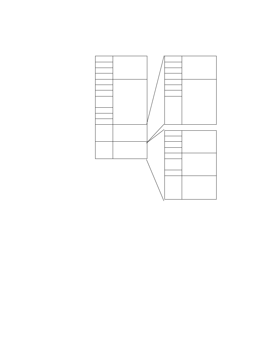
- 121 -
Address Offset
Code
Meaning
Code
Meaning
( Hex)
(Hex)
( Hex)
+00
4C
65
+01
49
76
+02
53
65
+03
54
"LIST"
(ckID)
72
"ever"
( ckID)
+04
26
04
+05
00
00
+06
00
00
+07
00
00000026.H
( ckSize)
00
0000000A.H
(ckSize)
+08
65
+09
78
+0A
69
+0B
66
"exif"
( listType )
"0200"
(ckData)
65
+0C
ever - ck
(12 Bytes)
72
65
6C
"erel"
( ckID)
+1E
erel- ck
(22 Bytes)
0D
00
00
00
000000D.H
(ckSize)
"DSC00001.JPG"
Z
(ckData)
Fig. 47 exif List Structure and Typical Coding

- 122 -
3.7. Data Description
3.7.1. File Naming Stipulation
The file name and characters used for file names are not specified, other than to stipulate the use of ASCII
alphanumerics. (File names in Japanese or other character sets are not to be used.) File names shall be 8 characters
or fewer, not including the extension. (Long file names are not to be used.) The file extension is ".WAV" (to match
the WAVE Form Audio File extension) regardless of the audio data format type.
Typical Exif Audio File Fig. 48 shows the configuration of a typical Exif audio file.
The shaded parts of Fig. 48 are the mandatory elements of an Exif audio file. The hatching (fact-ck only) means that
this chunk is not required if the audio data is PCM (Pulse Code Modulation) format, but is mandatory for all
non- PCM formats (
µ
- Law, IMA-ADPCM), etc. The non-shaded elements are optional.
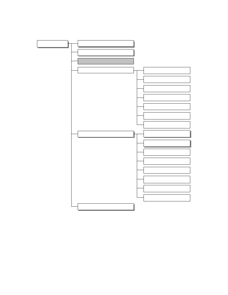
- 123 -
Fig. 48 Exif Audio File Configuration
RIFF Chunk
RIFF Chunk
"WAVE" (formType)
"WAVE" (formType)
fmt-ck (Format Chunk)
fmt-ck (Format Chunk)
fact-ck (Fact Chunk)
INFO List Chunk
"INFO” (listType)
INAM-ck (Title)
IGNR-ck (Genre)
ICRD-ck (Date)
ICMT-ck (Comment)
IART-ck (Creator)
ICOP-ck (Copyright)
exif List Chunk
exif List Chunk
"exif" (listType)
"exif" (listType)
ever-ck (Version)
ever-ck (Version)
erel-ck (Related Information)
etim-ck (Time)
ecor-ck (Make)
emdl-ck (Model)
emnt-ck (Maker Note)
eucm-ck (User Comment)
data (Data Chunk)
data (Data Chunk)
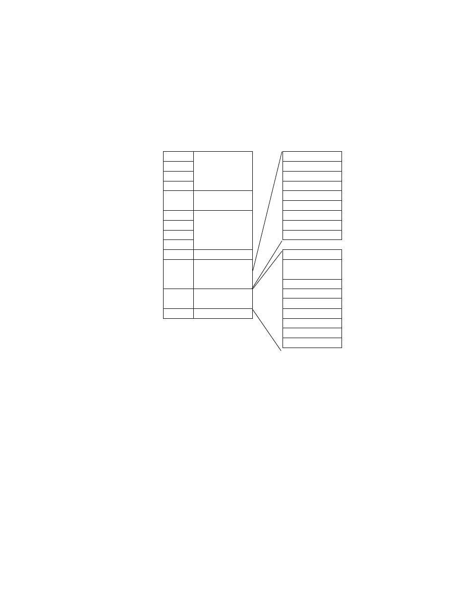
- 124 -
The means of recording the data of each element is given in the section for that element.
Fig. 49 shows the most common Exif audio file data structure. Exif audio file data is recorded in accord with the
structure shown in Fig. 49. Each sub-chunk is recorded in accord with its stipulations. Optional chunks may be
omitted.
Address Offset
Code
Meaning
Meaning
( Hex)
( Hex)
+00
52
"LIST"
+01
49
ckSize(4 Bytes )
+02
46
"INFO"
+03
46
"RIFF"
(ckID)
INAM-ck
IGNR -ck
+04
ckSize
(4 Bytes)
ICRD-ck
57
ICMT -ck
41
IART-ck
56
ICOP-ck
08
+09
+0A
+0B
45
"WAVE"
( formType)
+0C
fmt -ck
"LIST"
:
fact- ck
ckSize(4 Bytes )
"exif"
:
INFO List Chunk
ever - ck
erel- ck
:
exif List Chunk
etim- ck
:
data- ck
ecor - ck
emdl-ck
emnt-ck
eucm-ck
Fig. 49 Data Structure of a Typical Exif Audio File

- 125 -
Appendix A Image File Description Examples
A.1 Uncompressed RGB File
Table 33 Uncompressed RGB File Description Sample Contents
Primary I m a g e
Pixels
640 (W) x 480 (H )
Image Title
Exif_TIFF_RGB
Image Input Equipment Manufacturer
DSCompany
Image Input Equipment Model Name
Example
Orientation
Normal
Strips
9 6
Lines per Strip
5
Bytes per Strip
9600
Image Resolution
7 2 dpi (Width ), 72 dpi (Length)
Image Data Arrangement
Chunky
File Change Date and Time
1997:09:01 12:00:00.000
Copyright
Copyright, ABCDE,1997
Exif-specific Information
Version
Ver. 2.0
Date and Time of Original Image Creation
1997:09:01 12:00:00.000
Date and Time of File Creation
1997:09:01 12:00:00.000
Thumbnail
Pixels
8 0 (W) x 60 (H)
Orientation
Normal
Strips
1
Lines per Strip
6 0
Bytes per Strip
14400
Image Resolution
7 2 dpi (Width ), 72 dpi (Length)

- 126 -
Table 34 Uncompressed RGB File Description Sample
Offset
(Hex)
Name
Data
(Hex or "ASCII")
0000
Byte Order
4D4D ("MM" )
0002
4 2
002A
Header
0004
0th IFD Offset
00000008
Offset
(Hex)
Name
Interoperability Number
(Hex)
0008
Number of Interoperability
0014
Offset
(Hex)
Name
Tag ID
(Hex)
Type
(Hex)
Count
(Hex)
ValueOffset
(Hex or "ASCII")
000A
ImageWidth
0100
0004
00000001
00000280
0016
ImageLength
0101
0004
00000001
000001E0
0022
BitsPerSample
0102
0003
00000003
000000FE
002E
Compression
0103
0003
00000001
00010000
003A
PhotometricInterpretation
0106
0003
00000001
00020000
0046
ImageDescription
010E
0002
0000000E
00000104
0052
Make
0 1 0 F
0002
00000009
00000112
005E
Model
0110
0002
00000008
0000011C
006A
StripOffsets
0111
0004
00000060
00000124
0076
Orientation
0112
0003
00000001
00010000
0082
SamplesPerPixel
0
0003
00000001
00030000
008E
RowsPerStrip
0116
0004
00000001
00000005
009A
StripByteCounts
0117
0004
00000060
000002A4
00A6
XResolution
011A
0005
00000001
00000424
00B2
YResolution
011B
0005
00000001
0000042C
00BE
PlanarConfiguration
011C
0003
00000001
00010000
00CA
ResolutionUnit
0128
0003
00000001
00020000
00D6
DateTime
0132
0002
00000014
00000434
00E2
Copyright
8298
0002
00000015
00000484
00EE
Exif IFD Pointer
8769
0004
00000001
0000045E
Offset
(Hex)
Name
Offset
(Hex)
0th IFD
00FA
Next IFD Offset
000004EC
Offset
(Hex)
Name
Data
(Hex or "ASCII")
00FE
BitPerSample Value
000800080008
0104
ImageDescription Value
"Exif_TIFF_RGB"00
0112
Make Value
"DSCompany"00
011C
Model Value
"Example"00
0124
StripOffsets Value
offset0,offset1,offset2.....offset95
02A4
StripByteCounts Value
count0, count1, count2....count95
0424
XResolution Value
00000048000 00001
042C
YResolution Value
0000004800000001
0434
DateTime Value
"1997:09:01 12:00:00"00
Value
longer than
4byte of 0th
IFD
0448
Copyright Value (Last Byte is Padded)
"Copyright,ABCDE,1997"0000
Offset
(Hex)
Name
Interoperability Number
(Hex)
045E
Exif IFD Number
0008
Offset
(Hex)
Name
Tag ID
(Hex)
Type
(Hex)
Count
(Hex)
ValueOffset
(Hex or "ASCII")
0460
ExifVersion
9000
0007
00000004
"0200"
Exif IFD
046C
DateTimeOriginal
9003
0002
00000014
000004C4

- 127 -
0478
DateTimeDigitized
9004
0002
00000014
000004D8
0484
SubSecTime
9290
0 00 2
00000004
"000"00
0490
SubSecTimeOriginal
9291
0002
00000004
"000"00
049C
SubSecTimeDigitized
9292
0002
00000004
"000"00
04A8
FlashPixVersion
A000
0007
00000004
"0100"
04B4
Colorspace
A001
0003
00000001
0001
Offset
(Hex)
Name
Offset
(Hex)
04C0
Next IFD Offset
00000000
Offset
(Hex)
Name
Data
(Hex or "ASCII")
04C4
SubSecTimeOriginal Value
"1997:09:01 12:00:00"00
Value
longer than
4byte of Exif
IFD
04D8
SubSecTimeDigitized Value
"1997:09:01 12:00:00"00
Offset
(Hex)
Name
Interoperability Number
(Hex)
04EC
Number Of Interoperability
000D
Offset
(Hex)
Name
Tag ID
(Hex)
Type
(Hex)
Count
(Hex)
ValueOffset
(Hex)
04EE
ImageWidth
0100
0004
00000001
00000050
04FA
ImageLength
0101
0004
00000001
0000003C
0506
BitsPerSample
0102
0003
00000003
0000058E
0512
Compression
0103
0003
00000001
00010000
051E
PhotometricInterpretation
0106
0003
00000001
00020000
052A
StripOffsets
0111
0004
00000001
000005A4
0536
SamplesPerPixel
011
0003
00000001
00030000
0542
RowsPerStrip
0116
0004
000 00001
0000003C
054E
StripByteCounts
0117
0004
00000001
00003840
055A
XResolution
011A
0005
00000001
00000594
0566
YResolution
011B
0005
00000001
0000059C
0572
PlanarConfiguration
011C
0003
00000001
00010000
057E
ResolutionUnit
0128
0003
00000001
00020000
Offset
(Hex)
Name
Offset
(Hex)
1st IFD
058A
Next IFD Offset
00000000
Offset
(Hex)
Name
Data
(Hex or "ASCII")
058E
BitPerSample Value
000800080008
0594
XResolution Value
0000004800000001
059C
YResolution Value
0000004800000001
Value
longer than
4byte of 1st
IFD
05A4
Thumbnail Image Data Strip
:
Offset
(Hex)
Name
Data
(Hex or "ASCII")
3DE4
Primary Image Data Strip0
:
6364
Primary Image Data Strip1
:
:
:
:
:
:
:
Primary Image
0E2864
Primary Image Data Strip95
:

- 128 -
A.2 Uncompressed YCbCr File
Table 35 Uncompressed YCbCr File Description Sample Contents
Primary I m a g e
Pixels
640 (W) x 480 (H )
Image Title
Exif_TIFF_YCC
Image Input Equipment Manufacturer
DSCompany
Image Input Equipment Model Name
Example
Orientation
Normal
Strips
6 9
Lines per Strip
7
Bytes per Strip
8960
Image Resolution
7 2 dpi (Width ), 72 dpi (Length)
Image Data Arrangement
Chunky
File Change Date and Time
1997:09:01 12:00:00
Pixel Composition
Subsampling = 4:2:2
Chrominance Subsampling point matches
luminance point
Copyright
Copyright, ABCDE,1997
Exif-specific Information
Version
Ver. 2.0
Date and Time of Original Image Creation
1997:09:01 12:00:00
Date and Time of File Creation
1997:09:01 12:00:00
Shutter Speed
59/10 (equivalent to 1/60 sec.)
Aperture
50/10 (equivalent to F:5.6)
Brightness
80/10
Exposure Bias
0/0
Maximum Lens Aperture
200/10
Subject Distance
20/10
Metering Mode
MultiSpot
Light Source
Daylight
Flash ON/OFF
ON
GPS Information
Version
Ver. 2.0
Measurement Position
North Latitude 3 5 deg. 4 8 min. 8 sec., East
Longitude 1 3 9 deg. 3 4 min. 5 5 sec.
Altitude
3 0.48 meters above sea level
GPS Time
0:0 0:0 0
GPS Receiver Movement
Moving at 1km/h at 0 deg. true direction
Image Direct ion
0 deg. true direction
Geodetic Data Used for Measurement
TOKYO
Thumbnail
Pixels
8 0 (W) x 60 (H)
Orientation
Normal
Strips
1
Lines per Strip
6 0
Bytes per Strip
9600
Image Resolution
7 2 dpi (Width ), 72 dpi (Length)

- 129 -
Table 36 Uncompressed YCbCr File Description Sample
Offset
(Hex)
Name
Data
(Hex or "ASCII")
0000
Byte Order
4D4D ("II")
0002
4 2
2A00
Header
0004
0th IFD Offset
08000000
Offset
(Hex)
Name
Interoperability Number
(Hex)
0008
Number of Interoperability
1700
Offset
(Hex)
Name
Tag ID
(Hex)
Type
(Hex)
Count
(Hex)
ValueOffset
(Hex or "ASCII")
000A
ImageWidth
0001
0400
01000000
80020000
0016
ImageLength
0101
0400
01000000
E0010000
0022
BitsPerSample
0201
0300
03000000
22010000
002E
Compression
0301
0300
01000000
01000000
003A
PhotometricInterpretation
0601
0300
01000000
06000000
0046
ImageDescription
0E01
0200
0E000000
28010000
0052
Make
0F01
0200
09000000
36010000
005E
Model
1001
0200
08000000
40010000
006A
StripOffsets
1101
0400
45000000
48010000
0076
Orientation
1201
0300
01000000
01000000
0082
SamplesPerPixel
1501
0300
01000000
03000000
008E
RowsPerStrip
1601
0400
01000000
07000000
009A
StripByteCounts
1701
0400
45000000
5C020000
00A6
XResolution
1A01
0500
01000000
70030000
00B2
YResolution
1B01
0500
01000000
78030000
00BE
PlanarConfiguration
1C01
0300
01000000
01000000
00CA
ResolutionUnit
2801
0300
01000000
02000000
00D6
DateTime
3201
0200
14000000
80030000
00E2
YCbCrSubSampling
1202
0300
02000000
0200010 0
00EE
YCbCrPositioning
1302
0300
01000000
02000000
00FA
Copyright
9882
0200
15000000
94030000
0106
Exif IFD Pointer
6987
0400
01000000
AA030000
0112
GPS IFD Offset
2588
0400
01000000
10050000
Offset
(Hex)
Name
Offset
(Hex)
0th IFD
011E
Next IFD Offset
7E060000
Offset
(Hex)
Name
Data
(Hex or "ASCII")
0122
BitPerSample Value
080008000800
0128
ImageDescription Value
"Exif_TIFF_YCC"00
0136
Make Value
"DSCompany"00
0140
Model Value
"Example"00
0148
StripOffsets Value
(offset0,offset1,offset2.....offset95)
025C
StripByteCounts Value
(count0, count1, count2....count95)
0370
XResolution Value
4800000001000000
037C
YResolution Value
4800000001000000
0380
DateTime Value
"1997:09:01 12:00:00"00
Value
longer than
4byte of
0th IFD
0394
Copyright Value
(Last Byte is Padded)
"Copyright,ABCDE,1997"0000
Offset
(Hex)
Name
Interoperability Number
(Hex)
Exif IFD
03AA
Exif IFD Number
1400

- 130 -
Offset
(Hex)
Name
Tag ID
(Hex)
Type
(Hex)
Count
(Hex)
ValueOffset
(Hex or "ASCII")
03AC
ExposureTime
9A82
0500
01000000
A0040000
03B8
FNumber
9D82
0500
01000000
A8040000
03C4
ExifVersion
0090
0700
04000000
"0200"
03D0
DateTimeOriginal
0390
0200
14000000
B0040000
03DC
DateTimeDigitized
0490
0200
14000000
C4040000
03E8
ShutterSpeedValue
0192
0A00
01000 000
D8040000
03F4
ApertureValue
0292
0500
01000000
E0040000
0400
BrightnessValue
0392
0A00
01000000
E8040000
040C
ExposureBiasValue
0492
0A00
01000000
F0040000
0418
MaxApertureRatioValue
0592
0500
01000000
F8040000
0424
SubjectDistance
0692
0500
01000000
00050000
0430
MeteringMode
0792
0300
01000000
01000000
043C
LightSource
0892
0300
01000000
01000000
0448
Flash
0992
0300
01000000
0 1000000
0454
FocalLength
0A92
0500
01000000
08050000
0460
SubSecTime
9092
0200
04000000
"000"00
046C
SubSecTimeOriginal
9192
0200
04000000
"000"00
0478
SubSecTimeDigitized
9292
0200
04000000
"000"00
0484
FlashPixVersion
A000
0700
04000000
"0100"
0490
ColorSpace
A001
0300
01000000
01000000
Offset
(Hex)
Name
Offset
(Hex)
049C
Next IFD Offset
00000000
Offset
(Hex)
Name
Data
(Hex or "ASCII")
04A0
ExposureTime Value
010000003C000000
04A8
FNumber Value
0400000001000000
04B0
DateTimeOriginal Value
"1997:09:01 12:00:00"00
04C4
DateTimeDigitized Value
"1997:0 9:01 12:00:00"00
04D8
ShutterSpeed Value
0600000001000000
04E0
ApertureValue Value
0400000001000000
04E8
BrightnessValue Value
0000000001000000
04F0
ExposureBiasValue Value
0000000001000000
04F8
MaxApertureRatio Value
0100000001000000
0500
SubjectDistance Value
0F0000000A000000
Value
longer than
4 Bytes of
Exif IFD
0508
FocalLength Value
3200000001000000
Offset
(Hex)
Name
Interoperability Number
(Hex)
0510
GPS IFD Number
0013
Offset
(Hex)
Name
Tag ID
(Hex)
Type
(Hex)
Count
(Hex)
ValueOffset
(Hex or "ASCII")
051 2
GPSVersionIF
0000
0100
04000000
02000000
051E
GPSLatitudeRef
0100
0200
02000000
"N"000000
052A
GPSLatitude
0200
0500
03000000
FA050000
0536
GPSLongitudeRef
0300
0200
02000000
"E"000000
0542
GPSLongitude
0400
0500
03000000
12060000
054E
GPSAltitudeRef
0500
0100
01000000
00000000
055A
GPSAltitude
0600
0500
01000000
2A060000
0566
GPSTimeStamp
0700
0500
03000000
32060000
0572
GPSSatellites
0800
0200
0D000000
4A060000
057E
GPSStatus
0900
0200
02000000
"A"000000
058A
GPSMeasureMode
0A00
0200
02000000
"2"000000
GPS IFD
0596
GPSDOP
0B00
0500
01000000
58060000

- 131 -
05A2
GPSSpeedRef
0C00
0200
02000000
"K"000000
05AE
GPSSpeed
0D00
0500
01000000
60060000
05BA
GPSTrackRef
0E00
0200
02000000
"T"000000
05C6
GPSTrack
0F00
0500
01000000
68060000
05D2
GPSImgDirectionRef
1000
0200
02000000
"T"000000
05DE
GPSImgDirection
1100
0500
01000000
70060000
05EA
GPSMapDatum
1200
0200
06000000
78060000
Offset
(Hex)
Name
Offset
(Hex)
05F6
Next IFD Offset
00000000
Offset
(Hex)
Name
Data
(Hex or "ASCII")
05FA
GPSLatitude Value
230000000100000030000000010000000800000001000000
0612
GPSLongitude Value
8B0000000100000022000000010000003700000001000000
062A
GPSAltitude Value
E80B000064000000
0632
GPSTimeStamp Value
0000000 00100000000000000010000000000000001000000
064A
GPSSatellites Value (Last Byte is
padded)
"2,7,14,15,16"0000
0658
GPSDOP Value
0100000001000000
0660
GPSSpeed Value
0000000001000000
0668
GPSTrack Value
0000000001000000
0670
GPSImgDirection Value
0 000000001000000
Value
longer than
4 Bytes of
GPS IFD
0678
GPSMapDatum Value
"TOKYO"00
Offset
(Hex)
Name
Interoperability Number
(Hex)
067E
Number Of Interoperability
0F00
Offset
(Hex)
Name
Tag ID
(Hex)
Type
(Hex)
Count
(Hex)
ValueOffset
(Hex or "ASCII")
0680
ImageWidth
0001
0 40 0
01000000
50000000
068C
ImageLength
0101
0400
01000000
3C000000
0698
BitsPerSample
0201
0300
03000000
38070000
06A4
Compression
0301
0300
01000000
01000000
06B0
PhotometricInterpretation
0601
0300
01000000
06000000
06BC
StripOffsets
1101
0400
01000000
4E070000
06C8
SamplesPerPixel
1501
0300
01000000
03000000
06D4
RowsPerStrip
1601
0400
01000000
3C000000
06E0
StripByteCounts
1701
0400
01000000
80250000
06EC
XResolution
1A01
0500
01000000
3E070000
06F8
YResolution
1B01
0500
01000000
46070000
0704
PlanarConfiguration
1C01
0300
01000000
01000000
0710
ResolutionUnit
2801
0300
01000000
02000000
071C
YCbCrSubSampling
1202
0300
02000000
02000100
0728
YCbCrPositioning
1302
0300
01000000
02000000
Offset
(Hex)
Name
Offset
(Hex)
1st IFD
0734
Ne xt IFD Offset
00000000
Offset
(Hex)
Name
Data
(Hex or "ASCII")
0738
BitPerSample Value
080008000800
073E
XResolution Value
4800000001000000
0746
YResolution Value
4800000001000000
Value
longer than
4byte of
1st IFD
074E
(Thumbnail Image Data St rip)
Offset
(Hex)
Name
Data
(Hex or "ASCII")
Primary Image
Data
2CCE
Image Data Strip0
:

- 132 -
4FCE
Image Data Strip1
:
:
:
:
:
:
:
0978CE
Image Data Strip68
:

- 133 -
A.3 JPEG Compressed (4:2:2) File
Table 37 JPEG Compressed ( 4:2:2 ) File Description Sample Contents
Primary I m a g e
Recording Format
JPEG
Subsampling
YCC 4:2:2
Restart Markers
Inserted
Quantization Tables
3
Pixels
640 (W) x 480 (H )
Image Title
Exif_JPEG_422
Image Input Equipment Manufacturer
DS Company
Image Input Equipment Model Name
Example
Orientation
Normal
Image Resolution
7 2 dpi (Width ), 72 dpi (Length)
File Change Date and Time
1997:09:01 12:00:00
Copyright
Copyright, ABCDE,1997
Exif-specific Information
Version
Ver. 2.0
Date and Time of Original Image Creation
1997:09:01 12:00:00
Date and Time of File Creation
1997:09:01 12:00:00
Components
Y,Cb,Cr
Image Compression Mode
2bit/pel
Shutter Speed
59/10 (equivalent to 1/60 sec.)
Aperture
50/10 (equivalent to F:5.6)
Brightness
80/1 0
Exposure Bias
0/0
Maximum Lens Aperture
200/10
Subject Distance
20/10
Metering Mode
MultiSpot
Light Source
Daylight
Flash ON/OFF
ON
Thumbnails
Recording Format
JPEG
Subsampling
YCC 4:2:2
Pixels
8 0 (W) x 60 (H)
Image Resolution
7 2 d p i (Width), 72 dpi (Length)

- 134 -
Table 38 JPEG Compressed (4:2:2 ) File JPEG Stream Description Sample
Offset
(Hex)
Maker Segment
Name
Code
(Hex)
Comment
0000
SOI
SOI Marker
FFD8
Start of Image
0002
APP1 Marker
FFE1
0004
APP1 Length
291C
0006
Identifier
"Exif"00
000B
Pad
0 0
000C
APP1
APP1 Body
See Next Table
0E39
DQT Marker
FFDB
Define Quantization Table
0E3B
DQT Length
00C5
0E3D
Pq, Tq
0 0
0E3E
table elements
100B0C0E.....
64 Bytes of Data
0E7E
Pq,Tq
0 1
0 E7F
table elements
0F101016....
64 Bytes of Data
0EBF
Pq,Tq
0 2
0EC0
DQT
table elements
0F101016....
64 Bytes of Data
0F00
DHT Marker
FFC4
0F02
DHT Length
01A2
0F04
Th
0 0
Table 0 for DC
0F05
L i
00010501....
0F15
Vij
00010203....
0F21
Th
1 0
Table 0 for AC
0F22
L i
00020103....
0F32
Vij
01020300....
0FD4
Th
0 1
Table 1 for DC
0FD5
L i
00030101....
0FE5
Vij
00010203....
0FF1
Th
11
Table 1 for AC
0FF2
L i
00020102....
1002
D H T
Vij
00010203....
10A4
DRI Marker
FFDD
10A6
DRI Length
0004
10A8
D R I
Ri
0004
10AA
SOF0 Marker
FFC0
10AC
SOF0 Leng th
0011
10AE
P
0 8
10AF
Y
01E0
10B1
X
0280
10B3
Nf
0 3
10B4
C1
0 1
10B5
H1,V1
2 1
10B6
Tq1
0 0
10B7
C2
0 2
10B8
H2,V2
11
10B9
Tq2
0 1
10BA
C3
0 3
10BB
H3,V3
11
10BC
SOF0
Tq3
0 2
10BD
SOS Marker
FFDA
10BF
SOS Length
000C
10C1
Ns
0 3
10C2
SOS
C s 1
0 1
- 135 -
10C3
Td1,Ta1
0 0
10C4
C s 2
0 2
10C5
Td2,Ta2
11
10C6
C s 3
0 3
10C7
Td3,Ta3
11
10C8
Ss
0 0
10C9
Se
3 F
10CA
Ah,Al
0 0
10CB
Image Data
F36A....
Compressed Data
111C4
EOI
FFD9

- 136 -
Table 39 JPEG Compressed ( 4:2:2 ) File APP1 Description Sample
Offset
(Hex)
Name
Data
(Hex or "ASCII")
0000
Byte Order
4D4D ("II")
0002
4 2
2A00
Header
0004
0th IFD Offset
08000000
Offset
(Hex)
Name
Interoperability Number
(Hex)
0008
Number of Interoperability
0B00
Offset
(Hex)
Name
Tag ID
(Hex)
Type
(Hex)
Count
(Hex)
ValueOffset
(Hex or "ASCII")
000A
ImageDescription
0E01
0200
0E000000
92000000
0016
Make
0F01
0200
09000000
A0000000
0022
Model
1001
0200
08000000
AA000000
002E
Orientation
1201
0300
01000000
01000000
003A
XResolution
1A01
0500
01000000
B2000000
0046
YResolution
1B01
0500
01000000
BA000000
0052
ResolutionUnit
2801
0300
01000000
02000000
005E
DateTime
3201
0200
14000000
C2000000
006A
YCbCrPositioning
1302
0300
01000000
02000000
0076
CopyRight
9882
0200
15000000
D6000000
0082
Exif IFD Pointer
6987
0400
01000000
EC000000
Offset
(Hex)
Name
Offset
(Hex)
0th IFD
008E
Next IFD Offset
C402
Offset
(Hex)
Name
Data
(Hex or "ASCII")
0092
ImageDescription Value
"Exif_JPEG_422"00
00A0
Make Value
"DSCompany"00
00AA
Model Value
"Example"00
00B2
XResolution Value
4800000001000000
00BA
YResolution Val u e
4800000001000000
00C2
DateTime Value
"1997:09:01 12:00:00"00
Value
longer than
4byte of 0th IFD
00D6
Copyright Value (Last Byte is Padded)
"Copyright,ABCDE,1997"0000
Offset
(Hex)
Name
Interoperability Number
(Hex)
00EC
Exif IFD Number
1900
Offset
(Hex)
Name
Tag ID
(Hex)
Type
(Hex)
Count
(Hex)
ValueOffset
(Hex or "ASCII")
00EE
ExposureTime
9A82
0500
01000000
1E020000
00FA
FNumber
9D82
0500
01000000
26020000
0106
ExifVersion
0090
0700
04000000
"0200"
0112
DateTimeOriginal
0390
0200
14000000
2E020000
011E
DateTimeDigitized
0490
0200
14000000
42020000
012A
ComponentsConfiguration
0191
0700
04000000
01020000
0136
CompressedBitsPerPixel
0292
0500
01000000
56020000
0142
ShutterSpeedValue
0192
0A00
01000000
5E020000
014E
ApertureValue
0292
0500
01000000
66020000
015A
BrightnessValue
0392
0A00
01000000
6E020000
0166
ExposureBiasValue
0492
0A00
01000000
76020000
0172
MaxApertureRatioValue
0592
0500
01000000
7E020000
017E
SubjectDistance
0692
0500
01000000
86020000
Exif IFD
018A
MeteringMode
0792
0300
01000000
01000000

- 137 -
0196
LightSource
0892
0300
01000000
01000000
01A2
Flash
0992
0300
01000000
00000000
01AE
FocalLength
0A92
0500
01000000
8E020000
01BA
UserComments
8692
0700
2E000000
96020000
01C6
SubSecTime
9092
0200
04000000
"000"00
01D2
SubSecTimeOrigin a l
9192
0200
04000000
"000"00
01DE
SubSecTimeDigitized
9292
0200
04000000
"000"00
01EA
FlashPixVersion
A000
0700
04000000
"0100"
01F6
Colorspace
A001
0300
01000000
01000000
0202
Pixel X Dimension
A002
0400
01000000
80020000
020E
Pixel Y Dimension
A003
0400
01000000
E0010000
Offset
(Hex)
Name
Offset
(Hex)
021A
Next IFD Offset
00000000
Offset
(Hex)
Name
Data
(Hex or "ASCII")
021E
ExposureTime Value
010000003C000000
0226
FNumber Value
0400000001000000
022E
DateTimeOriginal Value
"1997:09:01 12:00:00"00
0242
DateTimeDigitized Value
"1997:09:01 12:00:00"00
0256
CompressedBitsPerPixel Value
0200000001000000
025E
ShutterSpeedValue Value
0600000001000000
0266
ApertureValue Value
0400000001000000
026E
BrightnessValue Value
0000000001000000
0276
ExposureBiasValue Value
0000000001000000
027E
MaxApertureRatioValue Value
0100000001000000
0286
SubjectDistance Value
0F0000000A000000
028E
FocalLength Value
3200000001000000
Value
longer than
4 Bytes of
Exif IFD
0296
UserComment Value (46 Bytes)
4A49530000000000....
Offset
(Hex)
Name
Interoperability Number
(Hex)
02C4
Number Of Interoperability
0700
Offset
(Hex)
Name
Tag ID
(Hex)
Type
(Hex)
Count
(Hex)
ValueOffset
(Hex or "ASCII")
02C6
Compression
0301
0300
01000000
010 00000
02D2
XResolution
1A01
0500
01000000
1E030000
02DE
YResolution
1B01
0500
01000000
26030000
02EA
ResolutionUnit
2801
0300
01000000
02000000
02F6
JPEGInterchangeFormat
0102
0400
01000000
2D0E0000
0302
JPEGInterchangeFormatLength
0202
0400
01000000
FF0A0000
030E
YCbCrPositioning
1302
0300
01000000
02000000
Offset
(Hex)
Name
Offset
(Hex)
1st IFD
031A
Next IFD Offset
00000000
Offset
(Hex)
Data
(Hex or "ASCII")
Name
031E
4800000001000000
XResolution Value
Value
longer than
4byte of 1st IFD
0326
4800000001000000
YResolution Value
Offset
(Hex)
Name
Data
Thumbnail
Image Data
032E
Thumbnail Data
(JPEG Stream)

- 138 -
A.4 JPEG Compressed (4:2:0) File
Table 40 JPEG Compressed (4:2:0 ) File Description Sample Contents
Primary Image
Recording Format
JPEG
Subsampling
YCC 4:2:0
Restart Markers
Inserted
Quantization Tables
2
Pixels
620 (W) x 475 (H )
Image Title
620x475
SOF Recorded Pixels
640x475
D C T Data
640x480
Image Title
Exif_JPEG_420
Image Input Equipment Manufacturer
DSCompany
Image Input Equipment Model Name
Example
Orientation
Normal
Image Resolution
7 2 dpi (Width ), 72 dpi (Length)
File Change Date and Time
1997:09:01 12:00:00
Copyright
Copyright, ABCDE,1997
Exif-specific Information
Version
Ver. 2.0
Date and Time of Original Image Creation
1997:09:01 12:00:00
Date and Time of File Creation
1997:09:01 12:00:00
Components
Y,Cb,Cr
Image Compression Mode
2bit/pel
Shutter Speed
59/10 (equivalent to 1/60 sec.)
Aperture
50/10 (equivalent to F:5.6)
Brightness
80/10
Exposure Bias
0/0
Maximum Lens Aperture
200/10
Subject Distance
20/10
Metering Mode
MultiSpot
Light Source
Daylight
Flash ON/OFF
ON
Thumbnails
Recording Format
TIFF
Subsampling
YCC 4:2:0
Pixels
80x60
Image Res olution
7 2 dpi (Width ), 72 dpi (Length)

- 139 -
Table 41 JPEG Compressed ( 4:2:0) File JPEG Stream Description Sample
Offset
(Hex)
Maker Segment
Name
Code
(Hex)
Comment
0000
SOI
SOI Marker
FFD8
Start of Image
0002
APP1 Marker
FFE1
0004
APP1 Length
1FBC
0006
Identifier
"Exif"00
000B
Pad
0 0
000C
APP1
APP1 Body
See Next Table
1FC0
DQT Marker
FFDB
Define Quantization Table
1FC2
DQT Length
0084
1FC4
Pq, Tq
0 0
1FC5
table elements
08060607....
64 Bytes of Data
2005
Pq,Tq
0 1
2006
DQT
table elements
0909090C....
64 Bytes of Data
2046
DHT Marker
FFC4
2048
DHT Length
01A2
204A
Th
0 0
Table 0 for DC
204B
L i
00010501....
205B
Vij
00010203....
2067
Th
1 0
Table 0 for AC
2068
L i
00020103....
2078
Vij
010 20300....
211A
Th
0 1
Table 1 for DC
211B
L i
00030101....
212B
Vij
00010203....
2137
Th
11
Table 1 for AC
2138
L i
00020102....
2148
D H T
Vij
00010203....
21EA
DR Marker
FFDD
21EC
DRI Length
0004
21EE
D R I
Ri
0004
21F0
SOF0 Marker
FFC0
21F2
SOF0 Lentth
0011
21F4
P
0 8
21F5
Y
01DB
21F7
X
0280
21F9
Nf
0 3
21FA
C1
0 1
21FB
H1,V1
2 2
21FC
Tq1
0 0
21FD
C2
0 2
21FE
H2,V2
11
21FF
Tq2
0 1
2200
C3
0 3
2201
H3,V3
11
2202
SOF0
Tq3
0 1
2203
SOS Marker
FFDA
2205
SOS Length
000C
2207
Ns
0 3
2208
C s 1
0 1
2209
Td1,Ta1
0 0
220A
SOS
C s 2
0 2
- 140 -
220B
Td2,Ta2
11
220C
C s 3
0 3
220D
Td3,Ta3
11
220E
Ss
0 0
2 2 0 F
Se
3 F
2210
Ah,Al
0 0
2211
Image Data
F9FE....
Compressed Data
13BA4
EOI
FFD9

- 141 -
Table 42 JPEG Compressed ( 4:2:0 ) File APP1 Description Sample
Offset
(Hex)
Name
Data
(Hex or "ASCII")
0000
Byte Order
4D4D ("II")
0002
4 2
2A00
Header
0004
0th IFD Offset
08000000
Offset
(Hex)
Name
Interoperability Number
(Hex)
0008
Number of Interoperability
0B00
Offset
(Hex)
Name
Tag ID
(Hex)
Type
(Hex)
Count
(Hex)
ValueOffset
(Hex or "ASCII")
000A
ImageDescription
0E01
0200
0E000000
92000000
0016
Make
0F01
0200
09000000
A0000000
0022
Model
1001
0200
0800000 0
AA000000
002E
Orientation
1201
0300
01000000
01000000
003A
XResolution
1A01
0500
01000000
B2000000
0046
YResolution
1B01
0500
01000000
BA000000
0052
ResolutionUnit
2801
0300
01000000
02000000
005E
DateTime
3201
0200
14000000
C2000000
006A
YCbCrPositioning
1302
0300
01000000
02000000
0076
Copyright
9882
0200
15000000
D6000000
0082
Exif IFD Pointer
6987
0400
01000000
EC000000
Offset
(Hex)
Name
Offset
(Hex)
0th IFD
008E
Next IFD Offset
C402
Offset
(Hex)
Name
Data
(Hex or "ASCII")
0092
ImageDescription Value
"Exif_JPEG_420"00
00A0
Make Value
"DSCompany"00
00AA
Model Value
"Example"00
00B2
XResolution Value
4800000001000000
00BA
YResolution Value
4800000001000000
00C2
DateTime Value
"1997:09:01 12:00:00"00
Value
longer than
4byte of 0th
IFD
00D6
Copyright Value (Last Byte is Padded)
"Copyright,ABCDE,1997"0000
Offset
(Hex)
Name
Interoperability Number
(Hex)
00EC
Exif IFD Number
1900
Offset
(Hex)
Name
Tag ID
(Hex)
Type
(Hex)
Count
(Hex)
ValueOffset
(Hex or "AS CII")
00EE
ExposureTime
9A82
0500
01000000
1E020000
00FA
FNumber
9D82
0500
01000000
26020000
0106
ExifVersion
0090
0700
04000000
"0200"
0112
DateTimeOriginal
0390
0200
14000000
2E020000
011E
DateTimeDigitized
0490
0200
14000000
42020000
012A
ComponentsConfiguration
0191
0700
04000000
01020300
0136
CompressedBitsPerPixel
0292
0500
01000000
56020000
0142
ShutterSpeedValue
0192
0A00
01000000
5E020000
014E
ApertureValue
0292
0500
01000000
66020000
015A
BrightnessValue
0392
0A00
01000000
6E020000
0166
ExposureBiasValue
0492
0A00
01000000
76020000
0172
MaxApertureRatioValue
0592
0500
01000000
7E020000
017E
SubjectDistance
0692
0500
01000000
86020000
Exif IFD
018A
MeteringMode
0792
0300
01000000
01000000

- 142 -
0196
LightSource
0892
0300
01000 000
01000000
01A2
Flash
0992
0300
01000000
00000000
01AE
FocalLength
0A92
0500
01000000
8E020000
01BA
UserComments
8692
0700
2E000000
96020000
01C6
SubSecTime
9092
0200
04000000
30303000
01D2
SubSecTimeOriginal
9192
0200
04000000
"000"00
01DE
SubSecTimeDigitized
9292
0200
04000000
"000"00
01EA
FlashPixVersion
A000
0700
04000000
"0100"
01F6
ColorSpace
A001
0300
01000000
01000000
0202
Pixel X Dimension
A002
0400
01000000
6C020000
020E
Pixel Y Dimension
A003
0400
01000000
DB010000
Offset
(Hex)
Name
Offset
(Hex)
021A
Next IFD Offset
00000000
Offset
(Hex)
Name
Data
(Hex or "ASCII")
021E
ExposureTime Value
010000003C000000
0226
FNumber Value
0400000001000000
022E
DateTimeOriginal Value
"1997:09:01 12:00:00"00
0242
DateTimeDigitized Value
"1997:09:01 12:00:00"00
0256
CompressedBitsPerPixel Value
0200000001000000
025E
ShutterSpeedValue Value
0600000001000000
0266
ApertureValue Value
0400000001000000
026E
BrightnessValue Value
0 000000001000000
0276
ExposureBiasValue Value
0000000001000000
027E
MaxApertureRatioValue Value
0100000001000000
0286
SubjectDistance Value
0F0000000A000000
028E
FocalLength Value
3200000001000000
Value
longer than
4 Bytes of
Exif IFD
0296
UserComment Value (46 Bytes)
4A49530000000000....
Offset
(Hex)
Name
Interoperability Number
(Hex)
02C4
Number Of Interoperability
0F00
Offset
(Hex)
Name
Tag ID
(Hex)
Type
(Hex)
Count
(Hex)
ValueOffset
(Hex or "ASCII")
02C6
ImageWidth
0001
0400
01000000
50000000
02D2
ImageLength
0101
0400
01000000
3C000000
02DE
BitsPerSample
0201
0300
03000000
7E030000
02EA
Compression
0301
0300
01000000
01000000
02F6
PhotometricInterpretation
0601
0300
01000000
06000000
0302
StripOffsets
1101
0400
01000000
94030000
030E
S a m p l e s PerPixel
1501
0300
01000000
03000000
031A
RowsPerStrip
1601
0400
01000000
3C000000
0326
StripByteCounts
1701
0400
01000000
201C0000
0332
XResolution
1A01
0500
01000000
84030000
033E
YResolution
1B01
0500
01000000
8C030000
034A
PlanarConfiguration
1C01
0300
01000000
01000000
0356
ResolutionUnit
2801
0300
01000000
02000000
0362
YCbCrSubSampling
1202
0300
02000000
02000200
036E
YCbCrPositioning
1302
0300
01000000
02000000
Offset
(Hex)
Name
Offset
(Hex)
1st IFD
037A
Next IFD Offset
00000000
Value
longer than
Offset
(Hex)
Name
Data
(Hex or "ASCII")

- 143 -
037E
BitsPerSample Value
080008000800
0384
XResolution Value
4800000001000000
4byte of 1st
IFD
038C
YResolution Value
4800000001000000
Offset
(Hex)
Name
Data
(Hex or "ASCII")
Thumbnail
Image Data
0394
Thumbnail Image Data Strip
:

- 144 -
Appendix B Audio File Description Examples
B.1 PCM Audio Data
Table 43 PCM Audio File Description Sample Contents
Audio Data
Format Type
PCM Format
Channels
monaural
Sampling Frequenc y
22.05 kHz
Bits per Sample
8 Bits/Sample
Total Samples
27768 Samples
Attribute Information
Audio Title
ExifPCMExampleZ
Audio Genre
None
Recording Date
1997-0 7-1 3
Recording Engineer
Taro Yamada
Copyright
Copyright Exif Corporation on 1997 .
Exif-specific Information
Exif Version
0200 (Version 2.0 )
Related Exif Image File
DSC00001.JPGZ
Recording Start Time
10:15:30.130Z
Recording Equipment Manufacturer
DSC CorporationZ
Recording Equipment Model
DSC1000Z
Manufacturer Note
None
User Comment
None

- 145 -
Table 44 PCM Audio File Description Example
Offset
(Hex)
Name
Comment
Data
(Hex or "ASCII")
RIFF-c k
0000
ckID
RIFF
52494646
0004
ckSize
766D0000
0008
formType
WAVE
57415645
fmt -c k
000C
ckID
fmt_
666D7420
0010
ckSize
10000000
0014
wFormatTag
PCM Format
0100
0016
nchannels
monaural
0100
0018
nSamplesPerSec
22.05 kHz
22560000
001C
nAvgBytesPerSec
22050 bytes /sec
22560000
0020
nBlockAlign
1 byte/block
0100
0022
wBitsPerSample
8 bits/sample
0800
INFO-LIST
0024
ckID
LIST
4C495354
0028
ckSize
6E000000
002C
listType
"INFO"
494E464F
INAM-c k
0030
ckID
INAM
494E414D
0034
ckSize
0F000000
0038
ckData
(audio title)
"ExifPCMExample"0000
ICRD-c k
0048
ckID
ICRD
49435244
004C
ckSize
0B000000
0050
ckData
(July 13, 1997)
"1997 -0 7-13"0000
IART-c k
005C
ckID
IART
49415254
0060
ckSize
0C000000
0064
ckData
(creator)
"Taro Yamada"00
ICOP-c k
0070
ckID
ICOP
49434F50
0074
ckSize
21000000
0078
ckData
(copyright)
"Copyright Exif Corporation on
1997."0000
exif-LIST
009A
ckID
LIST
4C495354
009E
ckSize
64000000
00A2
listType
exif
65786966
ever-c k
00A6
ckID
ever
65766572
00AA
ckSize
4000000
00AE
ckData
Ver. 2.0
200
e r e l-c k
00B2
ckID
erel
6572656C
00B6
ckSize
0D000000
00BA
ckData
(relation to Exif image file)
"DSC00001.JPG"0000
etim-c k
00C8
ckID
etim
6574696D
00CC
ckSize
0D000000
00D0
ckData
(1 0:1 5:30.130)
"10:15:30.130"0000
ecor-c k
00DE
ckID
ecor
65636F72
00E2
ckSize
10000000
00E6
ckSize
(equipment manufacturer)
"DSC Corporation"00
emdl -c k
00F6
ckID
emdl
656D646C
00FA
ckSize
8000000
00FE
ckData
(equipment model)
"DSC1000"00
data-c k
0106
ckID
data
64617461
010A
ckSize
706C0000
010E
ckData
PCM Audio Data
00000000000 .....................
(Total samples = 27768 )

- 146 -
B.2
µ
-Law Audio Data
Table 45
µ
-Law Audio File Description Sample Contents
Audio Data
Format Type
µ
-LAW PCM
Channels
monaural
Sampling Frequency
8.000 kHz
Bits per Sample
8 bits
Total Samples
111912
Attribute Information
Audio Title
µ
-LAW PCM ExampleZ
Audio Genre
GreetingZ
Recording Date
1997-0 7-1 7
Recording Engineer
Interoperability Multimedia AssociationZ
Copyright
Copyright ABCZ
Exif-specific In formation
Exif Version
0200 (Version 2.0 )
Related Exif Image File
DSC00001.JPGZ
Recording Start Time
10:20:30.130Z
Recording Equipment Manufacturer
ABCD CorporationZ
Recording Equipment Model
Camera XYZZ
Manufacturer Note
0000000000000000
U ser Comment
User Comment (ASCII)
- 147 -
Table 46
µ
-Law Audio File Description Sample
Offset
(Hex)
Name
Comment
Data
(Hex or " ASCII" )
RIFF-c k
0000
ckID
RIFF
52494646
0004
ckSize
AAB60100
0008
formType
WAVE
57415645
fmt -c k
000C
ckID
fmt_
666D7420
0010
ckSize
12000000
0014
wFormatTag
µ
-L aw Format
0700
0016
nchannels
monaural
0100
0018
nSamplesPerSec
8.00 kHz
401F0000
001C
nAvgBytesPerSec
8.00Kb yte s/sec
401F0000
0020
nBlockAlign
1 byte/block
0100
0022
wBitsPerSample
8 bits/sample
0800
0024
cbSize
0
0000
fact-c k
0026
ckID
fact
66616374
002A
ckSize
04000000
002E
dwSampleLength
28B50100
INFO-LIST
0032
ckID
LIST
4C495354
0036
ckSize
AC000000
003A
listType
INFO
494E464F
INAM-c k
003E
ckID
INAM
494E414D
0042
ckSize
12000000
0046
ckData
(audio title)
"uLAW PCM Example"00
IGNR-c k
0058
ckID
IGNR
49474E52
005C
ckSize
09000000
0060
ckData
(recording genre)
"Greeting"Z
ICRD-c k
006A
ckID
ICRD
49435244
006E
ckSize
0B000000
0072
ckData
(July 17, 1997)
"1997-0 7-17"00
ICMT-c k
007E
ckID
ICMT
49434D54
0082
ckSize
18000000
0086
ckData
(This File
µ
-LAW Sample)
"This File uLAW Sample"000000
IART-c k
009E
ckID
IART
49415254
00A2
ckSize
23000000
00A6
ckData
(creator)
"Interoperability Multimedia Association"00
ICOP-c k
00CA
ckID
ICOP
49434F50
00CE
ckSize
10000000
00D2
ckData
(creator)
"ABCD Corporation"00
exif-LIST
00E2
ckID
LIST
4C495354
00E6
ckSize
94000000
00EA
listType
exif
65786966
ever-c k
00EE
ckID
ever
4C495354
00F2
ckSize
94000000
00F6
ckData
Ver. 2.0
65786966
e r e l-c k
00FA
ckID
erel
4C495354
00FE
ckSize
94000000
0102
ckData
(relation to Exif image file)
"DSC00001.JPG"00
etim -c k
0110
ckID
etim
4C495354
0114
ckSize
94000000
0118
ckData
(1 0:20:30.130)
"10:20:30.130"00
ecor-c k
0126
ckID
ecor
4C495354
012A
ckSize
94000000

- 148 -
012E
ckSize
(equipment manufacturer)
"ABCD Corporation"00
emdl -c k
0140
ckID
emdl
656D646C
0144
ckSize
0A000000
0148
ckData
(equipment mod el)
"Camera XY"0000
emnt -c k
0152
ckID
emnt
656D6E74
0156
ckSize
08000000
015A
ckData
(manufacturer note)
0000000000000000
eucm-c k
0162
ckID
eucm
6575636D
0166
ckSize
14000000
016A
ckData
(user comment)
41534349490000005573657220436F6D
data -c k
017E
ckID
data
64617461
0182
ckSize
28B50100
0186
ckData
µ
-Law Audio Data
F2FE00007FFF0000E3................
(Total samples = 111912)

- 149 -
B.3 IMA-ADPCM Audio Data
Table 47 IMA- ADPCM Audio File Description Sample Contents
Audio Data
Format Type
IMA-ADPCM Format
Channels
stereo
Sampling Frequency
8.000 kHz
Bytes per Block
8110 bytes/sec
Bits per Sample
4 bits/sample
Total Data Bytes
35840 bytes
Attribute Information
Audio Title
IMA-ADPCM ExampleZ
Audio Genre
None
Recording Date
1997-0 8-11Z
C o m m e n t
None
Recording Engineer
Hanako YamadaZ
Copyright
Copyright XYZ on 1997.Z
Exif-specific Information
Exif Version
0200 (Version 2.0 )
Related Exif Image File
DSC00001.JPGZ
Recording Start Time
15:14:1 3.135Z
Recording Equipment Manufacturer
DSC Interoperability CorporationZ
Recording Equipment Model
DSC Camera-2 Z
Manufacturer Note
None
User Comment
None

- 150 -
Table 48 IMA- ADPCM Audio File Description Example
Offset
(Hex)
Name
Comment
Data
(Hex or " ASCII")
RIFF-c k
0000
ckID
RIFF
52494646
0004
ckSize
248D0000
0008
formType
WAVE
57415645
fmt-c k
000C
ckID
"fmt_"
666D7420
0010
ckSize
IMA-ADPCM Format
14000000
0014
wFormatTag
1100
0016
nchannels
stereo
0200
0018
nSamplesPerSec
8.0kHz
401F0000
001C
nAvgBytesPerSec
8110 bytes /sec
AE1F0000
0020
nBlockAlign
512 bytes /block
0002
0022
wBitsPerSample
4 bits/sample
0400
0024
cbSize
Additional bytes = 2
0200
0026
wSamplesPerBlock
505 bytes /block
F901
fact-c k
0028
ckID
fact
66616374
002C
ckSize
04000000
0030
dwSampleLength
35350 samples
1 68 A0000
INFO-LIST
0034
ckID
LIST
4C495354
0038
ckSize
68000000
003C
listType
INFO
494E464F
INAM-c k
0040
ckID
INAM
494E414D
0044
ckSize
12000000
0048
ckData
(audio title)
"IMA-ADPCM Example"00
IGNR-c k
0058
ckID
IGNR
49474E52
005C
ckSize
09000000
0060
ckData
(recording genre)
"Greeting"Z
ICRD-c k
005A
ckID
ICRD
49435244
005E
ckSize
0B000000
0062
ckData
(August 11, 1997)
"1997 -0 8-11"0000
IART-c k
006E
ckID
IART
49415254
0072
ckSize
0E000000
0076
ckData
(creator)
"Hanako Yamada"00
ICOP-c k
0084
ckID
ICOP
49434F50
0088
ckSize
17000000
008C
ckData
(copyright)
"Copyright XYZ on 1997."0000
exif-LIST
00E2
ckID
LIST
4C49535 4
00E6
ckSize
94000000
00EA
listType
exif
65786966
ever-c k
00A4
ckID
LIST
4C495354
00A8
ckSize
78000000
00AC
listType
exif
65786966
e r e l-c k
00BC
ckID
erel
6572656C
00C0
ckSize
0D000000
00C4
ckData
(relation to Exif image file)
"DSC00001.JPG"0000
etim-c k
00D2
ckID
etim
6574696D
00D6
ckSize
0D000000
00DA
ckData
(1 5:1 4:13.135)
"15:14:13.135"0000
ecor-c k
00E8
ckID
ecor
65636F72
00EC
ckSize
1E000000
00F0
ckSize
(equipment manufacturer)
"DSC Interoperability Corporation"0 0
emdl -c k
010E
ckID
emdl
656D646C

- 151 -
0112
ckSize
0D000000
0116
ckData
(equipment model)
"DSC Camera -2"0000
data-c k
0124
ckID
data
64617461
0128
ckSize
008C0000
012C
ckData
..................................
(Total bytes = 35840 )
- 152 -
Appendix C APEX Units
The camera information in this standard conforms to the APEX (Additive System of Photographic Exposure ) unit
system. APEX is a convenient unit for expressing exposure (Ev). The relation of APEX to other units is essentially
as follows.
•
ApertureValue (Av) = 2 log
2
(F number)
•
ShutterSpeedValue (Tv) = - log
2
(exposure time)
•
BrightnessValue (Bv) = log
2
( B/NK ) Note that: B:cd/cm
2
, N,K: constant
Film sensitivity (not used in this standard) is expressed as follows.
•
Film sensitivity (Sv) = log
2
( ASA / 3.125 )
Using these values, exposure (Ev) is calculated as follows.
•
Ev = Av + Tv = Bv + Sv
The table below gives examples of values actually used as camera information.
Table 49 Typical APEX Values
ApertureValue
F-Number
Shutt erSpeed
Value
ExposureTime
BrightnessValue
foot lambert
(APEX)
(APEX)
(second)
(APEX)
0
1
-5
3 0
-2
1/4
1
1.4
-4
1 5
-1
1/2
2
2
-3
8
0
1
3
2.8
-2
4
1
2
4
4
-1
2
2
4
5
5.6
0
1
3
8
6
8
1
1/2
4
1 5
7
11
2
1/4
5
3 0
8
1 6
3
1/8
9
2 2
4
1/15
1 0
3 2
5
1/30
6
1/60
7
1/125
8
1/250
9
1/500
1 0
1/1000
11
1/2000

- 153 -
Appendix D Recommended Implementation Examples
The purpose of this chapter is not to restrict Exif implementations, but to show examples of recommended practices
that will increase the level of compatibility among DSC cameras and related systems using general- purpose
removable media such as PC Card or Smart Media.
The practices illustrated below are recommended for DSC and other embedded systems when the processing
capacity for handling the recording media is limited.
D.1 Recommended Directory Name Usage Examples
Writers
Create a subdirectory "IMxxxxxx" Interoperability the root directory, and record the Exif file there. The
"xxxxxx" part of the name consists of no more than 6 alphanumerics and cannot contain special characters. "IM" are
upper case. Hereafter this is called the Exif directory.
D.2 Recommended File Naming Usage Examples
Readers
An Exif reader plays the files in the Exif directory noted in D.1 above, treating those with the extension "JPG" a s
Exif compressed files, those with the extension "TIF" a s Exif uncompressed files, and those with the extension
"WAV" as audio files. On this basis it confirms the mand atory tags or chunk data in the file and plays it as
appropriate. No specification is made regarding the handling of files with extensions other than the above.
D.3 Recommended File Operation Usage Examples
Exif compressed files, uncompressed files and audio files can be recorded in the same Exif directory. It is also
possible to create two or more Exif directories Interoperability the root directory, so long as the stipulations for
"IMxxxxxx" (in D.1 above) are observed. A specific usage case is given below.
Usage case
If the recording medium already has an Exif directory (e.g., IMXYZ) recorded by a different model, separate from
the self- recorded Exif directory (e.g., IMFIDX10), then a self-recorded Exif directory (IMFIDX10 ) can be created

- 154 -
Interoperability the root directory and used to record Exif files.
In this case the existing Exif directory (IMXYZ) continues to be preserved on the medium (see Fig. 50).
Fig. 50 Directory Structure and File Recording Example
Readers
The reader recognizes an Exif directory "IMxxxxxx" in the root directory (a subdirectory with "IM" as the first two
letters of its name) and files in it that meet the naming conventions in section 2.8.3 and section 3.7.1 , and plays
the file if the contents of the mandatory tags or chunks match the equipment specifications.
When there are multiple Exif directories "IMxxxxxx" Interoperability the root directory, it must be possible to
recognize the files recorded in those directories.
D.4 Interoperability "Recommended Exif Interoperability Rules"
(ExifR98)
ExifR98 is established as detailed rules recommended by this specification to ensure the more playback
Interoperability among the devices using this specification. In ExifR98 naming rules of directories and files to store
images are defined more concretely in conformance with this specification and the thumbnail format and covering
range of playback is defined according to the function of devices.
Separate Volume Recommended Exif Interoperability Rules Version 1.0
Root Directory
Sub Directory:: IMFIDX10
DSC00001.JPG
DSC00002.JPG
DSC00005.TIF
Sub Directory:: IMXYZ
ABC.JPG
DEF01.JPG
QSTTX.TIF
SND00007.WAV

- 155 -
Appendix E Color Space Guidelines
These guidelines are given with reference to sRGB
x v i i i
, ITU- R BT.709
xix
, and ITU- R BT.601
x x
. For details see the
documents themselves.
E.1 sRGB
The sRGB standard gives strict color space definitions based on standard monitor characteristics and viewing
conditions (details are Interoperability deliberation in IEC/TC 100 PT 61966). This standard takes the characteristics
of typical commercially available displays as its median reference values.
ITU-R BT.709 is a standard specification for cameras, which specifies algorithms for photographing a scene and
displaying it on a standard monitor. It does not, however, give a clear specification of the standard monitor
characteristics. Accordingly, sRGB can be thought of as a standard that augments and is compatible with ITU-R
BT.709.
In actual camera design, the ITU-R BT.709 characteristics can be used as the picture-taking algorithms,
presupposing the standard monitor characteristics and viewing conditions given in sRGB, in order to generate
images with a standard color space.
E.2 Tone Reproduction (Brightness and Contrast)
Scene reflectance can be nonlinearly converted based on ITU- R BT.709, and recorded using 8-bit quantization.
The ITU-R BT.709 transfer characteristics are as follows.
(1) When R, G , B equal or lager than 0.018
R' = 1.099R
0.45
- 0.099
G' = 1.099G
0.45
- 0.099
B' = 1.099B
0.45
- 0.099
(2) When R, G , B l e ss than 0.018
R' = 4.5R
G' = 4.5G
B' = 4.5B
After this conversion takes place, the data are enlarged by a factor of 255 and recorded using 8-bit quantization.

- 156 -
E.3 Luminance/Chrominance and RGB Transformation
Calculation of R, G, B from luminance Y and chrominance Cb and Cr takes place as follows based on ITU- R
BT.601.
Y
= 0.299R + 0.587G + 0.114B
Cb = ( -0.299R - 0.587G + 0.886B) * 0.564 + offset
Cr = ( 0.701R - 0.587G - 0.114B) * 0.713 + offset
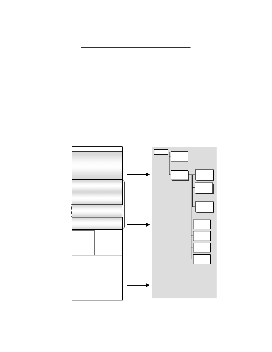
- 157 -
Appendix F Notes on Conversion to FlashPix
The data recording method in this standard makes it possible to convert from Exif to FlashPix format with no loss of
image quality, and retaining all attribute information. A file that is thus designed from the start for conversion to
FlashPix is called a FlashPix-Ready (FPXR) file.
There are three main FlashPix- Ready functions:
•
All Exif tag information is mapped to the FlashPix Image Info Property Set,
•
APP2 extended data can be converted to FlashPix extensions,
•
JPEG images can be converted to the FlashPix tile structure without image quali ty loss, making
use of restart markers.
Fig. 51 illustrates the conversion process.
Fig. 51 Conversion from Exif to FlashPix
Exif (Version 2.0)
SOI
APP1
(Exif data)
JPEG
Table
JPEG
Compressed
Data
(include Restart Marker)
APP2
(Contents List Data Area)
APP2
(Stream Data Area n)
APP2
(Stream Data Area 0)
DQT
DHT
DRI
SOF
SOS
EOI
Exif Tag
Information
to
Image info
Property
Set
FPXR
Application
Segment
to
FPX
Data
Stream
JPEG
Image
to
Tiled JPEG
Image
(Loss-less
Conversion)
FlashPi
x
Root
Property
Set
Image
Object
Image
Data res.0
Image
Data res.1
Image
Data res.n
Summary
Info.
CompObj
Stream
Image
Info.
Extension
List
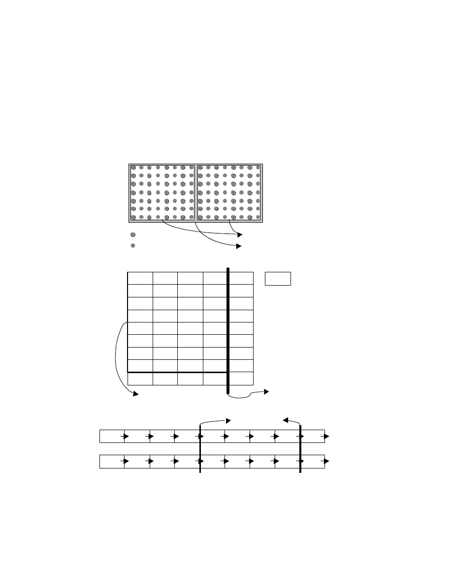
- 158 -
F.1 Converting Image Data
FlashPix compressed image data consists of JPEG-compressed 64 x 64-pixel tiles. Converting JPEG images without
restart markers to FlashPix images requires that the JPEG data be expanded and re-compressed, which can lead to
image quality loss. By inserting restart markers at 64-pixel Interoperability, FlashPix images of the maximum
resolution can be generated simply by rearranging the JPEG-compressed data.
Fig. 52 shows how compressed data is rearranged using restart markers.
Fig. 52 Conversion to FlashPix Using Restart Markers
Y DCT Block (8x8)
CrCb DCT Block (8x8)
Y,Cb,Cr pixel
Y pixel
(a) MCU (4:2:2)
(0,0)
(0,1)
(0,2)
(0,3)
(0,4)
(0,5)
(0,6)
(0,7)
(0,8)
(0,0)
(0,1)
(0,2)
(0,3)
(1,0)
(1,1)
(1,2)
(1,3)
(2,0)
(c) Recording order
FPXR(JPEG)
FlashPix
Restart Marker
MCU
(4:2:2)
(0,0)
(0,1)
(0,2)
(0,3)
(0,4)
(1,0)
(1,1)
(1,2)
(1,3)
(1,4)
(2,0)
(2,1)
(2,2)
(2,3)
(2,4)
(3,0)
(3,1)
(3,2)
(3,3)
(3,4)
(4,0)
(4,1)
(4,2)
(4,3)
(4,4)
(5,0)
(5,1)
(5,2)
(5,3)
(5,4)
(6,0)
(6,1)
(6,2)
(6,3)
(6,4)
(7,0)
(7,1)
(7,2)
(7,3)
(7,4)
(8,0)
(8,1)
(8,2)
(8,3)
(8,4)
(x,y)
1 Tile block (64x64)
(b) Tile block
Restart Marker
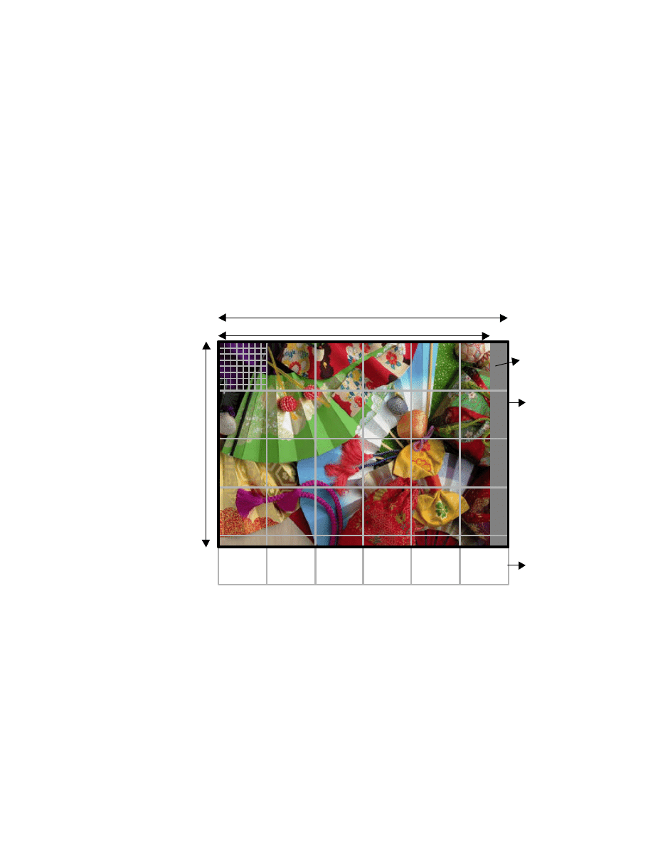
- 159 -
Recording of restart markers is optional, and conversion to FlashPix is possible without them; but conversion
without restart markers may result in some image quality loss and require a longer processing time.
In order for restart markers to be inserted at 64-pixel Interoperability, the image data width must be an exact
multiple of 64. Therefore the valid image width is recorded as tag information (PixelXDimension), and the JPEG
compressed data is recorded with the valid image padded to the right to make it an exact multiple of 64 (see section
2.8.1 ).
As in the FlashPix standard, padding is used where necessary to achieve exact multiples of 64; and when converting
to FlashPix, the padding data on the right can be treated in the same way as valid image data.
If the image height is not an exact multiple of 64, Exif files are not padded; so when converting to FlashPix it is
necessary to pad the bottom edge of the image.
Fig. 53 Image Size Restrictions
SOF Y
=
PixelYDimension
(APP1)
Padding Data
SOF X
PixelXDimension (APP1)
JPEG Data
64 x64 Block
(FPX tile)

- 160 -
F.2 Converting Tag Data
When Exif attribute information is converted to FlashPix, a one-to-one conversion can be made to the Property
Set used to record FlashPix attributes. The rules for converting from each kind of Exif tag to the FlashPix
PropertySet are given in the tables below (conversion of GPS Info tags is to be determined later).
Table 50 Conversion between Exif Tags and FlashPix Property Set ( 1) ( TIFF Tags)
Exif
FPX
Tag Code
Field Name
Dec
Hex
Property Set
Group
Name
ImageWidth
256
100
-
-
-
ImageLength
257
101
-
-
-
BitsPerSample
258
102
-
-
-
Compression
259
103
-
-
-
PhotometricInterpretation
262
106
-
-
-
ImageDescription
270
10E
Image Info
Content Description
Caption text
Make
271
10F
Image Info
Camera Information
Camera manufacturer name
Model
272
110
Image Info
Camera Information
Camera model name
StripOffsets
273
111
-
-
-
Orientation
274
112
Transform
-
Spatial Orientation
SamplesPerPixel
277
11 5
-
-
-
RowsPerStrip
278
116
-
-
-
StripByteCounts
279
117
-
-
-
XResolution
282
11A
Image Contents
Primary description
Default display width
YResolution
283
11B
Image Contents
Primary description
Default display height
PlanarConfiguration
284
11C
-
-
-
ResolutionUnit
296
128
Image Contents
Primary description
Display height/width units
TransferFunction
301
12D
-
-
-
Software
305
131
Image Info
File source
Software Name
DateTime
306
132
Ignore
Ignore
Ignore
Artist
306
13B
Image Info
Intellectual Property
Authorship
WhitePoint
318
13E
-
-
-
PrimaryChromaticities
319
13F
-
-
-
YCbCrCoefficients
529
211
-
-
-
YCbCrSubSampling
530
212
-
-
-
YCbCrPositioning
531
213
Ignore
Ignore
Ignore
ReferenceBlackWhite
532
214
-
-
-
Copyright
33432 8298
Image Info
Intellectual Property
Copyright message
Exif IFD Pointer
34665 8769
-
-
-
GPS Info IFD Pointer
34853 8825
-
-
-
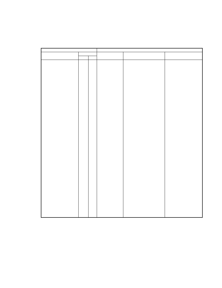
- 161 -
Table 51 Conversion between Exif Tags and FlashPix Property Set ( 2) (Exif Private Tags )
Exif
FPX
Tag Code
Field N a m e
Dec
Hex
Property Set
Group
Name
ExposureTime
33434 829A
Image Info
Per Picture Camera Setting
Exposure time
FNumber
33437 829D
Image Info
Per Picture Camera Setting
F-number
ExposureProgram
34850 8822
Image Info
Per Picture Camera Setting
Exposure program
Spectral Sensitivity
34852 8824
Image Info
Digital Camera Characterization
Spectral sensitivity
ISOSpeedRatings
34855 8827
Image Info
Digital Camera Characterization
ISO speed ratings
OECF
34857 8829
Image Info
Digital Camer a Characterization
OECF
ExifVersion
36864 9000
-
-
-
DateTimeOriginal
36867 9003
Image Info
Content Description
Date of the original image
Image Info
Per Picture Camera Setting
Capture date
DateTimeDigitized
36868 9004
Summary Info
-
Create date/tim e
ComponentsConfiguration 37121 9101
Ignore
Ignore
Ignore
CompressedBitsPerPixel 37122 9102
Ignore
Ignore
Ignore
ShutterSpeedValue
37377 9201
Image Info
Per Picture Camera Setting
Exposure time
ApertureValue
37378 9202
Image Info
Per Picture Camera Setting
F-number
BrightnessValue
37379 9203
Image Info
Per Picture Camera Setting
Brightness value
ExposureBiasValue
37380 9204
Image Info
Per Picture Camera Setting
Exp osure bias value
MaxApertureValue
37381 9205
Image Info
Per Picture Camera Setting
Maximum aperture value
SubjectDistance
37382 9206
Image Info
Per Picture Camera Setting
Subject distance
MeteringMode
37383 9207
Image Info
Per Picture Camera Setting
Metering mode
LightSource
37384 9208
Image Info
Per Picture Camera Setting
Scene illuminan t
Flash
37385 9209
Image Info
Per Picture Camera Setting
Flash
Image Info
Per Picture Camera Setting
Flash return
FocalLength
37386 920A
Image Info
Per Picture Camera Setting
Focal length
MakerNote
37500 927C
-
-
-
UserComment
37510 9286
Image Info
Content description
Content description note
SubSecTime
37520 9290
Ignore
Ignore
Ignore
SubSecTimeOriginal
37521 9291
Image Info
Content Description
Date of the original image
Image Info
Per Picture Camera Setting
Capture date
SubSecTimeDigitized
37522 9292
Summary Info
-
Create date/time
FlashPixVersion
40960 A000
-
-
-
ColorSpace
40961 A001
Image Contents
resolution description
Subimage color
PixelXDimension
40962 A002
Image Contents
Primary description
Highest resolution width
PixelYDimension
40963 A003
Image Contents
Primary description
Highest resolution height
RelatedSoundFile
40964 A004
-
-
-
FlashEnergy
41483 A20B
Image Info
Per Picture Camera Setting
Flash Energy
SpatialFrequencyR esponse 41484 A20C
Image Info
Digital Camera Chara cterization Spatial frequency response
FocalplaneXR esolution 41486 A20E
Image Info
Digital Camera Characterization
Focal plane X resolution
FocalplaneYR esolution 41487 A20F
Image Info
Digital Camera Characterization
Focal plane Y resolution
Focalplane R esolutionU nit 41488 A210
Image Info
Digital Camera Characterization Focal plane resolution unit
Subject Location
41492 A214
Image Info
Per Picture Camera Setting
Subject location
ExposureIndex
41493 A215
Image Info
Per Picture Camera Setting
Exposure index
Sensing Method
41495 A217
Image Info
Digital Camera Characterization
Sensing method
FileSource
41728 A300
Image Info
File Source
File source
SceneType
41729 A301
Image Info
File Source
Scene type
CFAPattern
41730 A302
Image Info
Digital Camera Characterization
CFA pattern
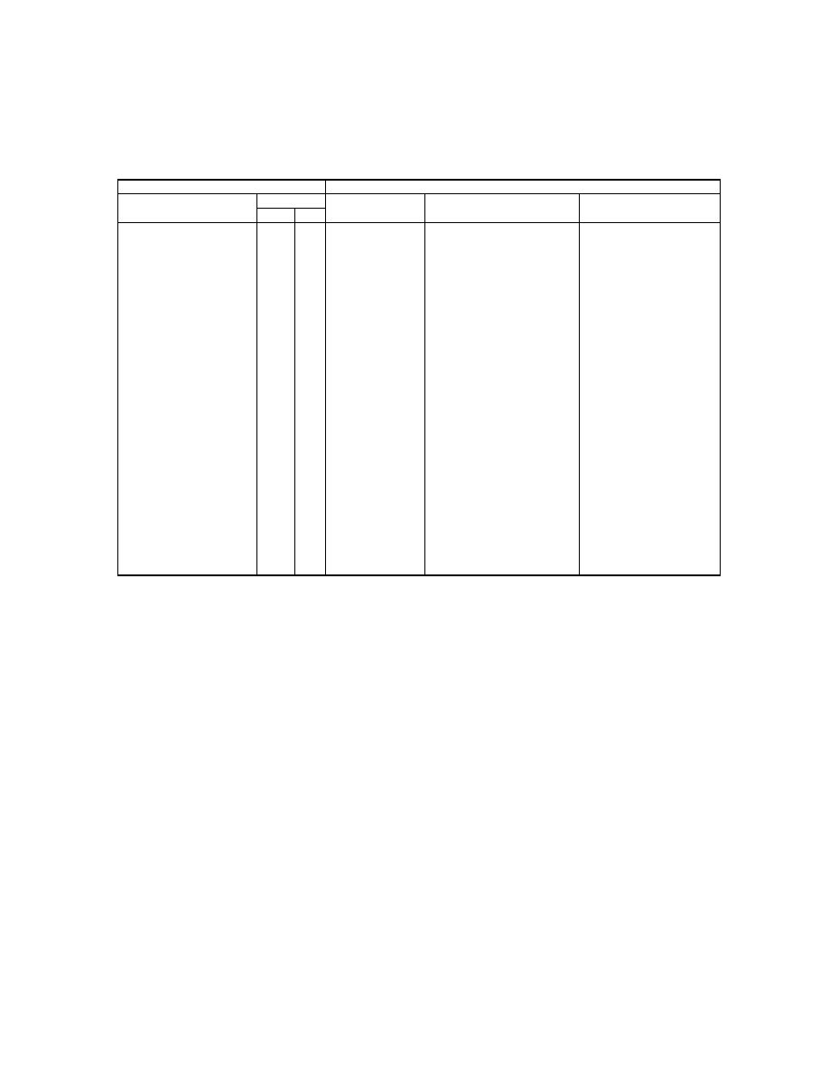
- 162 -
Table 52 Conversion between Exif Tags and FlashPix Property Set (3) (GPS Info Tags)
Exif
FPX
Tag Code
Field Name
Dec
Hex
Property Set
Group
Name
GPSVersionID
0
0
GPS Info extension
-
GPSVersionID
GPSLatitudeRef
1
1
GPS Info extension
-
GPSLatitudeRef
GPSLatitude
2
2
GPS Info extension
-
GPSLatitude
GPSLongitudeRef
3
3
GPS Info extension
-
GPSLongitudeRef
GPSLongitude
4
4
GPS Info extension
-
GPSLongitude
GPSAltitudeRef
5
5
GPS Info extension
-
GPSAltitudeRef
GPSAltitude
6
6
GPS Info extension
-
GPSAltitude
GPSTimeStamp
7
7
GPS Info extension
-
GPSTimeStamp
GPSSatellites
8
8
GPS Info extension
-
GPSSatellites
GPSStatus
9
9
GPS Info extension
-
GPSStatus
GPSMeasureMode
1 0
A
GPS Info extension
-
GPSMeasureMode
GPSDOP
11
B
GPS Info extension
-
GPSDOP
GPSSpeedRef
1 2
C
GPS Info extension
-
GPSSpeedRef
GPSSpeed
1 3
D
GPS Info extension
-
GPSSpeed
GPSTrackRef
1 4
E
GPS Info extension
-
GPSTrackRef
GPSTrack
1 5
F
GPS Info extension
-
GPSTrack
GPSImgDirectionRef
1 6
1 0
GPS Info extension
-
GPSImgDirectionRef
GPSImgDirection
1 7
11
GPS Info extension
-
GPSImgDirection
GPSMapDatum
1 8
1 2
GPS Info extension
-
GPSMapDatum
GPSDestLatitudeRef
1 9
1 3
GPS Info extension
-
GPSDestLatitudeRef
GPSDestLatitude
2 0
1 4
GPS Info extension
-
GPSDestLatitude
GPSDestLongitudeRef
2 1
1 5
GPS Info extension
-
GPSDestLongitudeRef
GPSDestLongitude
2 2
1 6
GPS Info extension
-
GPSDestLongitude
GPSDestBearingRef
2 3
1 7
GPS Info extension
-
GPSDestBearingRef
GPSDestBearing
2 4
1 8
GPS Info extension
-
GPSDestBearing
GPSDestDistanceRef
2 5
1 9
GPS Info extension
-
GPSDestDistanceRef
GPSDestDistance
2 6
1 A
GPS Info extension
-
GPSDestDistance
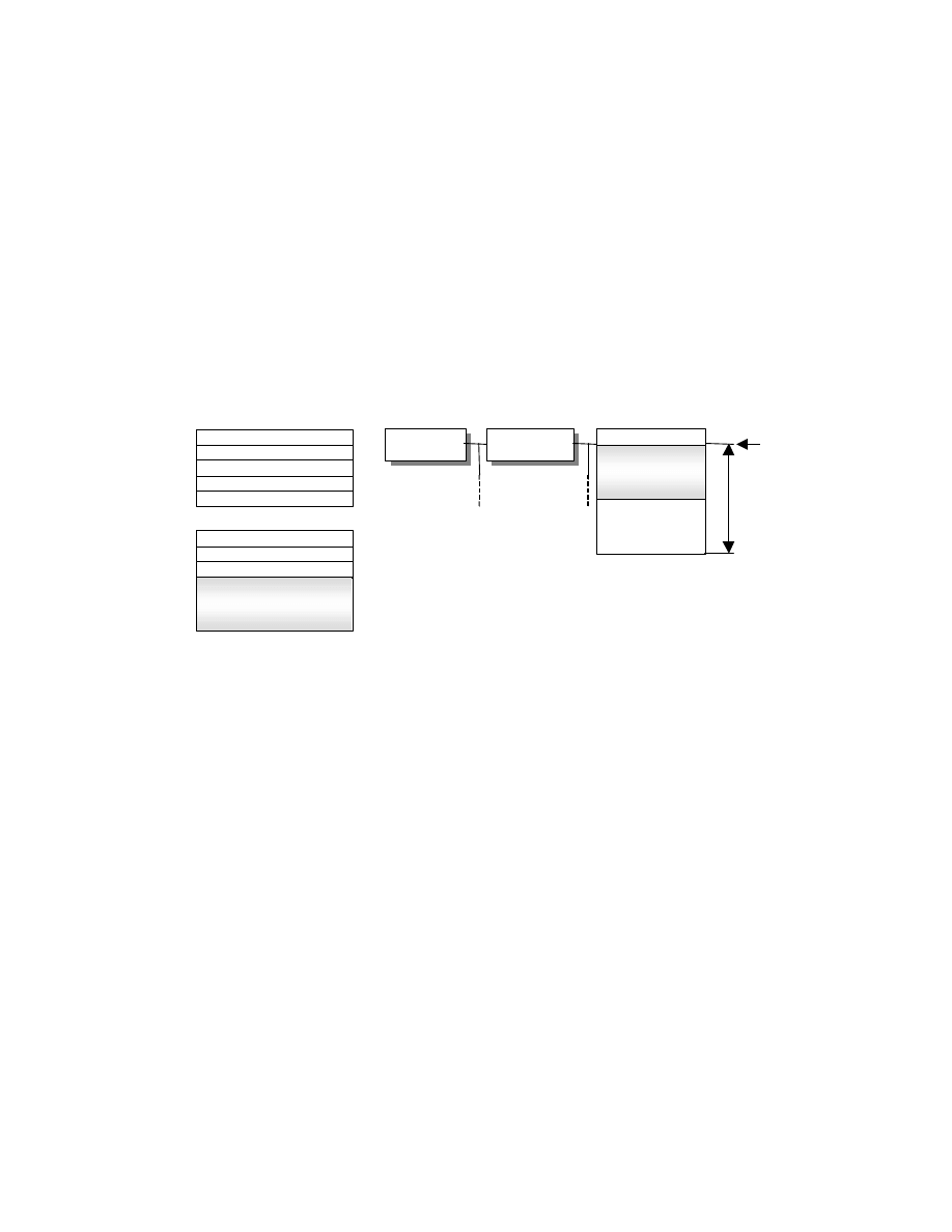
- 163 -
F.3 Converting to FlashPix Extensions (APP2)
The extended data recorded in APP2 marker segments can be converted readily to FlashPix extensions.
First of all, Fig. 54 shows the conversion process when APP2 is recorded as one Interoperability per stream of data.
An area with data size of 8000.H, Default value 00.H is allocated to the stream name "/¥005MyPropertySet" (¥005
means 005.H) in the FlashPix file Structured Storage structure, and the stream data recorded in APP2-2 is copied to
offset 00000000.H, that is, the start of the allocated area.
Fig. 54 Conversion to FlashPix Extensions ( 1)
Offset
0x00000000
Full FlashPix Stream
Data size
0x8000
Stream data
Source image
Object
Source image
Object
FlashPix
root
FlashPix
root
Default value
0x00
Number of Entry = 1
Default value = 0x00
Data size = 0x8000
Contents List
Offset = 0x00000000
Stream data
Index = 0x00
APP2-1
APP2-2
Exif Version 2.0
Stream data
Path “/¥005MyPropertySet”
¥005MyPropertySet
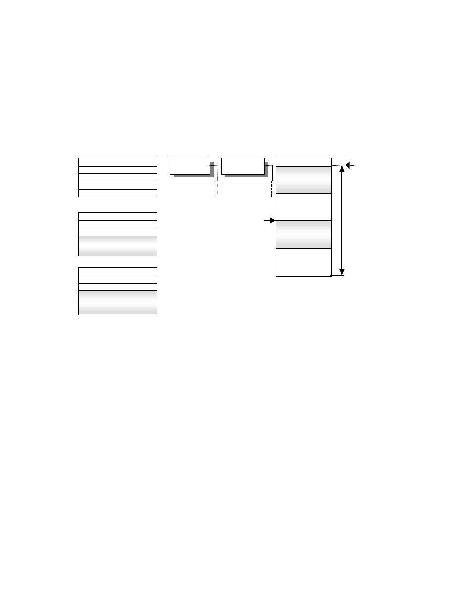
- 164 -
Next, Fig. 55 shows the conversion process when one Interoperability per two streams of data is recorded in APP2.
This time an area with data size of 10000.H, Default value 00.H is allocated to the stream name
"/¥005MyPropertySet" in the FlashPix file Structured Storage structure, and the stream data recorded in APP2-2 is
copied to offset 00000000.H, that is, the start of the allocated area, while the stream data recorded in APP2-3 is
copied starting from offset 00008000.H.
Fig. 55 Conversion to FlashPix Extensions (2)
Offset A= 0x00000000
Stream data A
Stream data
APP2-2
Index = 0x00
Offset B= 0x00008000
Stream data B
Stream data
APP2-3
Index = 0x00
Path”/¥005MyPropertySet”
Number of Entry = 1
Data size = 0x10000
Contents List
APP2-1
Exif Version 2.0
Default value = 0x00
Full FlashPix Stream
Data size
0x10000
Stream data A
Source image
Object
Source image
Object
FlashPix
root
FlashPix
root
Default value
0x00
¥005MyPropertySet
Stream data B
Default value
0x00
Offset B
0x00008000
Offset A
0x00000000
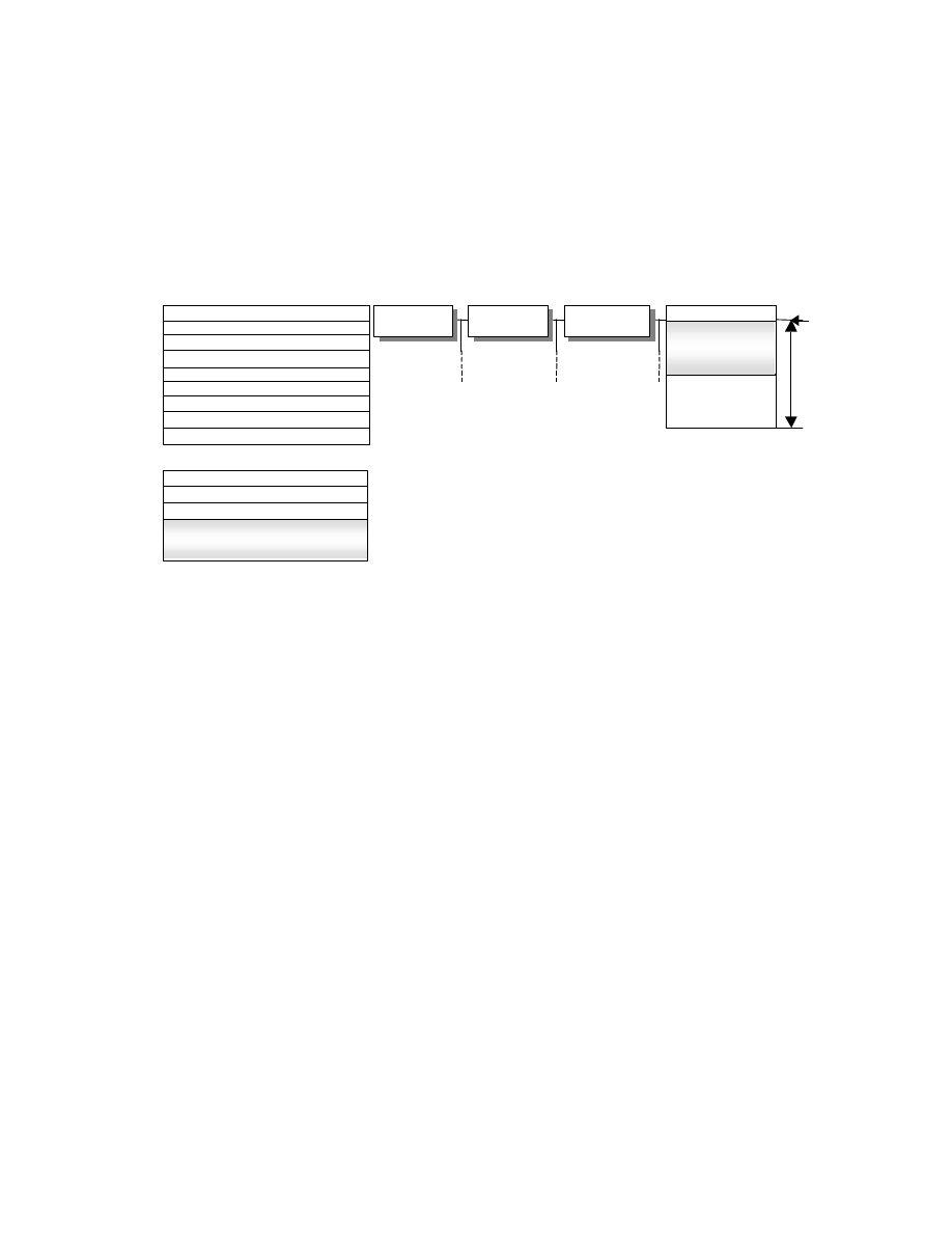
- 165 -
Finally, Fig. 56 shows an example of conversion when 2 Interoperability per stream of data are recorded in APP2.
Here a data size of 8000.H, Default value 00.H is allocated to the stream name "MyPropertySet" Interoperability the
storage name "¥005MyStorage" in the FlashPix file Structured Storage structure, and the stream data recorded in
APP2-2 is copied to offset 00000000.H, that is, the start of the allocated area.
Fig. 56 Conversion to FlashPix Extensions ( 3)
Offset A= 0x00000000
Stream data
Stream data
APP2-2
Index = 0x00
Full FlashPix Stream
Data size
0x8000
Stream data
MyStrage
MyStorage
FlashPix
root
FlashPix
root
Default value
0x00
¥005MyPropertySet
Offset B
0x00008000
Source image
Object
Source image
Object
Path
“
MyStorage
”
Number of Entry = 2
Data size = 0xFFFFFFFF
Contents List
APP2-1
Exif Version2.0
Default value = 0x00
ClassID = 42
Data size = 0x8000
Default value = 0x00
Path”/MyStorage/¥005MyPropertySet”

- 166 -
References
i
Digital Still Camera Image File Format Standard (Exif) Version 1.0, October 1995, Japan Electronic Industry
Development Association.
i i
Digital Still Camera Image File Format Standard (Exif) Version 1.1, May 1997, Japan Electronic Industry
Development Association.
i i i
Digital Still Camera Image File Format Standard (Exif) Version 2.0, Nov 1997, Japan Electronic Industry
Development Association.
i v
ISO/IEC 10918- 1 / ITU-T Recommendation T.81 information technology - Digital compression and coding of
continuous -tone still images - Requirements and guide- lines
v
TIFF Revision 6.0 Final, June 3, 1992, AldusCorporation.
v i
FlashPix Format Specification Version 1.0, September 11, 1996, Eastman Kodak Company.
vii
New Multimedia Data Types and Data Techniques, 1996, Microsoft Corporation.
v i i i
ITU- T G.711, Pulse code modulation (PCM) of Voice Frequencies.
i x
Recommended Practices for Enhancing Digital Audio Compatibility in Multimedia Systems Revision 3.00, October
21, 1992, Interoperability Multimedia Association(IMA)
x
JIS X 0208:1990 Code of the Japanese graphic character set for information Interoperability.
x i
ITU- T T.50 (09/92) Interoperability Reference Alphabet (IRA) (Formerly Interoperability Alphabet No.5 or IA5)
xii
Unicode Standard, The Unicode Consortium, 1991, Addison- Wesley.
x i i i
New Standard Practice for the Electronic Interoperability of Color and Appearance Data, ASTM Technical
Committee
xiv
ISO 12232, Photography-Electronic still picture cameras-Determination of ISO speed.
x v
ISO 14524, Photography-Electronic still picture cameras-Methods for measuring the opto- electronic conversion
functions.
xvi
ISO 12233, Photography-Electronic still picture cameras-Resolution measurements.
xvii
IMA Digital Audio Doc- Pac, 1992, Interoperability Multimedia Association
x v i i i
IEC TC100, 100/43/NP: Colour measurement and management in multimedia systems and equipment, Part 2.1 of
the approved project 61966: Colour management in multimedia systems - Default RGB colour space - sRGB
(Interoperability discussion)
xix
ITU- R BT.709, Basic Parameter Values for the HDTV Standard for the Studio and for Interoperability Programm
Exchange.
x x
ITU- R.BT.601, Encoding Parameters of Digital Television for Studios.
Wyszukiwarka
Podobne podstrony:
[Filmmaking] Screenwriting BBC screenplay format for films
WD Model Number Format for OEM and Distribution Channels 2579 001028
Nowy standard dla aparatów formatu DX NIKKOR AF S DX 35 mm f 1,8G
USITT DMX512 A Asynchronous Serial Digital Data Transmission Standard
Get image file from floppy disk
Grepstad, Jon Building a Large Format Camera Plans and Instructions for Building a 4 X 5 Monorail
Touchstone File Format Specification v2 0
New Lumix Digital Camera
Matlab 7 MAT File Format
standard HL7
Metodologia SPSS Zastosowanie komputerów Golański Standaryzacja
standaryzacja w geomatyce
Wykł 1 Omówienie standardów
Złote standardy w diagnostyce chorób układowych 3
więcej podobnych podstron