Zusatzachse 7 oder 7/8 12.05.00 en
CONTROL CABINET
KR C2 edition2005
External Axis 7 or 7/8
Option 00--129--758 / 760 / 763
Customer Documentation
Issued: 19 Jan 2006
Version: 00

Zusatzachse 7 oder 7/8 12.05.00 en
e
Copyright
2005
KUKA Roboter GmbH
Zugspitzstrasse 140
D--86165 Augsburg
This documentation or excerpts therefrom may not be reproduced or disclosed to third parties without the express permission of the
publishers.
Other functions not described in this documentation may be operable in the controller. The user has no claim to these functions,
however, in the case of a replacement or service work.
We have checked the content of this documentation for conformity with the hardware and software described. Nevertheless,
discrepancies cannot be precluded, for which reason we are not able to guarantee total conformity. The information in this
documentation is checked on a regular basis, however, and necessary corrections will be incorporated in subsequent editions.
Subject to technical alterations without an effect on the function.
3 of 12
Zusatzachse 7 oder 7/8 12.05.00 en
Inhaltsverzeichnis
1
Introduction
5
. . . . . . . . . . . . . . . . . . . . . . . . . . . . . . . . . . . . . . . . . . . . . . . . .
1.1
Use
5
. . . . . . . . . . . . . . . . . . . . . . . . . . . . . . . . . . . . . . . . . . . . . . . . . . . . . . . . . . . . . . . . . . . . . . . . . .
1.2
Structure
5
. . . . . . . . . . . . . . . . . . . . . . . . . . . . . . . . . . . . . . . . . . . . . . . . . . . . . . . . . . . . . . . . . . . . .
2
Safety
6
. . . . . . . . . . . . . . . . . . . . . . . . . . . . . . . . . . . . . . . . . . . . . . . . . . . . . .
2.1
Fundamentals
6
. . . . . . . . . . . . . . . . . . . . . . . . . . . . . . . . . . . . . . . . . . . . . . . . . . . . . . . . . . . . . . . . .
2.2
Additional safety instructions for the “External axis 7 or 7/8”
6
. . . . . . . . . . . . . . . . . . . . . . . . . .
2.3
Liability
7
. . . . . . . . . . . . . . . . . . . . . . . . . . . . . . . . . . . . . . . . . . . . . . . . . . . . . . . . . . . . . . . . . . . . . . .
2.4
Designated use
7
. . . . . . . . . . . . . . . . . . . . . . . . . . . . . . . . . . . . . . . . . . . . . . . . . . . . . . . . . . . . . . . .
3
Product description
8
. . . . . . . . . . . . . . . . . . . . . . . . . . . . . . . . . . . . . . . . .
3.1
Control cabinet, overview
8
. . . . . . . . . . . . . . . . . . . . . . . . . . . . . . . . . . . . . . . . . . . . . . . . . . . . . . .
3.2
Connection panel
9
. . . . . . . . . . . . . . . . . . . . . . . . . . . . . . . . . . . . . . . . . . . . . . . . . . . . . . . . . . . . . .
3.2.1
Safety
9
. . . . . . . . . . . . . . . . . . . . . . . . . . . . . . . . . . . . . . . . . . . . . . . . . . . . . . . . . . . . . . . . . . . . . . . .
3.2.2
Overview
10
. . . . . . . . . . . . . . . . . . . . . . . . . . . . . . . . . . . . . . . . . . . . . . . . . . . . . . . . . . . . . . . . . . . . .
4
Connector pin allocation
11
. . . . . . . . . . . . . . . . . . . . . . . . . . . . . . . . . . . . .
4.1
Motor connectors X7.1 and X7.2, size 1
11
. . . . . . . . . . . . . . . . . . . . . . . . . . . . . . . . . . . . . . . . . . .
4.2
Motor connector X7.1, size 2
12
. . . . . . . . . . . . . . . . . . . . . . . . . . . . . . . . . . . . . . . . . . . . . . . . . . . .
External Axis 7 or 7/8
4 of 12
Zusatzachse 7 oder 7/8 12.05.00 en

1
Introduction
5 of 12
Zusatzachse 7 oder 7/8 12.05.00 en
1
Introduction
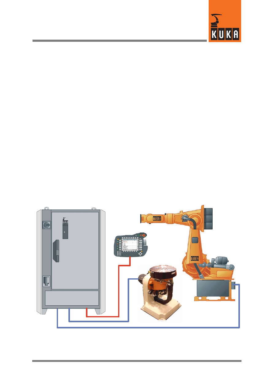
This option enables the implementation of freely movable and positionable
additional drives: e.g. turntables, single--axis positioners, loading stations, etc.
1.1
Use
If only axis 7 is installed, size 1 drive module (08/16/32) or size 2 (48/64) can be
used. If both external axes 7 and 8 are fitted, only the size 1 drive module is used.
External axis 7, Size 1
A connection for axis 7 is provided by connector X7.1.
External axis 8, Size 1
A connection for axis 8 is provided by connector X7.2.
External axis 7, Size 2:
A connection for axis 7 (A0 motor) is provided by connector X7.1.
1.2
Structure
External axes 7 and 8
G
Motor connector X7.1
G
Motor connector X7.2
G
Drive module N7 Size 1
G
Drive module N8 Size 1
G
Installation and fastening materials
only external axis 7
G
Motor connector X7.1
G
Drive module N7 Size 1 or Size 2
G
Installation and fastening materials
External Axis 7 or 7/8
6 of 12
Zusatzachse 7 oder 7/8 12.05.00 en
2
Safety
2.1
Fundamentals
Warning!
Failure to observe these safety instructions could result in injury or a fatal
accident and/or damage to the robot system or other property!
G
All pertinent safety regulations as well as the booklet [Safety and Installation
Instructions] are to be observed when working on the system.
G
The KUKA safety chapter [KRC Safety, General] is supplied with the robot
system and must be read and understood before commencing work.
G
The safety instructions in the KR C2 edition2005 Operating Handbook must
be observed.
G
Before connection, testing and installation work, always refer to the
accompanying circuit diagram.
2.2
Additional safety instructions for the “External axis 7 or 7/8”
G
Installation, exchange and service work on this option or individual
components thereof may be performed only by qualified personnel specially
trained for this purpose and acquainted with the risks involved.

2
Safety (continued)
7 of 12
Zusatzachse 7 oder 7/8 12.05.00 en
2.3
Liability
This option is designed and built using state--of--the--art technology and in
accordance with the recognized safety rules. Nevertheless, improper installation
of this option or its employment for a purpose other than the intended one may
constitute a risk to life and limb of operating personnel or of third parties, or cause
damage to or failure of the control cabinet, resulting in damage to or failure of the
entire robot system and other material property.
The option “External Axis 7 or 7/8” may only be used in technically perfect condition
in accordance with its designated use and only by safety--conscious persons who
are fully aware of the risks involved in its operation. Connection and use must be
carried out in compliance with this documentation.
2.4
Designated use
Using this option for any purpose other than or additional to that described in
Section 1.1 is considered contrary to its designated use. The manufacturer cannot
be held liable for any damage resulting from such use.
The risk lies entirely with the user.
No liability can be accepted if these directions are disregarded.
External Axis 7 or 7/8
8 of 12
Zusatzachse 7 oder 7/8 12.05.00 en
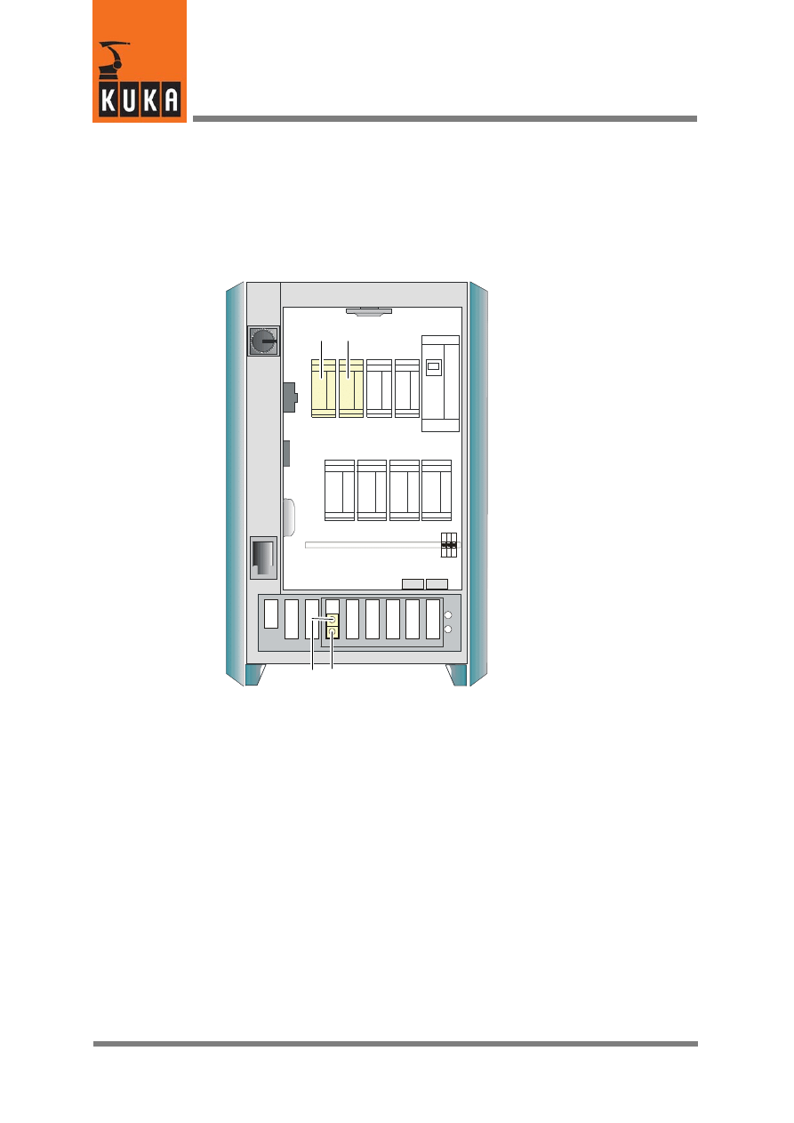
3
Product description
3.1
Control cabinet, overview
3
4
1
2
1
Drive module N8
2
Drive module N7
3
Motor connector X7.1
4
Motor connector X7.2
Abb. 1 Example: Control cabinet with external axes 7 and 8
3
Product description (continued)
9 of 12
Zusatzachse 7 oder 7/8 12.05.00 en
3.2
Connection panel
All the connectors on the connection panel are plug--and--socket connections as
defined by VDE 0627.
Plug--and--socket connections must not be plugged or unplugged while the
controller is operational (i.e. energized).
Requirements:
G
Qualified technical personnel (skilled workers) trained in the handling of
systems and machines.
3.2.1
Safety
Warning!
Before the plug--and--socket connections are plugged or unplugged, the
controller and the cables concerned must be deenergized.
External Axis 7 or 7/8
10 of 12
Zusatzachse 7 oder 7/8 12.05.00 en
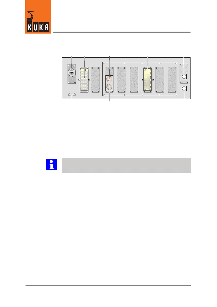
3.2.2
Overview
1
2
5
3
6
7
8
4
1
XS1 Cable inlet for power supply connection
2
X20
Motor connector, axes 1 to 6
3
X7.2 Motor connector, external axis 8
4
X11
Customer interface
5
X19 KCP connection
6
X21
Data cable
7
X7.1 Motor connector, external axis 7
8
PE
Ground conductor connection
Abb. 2 Configuration example: Motor connectors, external axes
Further information
Depending on the drive class and cabinet option, the slot assignments of the
connectors and the motor connector design may differ from those shown.
All contactor, relay and valve coils that are connected to the robot controller by the
user must be equipped with suitable suppressor diodes (RC elements and VCR
resistors are not suitable).
4
Connector pin allocation
11 of 12
Zusatzachse 7 oder 7/8 12.05.00 en
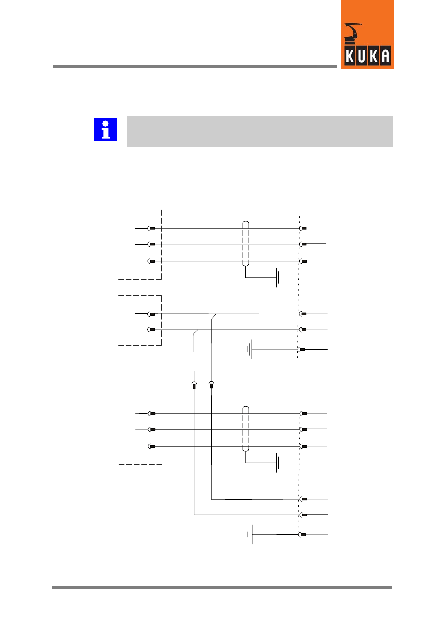
4
Connector pin allocation
Further information
For detailed information about all connections, please refer to the accompany-
ing circuit diagrams.
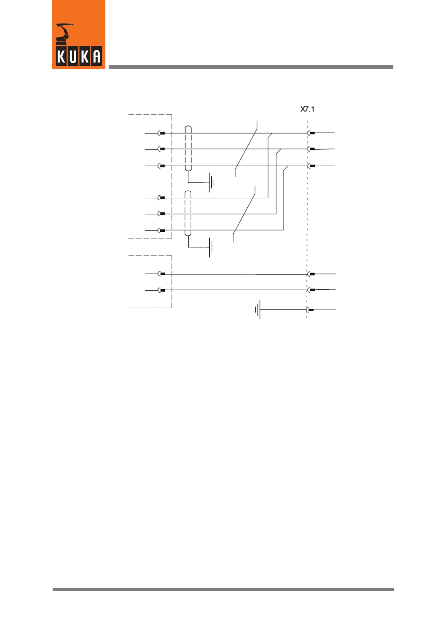
4.1
Motor connectors X7.1 and X7.2, size 1
1
2
6
Motor M7 U1
Motor M7 V1
Motor M7 W1
4
5
+ Brake A7
GND brake
N7
X2
KPS
X12
4
3
2
4
3
Grd. conductor
1
2
6
Motor M8 U1
Motor M8 V1
Motor M8 W1
4
5
+ Brake A8
GND brake
N8
4
3
2
Grd. conductor
X7.2
X7.1
PE
PE
X2
X7.3
External Axis 7 or 7/8
12 of 12
Zusatzachse 7 oder 7/8 12.05.00 en
4.2
Motor connector X7.1, size 2
U
V
W
Motor M7 U1
Motor M7 V1
Motor M7 W1
+
--
+ Brake A7
GND brake
Toroidal core
N7
X2
X3
Toroidal core
KPS
X2
4
3
2
4
3
2
4
3
Ground
1

Index
Index -- i
C
Connectors, 9
D
Drive module N7, 8
Drive module N8, 8
S
Safety instructions, 6
U
Use, 5
X
X7.1, 10
X7.2, 10
Document Outline
Wyszukiwarka
Podobne podstrony:
krc2 ed05 kcp holder en
krc2 ed05 profibus en
krc2 ed05 pci en
krc2 ed05 safetybus en
krc2 ed05 20 A Han6 Power Infeed usa en
krc2 ed05 interbus en
krc2 ed05 devicenet en
KR C2 ed05 Battery Monitoring en
KRC2 ed05 Profibus
krc2 peri en
BA KR C2 ed05 Main Switch with Cover en
Budzik Versa wielkość karty kredytowej instrukcja EN
G2 4 PW EN wn Rys 01
Manual Acer TravelMate 2430 US EN
Ćwiczenie 01 EN DI
eci en
BVSOI 3 001 E en
więcej podobnych podstron