V2.1 18.10.200
Issued: 18.10.2007 Version: 2.1
KUKA Robot Group
Controller Option
Battery Monitoring
KR C2 edition05

© Copyright 2007
KUKA Roboter GmbH
Zugspitzstraße 140
D-86165 Augsburg
Germany
This documentation or excerpts therefrom may not be reproduced or disclosed to third parties without
the express permission of the KUKA ROBOT GROUP.
Other functions not described in this documentation may be operable in the controller. The user has no
claims to these functions, however, in the case of a replacement or service work.
We have checked the content of this documentation for conformity with the hardware and software de-
scribed. Nevertheless, discrepancies cannot be precluded, for which reason we are not able to guaran-
tee total conformity. The information in this documentation is checked on a regular basis, however, and
necessary corrections will be incorporated in the subsequent edition.
Subject to technical alterations without an effect on the function.
KIM-PS4-DOC
V0.4 22.03.200
6 pub de
Battery Monitoring
V2.1 18.10.2007 KRC-OP-KRC2ed05-Akkuueberwachung en

V2.1 18.10.2007 KRC-OP-KRC2ed05-Akkuueberwachung en
Contents
Introduction ......................................................................................................
5
Target group ...................................................................................................................
5
Representation of warnings and notes ...........................................................................
5
Product description .........................................................................................
7
Description of battery monitoring ....................................................................................
7
SITOP DC UPS 15 module .............................................................................................
8
Operating state indication ...............................................................................................
8
Protection and monitoring functions ...............................................................................
9
Setting the DIP switches .................................................................................................
10
Connecting the SITOP DC UPS 15 module ...................................................................
12
Technical data ..................................................................................................
13
Basic data .......................................................................................................................
13
Safety ................................................................................................................
15
KUKA Service ...................................................................................................
17
Requesting support .........................................................................................................
17
KUKA Customer Support ................................................................................................
17
Contents

V2.1 18.10.2007 KRC-OP-KRC2ed05-Akkuueberwachung en
1. Introduction
1
Introduction
1.1
Target group
This documentation is aimed at users with the following knowledge and skills:
Advanced knowledge of electrical and electronic systems
Advanced knowledge of the robot controller
Advanced knowledge of the Windows operating system
1.2
Representation of warnings and notes
Safety
Warnings marked with this pictogram are relevant to safety and must be ob-
served.
Notes
Notes marked with this pictogram contain tips to make your work easier or ref-
erences to further information.
Danger!
This warning means that death, severe physical injury or substantial material
damage will occur, if no precautions are taken.
Warning!
This warning means that death, severe physical injury or substantial material
damage may occur, if no precautions are taken.
Caution!
This warning means that minor physical injuries or minor material damage
may
occur, if no precautions are taken.
Tips to make your work easier or references to further information.

V2.1 18.10.2007 KRC-OP-KRC2ed05-Akkuueberwachung en
2. Product description
2
Product description
2.1
Description of battery monitoring
The SITOP DC UPS 15 module monitors the charge of the back-up batteries.
The batteries are tested at regular intervals during operation and an alarm sig-
nal is generated in the event of a fault. The batteries are kept at full charge. If
the 24 V DC power supply fails or the voltage dips below the set threshold, the
batteries cut in. The green LED in the door (not present in the case of "Battery
Monitoring without LED") indicates that the SITOP DC UPS module is operat-
ing normally.
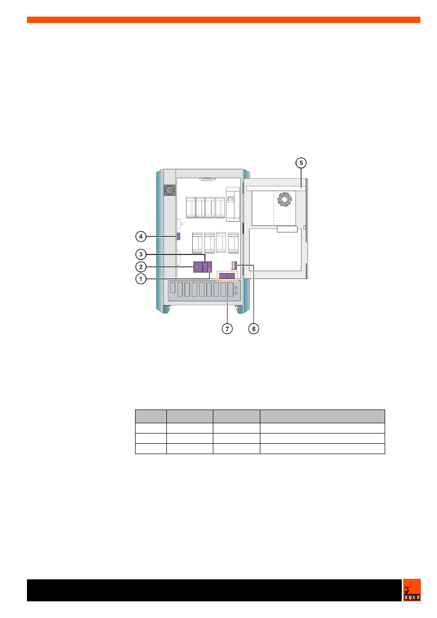
Overview
Fuses
Fig. 2-1: Overview of battery monitoring
1
Blowout fuse F34
5
Green LED V5
2
SITOP DC UPS 15 module
6
Blowout fuse FG3
3
Relay K34
7
Batteries
4
Blowout fuse F33
Item
Fuse
Value in A
Circuit
1
F34
2 A
Fusing for relay K34
4
F33
7.5 A
Input, SITOP DC UPS 15 module
6
FG3
10 A
Battery circuit
V2.1 18.10.2007 KRC-OP-KRC2ed05-Akkuueberwachung en
Battery Monitoring
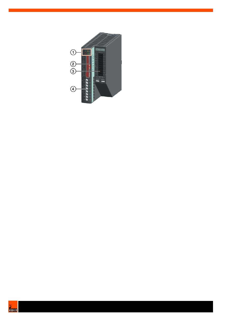
2.2
SITOP DC UPS 15 module
Overview
2.3
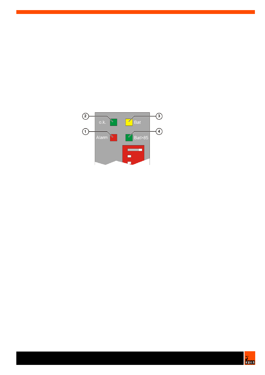
Operating state indication
Description
4 LEDs are used to indicate the following operating states of the SITOP DC
UPS module:
Normal operation
If the input voltage at the SITOP DC UPS module is higher than the set
cut-in threshold, the devices are supplied by the upstream power supply.
The connected batteries are charged. In normal operation, the green LED
(o.k.) is lit and the relay contact X2.2-X2.3 is closed.
> 85% of full charge
If the battery charge is greater than 85%, the green LED (Bat>85) is lit and
the relay contact X2.7-X2.8 is closed.
Back-up operation
If the input voltage is lower than the set cut-in threshold, the devices are
supplied by the batteries. The yellow LED (Bat) is lit and the relay contact
X2.1-X2.2 is closed.
Alarm signal: Back-up not available
If the back-up function is not available, the red LED (Alarm) is lit and the
relay contact X2.4-X2.5 is closed.
The following situations can cause the back-up function to be unavailable
in normal operation:
Operating state Off
No battery connected
Battery defective or polarity reversed
Fig. 2-2: SITOP DC UPS 15 module
1
LED display, operating state
3
Terminals X1
2
DIP switches
4
Terminals X2
V2.1 18.10.2007 KRC-OP-KRC2ed05-Akkuueberwachung en
2. Product description
Open circuit
If the red LED flashes once every 2 seconds, the battery is defective.
Back-up operation is still possible. The specified back-up times can no
longer be maintained, however. The batteries must be exchanged.
If the red LED is lit during back-up operation, the battery voltage has
dropped to < 20.4 V. A forced switch-off is imminent in order to protect the
battery.
The red LED goes out if the batteries have been switched off.
Causes:
Overload
Short-circuit
Exhaustive discharge protection
Back-up time exceeded
The relay contact X2.4-X2.5 remains closed.
2.4
Protection and monitoring functions
Description
The SITOP DC UPS module features the following protection and monitoring
functions:
Battery test
In normal operation, the connected batteries are tested every 4 hours if no
back-up operation or switch-off of the SITOP DC UPS module has oc-
curred. A defective battery is indicated by the flashing red LED (Alarm).
Overcurrent and short-circuit protection
In normal operation and back-up mode, the SITOP DC UPS module is pro-
tected by the internal current limitation. A built-in (and inaccessible) 16 A
fuse protects the SITOP module. The module attempts to restart every 20
seconds.
Exhaustive discharge protection
The batteries may only be discharged to the exhaustive discharge thresh-
old. If the battery is discharged further, this reduces the service life of the
batteries and may destroy them. In order to protect the batteries against
damage, the SITOP DC UPS module is shut down, the state stored, and
the devices disconnected from the batteries, as soon as the battery volt-
age falls below 19 V during back-up operation.
Polarity reversal protection
The SITOP DC UPS module is electronically protected against polarity re-
versal of the input voltage and the batteries.
Fig. 2-3: Operating state indication
1
Red LED "Alarm"
3
Yellow LED "Bat"
2
Green LED "o.k."
4
Green LED "Bat>85"
V2.1 18.10.2007 KRC-OP-KRC2ed05-Akkuueberwachung en
Battery Monitoring
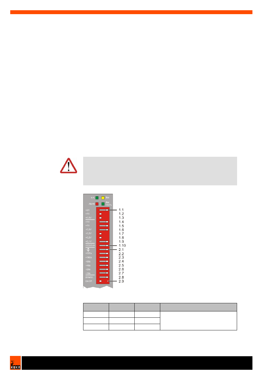
2.5
Setting the DIP switches
Description
The following parameters are set using the DIP switches:
Battery cut-in threshold
If the input voltage drops below the value set as the cut-in threshold, the
SITOP module switches to back-up operation.
End-of-charge voltage
The end-of-charge voltage depends on the battery type and the ambient
temperature.
Charging current
The batteries are charged with constant current until the set end-of-charge
voltage is reached. Observe the specifications of the battery manufacturer
in order to select the optimal setting.
Operating state On/Off
To prevent unintentional discharging of the batteries, the SITOP module
can be switched to the operating state "Off".
Back-up time
Back-up operation is terminated when the set back-up time expires.
Interruption of the output voltage
On expiry of the set back-up time, the output voltage can be interrupted for
5 seconds.
Default setting
Caution!
Incorrect settings reduce the service life of the batteries and may destroy
them. The charging current and end-of-charge voltage must be set in accord-
ance with the following defaut setting (
>>>
2.5 "Setting the DIP switches"
page 10).
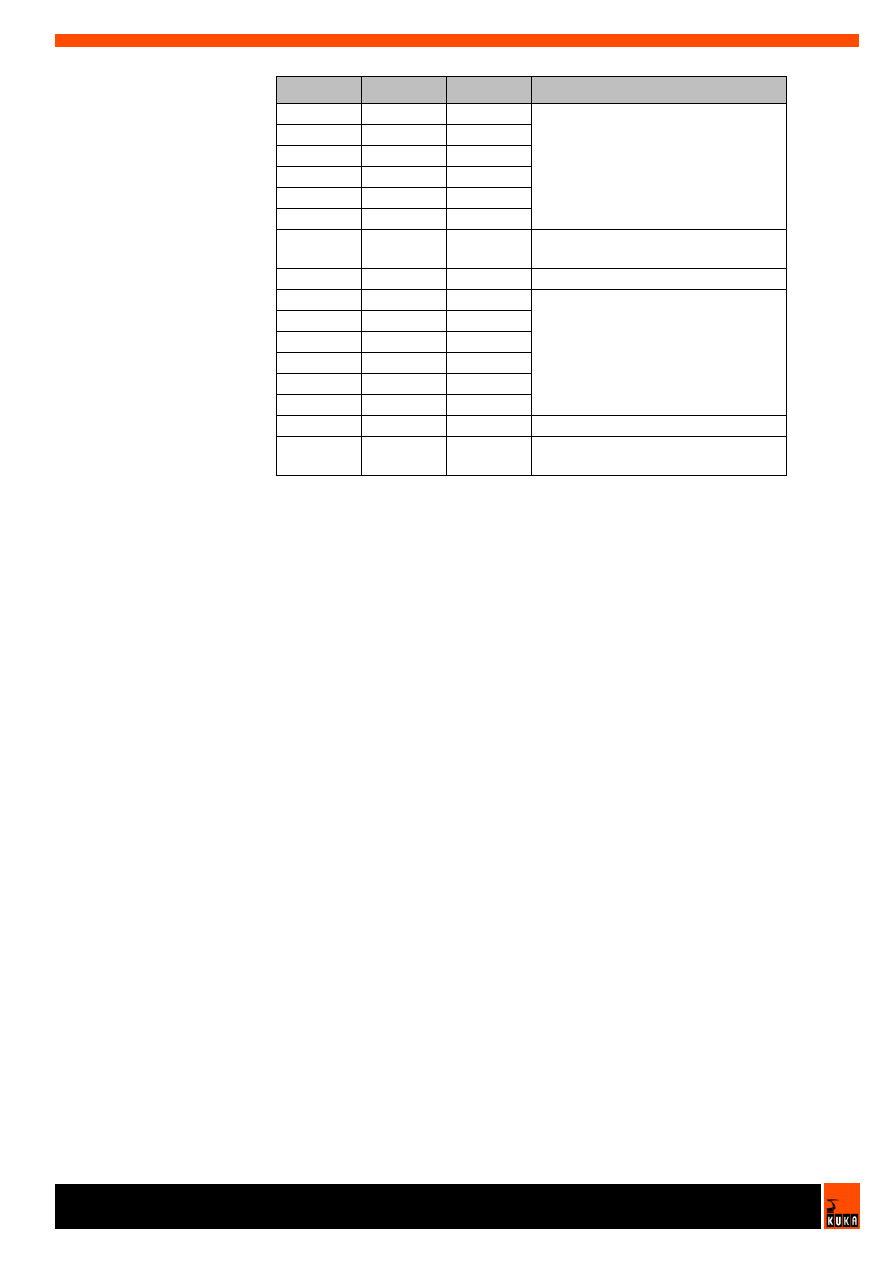
Fig. 2-4: SITOP module DIP switches: default setting
Switch
On/Off
Value
Comments
1.1
Off
+2 V
Threshold for switching to battery
operation: 23.5 V
1.2
On
+1.0 V
1.3
On
+0.5 V
V2.1 18.10.2007 KRC-OP-KRC2ed05-Akkuueberwachung en
2. Product description
1.4
Off
+1.0 V
End-of-charge voltage: 26.7 V
1.5
Off
+1.0 V
1.6
Off
+0.5 V
1.7
On
+0.2 V
1.8
On
+0.2 V
1.9
Off
+0.1 V
1.10
Off
0.35 A /
0.7 A
Charging current: 0.7 A
2.1
Off
t/max.
Back-up time not limited
2.2
Off
+320 s
Back-up time without function
2.3
Off
+160 s
2.4
Off
+80 s
2.5
Off
+40 s
2.6
Off
+20 s
2.7
Off
+10 s
2.8
Off
Gap Out
No interruption of output
2.9
Off
Battery
On/Off
Back-up function deactivated
Switch
On/Off
Value
Comments
V2.1 18.10.2007 KRC-OP-KRC2ed05-Akkuueberwachung en
Battery Monitoring
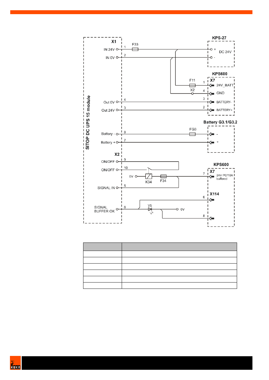
2.6
Connecting the SITOP DC UPS 15 module
Overview
Connector pin
allocation
Fig. 2-5: SITOP DC UPS 15 module, connection
Terminals
Function
X1.1
Input voltage 24 V DC
X1.3
Output voltage 24 V DC
X1.2/X1.4
Input/output voltage 0 V DC
X1.7/X1.8
Battery module 24 V DC
X2.5/X2.6
Signal: back-up not available/available
X2.9/X2.10
On/Off jumper (no jumper = Off)

V2.1 18.10.2007 KRC-OP-KRC2ed05-Akkuueberwachung en
3. Technical data
3
Technical data
3.1
Basic data
Input data
Output data
Load rating of the relay contacts:
DC 60 V / 1 A
AC 30 V / 1 A
Rated input voltage
24 V DC
Working voltage range
22 to 29 V DC
Max. input current at 24 V with battery charging
16.0 A DC
Max. input current at 24 V with charged battery
15.1 A DC
Max. battery current in back-up operation
15.1 A DC
Power dissipation at 24 V with battery charging
approx. 16 W
Power dissipation at 24 V with charged battery
approx. 14 W
Power dissipation in back-up operation
approx. 15 W
Rated output voltage
24 V DC
Rated output current
15 A DC
Output current range
0 - 15 A DC
Output characteristic of
the charging regulator
The battery module is charged with settable
constant current until the set end-of-charge
voltage is reached.
End-of-charge voltage
26.3 to 29.3 V DC
Charging current
0.35 or 0.7 A DC


V2.1 18.10.2007 KRC-OP-KRC2ed05-Akkuueberwachung en
4. Safety
4
Safety
Important remarks
All persons working with the robot system must have read and understood
the robot system documentation, including the safety chapter.
Exchange or service work on this option may only be carried out by KUKA
Roboter GmbH’s Customer Services.
Caution!
Incorrect settings reduce the service life of the batteries and may destroy
them. The charging current and end-of-charge voltage must be set in accord-
ance with the following defaut setting (
>>>
2.5 "Setting the DIP switches"
page 10).


V2.1 18.10.2007 KRC-OP-KRC2ed05-Akkuueberwachung en
5. KUKA Service
5
KUKA Service
5.1
Requesting support
Introduction
The KUKA Robot Group documentation offers information on operation and
provides assistance with troubleshooting. For further assistance, please con-
tact your local KUKA subsidiary.
Information
The following information is required for processing a support request:
Model and serial number of the robot
Model and serial number of the controller
Model and serial number of the linear unit (if applicable)
Version of the KUKA System Software
Optional software or modifications
Archive of the software
Application used
Any external axes used
Description of the problem, duration and frequency of the fault
5.2
KUKA Customer Support
Availability
KUKA Customer Support is available in many countries. Please do not hesi-
tate to contact us if you have any questions.
Argentina
Ruben Costantini S.A. (Agency)
Luis Angel Huergo 13 20
Parque Industrial
2400 San Francisco (CBA)
Argentina
Tel. +54 3564 421033
Fax +54 3564 428877
ventas@costantini-sa.com
Australia
Marand Precision Engineering Pty. Ltd. (Agency)
153 Keys Road
Moorabbin
Victoria 31 89
Australia
Tel. +61 3 8552-0600
Fax +61 3 8552-0605
robotics@marand.com.au
Faults leading to production downtime are to be reported to the local KUKA
subsidiary within one hour of their occurrence.

V2.1 18.10.2007 KRC-OP-KRC2ed05-Akkuueberwachung en
Battery Monitoring
Austria
KUKA Roboter GmbH
Vertriebsbüro Österreich
Regensburger Strasse 9/1
4020 Linz
Austria
Tel. +43 732 784752
Fax +43 732 793880
office@kuka-roboter.at
www.kuka-roboter.at
Belgium
KUKA Automatisering + Robots N.V.
Centrum Zuid 1031
3530 Houthalen
Belgium
Tel. +32 11 516160
Fax +32 11 526794
info@kuka.be
www.kuka.be
Brazil
KUKA Roboter do Brasil Ltda.
Avenida Franz Liszt, 80
Parque Novo Mundo
Jd. Guançã
CEP 02151 900 São Paulo
SP Brazil
Tel. +55 11 69844900
Fax +55 11 62017883
info@kuka-roboter.com.br
Chile
Robotec S.A. (Agency)
Santiago de Chile
Chile
Tel. +56 2 331-5951
Fax +56 2 331-5952
robotec@robotec.cl
www.robotec.cl
China
KUKA Flexible Manufacturing Equipment (Shanghai) Co., Ltd.
Shanghai Qingpu Industrial Zone
No. 502 Tianying Rd.
201712 Shanghai
P.R. China
Tel. +86 21 5922-8652
Fax +86 21 5922-8538
Franz.Poeckl@kuka-sha.com.cn
www.kuka.cn

V2.1 18.10.2007 KRC-OP-KRC2ed05-Akkuueberwachung en
5. KUKA Service
France
KUKA Automatisme + Robotique SAS
Techvallée
6 Avenue du Parc
91140 Villebon s/Yvette
France
Tel. +33 1 6931-6600
Fax +33 1 6931-6601
commercial@kuka.fr
www.kuka.fr
Germany
KUKA Roboter GmbH
Blücherstr. 144
86165 Augsburg
Germany
Tel. +49 821 797-4000
Fax +49 821 797-1616
info@kuka-roboter.de
www.kuka-roboter.de
Hungary
KUKA Robotics Hungaria Kft.
Fö út 140
2335 Taksony
Hungary
Tel. +36 24 501609
Fax +36 24 477031
info@kuka-robotics.hu
India
KUKA Robotics, Private Limited
621 Galleria Towers
DLF Phase IV
122 002 Gurgaon
Haryana
India
Tel. +91 124 4148574
info@kuka.in
www.kuka.in
Italy
KUKA Roboter Italia S.p.A.
Via Pavia 9/a - int.6
10098 Rivoli (TO)
Italy
Tel. +39 011 959-5013
Fax +39 011 959-5141
kuka@kuka.it
www.kuka.it

V2.1 18.10.2007 KRC-OP-KRC2ed05-Akkuueberwachung en
Battery Monitoring
Korea
KUKA Robot Automation Korea Co. Ltd.
4 Ba 806 Sihwa Ind. Complex
Sung-Gok Dong, Ansan City
Kyunggi Do
425-110
Korea
Tel. +82 31 496-9937 or -9938
Fax +82 31 496-9939
info@kukakorea.com
Malaysia
KUKA Robot Automation Sdn Bhd
South East Asia Regional Office
No. 24, Jalan TPP 1/10
Taman Industri Puchong
47100 Puchong
Selangor
Malaysia
Tel. +60 3 8061-0613 or -0614
Fax +60 3 8061-7386
info@kuka.com.my
Mexico
KUKA de Mexico S. de R.L. de C.V.
Rio San Joaquin #339, Local 5
Colonia Pensil Sur
C.P. 11490 Mexico D.F.
Mexico
Tel. +52 55 5203-8407
Fax +52 55 5203-8148
info@kuka.com.mx
Norway
KUKA Sveiseanlegg + Roboter
Bryggeveien 9
2821 Gjövik
Norway
Tel. +47 61 133422
Fax +47 61 186200
geir.ulsrud@kuka.no
Portugal
KUKA Sistemas de Automatización S.A.
Rua do Alto da Guerra n° 50
Armazém 04
2910 011 Setúbal
Portugal
Tel. +351 265 729780
Fax +351 265 729782
kuka@mail.telepac.pt

V2.1 18.10.2007 KRC-OP-KRC2ed05-Akkuueberwachung en
5. KUKA Service
Russia
KUKA-VAZ Engineering
Jushnoje Chaussee, 36 VAZ, PTO
445633 Togliatti
Russia
Tel. +7 8482 391249 or 370564
Fax +7 8482 736730
Y.Klychkov@VAZ.RU
South Africa
Jendamark Automation LTD (Agency)
76a York Road
North End
6000 Port Elizabeth
South Africa
Tel. +27 41 391 4700
Fax +27 41 373 3869
www.jendamark.co.za
Spain
KUKA Sistemas de Automatización S.A.
Pol. Industrial
Torrent de la Pastera
Carrer del Bages s/n
08800 Vilanova i la Geltrú (Barcelona)
Spain
Tel. +34 93 814-2353
Fax +34 93 814-2950
Comercial@kuka-e.com
www.kuka-e.com
Sweden
KUKA Svetsanläggningar + Robotar AB
A. Odhners gata 15
421 30 Västra Frölunda
Sweden
Tel. +46 31 7266-200
Fax +46 31 7266-201
info@kuka.se
Switzerland
KUKA Roboter Schweiz AG
Riedstr. 7
8953 Dietikon
Switzerland
Tel. +41 44 74490-90
Fax +41 44 74490-91
info@kuka-roboter.ch
www.kuka-roboter.ch

V2.1 18.10.2007 KRC-OP-KRC2ed05-Akkuueberwachung en
Battery Monitoring
Taiwan
KUKA Robot Automation Taiwan Co. Ltd.
136, Section 2, Huanjung E. Road
Jungli City, Taoyuan
Taiwan 320
Tel. +886 3 4371902
Fax +886 3 2830023
info@kuka.com.tw
www.kuka.com.tw
Thailand
KUKA Robot Automation (M)SdnBhd
Thailand Office
c/o Maccall System Co. Ltd.
49/9-10 Soi Kingkaew 30 Kingkaew Road
Tt. Rachatheva, A. Bangpli
Samutprakarn
10540 Thailand
Tel. +66 2 7502737
Fax +66 2 6612355
atika@ji-net.com
www.kuka-roboter.de
UK
KUKA Automation + Robotics
Hereward Rise
Halesowen
B62 8AN
UK
Tel. +44 121 585-0800
Fax +44 121 585-0900
sales@kuka.co.uk
USA
KUKA Robotics Corp.
22500 Key Drive
Clinton Township
48036 Michigan
USA
Tel. +1 866 8735852
Fax +1 586 5692087
info@kukarobotics.com
www.kukarobotics.com

V2.1 18.10.2007 KRC-OP-KRC2ed05-Akkuueberwachung en
Index
Index
B
Back-up batteries 7
Back-up not available 8
Back-up operation 8
Back-up time 10
Battery cut-in threshold 10
Battery monitoring 7
Battery test 9
C
Charge 7
Charge greater than 85% 8
Charging current 10
Connection 12
Connector pin allocation 12
Cut-in threshold 7
D
Default setting 10
DIP switches, settings 10
E
End-of-charge voltage 10
Exchange 15
Exhaustive discharge protection 9
I
Indication, operating state 8
Input data 13
Introduction 5
O
Output data 13
Overcurrent protection 9
P
Polarity reversal 9
Polarity reversal protection 9
Product description 7
S
Safety 15
Safety instructions 5
Service life 9
Service work 15
Service, KUKA Roboter 17
Short-circuit protection 9
SITOP, overview 8
Support request 17


Document Outline
- Battery Monitoring
Wyszukiwarka
Podobne podstrony:
BA KR C2 ed05 Main Switch with Cover en
krc2 ed05 external axis 7,8 en
krc2 ed05 kcp holder en
Manual Battery Protect EN NL DE FR
plex c2 en lzt 101 1280 r4a OTVWMSCOVBTAW2VOFXUTIQEGQLHVCV4K6OJPGHA
krc2 ed05 profibus en
krc2 ed05 pci en
krc2 ed05 safetybus en
Safety KR C4 en
krc2 ed05 20 A Han6 Power Infeed usa en
krc2 ed05 interbus en
krc2 ed05 devicenet en
KR C4 PROFIBUS KSS VSS 83 en
Monitoring ZM Pierzchala
Monitory
w 3 monitorowanie podróży
Proces wdrazania i monitoringu strategii rozwoju
Kręgowce
więcej podobnych podstron