
43
Drying of Coal
Jerzy Pikon´ and Arun S. Mujumdar
CONTENTS
43.10 Mechanical Thermal Expression Process.......................................................................................... 1014
43.11 Conclusion ........................................................................................................................................ 1014
Nomenclature ............................................................................................................................................... 1015
Bibliography ................................................................................................................................................. 1016
43.1 INTRODUCTION
Coal drying is of much theoretical and economic
importance. Coal is a valuable fuel and raw material
for many chemical synthesis processes that are
becoming more and more important considering the
increasing price of crude oil. Drying of coal is carried
out to increase its calorific value and facilitate its
transport. Wet coal is difficult to load or unload
from railway cars owing to freezing, which is a
problem in colder climates. The presence of moisture
causes a reduction in friability of coal, makes it
difficult to control blending operations, worsens the
quality of grinding (if coal is ground), and impedes
separation and classification as well as the pneumatic
transport of pulverized coal. Friable coal suitable for
combustion in modern steam boilers is obtained only
when the moist coal is dried. Coal must also be dried
for the following processes: (a) briquetting; (b) cok-
ing; (c) gasification; (d) low-temperature carboniza-
tion; (e) liquid fuel synthesis, and others. The final
moisture content requirement of coal is different
depending on the process in which it is used. The
following is a summary of approximate ranges of
moisture content of coal required for various
processes.
ß
2006 by Taylor & Francis Group, LLC.
Hard coal:
.
Coking processes (based on the ramming
method), 8 to 12%
.
Coking processes (based on the charring
method), <8%
.
Briquetting processes, <4%
.
Low-temperature carbonization process, ~0%
.
Hydrogenation process, ~0%
.
Coal combustion process in the pulverized fuel-
fired furnace, <2%
.
Brown coal:Briquetting process, 8 to 18%
.
Gasification process, 5 to 15%
.
Low-temperature carbonization process, <15%
.
Hydrogenation process, ~0%
.
Coal combustion process in the pulverized fuel-
fired furnace, 12 to 15%
Coal drying and preheating are of particular import-
ance in coke production because at a relatively small
investment cost (for the installation of dryers) it is
possible to increase the production capacity of the
coke ovens by about 30 to 50% in preheating and
about 10 to 15% in drying. The preheating of coal in
dryers makes it possible to utilize in the mixture a
greater proportion of gas coals, which give coke char-
acterized by better mechanical strength, very low
grainability, and homogeneous graining. The mois-
ture content is very important in determining the
usability of coal for further technological processing.
In coal, the moisture may be present in the form of
surface or hygroscopic moisture. Surface moisture is
not dependent on the coal type because it depends on
the classification and washing processes performed in
the coal mine and on the soaking process during
transport and storage. The evaporation of surface
moisture takes place in the first drying period at a
constant drying rate.
Hygroscopic moisture depends on the rank of
coal; it decreases with the age of coal. The evapor-
ation of hygroscopic moisture takes place in the sec-
ond drying period at a falling drying rate.
43.2 TYPICAL DESIGNS OF DRYERS USED
FOR COAL DRYING
Both direct and indirect dryers are in use for coal
drying. Combustion gases or steam may be used as
the heating medium. Steam-heated dryers (e.g., drum,
tray, and tube dryers) are used mainly for drying of
brown coals in the coal briquetting process. Fre-
quently, coal drying is carried out in convection
dryers, e.g.,
.
Rotary dryers
.
Pneumatic dryers
.
Fluid-bed dryers with spouted bed
.
Vibratory fluid-bed dryers
.
Shaft dryers
.
Mill-type dryers
43.2.1 R
OTARY
D
RYERS
In many industrial plants, rotary dryers are used for
the drying of coal and coal muds. Generally these
dryers operate in the cocurrent mode to avoid the
possibility of ignition. The drying medium is hot air
or combustion gases derived from natural gas or coal
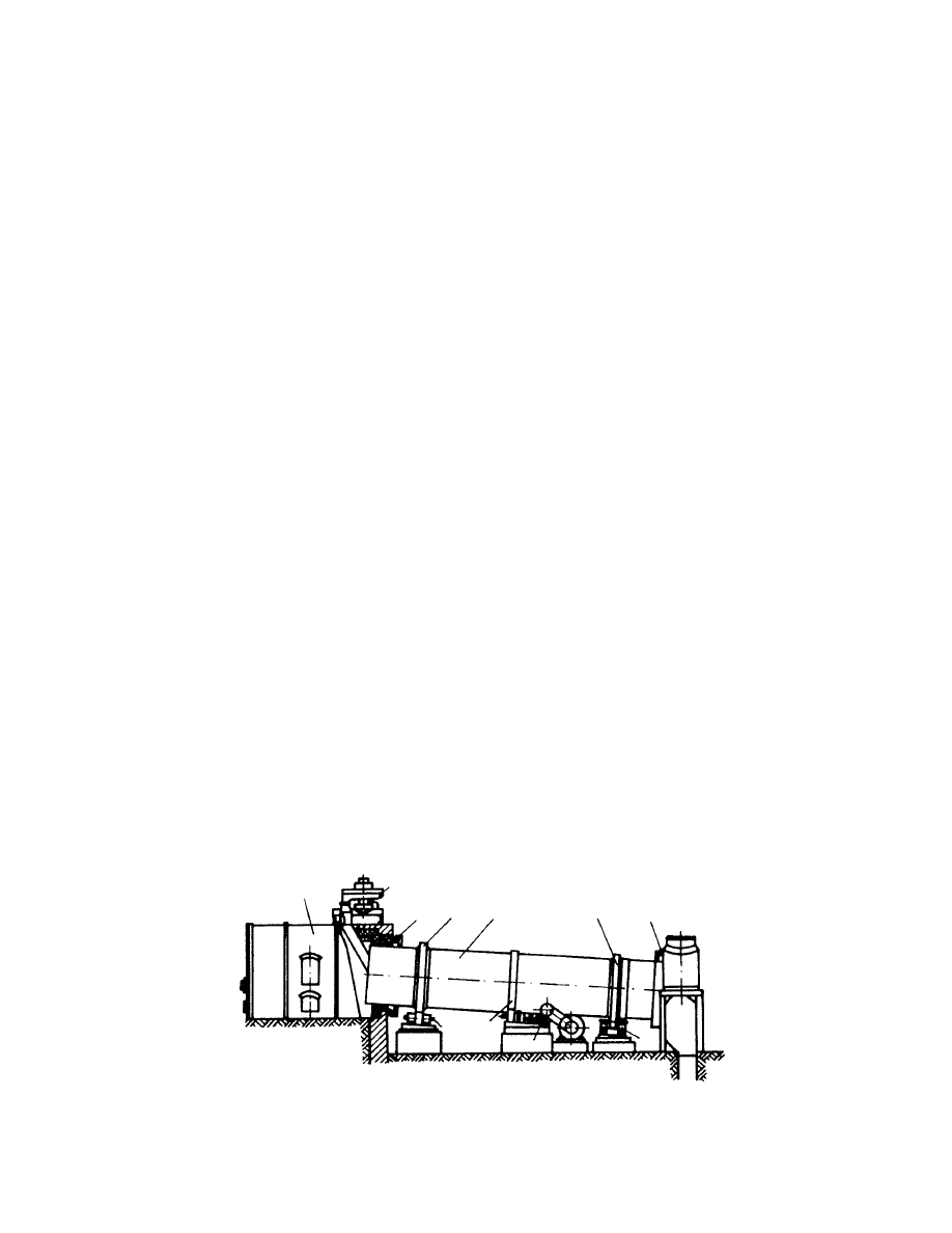
combustion. A typical rotary dryer is shown schemat-
ically in Figure 43.1. The main component of this
dryer is the steel shell (3) lined with a refractory lining
and set up on rollers (7) by means of bandages
(hoops, 10) located on the shell. The shell is rotated
typically using a toothed gear (5). The shell is set up
obliquely with a slope of 2 to 58 to the horizontal.
Inside the shell, there are lifters fastened to the inner
surface of the drum. During operation, these lifters
lift the coal granules and shower them gradually in-
side the shell in the stream of the flowing heating gas.
Various lifter s are shown in
.
1
2
9
10
3
10
9
8
5
6
7
4
FIGURE 43.1 Schematic of a rotary dryer.
ß
2006 by Taylor & Francis Group, LLC.
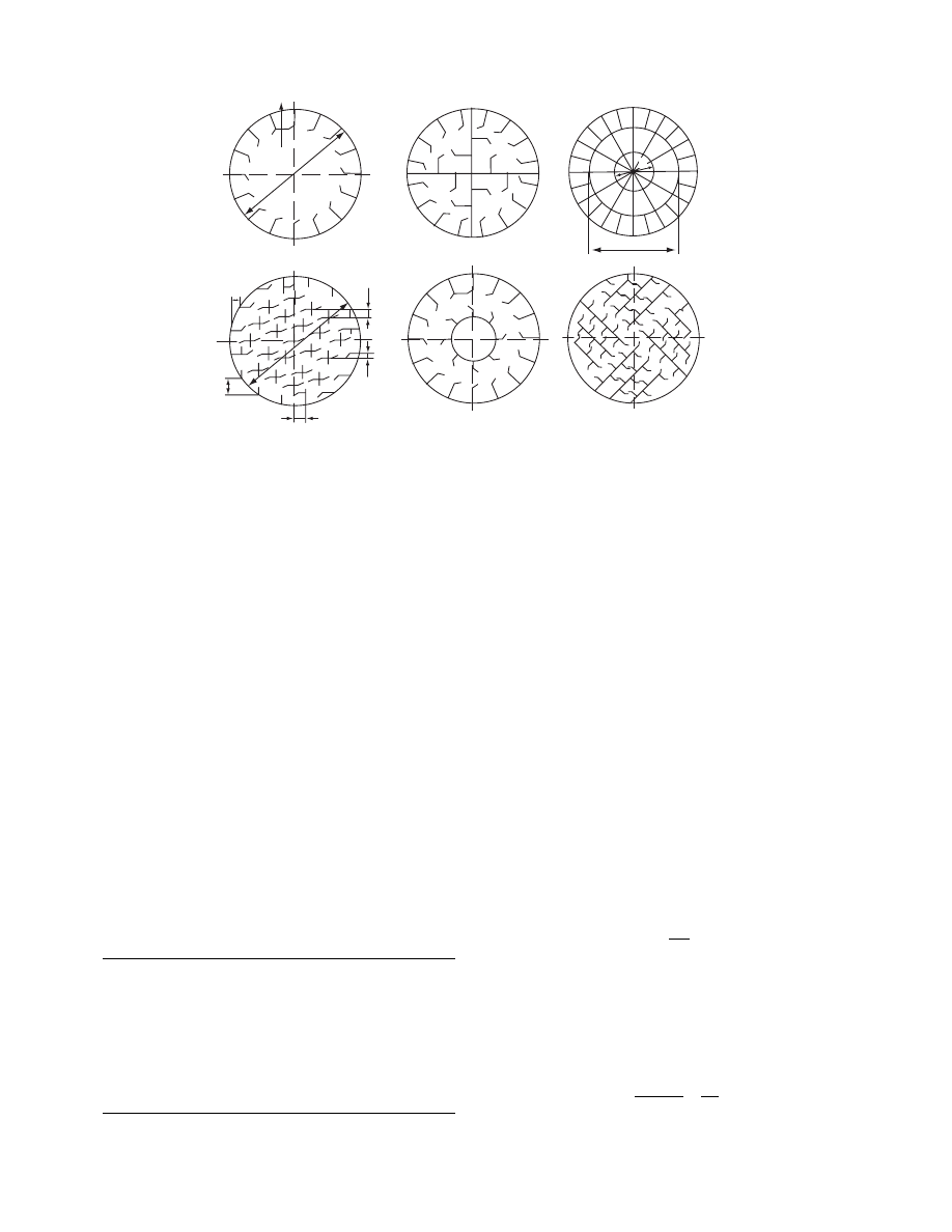
For drying of big lumps of coal that stick to the
shell wal l, type a devices may be used . For lumpy
coals of low friab ility, type b devices may be us ed.
For fine r coal granule s of high fria bility, the lifting–
mixing devices are made in the form of separat e cell s
(type f ). For superfine coals (dust ), a system of c losed
cells (type c ) is used. The en ds of the dryer shell are
sealed labyri nthinel y to the inlet and outlet head s.
The co mbustion g ases leavi ng the dryer carry co al
dust, whi ch may be up to 15% of the co al fed to the
dryer. Hence the dryer exhaust is direct ed to cyclon es
or elect rostatic precipi tators to separat e the entrained
dust. The final loss of coal doe s not exce ed 0.5 to
1.5%, de pending on the type of equipment used for
cleanin g the combu stion ga ses. Typica l rotar y dru m
dryers for coal drying are in the follo wing sizes:
(a) Shell diame ter, 1.5 to 3.5 m
(b) She ll length, 12 to 30 m or mo re
The drive mo tor power requir ed depend s on the
dryer diame ter, its lengt h and rotat ing speed, and
holdup weight, and is as follows:
D (m)
L (m)
Motor Power (kW)
1.5
8
8
1.8
12
14
2.2
12–14
17–20
2.8
12–14
28–35
3.2
18
75
3.5
27
120
Typical operating parameters for rotary dryers
used for coa l drying are given in
.
The heat consumption in such dryers amounts to
about 3700 kJ/kg H
2
O. The drying time is about 15 to 40
min at a holdup fraction of 0.15 to 0.25. The gas velocity
at the dryer outlet should not be more than 2 to 3 m/s for
the drying of fine coals derived from washing and not
more than 0.5 to 1 m/s for the postflotation concentrates
to avoid excessive carryover of coal. The dimensions of
the rotary dryer are determined based on the drying rate
per unit volume, which is given in Table 43.1.
Generally, one cannot know the suitable drying
rate per unit volume because it varies with the dryer
diameter, the flow rate, the temperature of the drying
medium, and the rotation speed of the shell. One has
to calculate dryer volume based on the heat transfer
coefficient.
Knowing the drying rate per unit volume
(amount—kilograms—of moisture evaporated in
time unit from 1 m
3
of shell volume), one can calculate
the volume of dryer shell V
b
from the formula
V
b
¼
W
N
V
(43:1)
From the volumetric flow rate of the drying medium
V
g
, assumed fractional holdup b (0.05 to 0.3), and the
velocity of drying medium in the drum u, one can
calculate the diameter of the dryer as
D
¼
1:13
ffiffiffiffiffiffiffiffiffiffiffiffi
1
b
p
ffiffiffiffiffiffi
_
V
V
g
u
s
(43:2)
0
d
1
d
2
d
2
= 0.45D
d
1
= 0.22D
z = 24
a = 0.4D
b = 0.10
c = 0.06D
L
1
= 0.15
D
L
2
= 0.1
D
a
L
1
L
2
c
b
D
(d)
(e)
(f)
(a)
(b)
(c)
L = 0.11D
z = 16
z = Number of plates
FIGURE 43.2 Scheme of the lifting–mixing devices for rotary dryers.
ß
2006 by Taylor & Francis Group, LLC.

The length of the dryer is calcul ated from the form ula
L
¼
V
b
0:785D
2
(43 : 3)
The length –diam eter ratio L /D is us ually in the range
of 5 to 10. The speed of rotat ion of the shell n depend s
on the lengt h L, diame ter D , angle of incli nation of
shell a, and the drying time t. It is determined by the
empirical formula
n
¼
k
1
k
2
L
Dtg a
(43 : 4)
where k
1
¼ coeffici ent charact erizing the motion of
material in the drum. For co current dryers used for
coal drying, k
1
¼ 0.2 to 0.7; k
2
¼ coeffici ent taking
into accou nt the type of distribut ing or mixing device.
For lifting devices, k
2
¼ 0.5; for the cell and section al
devices , k
2
¼ 1.0
In practi ce, the peripher al speed of rotation is
usually 15 to 25 m/min. The dwelli ng tim e of coal in
the dryer t is very impor tant in the drying of coking
coals. Excessi ve dr ying time can worsen the agglom -
erating pro perty of the coal. The drying tim e of co al
can be determined from the form ula
¼
2z
u
b
N
v
X
1
X
2
2
(X
1
X
2
)
(43 : 5)
43.2.2 R
OTARY
-T
UBE
D
RYER
The rotar y-tube dryers are used widely for coal dry ing
in brown co al briquetting plants . They are also used
for drying of hard co als. Thes e dryers are indire ct
dryers he ated by satur ated steam at pressur es of
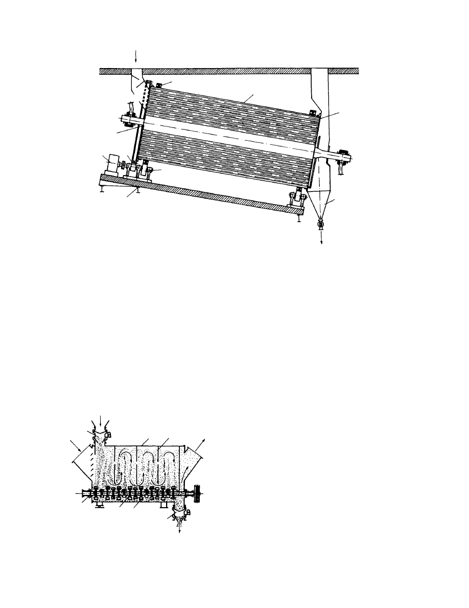
0.15 to 0.55 MPa . This dryer (
) consis ts
of a slopin g drum (1), in which the pe rforated walls
have seaml ess tubes fasten ed to them (2) at diame ters
of about 102 to 108 mm. The dryer shell roll s
on specia l rings (6) an d rollers (7) and is driven
by power trans mitted (8) by mean s of a gear wheel
(9). The heatin g steam enters the drum throu gh the
pin (3). The mois t coal is fed insid e the heati ng tubes.
As a consequen ce of the slope and rotation, the co al
is displaced gradual ly toward the heati ng tubes
from the inlet to the outlet. In the he ating tubes are
install ed screw guides, which con trol the displ acement
of co al. The varia ble-pitch guides install ed in tube s
prevent the displ acement of co al in tubes very fast .
The dr ied coal is co llected in the low er part of the
chamber (5). The steam c ondensate is drained
through a pin placed in the low er en d of the drum.
In this type of dryer, the convecti ve he at trans fer
coeffici ent from steam to coal is about 25 W/m
2
K.
Some techn ical da ta for the drum- tube dryers are
as foll ows:
.
Diameter D
¼ 2500, 2800, 3130, 3350, 3750, and
4000 mm
.
Drum lengt h L
¼ 7 to 8 m
.
Angle of inclinati on of dr um a
ffi 88
.
Speed of rotation n
¼ 5 to 9 rpm
.
Drying rate per unit expo sed su rface N
F
¼ 5.4 to
8 kg/m
2
h
.
Temperat ure of vap or, 90 8 C
.
Coal tempe rature at outlet, 80 8 C
.
Heat con sumption , 2950 to 310 0 kJ/kg H
2
O
.
Dust co ntent in va por in drying of brown coal,
~25 g/m
3
In brown coal briquet ting plants , these dry ers are
heated by exhau st steam from the briquet ting ma-
chines. The steam carrie s away oil drop lets, which are
carbonized, forming deposits on the tube walls. To
remove impurities from the dryer tubes, these tubes
may be washed by circulation of trichloroethylene at
TABLE 43.1
Operating Parameters for Rotary Dryers Used for Coal Drying
Coal Type
Coal Moisture
(%)
Heating Medium
Temperature (
˚
C)
System of
Mixing Devices
Drying Rate per Unit Volume,
N
v
(kg/m
3
h)
Before
Dryer
After
Dryer
Before
Dryer
After
Dryer
Hard coal
9
0.6
900
60
Figure 43.2, type a
35–40
Fine coal mixed with
postflotation concentrate
17
5
740
110
Figure 43.2, types a, b
93
Postflotation concentrate
22
5
770
105
Figure 43.2, types a, b
116
High-ash mud, grain
size 0–2 mm
30
1
750
120
Figure 43.2,
types b, d, e, f
120
ß
2006 by Taylor & Francis Group, LLC.
70 to 808C for about 3 h. The spent trichloroethylene is
distilled for reuse.
43.2.3 C
HAMBER
D
RYER
E
QUIPPED WITH
S
TIRRERS
Chamber dryers equipped with stirrers are commonly
used for drying of flotation concentrates (Figure
43.4). The dryer operates in a cocurrent mode. Hot
combustion gases supplied to the dryer by a duct (5)
meet at the outlet the cold and moist coal supplied by
another duct (7). The dryer consists of a chamber (1)
fitted with baffles (9) and two shafts (2) rotating in
opposite directions on which paddles are mounted
(3,4). The moist coal supplied by a duct (7) is lifted
and thrown by stirrers (3,4) from the inlet to the
outlet (8). The stirrer paddles (3,4) are also useful
for breaking sintered coal. Some technical data are
as follows:
.
Combustion gas temperature at inlet, 7008C
.
Combustion gas temperature at outlet, 1108C
.
Chamber width, 2000 to 2400 mm
.
Chamber length, 2000 to 3400 mm
.
Drying rate per unit volume, N
v
¼ 600 to 750 kg
H
2
O/m
3
h
.
Coal moisture content at inlet, 18 to 22%
.
Coal moisture content at outlet, 8.5%
.
Heat consumption, ~3150 kJ/kg H
2
O
.
Speed of rotation of shaft, 7 to 10 rpm
For pasty feeds, which tend to cake during drying,
chains are fastened to the paddles to break the cakes
formed during drying.
43.2.4 P
NEUMATIC
D
RYERS
Pneumatic dryers are widely used for drying coal and
flotation concentrates. The basic element of the dryer
is a vertical tube of diameter 650 to 1100 mm and
length 14 to 35 m through which the hot drying
medium (e.g., combustion gases or air) flows from
bottom to the top. The coal being dried is lifted by
the stream of drying gases and transported from
Inlet of coal
Outlet of vapors
6
1
Inlet of steam
3
8
9
7
4
Outlet of coal
5
Outlet of
condensate
2
FIGURE 43.3 Drum-tube dryer.
7
5
1
9
2
3
4
8
6
FIGURE 43.4 Chamber dryer equipped with stirrers.
ß
2006 by Taylor & Francis Group, LLC.
bottom to top. Duri ng pneumat ic transpo rt, the co al
grains are heated a nd dried. Thus , the drying gas
velocity dep ends on the grain size of coal being
dried; in practi ce this amoun ts to 10 to 40 m/s . In a
commer cial dryer, the disi ntegra tor con nected to the
vertical drying tube at the bot tom is installed , which
serves to cru sh and dry mois t lump coal from the
feedin g chute. Dryi ng hot gas enters the disi ntegra tor
and meet s the moist coal. The mois t coal is highly
disturb ed and mixed with hot gas, and drying is
strong ly ac celerated. Genera lly, abo ut 5 0% of the
water to be dried is remove d from the coal in the
disintegra tor. The most intens ive drying oc curs in
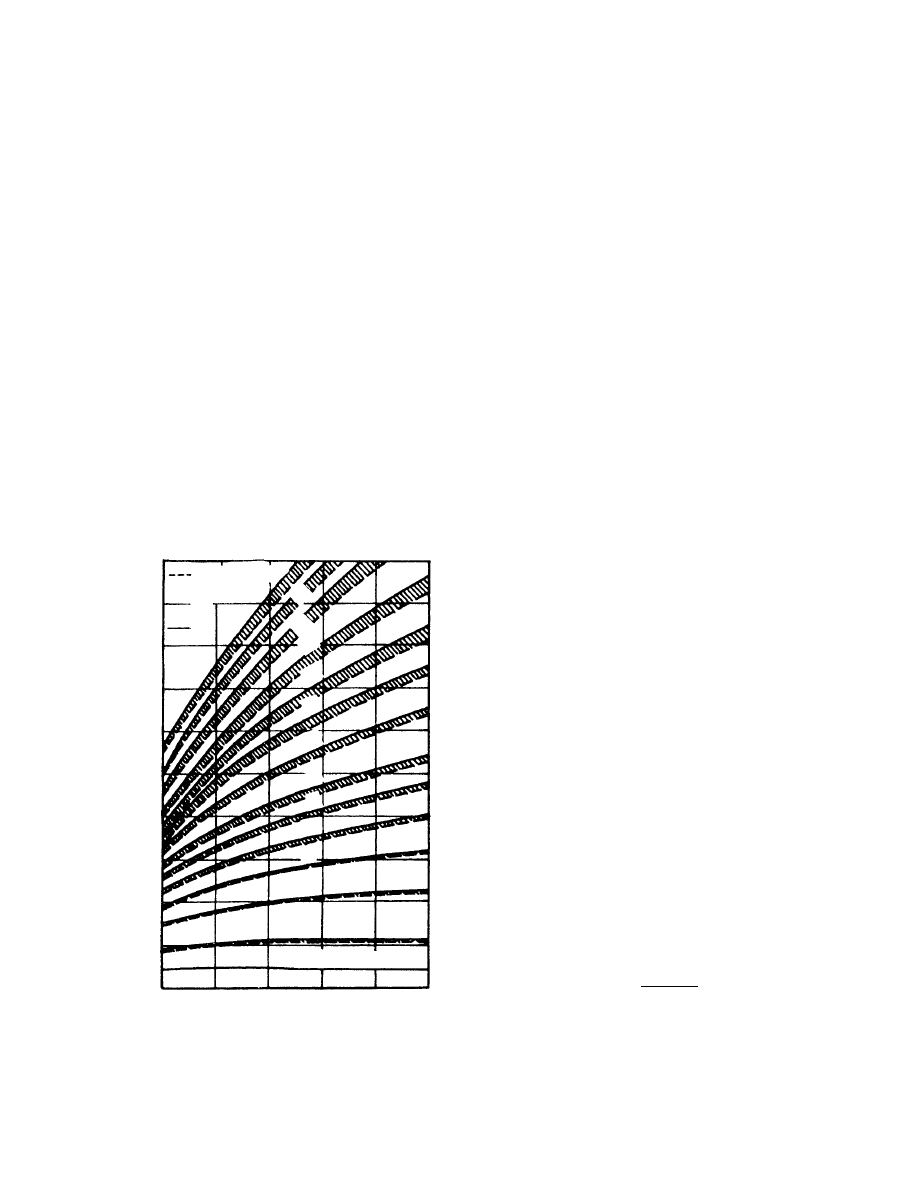
the first 2 to 3 m of the dryer. The drying pro cess is
conditi oned by the heati ng medium veloci ty in rela-
tion to the grain size of coal. This velocity increa ses
with grain size, as shown in Figu re 43.5. Thi s is ve ry
impor tant becau se co arser grains reside a longer time
in the he ating medium . The large surface of contact of
the grains with the heatin g medium allows rapid dry-
ing, whi ch for finely ground c oals is of the or der of a
few seco nds. The short drying time relate s only to the
first drying period, i.e., to the evaporat ion of surface
moisture. The heating medium pa rameters ha ve a
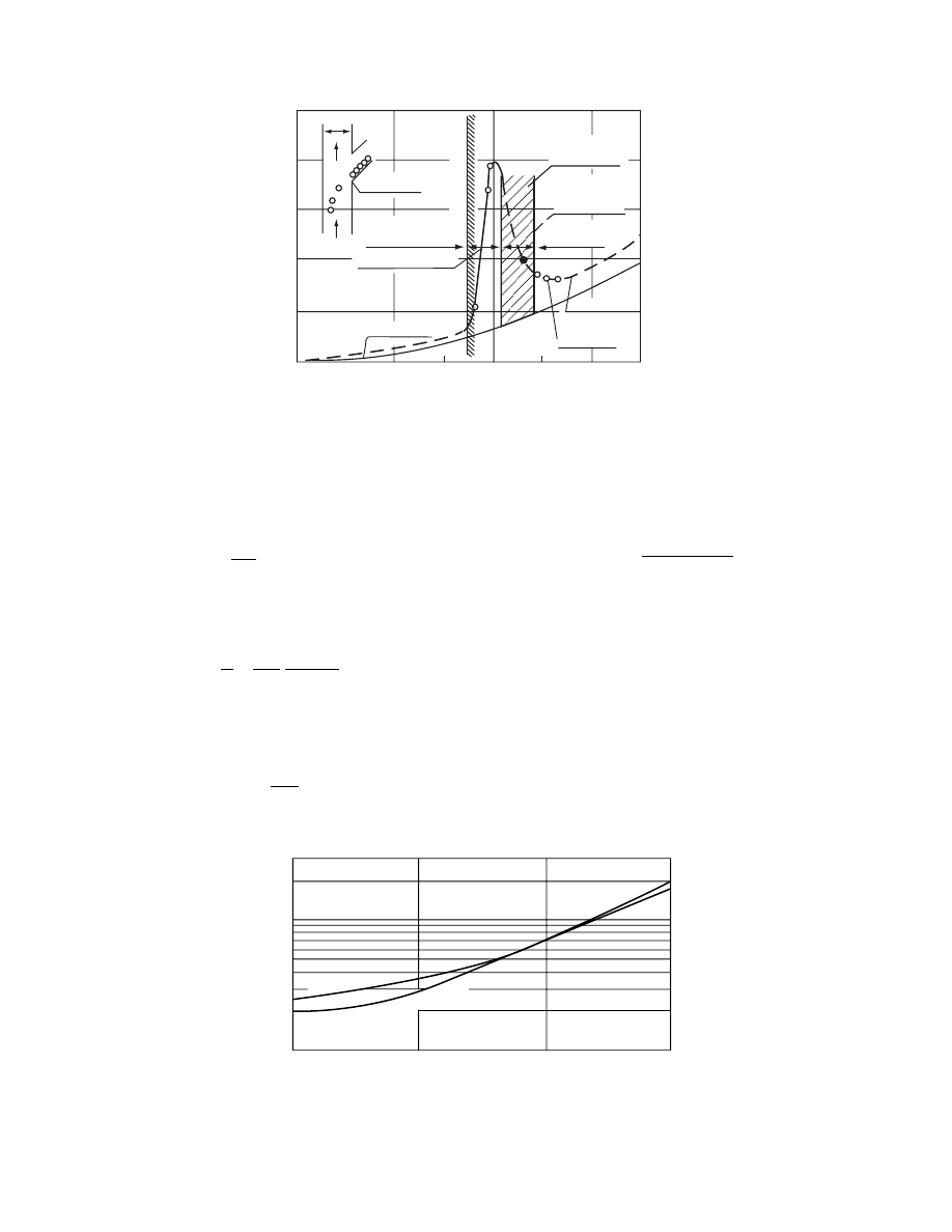
decisive effect on this period. The pressure drop char-
acterist ics of a pneumat ic dryer are illu strated in
, given by Barth. In the vertical tube, the air
flows upwar d. Into the a irstream is supplied a graine d
material shaped as globule s. At low air veloci ties the
globule s fall down ward; at a high veloci ty they are
entrained by the airs tream. The pressur e drop is in-
crease d rap idly at the moment when the globule s are
entrained be cause the mate rial begins to colle ct in the
tube. Bey ond the c ritical zone charact erized by a
rapid dro p of pressur e is the operation zo ne of pne u-
matic dry ers. To selec t the optim um flow velocity, one
must a void operatio n at the cloggin g zone. The clog-
ging z one is idios yncrat ic to each dryer. Here, a slig ht
increa se in solid loading or slight fall in pressur e drop
causes the cloggi ng of the pipe. The cloggi ng zone
separates the critical trans ition zone from the zone
of pneu matic trans port. Altho ugh Figu re 43.6 doe s
not refer to coal trans port, be havior is sim ilar when
transp orting groun d coals. In pne umatic trans port,
heat and mass exchange take place mostly by con vec-
tion. The heat exchange between the drying med ium
and the co al pa rticles suspended in this medium can
be defined by the Fro¨ sslin g form ula
Nu
¼ 2 þ 0:55Pr
1=3
Re
1=2
(43:6)
In the first 2 to 3 m of drying tube, heat transfer to the
coal particles takes place promptly, so the heat trans-
fer coefficient in this zone is defined as
Nu
max
¼ 0:95 10
4
Re
2:15
,
400 < Re < 1300
Nu
max
¼ 0:76Re
0:65
30 < Re < 400
shows the relationshi p betwee n the Nus-
selt number and the Reynolds number for heat trans-
fer between particles transported by the air at 0 to
1008C.
The heat supplied to the coal particle suspended in
the gas stream is
_
Q
Q
¼ h
c
pd
2
p
Q
m
(43:7)
The mean temperature difference Q
m
is calculated as
the logarithmic mean
Q
m
¼
Q
1
Q
2
ln Q
1
=Q
2
where
Q
1
¼ T
1
T
m1
and
Q
2
¼ T
2
T
m2
50
45
40
35
30
25
20
15
10
5
0
200
400
600
800
1000
Combustion
gases from
coke oven
gas
Air
30
25
20
15
12
8
6
5
4
3
2
1
d = 0.5 mm
Drift velocity (m/s)
Temperature (
⬚C)
FIGURE 43.5 Drift velocity of coal grains according to
Rammler and Augustin.
ß
2006 by Taylor & Francis Group, LLC.
The quantity of heat necessary to evaporate the sur-
face moisture is
Q
¼
pd
3
p
6
z
s
(X
1
X
2
)DH
(43:8)
The time of the drying process is estimated from the
formula
¼
Q
_
Q
Q
¼
d
p
z
s
6h
c
X
1
X
2
Q
m
DH
(43:9)
At low Reynolds numbers (Re
ffi 0) the Fro¨ssling
formula gives
Nu
¼
h
c
d
p
l
ffi 2
After substitution of this value in Equation 43.9, the
drying time is given by
¼ DH
d
2
p
z
s
(X
1
X
2
)
12Q
m
l
(43:10)
In practice, the moist coal particle diameter is larger
than the dried, and the particle diameter continues to
change with the moisture decrease, so the correction
for the drying time based on the coal particle diameter
must be taken into account. The length of the drying
duct, i.e., the effective length of the drying tube, is
then
L
0
¼ u
(43:11)
The velocity u is the mean velocity with which the coal
grain flows in time t through the lifting tube.
Ø 100
1250
1000
750
500
250
1000
750
500
250
0
0
5
10
15
Velocity
u (m/s)
Pressure drop
Δp
(Pa)
20
25
30
35
Loss of energy (pressure)
T
/m
3
(Pa)
Without material
With material
Pneumatic
transport
Critical
transition
zone
Plugging limit
Upper limit of velocity
Economical
transport
Fluidized layer
Particles are
falling down
m = 0.42 kg/s
FIGURE 43.6 Pressure drop of drying medium in empty tube as well as during transport of material (type of material:
spheres, 7.5 mm diameter).
Johnstone
, Pigf
ord,
Cha
pin
Frössling
1
1
2
3
4
6
8
10
20
30
10
100
1000
Nu
Re
FIGURE 43.7 Heat reception by globules in air at temperatures of 0 to 1008C.
ß
2006 by Taylor & Francis Group, LLC.

u
¼ u
g
u
0
(43 : 12)
The veloci ty of the dr ying medium is taken as
u
g
¼ (1 : 1 1:25)u
0
(43 : 13)
The sedim entation veloci ty can be defined on the
basis of the Archi medes number.
Ar
¼
gd
3
p
u
2
g
z
s
z
g
z
g
(43 : 14)
Know ing the Archimed es numb er, one can calcul ate
the Reyno lds numb er; for Ar < 84,000 ,
Re
¼
Ar
13 : 9
1 =1 :4
(43 : 15)
For Ar > 84,000
Re
¼ 1: 71
ffiffiffiffiffiffi
Ar
p
(43 : 16)
From the Reynol ds number we estimate the theoret -
ical sedim entation veloci ty of the co al parti cle as
u
0
¼
Rev
g
d
p
(43 : 17)
The tube length calcula ted based on formula [11] is
too small since with coarse grains (0.2 to 1.0 mm) this
does not take into account the star ting length ov er
which the grains reach their terminal ve locity. For the
correct ion of this star ting (tran sient) length we sug-
gest the formu la
L
00
¼ k
L
u
g
d
p
(43 : 18)
where k
L
¼ 10
3
s/m . The total length of the lifting tube
will be
L
T
¼ L
0
þ L
00
(43 : 19)
The qua ntity of drying medium requir ed depends on
the heat needed for the drying acco rding to the he at
balance equati on
_
G
GC
p
(T
1
T
2
)
¼ _L
L
0
(C
s
þ Cw
1
)(T
w
T
m1
)
þ _L
L
0
(w
1
w
2
)DH
þ L
0
(C
s
þ Cw
2
)(T
m2
T
w
) (43 : 20)
where _
L
L
0
¼ dry soli d flow rate (kg/ s), C
s
¼ specific
heat of solid (kcal /kg
K), W ¼ dr y basis mois ture co n-
tent, T
w
¼ wet bulb tempe ratur e ( 8 C), an d T
m
¼ solid
tempe rature ( 8 C).
In indu strial practi ce, the lengt h of the lifting tube
is determ ined most frequen tly based on the drying
rate per unit vo lume, which is a s follo ws:
N
v
¼ 400 600 kg H
2
O =m
3
h for ground coal
N
v
¼ 700
900 kg H
2
O =m
3
h for postf lotation
co ncentra te
N
v
varies general ly with hot gas tempe ratur e, solid–
gas rati o, and gas veloci ty. Therefor e, suit able drying
tube volume must be calculated on the ba sis of the
equati on of heat transfer an d he at balance. N
v
gives
the approxim ate va lue of the drying tube volume . The
drying rate per unit volume is defi ned by
N
v
¼
_
W
W
V
p
(43 : 21)
The diame ter of the liftin g tube is calcul ated from the
formu la
D
¼
ffiffiffiffiffiffiffiffiffiffiffiffiffiffiffiffi
_
V
V
g
0:785u
g
s
(43 : 22)
The volume tric gas rate of the drying medium can be
calculated based on the heat balance Equation 43.20:
_
V
V
g
¼
_
G
G
z
g
(43 : 23)
From Equat ion 43.21, the volume of the lifti ng tube
V
p
can be calculated. Know ing the liftin g tube vol-
ume V
p
and its diame ter, we c an calculate the length
of the lifting tube as
L
e
¼
4V
p
pD
2
(43:24)
In general, the lengths of lifting tubes do not exceed
35 m. The coal feed to the lifting tube is situated 4 to
6 m above the gas feed. The dryer capacity depends
on the diameter of lifting tube.
Diameter (mm)
700
830
900
1100
Capacity (Mg/h)
20–35
30–55
40–65
50–75
The heating medium temperature at the dryer inlet
is 550 to 7008C and 70 to 1708C at the dryer outlet.
The initial moisture of coal is usually 10 to 15%; the
final moisture is about 4 to 6%. A typical pneumatic
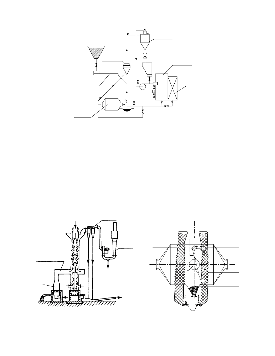
dryer setup for coal drying is shown in
.
Wet coal from the bin (11) is proportioned by feeder
ß
2006 by Taylor & Francis Group, LLC.
(12) to the lifting tube (5), where it is carried away by
the combustion gas stream derived from fuel combus-
tion in the furnace (2). Drying occurs in the tube, after
which the coal is separated from combustion gases in
the cyclone (6) and then in a bank of cyclones (7).
Negative pressure in the system is generated by a fan
(8). The dried and separated coal is directed to the
conveyor (10) through the shutter closures (15,16),
which are the lower seals of the cyclones (6 and 7).
The heavier coal particles, which fall down in the
lifting tube (5), are directed to the dried coal conveyor
(10) through the screw (9). The system is equipped
with explosion flaps (17).
The Parry-type dryer for coal drying is shown in
Figure 43.9. Here, wet coal is proportioned into the
drying chamber (2) by means of a feeder. Around
the drying chamber are installed cyclones to separate
the coal from combustion gases. The combustion
gases necessary for drying are generated in the cham-
ber (1) by combustion of a solid or liquid fuel. The air
for combustion is supplied by the fan (6). Another fan
(5) allows recycling of a part of the combustion gases
to the drying process. The capacity for this type of
dryer generally exceeds 50 Mg/h at initial and final
coal moisture levels of 35 and 4%, respectively.
The dimensions of a typical dryer of this type are
as follows:
.
Diameter
¼ 2.7 m
.
Height
¼ 6 m
.
Diameter of furnace chamber
¼ 4.2 m
.
Height of furnace chamber
¼ 10 m
.
Thermal power of chamber
¼ 13.4 MW
The combustion process is controlled automatically;
the temperature of the combustion gases outflowing
to the environment is the signal for control.
43.2.5 F
LUID
-B
ED
D
RYERS
Fluid-bed dryers are widely applicable for coal owing
to the high intensity of this drying process. Intense
drying is achieved as a result of good mixing, use of a
high-temperature heating (and fluidizing) medium,
10
16
18
15
6
17
11
12
13
7
8
4
4
14
3
2
1
5
17
9
FIGURE 43.8 Schematic of pneumatic dryer for coal drying.
Outlet
Fuel
Circulating
gases
Wet
coal
2
3
Air
5
6
1
FIGURE 43.9 Schematic of Parry-type dryer for coal drying.
ß
2006 by Taylor & Francis Group, LLC.
and ease of control . A fluidized stat e is achieve d when
gas with a pro per velocity passes throu gh the co al
layer. The gas flow velocity at which the pa cked bed
is con verted into a fluidized bed is know n as the
minimum fluid ization veloci ty. One feature of the
fluidized bed is its high porosit y, defi ned by
c
¼
V
0
p
V
z
¼ 1
V
m
V
z
(43 : 25)
where V
p
0
¼ volume of solid-free space, V
z
¼ total vol-
ume of bed, and V
m
¼ volume of soli d material in the
bed (
¼ L/ z
s
).
A packed be d of coal has a por osity in the range
of 0.4 to 0.5. The poro sity of a fluidized bed can v ary
over a wi de range, dep ending on the gas flow veloci ty
(c
¼ 0.4 to 1). The mini mum veloci ty of fluidiza tion
for the co al and other fri able materials for which the
porosit y c
0
¼ 0.4 can be calcul ated from the form ula
Re
cr
¼
Ar
1400
þ 5: 22
ffiffiffiffiffiffi
Ar
p (43 : 26)
For c
0
¼ 0.48
Re
cr
¼
Ar
710
þ 4
ffiffiffiffiffiffi
Ar
p (43 : 27)
From the crit ical Reynol ds numb er Re
cr
, one can
calcula te minimum (critical) veloci ty of fluid ization as
u
cr
¼
Re
cr
u
g
d
p
(43 : 28)
Equation 43.26 and Equat ion 43.27 are sh own grap h-
ically in Figure 43.10. For bed s of coal, the pr essure
drop can be estimat ed from the formu la
Dp
¼ H (1 c)(z
s
z
g
)g (43 : 29)
The por osity of the flui dized bed can be estimat ed
using
c
¼
18Re
þ 0: 36Re
2
Ar
0 :21
(43 : 30)
The height of the fluidized bed is readil y given by
H
¼ H
0
1
c
0
1
c
(43 : 31)
For coal drye rs, a space of a bout 3.5 to 4.5 times the
fluid-bed he ight should be allowed as the disenga ge-
ment he ight h
1
:
h
1
¼ 3: 5H 4: 5H (43 : 32)
The con vective heat trans fer co efficien t betwee n ga s
and solid in the fluidized bed can be estimat ed from
the co rrelatio n
Nu
¼ 10
2
Re
c
Pr
1 =3
(43 : 33)
Drying kinetics in the fluid ized bed requ ires in add -
ition the fulfillment of the relationship
H
¼
_
G
G
z
s
(1
c)S
(43:34)
The mean residence time t of coal in the fluid-bed
dryer is determined empirically and t can be calcu-
lated by
¼
3600H
0
Az
s
F
where F
¼ coal feed rate (kg/h), A ¼ fluid-bed area
(m
2
), and H
0
¼ static coal bed height (m).
In coal drying, the temperature of drying gases at
the dryer inlet is 300 to 7008C and the temperature of
the fluidized bed is 70 to 808C.
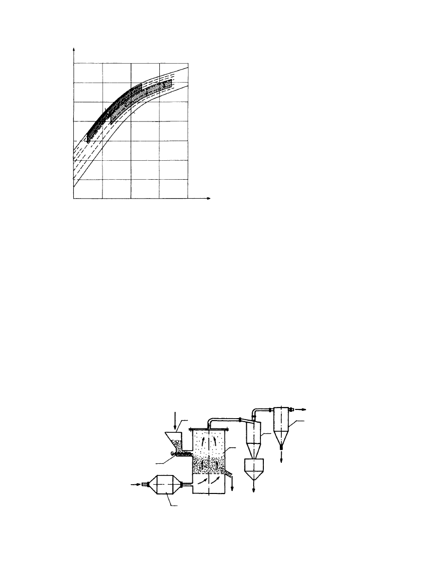
shows the relationshi p betwee n ga s
velocity and particle diameter for various porosities
of bed for coal of density z
¼ 1200 kg/m
3
and for gas
temperature T
¼ 1008C. Between curves 1 and 5 there
is a zone of dryers operating as a loose bed. Industrial
fluid-bed dryers operate in the range of c
¼ 0.55 to
0.75. Zone 2 includes coal particles from 30 to 40 mm
up to 6 to 7 mm. For fountain-type dryers, this zone
can widen (3) up to 25 to 30 mm. The aerofountain-type
dryers (4) operate at bed porosity c
¼ 0.75 to 0.9. In
dryers of this type, one can dry coal-containing particles
from several micrometers to tens of millimeters. Owing
to their simple design and high capacity, fluid-bed
10
–6
10
–2
10
2
10
4
Re
cr
Ar
y
0
= 0.48
y
0
= 0.4
10
–4
10
4
10
6
10
8
10
–2
10
2
1
FIGURE 43.10 Relationship between critical Reynolds
number and Archimedes number.
ß
2006 by Taylor & Francis Group, LLC.
dryers are widely applicable in the industry for coal
drying. One type of fluid-bed dryer commonly used
for coal drying is the Fluo-Solids dryer marketed by
Dorr-Oliver (United States). This dryer operates with a
small coal bed (300 to 400 mm) and has a very high
drying rate per unit exposed surface of 2000 kg H
2
O/
m
2
h. Figure 43.12 schematically shows the Fluo-Solids
dryer with the roller chamber designed by Dorr-Oliver
for coal drying. Moist coal from the bin (1) is propor-
tioned by feeder (2) to the drying chamber (3). Com-
bustion gases from the combustion chamber (4) are
mixed with air to obtain the desired temperature (300
to 7008C). The heat consumption is typically in the
range of 3100 to 4000 kJ/kg H
2
O. The hot gases pass
through a screen and the coal layer, causing fluidization
of coal. The exhaust gases leaving the dryer are cleaned
in a cyclone (5) and cloth filter (6). Some technological
data for typical coal fluid-bed dryers for coal operating
in the United States are given in Table 43.2.
43.2.6 F
LUID
-B
ED
D
RYER WITH
F
OUNTAIN
B
ED
(S
POUTED BED
)
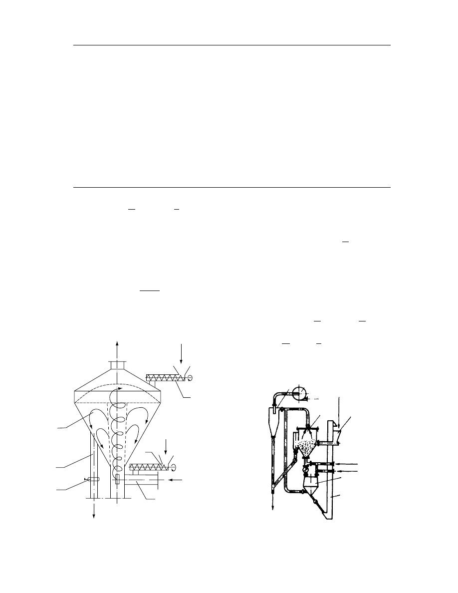
In recent years, fluid-bed dryers wi th a foun tain
(spout ed) bed have be come popul ar for drying of
coal. The fountain bed is ach ieved in a co nical–
cylind rical apparat us (
) . The hot gas
stream supplie d to the dryer by tube (3) carries away
the coal g rains supplied by screw (2) an d moves them
upwar d. The lifted co al grains fall aside and move
downward along the annulus.
sho ws a schema tic of a spou ted bed
dryer for coal as designed by Fiodorov and Michai-
lov. Wet coal is supplied to the conical drying cham-
ber. The gas velocity decreases gradually in the
conical chamber owing to which coarser coal grains
fall downward. The finest grains are entrained by the
gas stream and then separated in the cyclone (3). The
intermediate fractions are circulated in the drying
chamber (1), after which they pass through a vertical
slit in the chamber wall for discharge. Control of the
slit opening allows control over the dryer holdup. The
coarse coal particles fall into the bin (5) from which
they are recycled to the dryer by a bucket elevator (6).
For spouted bed dryers, it is very important to deter-
mine the gas velocity at which the spouting process
begins and ends. The critical velocity for spouting
depends on the bed height and the physical properties
of the coal and gas, as well as on the geometric shape
and dimensions of the dryer. The incipient spouting
velocity can be estimated from the correlation
m
(m/s)
10
2
10
1
10
0
10
−1
10
−2
10
−3
10
−4
10
−4
10
−3
10
−2
10
−1
10
−5
Drift
(y = 1)
Constant bed
(y = 0.4)
y
= 0.4
y
= 1
0.8
0.6
5
1
d
p
(m)
FIGURE 43.11 Relationship between gas velocity and par-
ticle diameter.
Wet coal
Inlet
air
2
1
Outlet air
6
5
3
Dry coal
4
Dry coal
FIGURE 43.12 Schematic of Fluo-Solids-type fluidized bed dryer.
ß
2006 by Taylor & Francis Group, LLC.
Re
cr
¼ 0:364 Re
f
D
d
0
1
0:82
tg
f
2
0:1
(43:35)
where Re
cr
¼ critical Reynolds number at which
spouting starts, D
¼ diameter of upper bed section,
d
0
¼ diameter of lower bed section, and f ¼ apex
angle of cone; generally, f
¼ 16 to 708.
Then
u
cr
¼
Re
cr
u
g
d
p
(43:36)
In polydisperse systems, the maximum particle diam-
eter is taken as the particle diameter in Equation
43.36. For optimum geometry one may use
f
¼ 30 50
and
D
d
0
¼ 2 4
For fine grains (Ar < 10
4
), the bed becomes unstable
and may pulsate with a frequency at a low amplitude.
It is found that the dryer height H and separator
diameter D
s
also affect the minimum spouting vel-
ocity. These effects are included in the correlation
Re
cr
¼ 0:176Re
f
D
d
0
1
0:087
H
d
0
0:6
D
s
d
0
0:94
tg
f
2
0:323
(43:37)
TABLE 43.2
Operating Parameters for Some Typical Fluid-Bed Dryers for Coal Used in Various Parts
of the United States
Parameters
Indiana
West Virginia
Kentucky
Utah
Diameter, m
2.1
4.2
4.2
4.2
Screen area, m
2
3.46
13.9
13.9
13.9
Capacity, Mg/h
100
700
230
800
Drying rate per unit exposed
surface, kg/m
2
h
2900
2500
1800
1800
Coal grain sizes, mm
0–6
0–10
0–15
0–38
Moisture at inlet, %
18–22
14.5
—
—
Moisture at outlet, %
2
4.8
—
—
Gas temperature at inlet, 8C
650
410
—
—
Gas temperature at outlet, 8C
80
70
—
—
Gas
Coarse-grained
coal
Fine-grained coal
or coal mud
Hot gas
Dried
coal
5
4
1
2
3
2
Drying of coal
FIGURE 43.13 Schematic of dryer with spouted bed.
3
2
Wet coal
4
1
Combustion gases
Air
5
6
Dry coal
FIGURE 43.14 Schematic of fluidized system with spouted bed.
ß
2006 by Taylor & Francis Group, LLC.
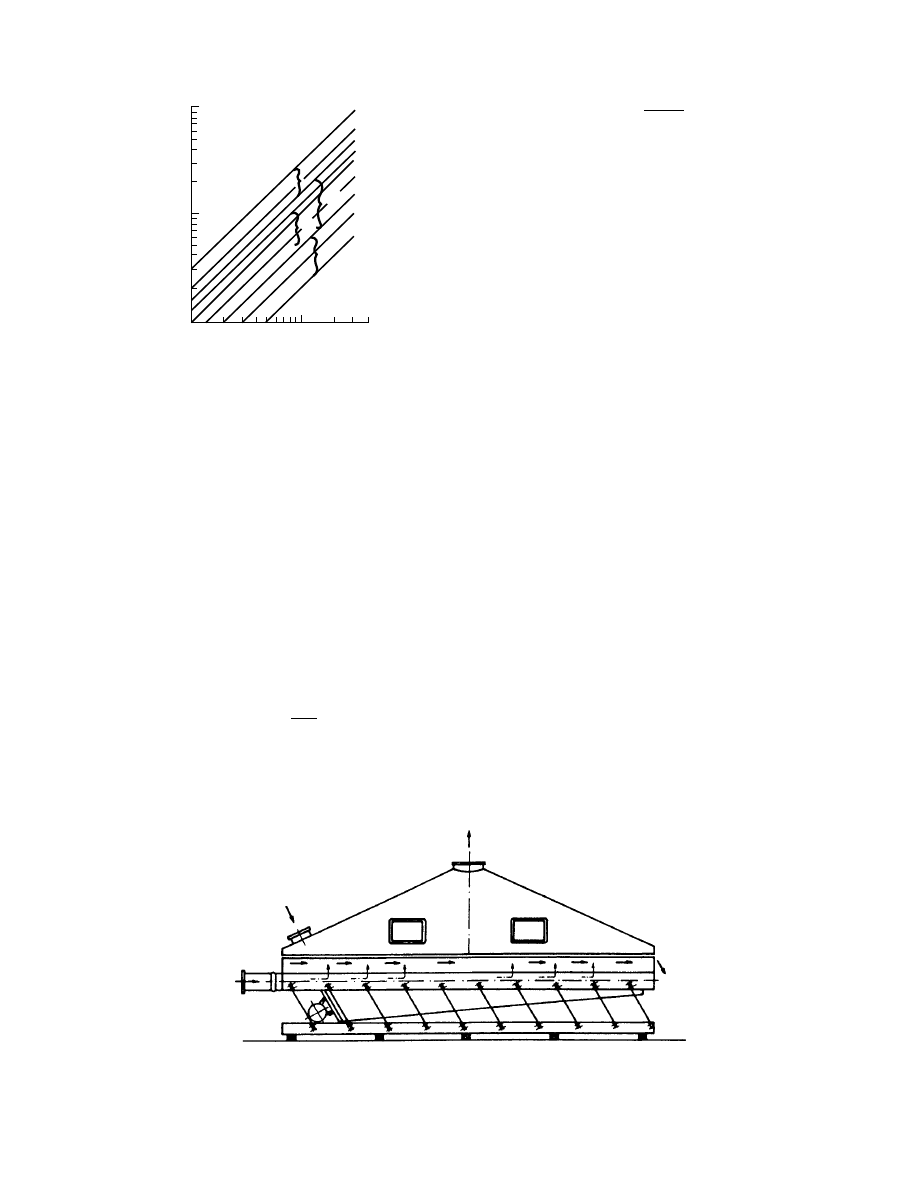
Figure 43.15 presents the relationship between Re
cr
and the Reynolds number for the settling velocity
of grain Re
f
as well as various operating zones of
spouted beds. To estimate the pressure drop across
a spouted bed, one can use the approximate formula
Dp
¼ (0:64 0:75)gz
u
H
0
(43:38)
It is very difficult to calculate the values of convective heat
transfer coefficients for a spouted bed. Uemaki and
Kugo give the following correlation for convective heat
transfer from the gas to the solid particles.
Nu
¼ 5 10
4
Re
1:46
min
u
u
min
1:30
(43:39)
where the Reynolds number is defined by formula
Re
min
¼
u
min
d
p
u
g
where u
¼ flow velocity and u
min
¼ minimum velocity
for spouting.
From Equation 43.39, it appears that the convect-
ive heat transfer coefficients in the spouted bed are in
the range of 3.4 to 17 W/m
2
K; according to other
investigators these coefficients are much higher, say,
up to 51 to 142 W/m
2
K. The drying rates per unit
volume in such dryers are high: N
v
¼ 110 to 290 kg/
m
3
h. For coal drying, the temperature of the drying
medium (e.g., combustion gases or air) is usually not
more than 2008C, unlike the case of conventional
fluid-bed dryers, which operate with much higher
inlet temperatures.
43.2.7 V
IBRATORY
D
RYERS
A vibratory dryer designed by Escher-Wyss is
sketched in Figure 43.16. Vibratory dryers are used
for drying hard and brown coals, especially if it is
necessary to combine coal transport or proportioning
operations with the drying operation. Drying is ac-
complished by hot air or combustion gases passing
through the vibrating coal layer. The coal to be dried
is led into the perforated trough oscillated by an
electromagnetic oscillator. The trough is inclined to
the horizontal at an angle of about 1 to 58. Owing to
the slope of the trough the coal is conveyed with a
velocity dependent on the slope of the trough and on
the vibration amplitude and frequency. For an elec-
tromagnetic vibrator at frequency f
¼ 50 and 100 Hz
and amplitude x
¼ 0.05 to 3 mm, the conveying vel-
ocity of coal is 0.01 to 0.3 m/s. This type of unit can
also be used to cool coal. In vibratory dryers, the heat
requirement is much lower as a consequence of better
utilization of the drying medium.
I
II
IV
III
V
VI
10
4
10
3
10
2
10
3
–10
3
4
Re
cr
Re
f
FIGURE 43.15 Relationship between critical Reynolds
number at incipient spouting and Reynolds number calcu-
lated for sedimentation velocity Re
f
.
Outlet air
Moist air
Hot air
Dry coal
FIGURE 43.16 Schematic of Escher-Wyss-type vibratory dryer.
ß
2006 by Taylor & Francis Group, LLC.
The capacity of vibratory dryers depends on the
trough width B, coal layer height h
0
, and coal drift
velocity u. It can be calculated using the formula
_
L
L
¼ Bh
0
uz
u
(43:40)
The coal layer in the trough is typically
h
0
¼ 2030 mm,
for ground coal
h
0
¼ 4060 mm,
for coal in lump form
For vibratory dryers, the length of troughs does not
usually exceed 10 m. In case the drive is located in the
center of the trough, the trough length can be as high
as 30 m. For long troughs, difficulties are encountered
with proper distribution of the heating medium.
Sometimes the electromagnetic oscillator is replaced
by a power drive in the form of rotating disks that
push the trough that is mounted elastically. Some
technoeconomic data for coal drying in vibratory
dryers are given in Table 43.3.
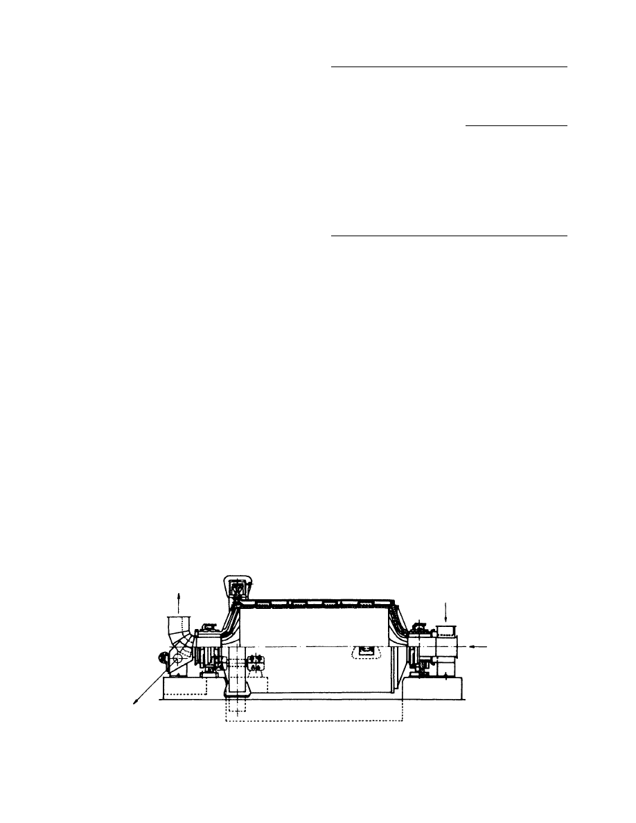
43.2.8 M
ILL
-T
YPE
D
RYERS
Mill-type dryers are used for coal only when it is
advisable to combine grinding and drying operations.
For satisfactory grinding performance, a low mois-
ture level must be achieved. The mill-type dryers are
used generally in power plants using steam boilers
fired by pulverized coal. Figure 43.17 shows a mill-
type dryer, which is really a ball mill in which the coal
is broken and partly ground by the balls. The dryer
consists of a horizontal drum with cones fitted on
both ends. From inside the drum is lined with the
protective lining of basalt, cast iron, carbon, or man-
ganese cast steel (14% Mn).
The drum is filled with balls (diameter, 30 to 80
mm). The filling ratio of the drum is typically 14 to
30%. The filling ratio of the mill has a decisive effect
on the quality and capacity of coal grinding. The balls
are made of manganese or carbon steel toughened to
obtain high hardness and durability. The ball con-
sumption is 80 to 100 g/Mg for soft coals, and it can
reach up to 800 g/Mg for hard coals. The drums are of
2 to 3 m diameter and 3 to 5 m long. The speed of
rotation of the drum is 16 to 30 rpm. For grinding, the
electricity consumption varies over a wide range, from
7 kWh/Mg for short brown coals up to 30 kWh/Mg for
anthracite. Coal grinding in mill-type dryers requires
additional electrical energy (5 to 10 kWh/Mg), which is
consumed by the fan. Coal is fed into the mill through
one of the pins; the heating medium in the form of hot
air or combustion gases is also supplied through the
same pin. The rotary motion of the drum causes the
movement of balls near the drum wall up to about
three quarters of drum diameter as the falling down
of balls under gravity. The falling balls break and
partly grind the coal. The hot air or combustion
gases supplied to the drum simultaneously heat the
balls and coal as well as dry the coal.
The quantity of heating medium used in ty-
pical commercial units is 1.3 kg/kg for brown coals
and 2.0 kg/kg for anthracite. The heating medium
temperatures depend on the moisture of the coal. Fig-
TABLE 43.3
Technoeconomic Data for Vibratory Dryers for Coal
Parameter
Sizes of Grains
3–10 mm
10–32 mm
Capacity, Mg/h
40
80
Moisture at inlet, %
12
7
Moisture at outlet, %
1.0
1.5
Gas temperature at inlet, 8C
370
275
Gas temperature at outlet, 8C
60
54
Dried coal temperature, 8C
66
40
Pressure drop, Pa
380
320
Combustion
gases
Moist coal
Combustion
gases
Dry coal
FIGURE 43.17 Schematic of mill-type dryer.
ß
2006 by Taylor & Francis Group, LLC.
ure 43.18 sh ows the relationshi p betwee n the co mbus-
tion gas tempe ratur e, moisture content in co mbustion
gases at the dryer inlet, and the coal mois ture content .
The flow velocity of the hot medium in the mill is in the
range of 1 to 3 m/s .
The tempe ratur e of the coal–air mixt ure is 70 to
80 8 C for ha rd coal and 80 to 90 8C for brown coal. The
capacit y of the mill-type drum dry ers is 50 M g/h or
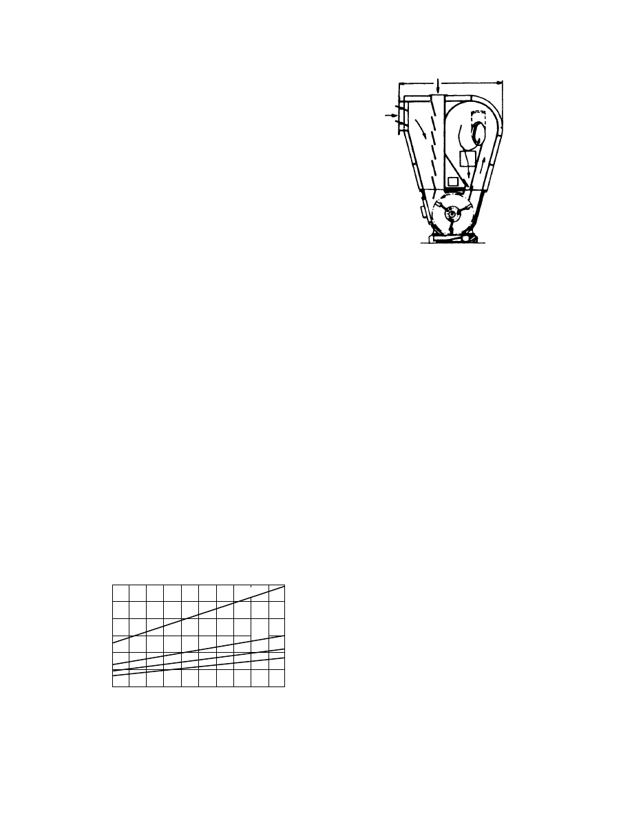
more. For drying ha rd and brown coal, beater mills
may be use d. A beater mill, includi ng the separato r, is
shown in Figure 43.19. Here, drying and grinding
proceed without the use of a fan. The mill consists of
a separat or hous ing and articulat ed rotat ing beater s.
The beaters num ber 2 to 12 per ro w and weigh 4 to
10 kg each. The be aters are made up of manganes e
steel, manganes e cast steel , cast iron, or carbon steel .
The be ater size can be different . The beater s are su b-
jected to abrasive wear and must be replac ed periodi c-
ally. In grindi ng quick cok e, the lifeti me of the beater s
is 200 to 400 h. The rotation al speed of the beater s
is 40 to 60 m/s; the num ber of revolut ions of the sh aft is
720 to 1420 rpm. Wet coal from a bin is charged by
gravity into the mil l through the feeder ; the hot air or
combust ion gases are suppli ed by lateral stub pipes.
The rotat ional moti on of beater s causes bounc ing of
coal particles up to a certa in he ight of the sh aft (up to
about 5 m), whi ch causes intens ive drying of co al as
well as grindi ng of coal g rains owin g to the direct
impac t. Coarser grains are recycle d for grindi ng; fine r
grains a re en trained, form ing a dust–air mixtu re su p-
plied directly to the boiler furnace .
The power consumpt ion for grindi ng is typic ally
15 to 20 kWh/Mg for ha rd co al and 4 to 14 kWh /Mg
for brown coal. The metal consumpt ion is 60 to 1 60 g/
Mg for hard coal, 20 to 80 g/Mg for brown coal, and
2000 g/Mg for qui ck coke. For coals at mois ture level s
of 10 to 14%, air at 300 to 400 8 C may be used as the
heatin g medium . W hen the mois ture con tent is above
15 to 25%, combu stion gases at tempe ratur e of 700 to
1000 8 C should be us ed. Coal at a high mois ture con -
tent (25 to 35%) shou ld be predri ed partially at the
chute to the mill by means of hot combust ion gases.
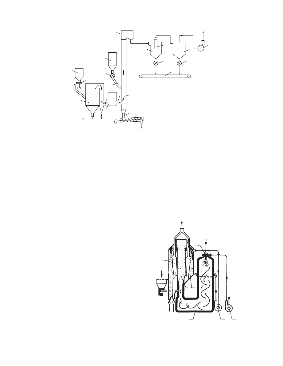
shows pulverized c oal produ ction
with simultaneous dr ying of coal. Wet coal is sup-
plied t o t he ball mill through the scales, feeder, and
drying tube. Hot air together with the coarse particle
recycling stream f rom t he separator i s directed t o the
mill and t he combustion gases are supplied t o the
drying tube.
43.2.9 S
HAFT
D
RYERS
A shaft dryer de signed by Konrer -Ledant for drying
of coal fed to cok e ovens is shown sch ematical ly in
. This dryer consists of two vertical
shafts of rectangular s ection. These r otating shafts,
fitted w ith paddles, a re intended t o fluff the coal
and t o transport i t downward. T he dryer has t wo
zone s, a drying zone and a cooling zone. C ombus-
tion gases g enerated in the c ombustion chamber
flow to the two vertical shafts, where they contact
with the wet coal moving down t he shaft. Cooling i s
achieved by means of ambient air s upplied t o the
lower part of t he shaft. The c ombustion gas is at
6508 C, and a ft er m ixi ng w it h the a ir leaving the
cooling zone its temperature drops to 250 to
3008C. At the dryer outlet the exhaust gas temperature
is 60 to 708C. In this type of dryer, the pressure drop
is about 700 Pa.
The combustion gases leaving the dryer shaft
are cleaned in a battery of cyclones and in a wet
scrubber. The dried coal withdrawn from the lower
part of the shaft by screw conveyor or a Redler-type
conveyor, the trough of which is hermetically sealed,
130
110
90
70
50
30
10
400 440 480 520 560 600
Combustion gases temperature before dryer (
⬚C)
Moisture content in combustion
gases before dryer (g/kg)
640 680 720 760 800
20%
30%
40%
x = 55%
FIGURE 43.18 Combustion gas temperature; relationship
between combustion gas humidity and coal moisture content.
Coal
Air
D
FIGURE 43.19 Mill-shaft dryer (beater mill including
separators).
ß
2006 by Taylor & Francis Group, LLC.
is transported to the coal bins. The entire coal-drying
and transport operation can be automated.
43.2.10 D
RYER WITH
M
OVING
B
ED
A modification of the shaft dryer is the convection
dryer with a moving bed (Figure 43.22), developed
and designed by the author of this chapter and used
for the drying of coal and quick coke. The particular
advantages of this dryer are observed when drying
quick coke, which has a high porosity and strong
abrasive properties. These properties considerably
hinder the use of fluid-bed dryers, spouted bed dryers,
and rotary dryers. The wet coal or quick coke is led to
the dryer by the stub pipe K
1
, and after passage
between the louver walls (1) and after drying, it is
introduced by stub pipe K
2
by means of a feeder (2).
Version 1 represents a dryer with gravity-assisted
movement of the bed, which is used for the drying
of quick coke.
Version 2, used for the drying of ground coal, has
a forced movement of the bed by means of the shelf
conveyor (3). Hot combustion gases or air are sup-
plied to the inlet chamber by stub pipe K
3
and after
passage through the bed leave the dryer by stub pipe
K
4
. The capacity of the dryer is controlled by varying
the speed of the feeders (2), as well as by alteration of
Air heater
Furnace
Cyclone
Separator
Feeder
Ball mill
FIGURE 43.20 Pulverized coal production with simultaneous drying.
Combustion gases
Fuel
Cyclones
Scrubber
Mud
Dry coal
Wet coal
Air
Air
FIGURE 43.21 Schematic of Konrer-Ledant-type shaft
dryer.
Version 1
K
1
K
1
K
3
K
4
K
4
K
5
K
2
K
2
7
2
6
Version 2
5
3
1
4
1
FIGURE 43.22 Convection dryer with moving bed.
ß
2006 by Taylor & Francis Group, LLC.

the sli t size of the stub pipes K
2
. The basic advan tage
of this dryer is its compact co nstruction an d sim ple
design, as well as the possibi lity of full automa tion. It
is pos sible to selec t the flow veloci ty to mini mize the
carryov er of particles from the bed; in many cases this
allows one to do away wi th any de dusting equipment .
Low-temper ature (150 to 200 8 C) was te comb ustion
gases from steam boilers can be us ed as the dry ing
medium . Low-temp erature operatio n great ly redu ces
the danger of ignition. Also, the drying rate pe r unit
volume is very high , up to about 0.2 kg/m
3
s at an
inlet air temperatur e of 200 8 C. For co mparison , for
rotary an d pneumat ic dr yers this amo unts to abo ut
0.014 and 0.14 kg/m
2
s, respect ively. Rotary, pneu -
matic, an d fluid -bed dryers are operate d at much
higher tempe ratures (400 to 800 8 C). The low veloci ty
(about 1 mm/ s) of movem ent of the coal be d consid-
erably de creases the wear of the dryer walls from
abrasio n. The he at consumpt ion is 2800 to 3500 kJ/
kg H
2
O. The drying tim e is the ke y design parame ter
for the calcul ation of the moving bed dr yer. The dry-
ing tim e is eq ual to the resi dence time in the dryer.
Hence the drying time has an effe ct on the velocity of
the bed in the dr yer. The drying time at co nstant
parame ters of the heatin g medium can be calcula ted
from
¼
1
£
[(X
1
X
cr
)
þ (X
cr
X
)] ln
X
cr
X
X
2
X
(43 : 41)
The drying co efficient £ charact erize s the rate of dry-
ing unde r con stant dr ying cond itions an d can be esti-
mated from the co rrelatio n
P
¼ 0: 469Re
0 :896
K
0 :633
H
d
e
1
§
u
§
g
1
(43 : 42)
The eq uivalent parti cle diame ter is calcul ated from
the form ula
d
e
¼
1
P
x
i
d
i
(43 : 43)
where x
i
¼ mass fract ion of diameter d
i
kg/kg,
u
¼ superfi cial gas veloci ty at inlet tempe ratur e, and
Q
¼ T
s
–T
D
¼ tempe ratur e differen ce betw een gas at
inlet T
s
and wet bulb tempe rature T
D
.
The be d pressur e dro p Dp through the layer of
coal can be calculated from the wel l-known Erg un’s
equati on:
Dp=H
¼ 150
(1
c
0
)
2
c
3
0
m
g
u
d
2
e
þ 1: 75
(1
c
0
)
c
3
0
§
g
u
2
d
e
(43 : 44)
43.2.11 S
UPERHEATED
S
TEAM
D
RYING OF
C
OAL
The ad vantage s of us ing su perheat ed steam as the
drying medium are well known an d noted in the
chapter on this subject in this handb ook. Among
those of major inter est in coal drying are no fire or
explosio n hazard, ability to dry at elevated tempe rat-
ures, fast er drying rates leading to smal l equ ipment
size, and others (Beeby and Potter , 1984; Weiss et al.,
1991; W olf et al., 1988).
Steam -fluidi zed be ds with steam have been in suc-
cessful ope ration in South Africa for ne arly a decade
(Faber et al., 1986). Fabe r et al. (1986) have sho wn
that fluid-bed steam dr ying of activated carbon pelle ts
saves en ergy (15% ) as well as capit al costs (14).
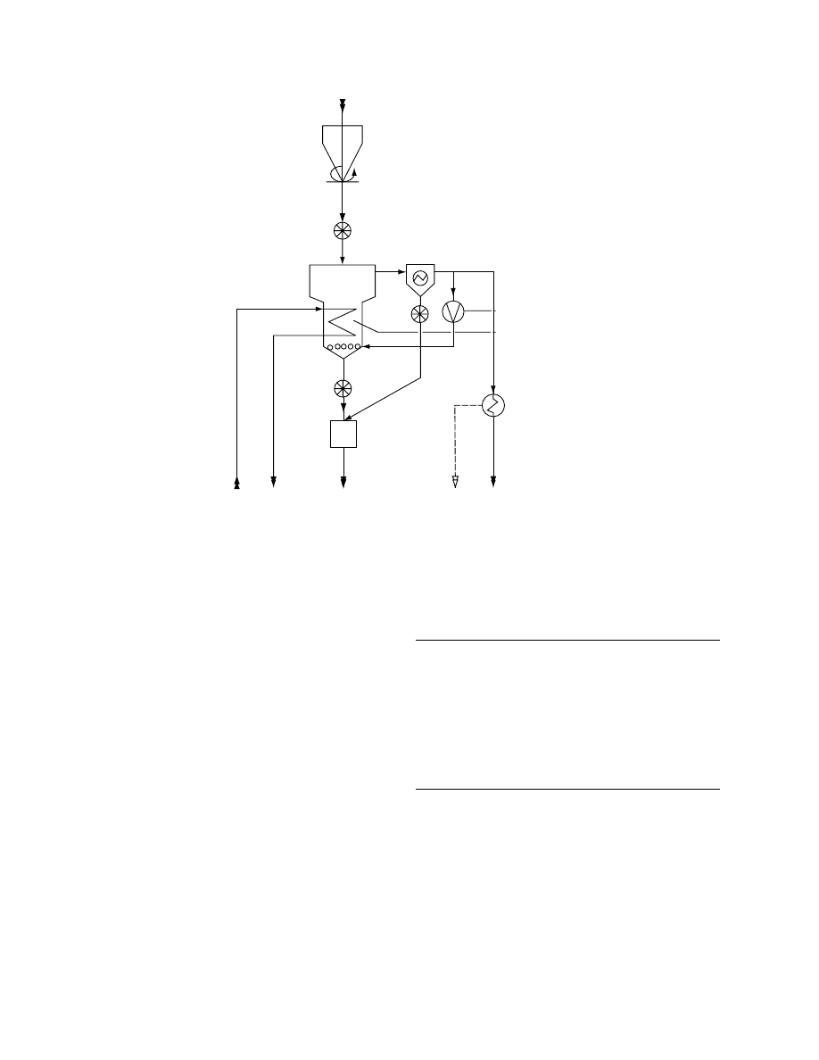
shows conceptually the steam-
fluidized bed drying (Dampf-Wirbelschicht-Trocknung
[DWT]) described by Weiss et al. (1991). Typical oper-
ating conditions for drying of brown coal are given
be lo w.
Fluid-bed pressure drop
and temperature
1–10 kPa, 110–1208 C
Fluidizing steam 15–25 kPa, superheated
Heating steam 400–500 kPa absolute, saturated
Coal grain size (feed) up to 6 mm
Coal grain size (output) up to 4 mm
Dry coal moisture 10–20%, dry basis
Note that RBC stands for raw brown coal. Dry
brown co al (DBC) is withdrawn through the inflow
plate. Exhaust steam is clear ed in an electrost atic
precipitat or and is partially recycled by a co mpres sor
as fluidizi ng steam . Excess steam is conden sed and
the late nt hea t is recover ed at 100 8 C. If this he at is
utilized elsewh ere, the ne t energy consumpt ion for
coal drying is very low. The internal heat exchange r
uses 4 to 5 bar satur ated steam and is taken out a s
clean condensate. The condensation temperature
must be 30 to 508C above the bed temperature for
efficient heat exchange between the bed and the
exchanger tubes. The bed is operated at a slight over-
pressure to eliminate air in leakage.
shows a schema tic of a steam -
fluidized bed dryer with combined generation of
power and heat. In a conventional coal-fired power
plant, up to two thirds of fuel energy is lost since the
latent heat of turbine exhaust steam is dissipated un-
used to the cooling water because of its low tempera-
ture level. In DWT process, the latent heat can be used
to dry the input coal. Figure 43.24 shows a coal-fired
power plant schematic with a circulating fluid-bed
ß
2006 by Taylor & Francis Group, LLC.
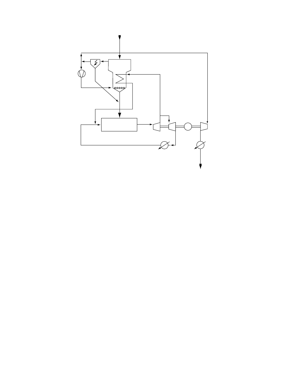
boiler, turbogenerator set, and condenser for turbine
exhaust steam. The top half is the DWT scheme. Use
of DWT is claimed to improve the energy efficiency
from 34 to 37%. If the DWT latent heat is also utilized
the efficiency is expected to rise to 39%. The reader is
referred to Faber et al. (1986) for details. Large-scale
pilot plants have successfully demonstrated this tech-
nology. The pilot-plant capacities range from 1 to 24 t/h
evaporation capacity. The latter can generate 20 t/h
of dry coal (12% moisture) from 44 t/h of raw coal
(60% moisture).
43.3 RECENT DEVELOPMENTS AND STATUS
OF COAL TECHNOLOGIES
Coal is a raw material for many chemical syntheses as
well as fuel. Coal is dried to increase its calorific value
and simplify loading, unloading, transport, and to
improve boiler combustion efficiency. It is also dried
for processes like briquetting, coking, gasification,
carbonization, and liquid fuel synthesis Coke oven
efficiency can increase 30 to 50% in preheating and
10 to 15% in drying.
Only high-moisture coals need to be dried prior
to usage. The type of dryer and extent of drying
required depends on many factors. Some of the prin-
cipal ones are the utilization of the mined coal,
whether it needs to be ground for firing into combus-
tion chambers and whether the application is near
‘‘mine-mouth’’ or far away from the mine. If the coal
contains substantial amounts of water (could be 50 to
70% wet basis depending on the coal), it may be
necessary to dehydrate it to reduce the transportation
cost. The calorific value also increases this way while
the combustion efficiency is also enhanced. Recent
work at Monash University in Australia has demon-
strated in laboratory and pilot tests that reduction of
moisture from Australian brown coal or lignite can
reduce greenhouse gas emissions from a power plant
by 30%
Direct dryers (e.g., rotary, pneumatic, fluid-bed,
vibrating fluid-bed, and shaft dryers) can be used with
hot air or combustion gases as drying media at 700 to
9008C before dryer and 60 to 1208C after dryer. It is
important not to have high oxygen content in the
drying gas to avoid explosion and fire hazard. This
is a key issue in coal drying. Low-rank coals can be
highly reactive and hence they are more susceptible to
fire and explosion hazard due to spontaneous com-
bustion. Hence indirect dryers have some advantages
RBC
DWT vapors
DWT
LP steam
LP condensate
Boiler
Turbine condensate
HP steam
12.5
MPa
HP
LP
8 kPa
100 kPa
500 kPa
G
~
Vapor
condensate
FIGURE 43.23 Steam-fluidized bed dryer (DWT, Dampf-Wirbelschicht-Trocknung) with internal heat exchangers.
ß
2006 by Taylor & Francis Group, LLC.
in this regard. Rotary dryers with indirect heating are
used for hard coals. These have higher energy effi-
ciency, about 3100 kJ/kg water evaporated. For air
fluidized bed dryers the corresponding figure is 3100
to 4000 kJ/kg water evaporated. A commercial vibra-
tory dryer for hard and brown coals (manufactured
by Escher-Wyss of Switzerland) uses a vibration fre-
quency of 50 to 100 Hz and amplitude of 0.5 to 3 mm
giving a conveying velocity in the range of 0.01 to
0.3 m/s with an angle of inclination of 58 to the
horizontal. Low gas velocities are needed since vibra-
tion suspends most of the pseudo-fluidized beds. The
efficiency is better than a conventional fluid-bed
employing high gas velocities. Attrition is reduced and
gas cleaning requirements minimized in a vibrated
bed dryer (Mujumdar, 1989; Erdez and Mujumdar,
1991).
In pilot trials Potter (Potter, 1979; Potter and
Keogh, 1979, 1981; Potter and Beeby, 1982, 1986;
Potter et al., 1988) have shown that extremely favor-
able heat transfer rates as well as drying efficiencies
are obtained when drying brown coal in a steam-
fluidized bed with internal heat exchanger tubes im-
mersed within it. Typical processing conditions are
reported as:
High tube temperature
140–1708C
Bed temperature
110–1278C
Minimum fluidizing velocity
5.7 cm/s (approx)
Steam temperature
130–1558C
Steam velocity (m/s)
0.20–0.30
Coal feed rate (kg/h) w.b.
40–70
Product (kg/h) w.b.
16–28
Drying rate (kg/h)
24–32
Using steam exhausted from one dryer stage as
carrier steam for another stage, multiple-effect oper-
ation (similar to that common to evaporators) can be
achieved yielding a steam economy of 1.9 for a triple-
effect dryer.
Potter et al. (1988) used a continuous fluid-bed dryer
for drying Victoria brown coal. The fluidized bed (FB)
dryer was 0.3
0.3 3 m (high) with four bubble caps to
distribute steam. The disengaging region was 2.5 m.
Both horizontal and vertical tube bundles were tried.
RBC (raw
brown coal)-
bunker
RBC discharge
Vapor dust
precipitation
Vapor compression
Vapor
condensor
Vapor
condensate
Energy
(~110
⬚C)
DBC
Condensate
Steam
(Dry brown
coal) cooler
FB (fluidized bed)
with heat exchanger
RBC
FIGURE 43.24 Steam-fluidized bed dryer with combined generation of power and heat.
ß
2006 by Taylor & Francis Group, LLC.

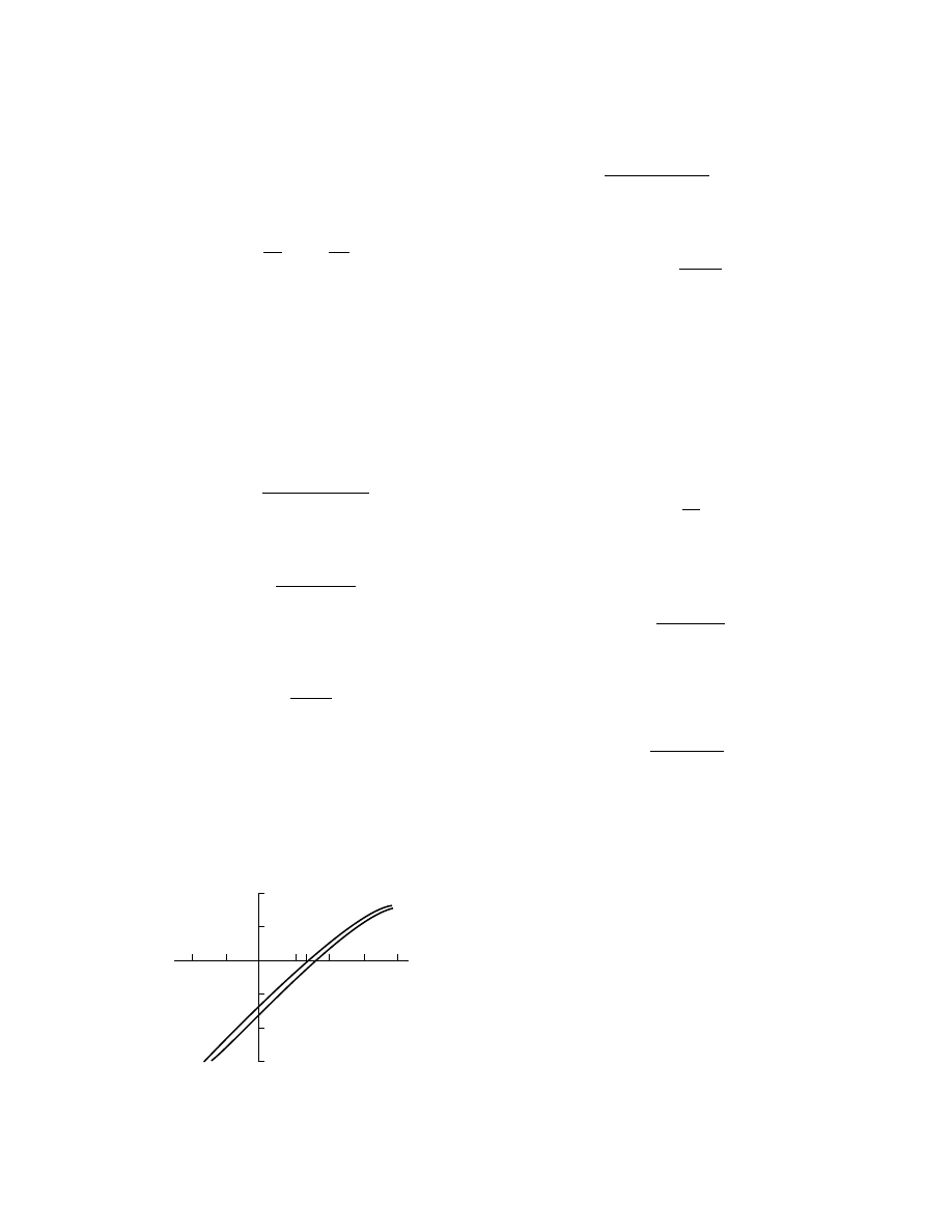
Faber et al. (1986) have compared drying rates in
air and steam-fluidized beds of pulverized coal. They
confirmed existence of the inversion temperature
above which steam drying is faster than air drying.
Above about 1808C the steam drying rate in the
constant-rate period in fluid-bed drying exceeds that
in (dry) air drying. For a 2000 kg/h dryer for alumina
they found the capital cost to be 20% lower for steam
dryer while the total energy cost was 15% lower. No
credit was given to the steam produced in the steam
dryer.
Faber et al. (1986) also report on a successful
industrial installation using steam dryer for activated
carbon pellets (2000 kg/h, dry basis) from an initial
moisture content of 50 to 2% (dry basis). The pellets
are dried to 8% on dry basis before they are fed to an
evacuated chamber in which the final moisture con-
tent of 2% is achieved. The steam enters the dryer at
3008C and leaves at 1508C. The steam discharged is
used to preheat the feed. The authors report smooth
operation of the dryer since 1985. The installed cost
of the steam drying system was 40% lower than that
for a conventional air dryer. The air dryer can operate
at a maximum temperature of 1258C to avoid com-
bustion in the dryer. The energy costs (1986 data)
were estimated to be about $3.60 per ton of dry
product in South Africa.
A Russian book on drying and thermo-aero clas-
sification of coal presents interesting results on steam
drying of 1- to 13-mm coal particles and volatiles
evolution during drying. Mujumdar (1990) notes
that in steam drying the drying time (actually resi-
dence time in dryer) does not affect the volatiles
liberation unlike air drying. Further, he found that,
under conditions of his experiment, the constant-rate
drying period is 6 to 7 times longer in steam drying
and the heat transfer rate is 1.7 to 2 times than that in
air drying. He also reports on favorable industrial
experience in steam-fluidized bed drying in a 35
9
12 m, 46 t/h of brown coal with an evaporative
capacity of 25 t/h. No details are given about the
steam reuse.
From energetic and safety viewpoints, super-
heated steam drying appears to be the most attractive
technology for drying of coal. This could be done
using a flash dryer, a fluid-bed dryer, a vibrating bed
dryer or a rotary dryer, if traditional dryer equipment
is to be used. A part of the energy can be supplied
indirectly using immersed heat exchangers. As
Mujumdar (1990) has noted there may be potential
to use variants of multistage impinging stream dryer
using superheated steam for coal drying applications,
but no work appears to be done yet on this design.
Furthermore, use of a two-dimensional design is
expected to allow modular design and reduced scale-
up problems. If used as a fuel after briquetting, there
may be opportunities to blend pulverized wet coal
with wood residues and various organic sludges either
before or after drying since these biomasses are also
excellent candidates for superheated steam drying.
43.4 DRYING OF LOW-RANK COALS
Low-rank coals (LRCs)—e.g., brown, lignite, and
subbituminous coals—represent nearly one half of
the estimated coal resources in the world and are the
only source of low-cost energy in many developing
nations. LRCs are typically present in thicker seams
with less overburden than bituminous coals, thus
making them recoverable by low-cost strip mining.
From a user angle, LRCs have a lower fuel ratio
(i.e., fixed carbon to volatile matter) and are typically
more reactive than bituminous coals; many also have
extremely low sulfur contents (a few tenths of 1%).
Low mining costs, high reactivity, and extremely low
sulfur content would make these coals premium fuels
if not for their high moisture levels, which range from
around 25% to more than 60%. Among coal import-
ers, high moisture creates a mistaken perception of
inferior quality and hence many positive features of
LRCs are neglected. LRCs can be combusted either
as a blending component with high-rank coal in exist-
ing boilers, or in new boilers designed for LRCs. For
example, more than one third of U.S. electrical power
currently comes from power stations that are fired by
LRCs. Until recently the high moisture levels of
LRCs have also excluded them from the rapidly
growing coal–water fuel (CWF) market. Of all the
coal-based alternative fuels, CWFs appear the most
promising (Willson et al., 1992).
It is now accepted that no single process can be
suitable as a universal drying technology for all
LRCs. The needs of the end user dictate the type of
process. If the end user requires dried lump coal for
stoker applications, a process that uses or generates
fines would not be a reasonable option. An end user
with advanced combustion applications will require
finely ground coal. From a producer’s angle, a pre-
ferred process could make use of both technologies:
one to produce sized dry coal and the other to make
coal–water fuel from the fines for a different market.
However, three stability issues must be solved before
bulk-dried LRCs can be used: (a) moisture reabsorp-
tion; (b) dust generation; and (c) spontaneous com-
bustion. Since the strength of LRCs is significantly
reduced when their gel-like structure is destroyed by
drying, the dried product breaks down rapidly, gen-
erating large amounts of dust, and becoming more
liable to spontaneous combustion.
ß
2006 by Taylor & Francis Group, LLC.

Direct drying of brown coal by recirculating boiler
flue gas or its equivalent, has become standard prac-
tice in Victoria, Australia. It should be noted that
significant drying occurs during normal coal grinding
and other operations associated with preparation of
the feed to a boiler.
Recently, a steam–fluidized bed drying process
being implemented at a plant operated by the State
Electricity Commission of Victoria, Australia (SECV)
uses a heat exchanger supplied by an external high-
pressure steam source to dry finely ground brown
coal. A tube network immersed in the bed supplied
heat. The high heat transfer rates of the bed, together
with condensing steam, yield a compact heat exchan-
ger. Water evaporated from the coal is used to fluidize
the system. Test results show that the water content of
Victoria’s brown coal can be reduced from 60 to 15%
and carbon dioxide (CO
2
) emissions can be decreased
to 17%.
In Australia, indirect drying has been used for
many decades to prepare brown coal for briquetting.
In this process, low-pressure steam is condensed on
the outside of tubes conveying brown coal to provide
process heat; the more water removed in liquid form,
the higher the efficiency. After reducing the moisture
to nominally 15%, dried brown coal is compacted into
strong briquettes using stamp presses.
43.5 HOT OIL DRYING
Hot oil is an alternative drying medium used by a
number of process developers as early as 1926. In the
two-stage Carbontech process, raw coal is first dried
in hot oil. Most of the oil is recovered in the second-
stage flue gas stripper. Some of the oil is absorbed,
which allegedly helps to stabilize the product and
increase its heating value. The process costs for this
system will depend on the amount of oil that can be
economically recovered.
The Exxon donor solvent, direct liquefaction
process also used hot oil drying. In this process,
LRC is dried by a high-pressure hydrogenation
reactor contact with hot recycle hydrogen donor
solvent prior to entering. Unfortunately, no data
were developed for solvent recovery after drying,
because the dried coal and vehicle solvent were
reacted immediately with hydrogen in the liquefaction
reactor.
Other methods have been tested to improve
the stability of the dried LRC, including spraying
with residual tars or oils and briquetting or palle-
tizing dried pulverized coal. All of these additional
processing steps increase the cost of the final pro-
duct and must be evaluated on a site and coal-
specific basis.
43.6 HOT WATER DRYING
Hot water drying (HWD) developed at EERC, is
a drying process that produces a safe, quasiliquid
fuel. This technology features high temperature,
high pressure nonevaporative drying that removes
much of the inherent moisture and allows the produc-
tion of CWFs with solid loading in the range of those
of commercial bituminous CWFs.
In HWD process, ground LRC is treated at coal-
specific temperatures, beginning at as low as 2408C,
and the corresponding saturated steam pressure for
less than 10 min. Moisture is removed from the coal
by expansion and expulsion from the micropores by
CO
2
, which is liberated during decarboxylation. Devo-
latilized tars/oils, being hydrophobic, remain on the
coal surface in the pressurized aqueous environment.
It is hypothesized that this produces a uniform coating
that seals the micropores and limits moisture re-
absorption, which is a major advantage of the process.
Because the coating retains most of the LRC’s volatile
matter, high energy recovery and excellent combustion
performance can be obtained. The developers claim
that alkali cations, a major source of boiler fouling,
associated with the carboxyl groups, are released in the
aqueous phase in their process and are removed during
the final mechanical dewatering step.
The technical feasibility of HWD and low-rank
coal–water fuel (LRCWF) production has been dem-
onstrated in a 7.5-tpd pilot plant at EERC with LRCs
from around the world. As a general rule, the energy
densities of LRCWFs produced after HWD are
around 30% for subbituminous coals, 50% for lignite,
and >100% for brown coals, vs. those prepared from
raw coal. Costs of dewatering will vary with coal
grade and location.
Currently the successful commercial LRC drying
processes appear to be those in which the dried LRC
is utilized immediately and not stored. When stored,
the products from most drying systems can have sta-
bility problems, which result in excessive fines and
spontaneous heating.
43.7 COMBINED GRINDING AND DRYING
Often coal is ground prior to utilization. Heat pro-
duced during grinding can reduce the moisture con-
tent significantly while reducing the particle size. In
some other applications, e.g., drying of sludge from a
deinking plant, initial moisture content of 54% can be
reduced to as low as 12% (wet basis) during grinding.
This also destroys any pathogens that may be present.
One of the commercial grinder dryers of interest
to coal drying is the KDS Micronex grinder/dryer.
ß
2006 by Taylor & Francis Group, LLC.

A typical KDS grinder chamber has a diameter of
1.3 m and encloses a set of 8 spinning chains and a
stationary torus above it. The chains are spun hori-
zontally at high rotational speeds; the chain tip speed
can reach about 200 m/s causing high frictional heat-
ing due to aerodynamic drag. The bottom surface of
the torus that is flat provides a surface for the par-
ticles to collide on and shatter. This results in grinding
action accompanied by drying. The mechanism of
drying is partly thermal and partly mechanical dewa-
tering. This saves energy for drying. Air temperatures
in the chamber can reach between 70 and 908C. For a
typical application for drying coal at the feed rate of
about 2200 kg/h with initial moisture content of 15%
on wet basis the manufacturer reports final moisture
content of 4% on wet basis, and average particle
diameter of 75 mm and energy consumption of 2020
kJ/kg, which is less than the latent heat of vaporiza-
tion for water. Note that the Micronex unit claims to
consume about 70% less energy than a traditional
rotary dryer since a part of water removal takes
place in liquid phase. In fact for drying of deinking
sludge, manure, the manufacturer claims energy con-
sumption of 975 to 1700 kJ/kg. The electrical power
consumption for the coal dryer/grinder is rated at
140 kW. There appears to be no commercial installa-
tion for coal drying using this technology at this time.
43.8 FLEISSNER PROCESS
This is a very old process for drying low-rank coals,
first developed in Austria in mid-1920s. This process
consists of treating the low-rank coal in a saturated
steam environment that avoids vaporization of the
moisture in the coal. The coal particle ‘‘sweats’’ ef-
fectively and no evaporation occurs. As noted earlier
decarboxylation occurs during this process causing
some shrinkage of the dried product and a reduction
of its equilibrium moisture content. The U.S. Bureau
of Mines evaluated this process for dewatering of
lignites and subbituminous coals in the 1940s and
1950s. The more recent nonevaporative drying pro-
cesses for coal essentially appear to be based on the
principle of the Fleissner process.
43.9 A NONTHERMAL BIOMASS DRYER
Recently Gulf Tex Environmental Services of Texas,
United States have developed a new nonthermal dryer
called Pulverizing Air Dryer (PAD). This dryer does
not use heat but can reduce moisture content from 80
to as low as 10% depending on the biomass. The PAD
technology uses high-velocity air streams to accelerate
and then collide against the particle streams subjected
to drying. Interestingly they claim that the particles
can range from large rocks to sludge material. The
PAD process affects surface, loose matrix-bound as
well as intracellular moisture. The drying chamber is
designed as a cyclone in which the centrifugal drying
chamber separates the material by density, with water
coming out from the top and the dry material out
from the bottom. Capacities of up to 20 t/h are pos-
sible with this novel dryer. According to the manu-
facturer the capital and energy costs of this PAD
dryer for coal are low and can result in a saving of
up to $150 per ton of the dry product compared with
a thermal dryer. Note that this figure is probably
valid for a specific coal at 2004 prices. Unfortunately,
no technical details are available on this apparently
interesting new technology.
43.10 MECHANICAL THERMAL
EXPRESSION PROCESS
A process that uses mild heating and mechanical
squeezing, and appropriately termed the Mechanical
Thermal Expression (MTE) process has generated
renewed interest in an essentially nonthermal dehy-
dration process for high-moisture brown coals and
lignites. Developed at Monash University, this pro-
cess uses mechanical expression (1 to 10 MPa) at
elevated temperatures. The high pressure does not
permit phase change of water and thus makes it
more energy-efficient. When depressurized the wet
coal also undergoes some flash evaporation and re-
moves about 7% of the moisture. Changes in physical
structure and chemical changes are hypothesized to
be responsible for dewatering of the coal despite im-
mersion in water. The precise mechanics are still un-
known although there are effects of shrinkage,
removal of trapped air, and changes in physical and
chemical structure making the coal particles possibly
more hydrophobic that make the dehydration effect-
ive. Capital costs involved in this process are still not
clear but the process has definite potential. Tests on a
10 t/h pilot plant are under way in Australia at the
present time (Clayton et al., 2006). Interestingly, this
process has been successfully tested on laboratory
scale for dewatering of biomass, e.g., bagasse,
sludges, and biosolids
43.11 CONCLUSION
With rising energy costs and dwindling supplies of oil,
there is little doubt that within the next decade coal
technologies will play very significant role in meeting
the world’s energy needs. Coal gasification and lique-
faction will become increasingly important all around
ß
2006 by Taylor & Francis Group, LLC.

the world to reduce dependence on oil and gas. Many
of these processes need conditioning of the coal used
that includes reduction of its moisture content to
desirable levels for the processes involved. The
world reserves of low sulfur but high moisture content
are rather extensive and must be utilized cost-
effectively by reliable energy-efficient and safe drying
technologies. Different technologies will be needed
depending on whether the coal is used near the
mines or after shipping over great distances. Cost of
transportation can be reduced by lowering the mois-
ture content but there is danger of autoignition in
storage due to most such coals being highly reactive.
Thus, drying, storage, and handling of dried coal pose
many technological challenges.
Over the last three decades over 300 patents were
issued by the U.S. Patent Office with the word dryer
or drying of coal in their titles. Of course, only a few
of these patented technologies are truly viable. Many
of the ideas suggested are not practical, e.g., use of
acoustic radiation, ultrasonics, and super critical ex-
traction to reduce sulfur content. Some suggest rather
complex designs of rotary dryers that are unlikely to
be cost-effective. For example, U.S. Patent 4,014,106
(1997) describes a rotary dryer for coal comprising of
an insulated stationary cylinder within which an
open-ended metallic cylindrical tube is rotated co-
axially in an almost horizontal position. Wet particles
are fed at the open end and hot air is circulated
between the stationary cylinder and the tube. Metal
balls are mixed with the wet material in the rotating
tube. Perforated fins and baffles extend from the ex-
ternal wall of the tube to enhance conductive heat
transfer to the tube and the metal balls. The dried
coal is discharged at the opposite end through a
screen section of the tube. This patent also suggests
additives to the wet mix to coat the dried particles for
reducing dusting or to prepare the mix for palletizing.
There is no reported commercial application for this
process. Although technically sound, it appears to be
rather complex for industrial application.
On the other hand, superheated steam seems to
provide all the required advantages but few vendors
have developed these technologies for coal and for the
large-scale operations necessary. The drying condi-
tions will need to be optimized for specific grades of
coal and also the utilization of the product. As coal
needs to be ground for many applications a combined
grinder–dryer is definitely an attractive option and
much effort is being directed in this area as well.
Drying in this case a desirable by-product of the
grinding operation but supplementary drying may
be required for high moisture coals since here electri-
city is used for the grinding operation.
NOMENCLATURE
a
exposed surface per unit volume dryer, m
1
C
p
heat capacity at constant pressure, J
kg
1
K
1
d
e
equivalent diameter of particle, m
d
p
particle diameter, m
D
diameter, m
g
acceleration of gravity, m
s
2
G
gas flow rate, kg
s
1
h
1
space height upon bed, m
h
c
convective heat transfer coefficient, W
m
2
K
1
H
height of bed, m
H
0
(h
0
)
initial height of bed, m
J
humid gas enthalpy, J
kg
1
k
coefficient
_
L
L
solids flow rate, kg
s
1
L
mass of solids, kg
L
length, m
n
speed of rotation, s
1
; min
1
N
F
drying rate per unit exposed surface,
kg
m
2
s
1
; kg
m
2
N
v
drying rate per unit volume, kg
m
3
s
1
;
kg
m
3
h
1
Q
heat quantity, J
S
cross-sectional area, m
2
S
surface, m
2
T
temperature, K
T
m
temperature of solids, K
u
velocity, m
s
1
u
g
gas velocity, m
s
1
u
cr
critical velocity, m
s
1
u
0
sedimentation velocity, m
s
1
V
volume, m
3
_
V
V
g
cubic gas rate, m
3
s
1
W
moisture content, kg
X
moisture content
X
*
equilibrium moisture content
X
cr
critical moisture content
Greek Symbols
a
angle of inclination, rad, degree
b
loading factor, 1
DH
latent heat of vaporization, J
kg
1
Dp
pressure drop, Pa
u
temperature difference, K
u
m
mean temperature difference, K
l
thermal conductivity, W
m
1
K
1
m
g
dynamic viscosity of gas, Pa
s
y
g
kinematic viscosity of gas, m
2
s
1
z
g
gas density, kg
m
3
z
s
density of solids, kg
m
3
ß
2006 by Taylor & Francis Group, LLC.

z
u
bulk density, kg
m
3
t
time, s
f
apex angle, rad, degree
£
drying coefficient
c
porosity of bed
c
0
porosity of solid (filtration) bed
Other
1
¼ inlet
2
¼ outlet
Commonly Used Dimensionless Group
Ar
¼
gd
3
p
v
2
g
§
s
§
g
§
l
Archimedes number
Nu
¼
h
c
d
p
l
Nusselt number
Pr
¼
C
p
m
g
l
Prandtl number
Re
¼
ud
p
u
g
Reynolds number
P
¼
£d
e
v
a
g
Drying number
K
¼
DH
C
p
Q
Condensation number
BIBLIOGRAPHY
Beeby, C. and Potter, O.E., Proceedings of the 4th Inter-
national Drying Symposium, Kyoto, Japan, 1984.
Also in Drying ’85, Toei, R. and Mujumdar, A.S.
(Eds.), Hemisphere, New York, 1984.
Clayton, S.A., Scholes, O.N., Headly, A.F.A., Wheeler,
R.A., McIntosh, M.J., and Huyah, D.Q., Dewater-
ing of biomaterials by mechanical thermal expres-
sion, Drying Technology, Vol. 24, No. 7, 2006.
Erdez, K. and Mujumdar, A.S., Vibro-fluidization, A Re-
search Monograph, 1991.
Faber, E.-F., Heydenrych, M.D., Seppa, R.U.I., and Hicks,
R.E., Drying ’86, Vol. 2, Mujumdar, A.S. (Ed.),
Hemisphere/Springer-Verlag,
New
York,
1986,
pp. 588–594.
Faber, E.F., Heydenrych, M.D., Seppa, R.V.I., and Hicks,
R.E., A Techno-economic compression of air and
steam drying, Drying ’86, Vol. 2, Mujumdar, A.S.
(Ed.), Hemisphere, New York, 1986, pp. 588–594.
Keey, R.B. Introduction to Industrial Drying Operations,
Pergamon Press, Oxford, 1978.
Kneule, F., Das Trocknen, Sauerlander, Aurau und Frank-
furt am Main, 1975.
Krischer, O., and W. Kast, Die Wissenschaftlichen Grundla-
gen der Trocknungstechnik, Springer, Berlin, 1978.
Kro¨ll, K., Trokner und Trocknungsverfahren, Springer,
Berlin, 1978.
Mujumdar, A.S., Keynote Lecture: Aerodynamics, Heat
Transfer and Drying in Vibrated Fluidized Beds,
Heat Mass Transfer ’89, Australasian Conference,
Christchurch, New Zealand, May 1989.
Mujumdar, A.S., Superheated Steam Drying: Principles,
Practice and Potential for Use of Electricity,
Canadian Electrical Association, Montreal, Que-
bec, Canada, Report No. 817 U 671, 1990, p. 127.
Pikon´, J., Wasilewski, P., and Mitka, B., Suszenie i
podgrzewanie wegla wsadowego do produckcji
koksu, Wiadomos´ci Hutnicze No. 11, Slask-
Katowice, 1972.
Pikon´, J., Suszarka konwekcyjna z przesuwnym złoz˙ em, In
z˙ ynieria I Aparatura Chemiczna No. 2, NOT,
Warszawa, 1976.
Pikon´, J., Aparatura Chemiczna, PWN, Warszawa, 1978.
Potter, O.E., Dry as dust or how to dry particles with energy
economy, Chem. Eng. Aust., 1979, pp. 26–29.
Potter, O.E. and Keogh, A.J., Cheaper power from high
moisture brown coals—part I and II, J. Inst. En-
ergy, 1979, pp. 143–149.
Potter, O.E. and Keogh, A.J., Drying high moisture coals
before liquefaction or gasification, Fuel Process
Technol., 1981, pp. 217–277.
Potter, O.E. and Beeby, C., Modeling tube-to-bed heat
transfer in fluidized bed steam drying, Proceedings
of the 5th International Drying Symposium IDS ’86,
Mujumdar, A.S. (Ed.), Cambridge, MA, USA,
Hemisphere, New York, 1986.
Potter, O.E., Beeby, C., et al., Drying in steam-heated steam
fluidized beds, Proceedings of the 4th International
Drying Symposium, Birmingham, England, 1982,
pp. 115–123.
Potterm, O.E., Guang, L.X., et al., Some design aspects
of steam-fluidized heated dryers, Proceedings of
the 6th International Drying Symposium IDS ’88,
France, 1988.
Romankow, P.G. and Raszkowskaja, N.B., Suszka we
wzweszennom sostojanii, Chimja, Leningrad, 1979.
Todes, O.M. and Citowitz, O.B., Aparaty z kipiaszczym
zernistym słojem, Chimja, Lenningrad, 1981.
To´ei, R., Dryer, Nittsukan-Kogyo, Tokyo, 1966.
Weiss, H.-J., Klutz, H.-J., and Hamilton, C.-J., VGB Kraft-
werkstechnik, 71(7):664, 1991.
Willson, W.G., Young, B.C., and Irwin, W., 1992,
Low-rank coal drying advances, Coal, Aug. 1992,
pp. 24–27.
Wolf, B., Zabinski, H., and Lange, A., Neue Bergbantech-
nik, 18(2):61, 1988.
ß
2006 by Taylor & Francis Group, LLC.
Document Outline
- Table of Contents
- Chapter 043: Drying of Coal
- 43.1 Introduction
- 43.2 Typical Designs of Dryers Used for Coal Drying
- 43.2.1 Rotary Dryers
- 43.2.2 Rotary-Tube Dryer
- 43.2.3 Chamber Dryer Equipped with Stirrers
- 43.2.4 Pneumatic Dryers
- 43.2.5 Fluid-Bed Dryers
- 43.2.6 Fluid-Bed Dryer with Fountain Bed (Spouted bed)
- 43.2.7 Vibratory Dryers
- 43.2.8 Mill-Type Dryers
- 43.2.9 Shaft Dryers
- 43.2.10 Dryer with Moving Bed
- 43.2.11 Superheated Steam Drying of Coal
- 43.3 Recent Developments and Status of Coal Technologies
- 43.4 Drying of Low-Rank Coals
- 43.5 Hot Oil Drying
- 43.6 Hot Water Drying
- 43.7 Combined Grinding and Drying
- 43.8 Fleissner Process
- 43.9 A Nonthermal Biomass Dryer
- 43.10 Mechanical Thermal Expression Process
- 43.11 Conclusion
- Nomenclature
- Bibliography
Wyszukiwarka
Podobne podstrony:
Modeling with shrinkage during the vacuum drying of carrot (daucus carota) (Arévalo Pinedo, Xidieh M
Influence of drying methods on drying of bell pepper (Tunde Akintunde, Afolabi, Akintunde)
10 desulfurization of coal
Far infrared and microwave drying of peach (Jun Wang, Kuichuan Sheng)
Microwave Application in Vacuum Drying of Fruits (Drouzaf, H SchuberP)
Microwave vacuum drying of model fruit gels (Drouzas, Tsami, Saravacos)
041 Drying of Polymers
039 Drying of Biotechnological Products
042 Drying of Enzymes
Modeling and minimizing process time of combined convective and vacuum drying of mushrooms and parsl
022 Drying of Fish and Seafood
026 Drying of Herbal Medicines and Tea
Characterization of microwave vacuum drying and hot air drying of mint leaves (Mentha cordifolia Opi
Microwave Application in Vacuum Drying of Fruits (Drouzaf, H SchuberP)
040 Drying of Coated Webs
Microwave Drying of Parsley Modelling, Kinetics, and Energy Aspects
Microwave Finish Drying of Diced Apples in a Spouted Bed
więcej podobnych podstron