
Initial Print Date: 10/06
Table of Contents
Subject
Page
Explanation of the Kamm's Circle using an Example . . . . . . . . . . .6
E70 Chassis and Suspension . . . . . . . . . . . . . . . . . . . . . . . . . . . . . . . . . .8
Track Width, General . . . . . . . . . . . . . . . . . . . . . . . . . . . . . . . . . . . . .10
Wheelbase, General . . . . . . . . . . . . . . . . . . . . . . . . . . . . . . . . . . . . . .10
Chassis and Suspension Overview . . . . . . . . . . . . . . . . . . . . . . . . . . . . . .11
Front Axle . . . . . . . . . . . . . . . . . . . . . . . . . . . . . . . . . . . . . . . . . . . . . . . . . .11
Rear Axle . . . . . . . . . . . . . . . . . . . . . . . . . . . . . . . . . . . . . . . . . . . . . . . . . .11
Dampers/Suspension . . . . . . . . . . . . . . . . . . . . . . . . . . . . . . . . . . . . . . .12
Brakes . . . . . . . . . . . . . . . . . . . . . . . . . . . . . . . . . . . . . . . . . . . . . . . . . . . . .12
Steering . . . . . . . . . . . . . . . . . . . . . . . . . . . . . . . . . . . . . . . . . . . . . . . . . . .12
Wheels and Tires . . . . . . . . . . . . . . . . . . . . . . . . . . . . . . . . . . . . . . . . . . .12
Front Axle . . . . . . . . . . . . . . . . . . . . . . . . . . . . . . . . . . . . . . . . . . . . . . . . . .13
Virtual Pivot Point . . . . . . . . . . . . . . . . . . . . . . . . . . . . . . . . . . . . . . . . . . .15
Cast Aluminum Spring Support (body side) . . . . . . . . . . . . . . . . . . . .16
Extended Hump Rims (EH2+) . . . . . . . . . . . . . . . . . . . . . . . . . . . . .23
Tire Failure Indicator RPA . . . . . . . . . . . . . . . . . . . . . . . . . . . . . . . . .23
RSC tires with emergency running properties . . . . . . . . . . . . . . .23
E70 Chassis Dynamics
Revision Date:

2
E70 Chassis Dynamics
Chassis Dynamics
Model: E70
Production: From Start of Production
After completion of this module you will be able to:
• Understand Principles of Chassis Dynamics on the E70
• Describe Front and Rear Axle Changes
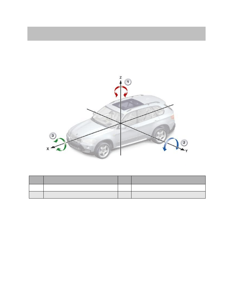
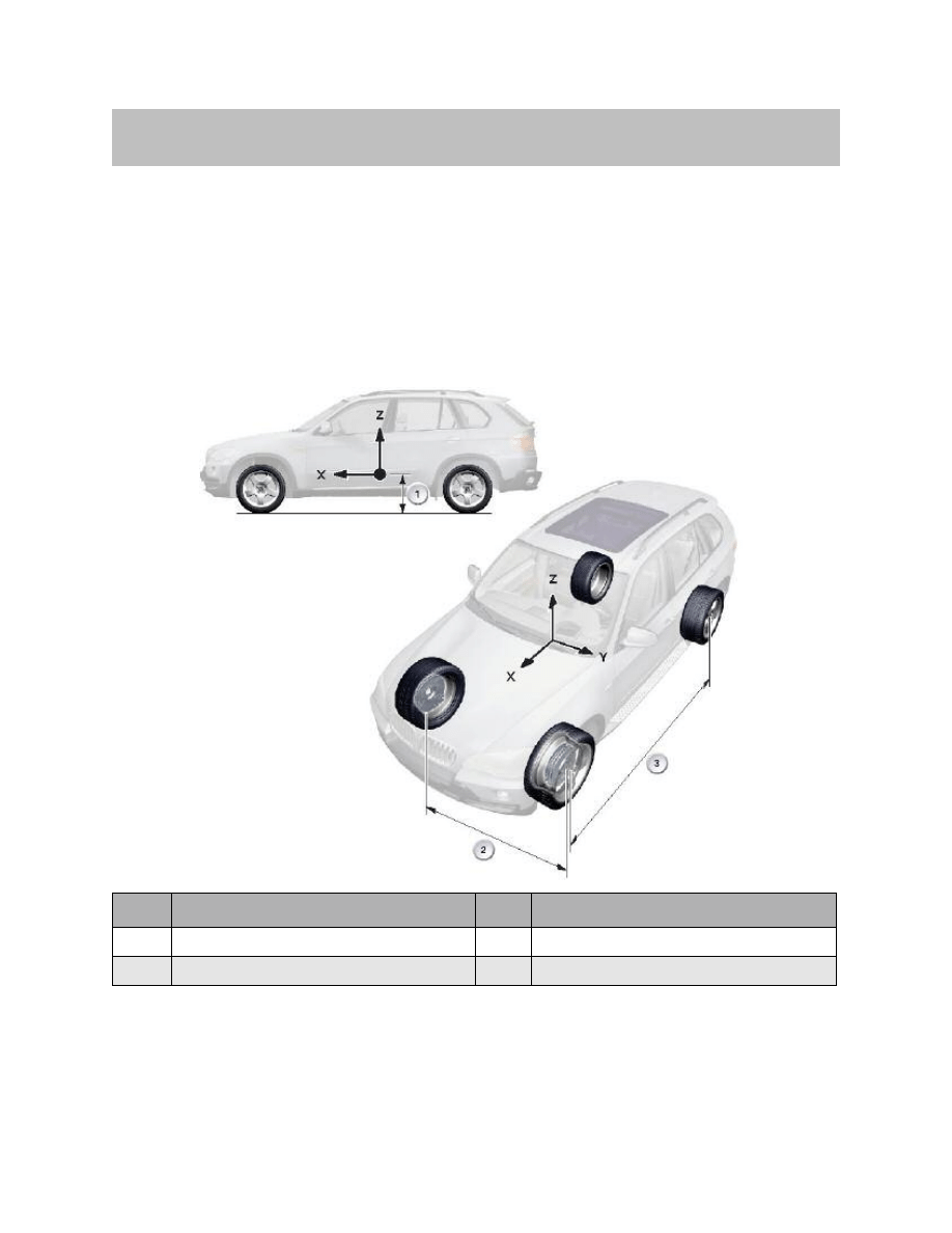
Certain dynamic influences cause movements in the vehicle body. These movements
can be subdivided into and represented as three categories.
A coordinate system can be constructed for this with three spatial coordinate axes,
which allows this degree of freedom to be defined.
• Longitudinal dynamics:
The main direction of movement and the direction of travel is defined by the x or
longitudinal axis of the coordinate system. Situations involving longitudinal dynam-
ics, such as accelerating or braking, cause the vehicle to pitch and result in a move-
ment about the y axis.
• Lateral dynamics:
Lateral dynamics occur when the direction of movement is along the y or lateral
axis, as is the case with steering or swerving. This causes, among other things, the
vehicle to roll and move about the x axis.
3
E70 Chassis Dynamics
Driving Dynamics
Index
Explanation
Index
Explanation
1
Yawing (about the vertical axis)
3
Rolling (about the longitudinal axis)
2
Pitching (about the vertical axis)
Vertical Dynamics
If the body moves along the z or vertical axis, this is known as vertical dynamics and
constitutes oscillating up and down movements of the body, e.g. when “kangarooing” the
vehicle.
If there is still movement about the z or vertical axis of the vehicle, this is known as
yawing. This type of movement occurs during understeer or oversteer and is demon-
strated by drifting when the vehicle is being driven sportily, for example.
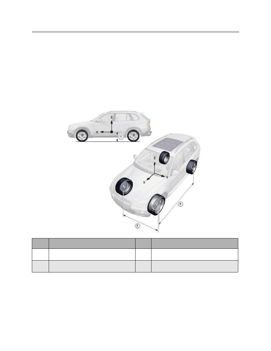
These basic dynamic characteristics depend specifically on the following vehicle
dimensions.
The position of the center of gravity in the vehicle, its distance from the road surface, the
wheelbase and the track width are decisive geometric parameters that shape the
dynamic behavior of a vehicle.
4
E70 Chassis Dynamics
Index
Explanation
Index
Explanation
1
Distance for the center of gravity
from the road surface
3
Wheelbase
2
Track width
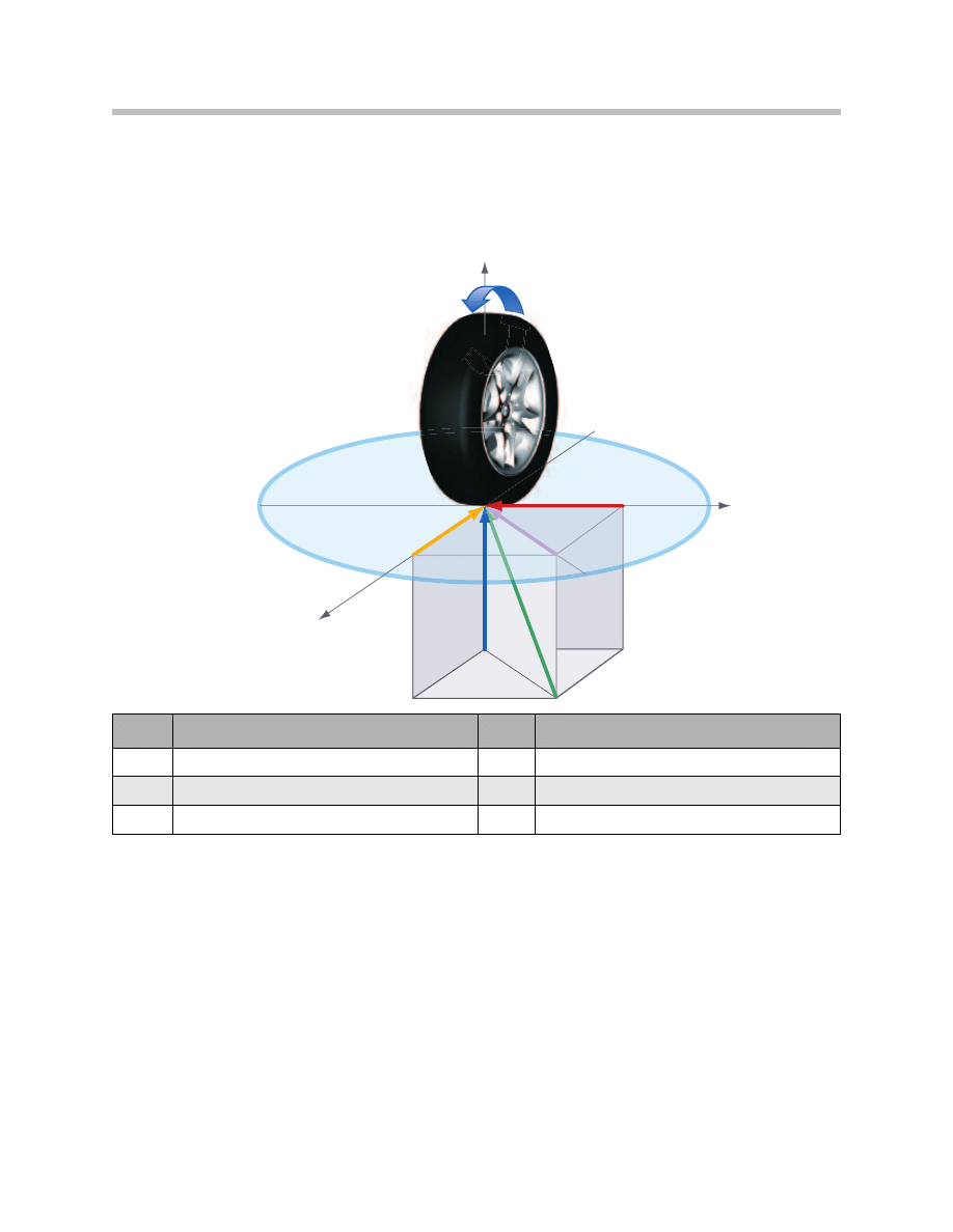
Forces at the Wheel
The forces acting on the contact surface between the tire and the road are also
subdivided into the three main directions.
The vertical force is fundamental. This acts vertically to the road and corresponds to the
load on the tire. The maximum transferable lateral and tangential tire forces are the prod-
uct of the vertical force and the adhesion coefficient.
The radius of the Kamm's circle shows this mathematical relationship graphically. It is
also possible to see the dependency between the tangential and lateral forces in the
Kamm's circle.
5
E70 Chassis Dynamics
z
x
y
K
F
RE
F
RR
F
S
F
U
F
V
T
F
0
4
-
5
4
5
4
Index
Explanation
Index
Explanation
K
Kamm’s circle
Fv
Vertical tire force
Fu
Tangential tire force
FRE
Resulting force on surface
Fs
Lateral tire force
FRR
Resulting force in space

Explanation of the Kamm's Circle using an Example
If a lateral tire force is acting on the wheel, a braking or accelerating force (tangential tire
force) can only build up in a longitudinal direction up to the maximum total force (resulting
force on surface). When this is reached, the wheel locks or spins.
Conversely, only a limited lateral cornering force (lateral tire force) can be achieved under
braking. If this is exceeded, the wheel slips in a lateral direction. This causes the vehicle
to skid. If a braking force takes effect, the full lateral cornering force can be established in
accordance with the radius of the Kamm's circle.
In the same way, the full braking or acceleration force can be established when the
vehicle is driving straight ahead (again according to the radius).
This relationship shows that acceleration or braking that is too rapid under cornering can
cause the vehicle to skid, as any longitudinal force on the wheel, whether it serves to
accelerate or brake, inevitably results in a failure of the lateral cornering forces.
The radius of the Kamm's circle depends on the friction coefficient between the tire and
the road, i.e. on the tire, the road surface and the road conditions. If the road is wet, for
example, the radius is considerably smaller than if the road is dry.
Interrelationships between the effects of the dynamic driving systems
The possible effectiveness of modern dynamic driving systems is based only on the
interrelationship between the tires and the road.
In order to classify and differentiate between the many systems in the E70, they are
described in three separate Reference Information documents:
• E70 longitudinal dynamics systems - The following dynamic driving systems act on
the tangential wheel forces:
– ABS
– ASC
– DSC
– MSR
These influence the translatory (longitudinal) movement along the x axis and the rotational
movement about the y axis.
• E70 lateral dynamics systems - Lateral wheel forces are primarily generated by the
steering angle, i.e. they are influenced by the power steering and Active Steering on
the front axle. The most significant effect occurs as a rotational movement about the
z axis.
• E70 vertical dynamics systems - The following essentially act upon the vertical
wheel forces and the wheel contact forces:
– VDC
– EHB
– ARS
6
E70 Chassis Dynamics
This affects the translatory movement along the z axis and, depending on the system, the
rotational movement about the x axis for ARS or about the y axis for EHC.
Furthermore, the rotational movement about the z axis due to altered wheel contact
forces is also influenced by ARS (actual dynamic significance of the anti-roll bar).
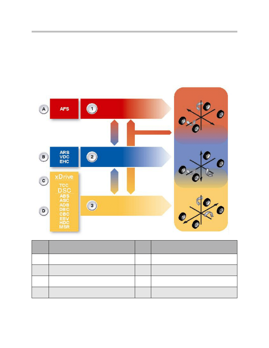
The complexity of the relationships and the reciprocal influencing of the tire forces and
therefore the vehicle movement should be made clearer by the following graphic.
7
E70 Chassis Dynamics
Index
Explanation
Index
Explanation
1
Lateral tire forces/lateral dynamics
B
Ride comfort
2
Vertical tire forces/vertical dynamics
C
Traction
3
Tangential tire forces/longitudinal dynamics
D
Safety when braking and accelerating
A
Handling
Through intelligent design layout and optimum package space utilization on the E70,
the basis has been created for distinctly increasing the driving dynamics while improving
comfort and vehicle handling. At virtually identical wheel loads, a greater track width and
a larger wheelbase have been realized compared to the predecessor, the E53.
While essentially retaining the same center of gravity, the best prerequisites have been
created for meeting the target "Best in segment" with the new chassis and
suspension of the E70.
E70 Chassis and Suspension
8
E70 Chassis Dynamics
Index
Explanation
Index
Explanation
1
Center of gravity
3
Wheelbase
2
Track width, front

Comparison
9
E70 Chassis Dynamics
E53
E70
Front axle
Double pivot spring strut front axle
Double wishbone front axle
Suspension/damping, front
Steel spring or air spring
Steel spring
Anti-roll bar, front
Mechanical
Mechanical or Hydraulic
Rear axle
Integral IV
Integral IV
Suspension/damping, rear
Steel spring or air spring
Steel spring or air spring
Anti-roll bar, rear
Mechanical
Mechanical or Hydraulic
Brake, front
Brake disc diameter up to 356 mm
Brake disc diameter up to 365 mm
Brake, rear
Brake disc diameter up to 324 mm
Brake disc diameter up to 345 mm
Parking brake
Drum brake, mechanical
Drum brake, with electro-mechanical
parking brake (EMF)
Wheels/tires
Standard tires
Run flat tires
Steering
Power steering or Servotronic
Power steering or active steering

Track Width, General
The size of the track width at the front and rear has a decisive influence on the cornering
characteristics of the vehicle and its tendency to roll.
• The track width should be as large as possible, however, it cannot exceed a defined
value in relationship to the width of the vehicle.
• The fully deflected (spring compressed) wheel turned at full lock on the front axle
must not scrape or snag in the wheel arch cutout.
• A certain degree of clearance for fitting snow chains is required on the drive axle
(irrespective of whether this is the front, rear or both axles).
• The wheels must not make contact with any chassis or body parts when the
suspension springs fully compress and rebound.
Wheelbase, General
The wheelbase -measured from the center of the front axle to the center of the rear axle
has a decisive influence on the vehicle handling properties.
A large wheelbase compared to the length of the vehicle permits favorable accommoda-
tion of the vehicle occupants between the axles and reduces the influence of the vehicle
load on the overall load distribution. Short body overhang at the front and rear reduces
the pitching tendency.
A short wheelbase, on the other hand, provides favorable cornering characteristics, i.e. a
smaller turning circle at the same steering lock angle.
The outstandingly balanced values on the E70 result in safe, superior and agile vehicle
handling characteristics that represent the standard in the SAV class (SAV = Sports
Activity Vehicle) also for the future. These technical data are the prerequisite for achieving
the top position in its class. In terms of driving dynamics, the E70 will assume a leading
position without forfeiting driving and rolling comfort compared to the competition (with
comparable equipment).
10
E70 Chassis Dynamics
E53
E70
Unladen weight (kg)
2070 kg
2085 kg
Center of Gravity
678 mm
680 mm
Track width, front
1576 mm
1644 mm
Track width, rear
1576 mm
1650 mm
Wheelbase
2820 mm
2933 mm
Chassis and Suspension Overview
Front Axle
For the first time on a BMW vehicle, a double wishbone front axle is used on the E70.
The outstanding driving dynamics, the excellent driving comfort as well as the stable
straight-ahead running properties are factors of this design solution that contribute to a
high degree of driving pleasure and safety while making the vehicle ideal for every day
use and providing the most relaxing drive on long journeys.
Rear Axle
Compared to the E53, the further-developed integral IV rear axle in the E70 is character-
ized by further improved driving dynamics without compromising comfort and driving
safety. This axle design on the E70 has made it possible to increase the width and depth
of the load area.
The result is a considerably larger and more functional load space (third row of seats)
particularly through the use of the single-axle air spring (rear axle air suspension). This
design layout guarantees brilliant road handling characteristics irrespective of the vehicle
load and at a constant ride height.
11
E70 Chassis Dynamics
Index
Explanation
Index
Explanation
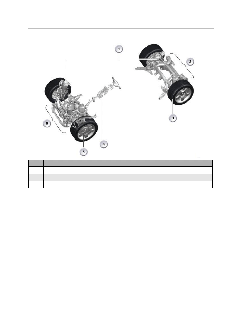
1
Spring/damper
4
Steering
2
Rear axle
5
Brakes
3
Wheels/tires
6
Front axle

Dampers/Suspension
In the E70, the range of spring/damper units extends from steel springs with conventional
dampers through to the new vertical dynamic control (VDC) that, in addition to the elec-
tronically controlled dampers, also allows a combination of a 1-axis air spring on the rear
axle. This 1-axis air spring is compulsory on vehicles with 8-cylinder engines and/or a
third row of seats.
Brakes
The brake system installed on the E70 is a further-developed high performance brake
system with newly adapted dimensions for the E70. The service brake is based on the
conventional design while in contrast to the E53 the parking brake features an
electro-mechanical parking brake system (EMF).
Steering
The E70 is available with two steering system variants:
• Hydraulic power steering
• Active steering (AL)
Both steering systems are adapted to the diverse and varied possible applications of the
E70 and the active steering is used for the first time in an all-wheel drive vehicle.
Wheels and Tires
The E70 is the first all-wheel drive vehicle (X-family) that is equipped with a run flat safety
package as standard.
12
E70 Chassis Dynamics
General
The chassis and suspension system is divided into the following main components:
• Front axle
• Rear axle
• Damping/suspension
• Brakes
• Steering
• Wheels/tires
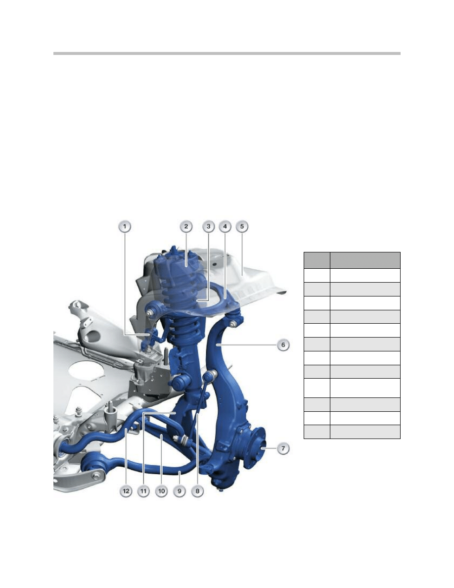
Front Axle
13
E70 Chassis Dynamics
Index
Explanation
1
Ride-height sensor
2
Mount
3
Spring strut
4
A-arm, top
5
Spring strut support
6
Swivel bearing
7
Wheel bearing
8
Stabilizer link
9
Tension strut with
hydraulic mount
10
Control arm, bottom
11
Spring strut fork
12
Anti-roll bar

The introduction of a second control arm level for wheel control, which is arranged above
the wheel, results in additional degrees of freedom for the kinematics of the front axle as
well as for the suspension/damping compared to other designs such as a McPherson
strut axle.
Components with special materials (see graphic on previous page):
• The forged aluminum swivel bearing (6) with the 3rd generation wheel bearing (7)
Semi-trailing arm connected via steel bushes/tapered screw connection to the swivel
bearing. Attention: Refer to special repair instructions!
• The A-arm at the top (4) is made from forged aluminum and the cylindrical joint pin
is clamped in the swivel bearing (6).
• Tension strut with hydraulic mount (9) and bottom control arm (10) are forged steel
components while the bottom control arm bears the spring strut (3) by means of the
cast steel spring strut fork (11).
• The front axle subframe is a welded steel structure with an aluminum thrust panel for
maximum lateral stiffness with service openings.
14
E70 Chassis Dynamics
Virtual Pivot Point
The steering pivot axis of the wheel suspension is now formed by a joint at the top A-arm
and the virtual pivot point of the lower arm level as known from the spring strut or
McPherson axle.
15
E70 Chassis Dynamics

The steering pivot axis is therefore freely selectable and can be positioned such as to
produce a small disturbing force lever arm with sufficient weight recoil. This disturbing
force lever arm is decisive for transmitting the irregularities on the road surface to the
steering wheel. The upper and lower arm level now move simultaneously in response to
wheel lift so as to swivel the wheel during spring deflection in such a way that the
negative camber with respect to the road is not reduced as much as on a McPherson
strut suspension setup.
Since the two control arm levels undertake the wheel control, the damper is no longer
subjected to transverse forces. This makes it possible to do without a roller bearing
assembly as the strut mount on the spring strut support. Instead of this conventional
roller bearing, two PUR discs (hybrid bearing) are fitted above and below the spring strut
mount.
Due to the substantially lower friction, the damper can respond more sensitively to
unevenness of the road surface. Due to the lack of transverse forces, the piston rod can
be made thinner, resulting in a similar displacement volume in the push and pull direction
of the damper. This serves to improve the design layout of the damper and is the
pre-requisite for the innovative damper control system - vertical dynamic control (VDC).
By connecting the anti-roll bar via the stabilizer link to the swivel bearing, the torsion in
response to body roll motion is equivalent to the total wheel lift from the inside to the
outside of the curve (in other suspension setups, the anti-roll bars are connected to a
control arm and therefore achieve only a fraction of the torsion angle). Despite being
highly effective, this high degree of torsion allows for the anti-roll bar to be made relatively
thin which has a favorable effect on driving comfort and dynamics as well as saving
weight.
Cast Aluminum Spring Support (body side)
The spring support on the E53 was not yet made of aluminum but rather from a conven-
tional sheet metal shell construction. On the E70, a cast aluminum spring support is
used for the first time in the front end of the X-Series with the following advantages:
• Reduced weight through intelligent lightweight construction
• Improved driving dynamics thanks to higher degree of stiffness
• Less components therefore reduced manufacturing expenditure
The cast aluminum spring support takes up the forces from the chassis and suspension
and directs them into the car body. Both the spring strut as well as the upper control arm
are secured to the cast spring support. The component must exhibit a high degree of
stiffness for this purpose. This is achieved by optimum material distribution by ensuring
material is only accumulated where necessary.
16
E70 Chassis Dynamics

The spring support therefore represents an important contribution to controlling driving
characteristics as it takes up both static and dynamic wheel forces. Since, with the cast
construction, it is possible to integrate many individual functions and components in one
single component, compared to the conventional shell construction, this setup is distinct-
ly more compact while making a significant contribution to reducing weight.
• The cast aluminum lightweight construction reduces the weight by approximately
50% compared to the conventional sheet steel construction.
• More useful package space compared to conventional sheet steel construction -
80 mm shorter front end
• Function-compliant design with specific local stiffening points adding to lightweight
construction
• Integration of various brackets for mounting units etc. in the cast aluminum spring
support with add-on parts
The cast aluminum spring support is connected to the neighboring steel components
(e.g. engine support) by means of a rivet-adhesion structure. The structure is of lower
weight while making it possible to reduce the number of parts (no additional sheet metal
brackets). Nevertheless, the vehicle body is more stable and torsionally rigid while
increasing local stiffness. This design arrangement has a positive effect on improved
driving dynamics.
17
E70 Chassis Dynamics
Front axle data
E70
Wheel
R18 8.5J X 18 EH2 + IS46
Tires
255/55 R18
Rim offset (mm)
46
Tire radius (mm)
338
Wheelbase (mm)
2933
Track width (mm)
1644
Camber
-0° 20’ ±20’
Camber difference
0° ±30’
Total toe-in
10’ ±6’
Wheel axle angle
0° ±4’
Kingpin offset (mm)
-8.4
Toe-out difference angle
2.1° ±30’
Caster angle
7° 48’ ±30’
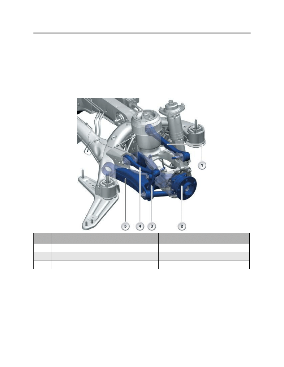
Rear Axle
The integral IV rear axle fitted in the E70 fulfills the primary function of the running gear
and wheel control in a unique way while making a significant contribution to driving
dynamics.
Safety functions are defined by the superior vehicle control characteristics. Effective
de-coupling of the road and drive train guarantees outstanding levels of acoustic and
vibration comfort.
The principle of the integral IV rear axle makes it possible to resolve the conflict between
driving dynamics and comfort. The dynamic and drive forces applied through the wheel
contact point into the wheel suspension are taken up by the wheel carrier, rear axle carrier
and four control arms. The design layout reduces the flexible pulling action in the wheel
carrier and therefore enables lengthways damping of the wheel control, which is
important for rolling comfort, by means of soft front link brackets on the rear axle carrier.
18
E70 Chassis Dynamics
Index
Explanation
Index
Explanation
1
Control arm
4
Upper radius arm
2
Wheel carrier
5
Swinging arm
3
Integral link

Thanks to the position of the spring on the wheel carrier, it is no longer necessary to
support the weight of the vehicle on the rubber mounts on the rear axle carrier.
The optimum lengthways damping and the favorable spring position facilitate effective
isolation of rolling and drive noise while significantly contributing to the refined smooth
and quiet vehicle running characteristics.
The rear axle of the E53 has undergone consistent further development for the E70 and
adapted to the requirements of the larger dimensions, higher overall weight, increased
power/torque, the BMW run flat safety system and the demanding objectives in terms of
driving dynamics and comfort. The main criteria that governed the selection of materials
included component weight, production process (cold forming, casting properties, weld-
ing properties), strength and deformation characteristics as well as corrosion resistance.
The resulting advantages include:
Outstanding driving dynamics, further increased compared to the E53, without compro-
mising comfort and driving safety.
• Distinctly larger and more functional load area by increasing the effective load width
and depth.
• Level control (1-axis air suspension) ensures constant ride-height and driving charac-
teristics irrespective of the vehicle load.
Rear axle data:
19
E70 Chassis Dynamics
Rear axle data
E70
Wheel
R18 8.5J X 18 EH2 + IS46
Tires
255/55 R18
Rim offset (mm)
46
Tire radius (mm)
338
Wheelbase (mm)
2933
Track width (mm)
1650
Camber
-1° 30’ ±15’
Camber difference
0° ±30’
Total toe-in
10’ ±6’
Wheel axle angle
0° ±4’

Damping/Suspension
The E70 is equipped with steel springs and conventional dampers as the standard
suspension setup. In addition, the following combinations are available:
• Standard suspension with sport suspension setup
• Standard suspension with 1-axis air spring
• Adaptive drive with steel springs and VDC dampers
• Adaptive drive with 2 steel springs and 1-axis air spring and VDC dampers
Brakes
In terms of function, an optimized high performance brake system is used on the E70.
Floating brake calipers are fitted on the front and rear axle. The brake system in the E70
features the known brake wear monitoring system for the CBS indicator.
20
E70 Chassis Dynamics
Front axle
N52B30 US+LA
N62B48 US+LA
Brake caliper housing
GGG
GGG
Brake caliper/piston diameter [mm]
60
60
Brake disc thickness [mm]
30
30
Brake disc diameter [mm]
332
348
Size
17’’
18’’
Rear axle
N52B30 US+LA
N62B48 US+LA
Brake caliper housing
AL
AL
Brake caliper/piston diameter [mm]
44
44
Brake disc thickness [mm]
20
24
Brake disc diameter [mm]
320
345
Size
17’’
18’’
Parking brake
Duo-Servo 185x30 (EMF)
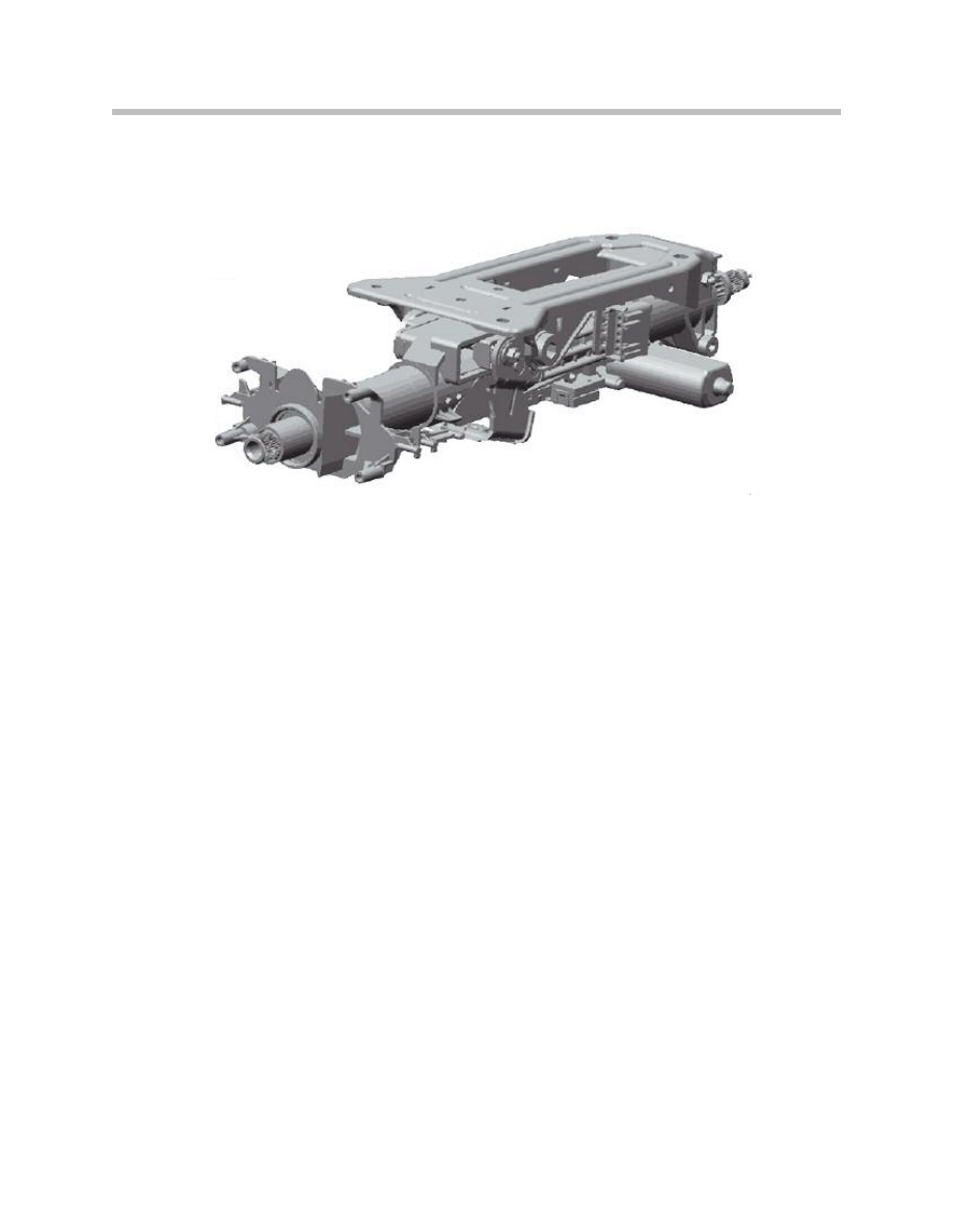
Steering
The E70 is available with an electrically adjustable steering column as standard equipment.
Adjustment range of manual steering column:
• Vertical +/-25 mm
• Horizontal +/-20 mm
Adjustment range of electrical steering column:
• Vertical +/-25 mm
• Horizontal +/-20 mm
A special feature of the electrically adjustable column is that only one electric motor is
required for the height and tilt adjustment and this motor is connected to a special gear
mechanism for both adjustment axes.
21
E70 Chassis Dynamics
A special feature of the adjustable steering column on the E70 is the innovative crash
system consisting of a crash adapter and crash tube. In the event of a crash, the impact
energy is progressively reduced for the driver by the crash tube breaking open and
deforming, thus providing the advantage of reduced stress on the occupants in the event
of a crash (integral part of the 5-star philosophy at BMW). In addition, the lower and cen-
ter steering shaft collapses during the crash thus preventing penetration of the steering
column into the passenger compartment.
Advantages of this new steering column:
• Low risk of injury in the event of a crash
• Thanks to its versatile adjustment options, the steering column provides excellent
ergonomic positioning for the driver.
Wheels and Tires
For the first time, an X-vehicle is equipped as standard with the run flat safety system.
Tyre damage and tire failure are among the most feared driving experiences.
The BMW run flat safety system:
• Warns the driver in good time of imminent tire pressure loss so that counter-mea-
sure can be taken.
• Allows the journey to be continued for a defined distance even in the event of
complete loss of tire pressure.
• Keeps the tire safely on the rim even in the event of sudden tire pressure loss at
high speed.
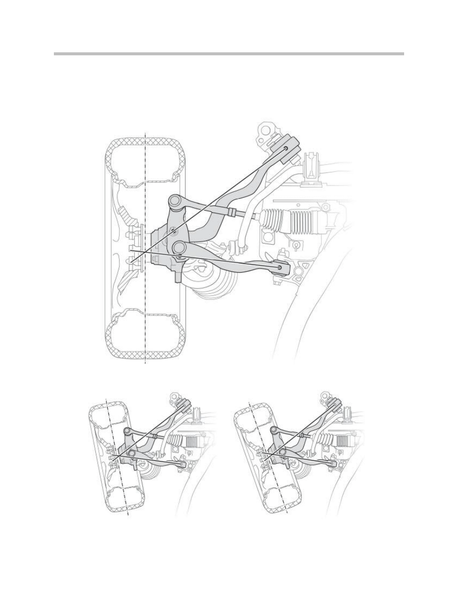
22
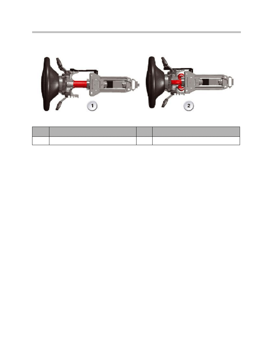
E70 Chassis Dynamics
Index
Explanation
Index
Explanation
1
Normal position ( 0-mm)
5
Crash position (80-mm compressed)

The system consisting of the run flat tires (RSC), rims with extended hump (EH2+) con-
tour and the electronic monitoring system (TPMS), renders a spare wheel or space-saver
wheel, breakdown kit or vehicle jack unnecessary and this creates more storage space in
the luggage compartment while also saving weight.
Extended Hump Rims (EH2+)
The specially shaped rim humps ensure that the RSC tire cannot detach from the rim
even in the case of sudden tire pressure loss. This means substantially greater safety
particularly when driving at high speed and on winding roads.
Tire Failure Indicator RPA
The electronic monitoring system RPA monitors the tire pressure by constantly
comparing the wheel speeds (dynamic rolling circumference). A warning lamp informs
the driver of any irregularities that occur due to the loss of tire pressure. The system
triggers a warning as from a vehicle speed of 25 km/h and at a pressure drop of more
than 30%.
The RPA system is designed to signal a sudden and excessive loss of pressure and does
not exempt the driver from regularly checking the tire pressure. After changing the tire
pressure or after changing a tire, the RPA must be re-initialized in order to restore the
target values with the correct tire pressure.
The entire safety package consists of three components:
• RSC tires with emergency running properties
• Extended hump rims (EH2+)
• Tire Pressure Monitoring System (TPMS).
RSC tires with emergency running properties
With its reinforced side walls, additional strip inserts and heat-resistant rubber mixtures,
even when completely depressurized, the "self-supporting tire" makes it possible to
continue the journey for a limited distance at a maximum speed of 80 km/h. This means
each tire is also its own spare wheel.
The maximum range after complete tire pressure loss is:
• approximately 250 km at low vehicle load
• approximately 150 km at medium vehicle load
• approximately 50 km at high vehicle load
In the case of slow pressure loss, i.e. representative of approximately 80% of all tire failure
cases, the remaining range as from the RPA warning is approximately 2000 km. ABS,
ASC and DSC remain fully operational even in the event of complete tire pressure loss.
When driving with a run flat tire with no pressure, the optionally available adaptive drive
system automatically distributes the vehicle weight over the remaining wheels so as to
relieve the load on the depressurized tire with the aim of achieving the highest possible
range for continued operation.
23
E70 Chassis Dynamics
Document Outline
- Main Menu
- E70 Introduction
- E70 Glovebox
- E70 Powertrain
- E70 Gasoline Engines
- E70 Transmissions
- E70 Voltage Supply and Bus Systems
- E70 Car Access System 3
- E70 Energy Management
- E70 Chassis Dynamics
- E70 Lateral Dynamics Systems
- E70 Vertical Dynamics Systems
- E70 Longitudinal Dynamics Systems
- E70 Central Locking
- E70 Power Windows
- E70 Comfort Access
- E70 Wipe/Wash System
- E70 Panorama Glass Sunroof
- E70 Seats
- E70 Automatic Tailgate
- E70 Steering Column Switch Cluster
- E70 Exterior Lighting
- E70 Interior Lighting
- E70 Adaptive Headlight System
- E70 Park Distance Control
- E70 Rear-view Camera
- E70 Anti-Theft Alarm System
- E70 Outside Mirrors
- E70 Displays Indicators and Controls
- E70 Head-up Display
- E70 Information and Communication
- E70 Audio Systems
- E70 Rear Seat Entertainment
- E70 Climate Control Systems
- E70 Passive Safety Systems
Wyszukiwarka
Podobne podstrony:
04b E70 Lateral Dynamics Systems
02b E85 Chassis Dynamics 03 21 03
06 E83 Chassis Dynamics
06 E85 Chassis Dynamics
01 Introduction to Chassis Dynamics
04d E70 Longitudinal Dynamics Systems
05 E60 Chassis Dynamics
Dynamika1
Techniki wywierania wplywu oparte na dynamice interakcji
Analiza dynamiczna chodu w fazie podporu
dynamika bryly sztywnej(1)
Kurs 03 Dynamika
Parzuchowski, Purek ON THE DYNAMIC
04a Różnice CerapurSmart Comfort
Automatyka dynamiakPAOo 2
philips chassis l6 1
więcej podobnych podstron