Volkswagen
1
industrial engine
Set-up Instructions
AFD
05.97
K-VSI
Industrial Sales
04.11.98
1961
Set-up Instructions
for 1.9-litre TDI - industrial engine AFD
using the
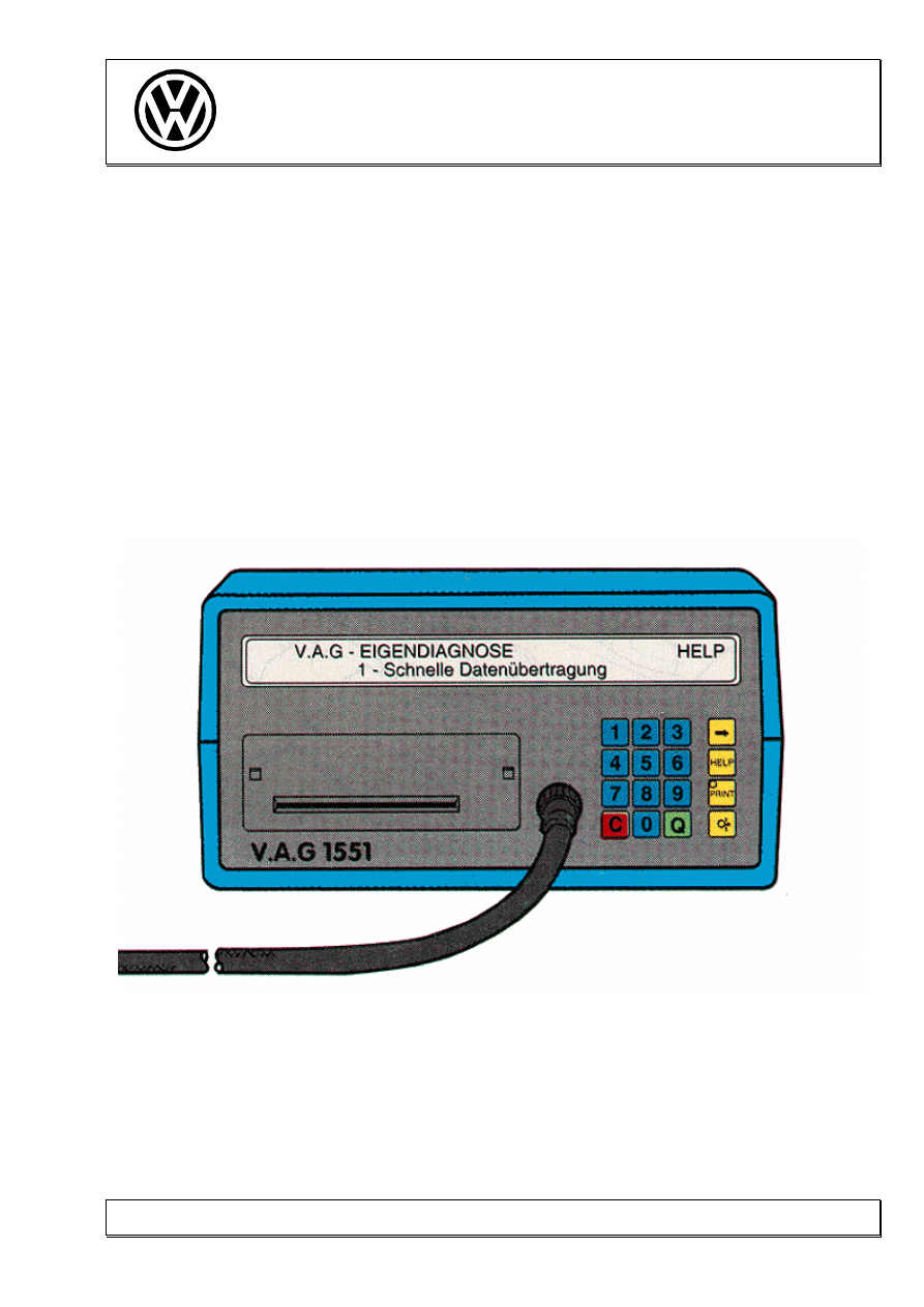
V.A.G-1551
1.9-litre TDI / MSA 15
from 10.96
As at: 04.11.1998
Version: 1.2

Volkswagen
2
industrial engine
Set-up Instructions
AFD
05.97
K-VSI
Industrial Sales
04.11.98
1961
Contents: Page
1.
Notes on initial operation
3
2.
Functions of the diagnosis tester 1551
4
2.1 Explanation of functions 01 and 07 of the diagnosis tester
5
3.
Connecting the control unit to the diagnosis tester 1551
7
4.
Examining the fault memory
8
5. Temperature measurements on a cold engine
9
6.
Examining basic settings
10
7.
Control element test
12
8.
Examination of vehicle with AFD engine at idling speed
15
8.1 Decimal representation (10-digit block)
16
8.2 Normed representation
16
9.
Examination of vehicle with AFD engine at full load
20

Volkswagen
3
industrial engine
Set-up Instructions
AFD
05.97
K-VSI
Industrial Sales
04.11.98
1961
1. Notes on initial operation
•
These instructions are intended for the "examination of a 1.9-litre TDI - industrial engine
AFD" with the MSA 15control unit.
•
Example:
•
Set-up must be carried out with the switch in the "drive operation" position.
•
For the "examination with engine running", the vehicle should have a coolant temperature
of at least 60°C. All electrical consumers must be switched off.
•
Texts appearing in the display of the V.A.G 1552 / 1551, are reproduced in a frame.
Entries made on the keyboard are given underneath ( in this example "01").
e.g.
Rapid data transfer
HELP
Enter address word XX
01

Volkswagen
4
industrial engine
Set-up Instructions
AFD
05.97
K-VSI
Industrial Sales
04.11.98
1961
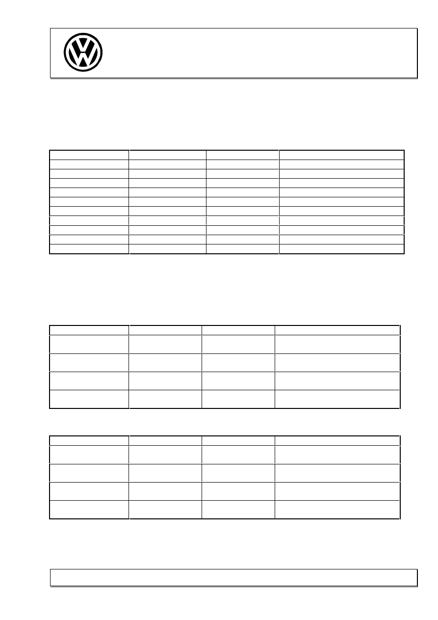
2. Functions of the diagnosis tester 1551
The following functions are available under the address word 01 - engine electronics:
No. Function
Page
01:
Obtain control unit version
5
02:
Read fault memory
8
03:
Control element diagnosis
12
04:
Basic setting
10
05:
Erase fault memory
06:
End output
07:
Code control unit
6
08:
Read measuring value block
9
09:
Read individual measuring values

Volkswagen
5
industrial engine
Set-up Instructions
AFD
05.97
K-VSI
Industrial Sales
04.11.98
1961
2.1 Explanation of functions 01 and 07 of the diagnosis tester
Function 01: Obtain control unit version.
−
On delivery of the standard ECU 028 906 021 CS, the zero-th of eight
possible data blocks is activated. A new ECU must be coded prior to its initial
operation.
−
The control unit currently contains two different data blocks, each indicated by
a five-digit code, which have been certified by the TÜV:
Code 00000 = data block 1
Code 00001 = data block 1
Code 00002 = data block 2
Code 00003 = data block 1
Code 00004 = data block 1
Code 00005 = data block 1
Code 00006 = data block 1
Code 00007 = data block 1
Code 00008 = data block 1
−
In other words, all codes not currently allocated a separate data block
automatically contain data block 00001. However, if the control unit is
activated with a code which has not yet been approved, the message "Control
unit incorrectly coded" will appear when the fault memory is read.
−
The identification of the workshop code (WSC) is always 00000 on delivery
from production. Only after the IMO customer has for example changed the
ECU coding with the V.A.G tester will his own WSC, ass allocated to him by
VW, appear. This acts as a "fingerprint", making it possible to trace any
change in ECU coding.

Volkswagen
6
industrial engine
Set-up Instructions
AFD
05.97
K-VSI
Industrial Sales
04.11.98
1961
Function 07: Coding control unit
−
To carry out this function, the IMO customer must input his own operator
number into the V.A.G tester and inform his responsible distributor/importer of
this. Without this operator number it is not possible to change the data block.
−
After changing to a new data block, e.g. code 00002, this will be displayed
under function 01 "Obtain control unit version". IMPORTANT !
−
The new data block is not activated until the ECU is reset to the new data
block by switching off the ignition for at least 10 seconds. Until this is done,
the originally data block remains active.
Volkswagen
7
industrial engine
Set-up Instructions
AFD
05.97
K-VSI
Industrial Sales
04.11.98
1961
3. Connecting the control unit to the diagnosis tester 1551
Procedure for connecting up the TDI engine control unit MSA15.
Turn the ignition key to the "ignition on" position.
V.A.G - Self-diagnosis
HELP
1- Rapid data transfer
(display flashes)
1
Rapid data transfer
HELP
Input address word XX
01
Rapid data transfer
01-Engine electronics
Q
Please wait
Industrial engine control unit
028 906 021CS
1.9 ltr. R4
IMO
G00SG
0818
Ð
Coding: 00000
WSC 00000
Ð
Volkswagen
8
industrial engine
Set-up Instructions
AFD
05.97
K-VSI
Industrial Sales
04.11.98
1961
4. Examining fault memory
Rapid data transfer
HELP
Select function XX
02
Rapid data transfer
Q
Interrogate fault memory
Q
No fault recognised
*
Ð
Ð
*
On initial operation, the message "Control unit incorrectly coded" appears. The ECU
must be re-coded (function 07)
Volkswagen
9
industrial engine
Set-up Instructions
AFD
05.97
K-VSI
Industrial Sales
04.11.98
1961
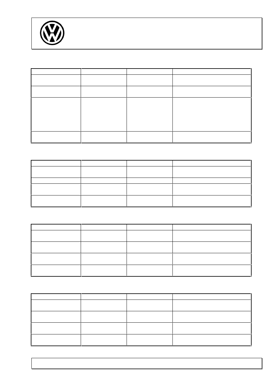
5. Temperature measurements with a cold engine
Precondition for this test is that the vehicle has been left standing over night and the engine
has not beet started. The temperature sensors for coolant, intake manifold and fuel must all
give roughly the same reading.
Rapid data transfer
HELP
Select function XX
08
Rapid data transfer
Q
08 Read measuring value block
Q
Read measuring value block
Enter display group number XXX
Display group number
007
Q
Display group number 07: Temperatures
cold, standing engine
Description
Specification
VAG 1551 reading
Remarks
Fuel
[°C]
-20...+20
Reserve
Intake air
temperature [°C]
-20...+20
Coolant
[°C]
-20...+20
Important:
The deviation within the measured temperatures must not exceed 5°C.
Volkswagen
10
industrial engine
Set-up Instructions
AFD
05.97
K-VSI
Industrial Sales
04.11.98
1961
6. Examining basic setting
The engine control unit outputs a fixed specification value during the basic setting. This
value does not correspond to the idling speed value. A comparison of specification and
actual values gives information of the function of the corresponding regulatory circuits.
Engine running at idling speed
Rapid data transfer
HELP
Select function XX
04
Rapid data transfer
Q
04 Basic setting
Q
Basic setting
Enter display group number XXX
000
Q
Volkswagen
11
industrial engine
Set-up Instructions
AFD
05.97
K-VSI
Industrial Sales
04.11.98
1961
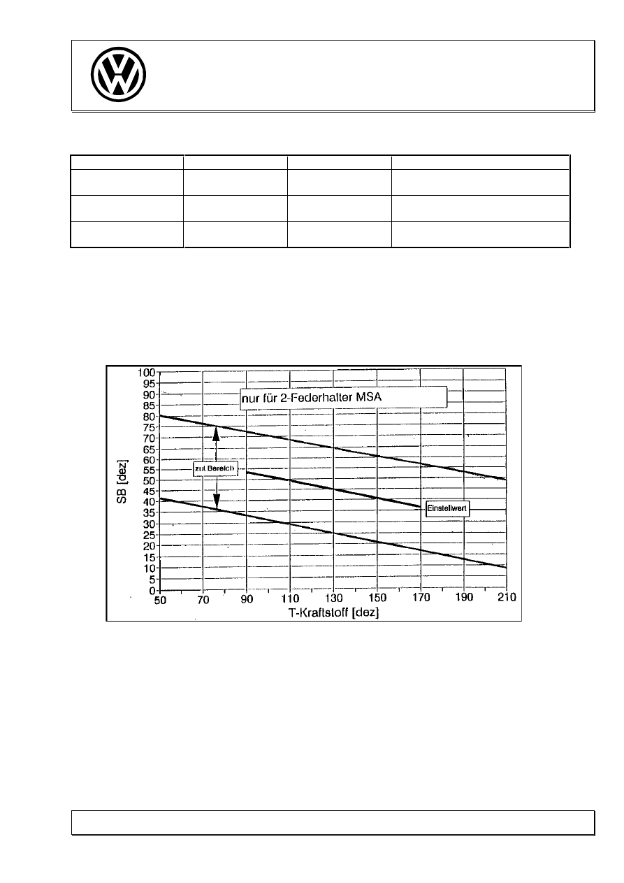
Channel 00: Commencement of injection
Basic setting
Description
Specification
VAG 1551 reading
Remarks
Comm. of injection
[dec.]
see diagram
2nd decimal value from the left
Fuel temperature
[dec.]
see diagram
9th decimal value from the left
The readings for commencement of injection (SB) and fuel temperature (T-Kraftstoff) must
correlate with the following diagram.
15

Volkswagen
12
industrial engine
Set-up Instructions
AFD
05.97
K-VSI
Industrial Sales
04.11.98
1961
7. Control element test
This examination test individual control elements. Each control element is pulsed for a
period of 30 seconds, i.e. it is moved alternately between its extreme positions.
The evaluation of control elements should be entered in the table at the end of this section,
either as "OK" or "not OK". Measured values are required only for the exhaust gas
recirculation and the commencement of injection. To do this, it is necessary to actuate the
control elements N18 (exhaust gas recirculation valve) and N108 (commencement of
injection valve) and then to leave the control element test with "Cancel". Proceeding in this
manner effectively "pulses" the exhaust gas recirculation and commencement of injection
valves, allowing the extreme values for exhaust gas recirculation and commencement of
injection to be measured in Channel 003 and 004 respectively of measuring value block.
Rapid data transfer
HELP
Select function XX
03
Rapid data transfer
Q
03 Control element test
Q
Commencement of injection valve N108
Ð
Ð
The commencement of injection valve does not have to be evaluated as the basic setting
contains all the necessary information.
Volkswagen
13
industrial engine
Set-up Instructions
AFD
05.97
K-VSI
Industrial Sales
04.11.98
1961
Exhaust gas recirculation valve N18
Ð
Channel 03: Exhaust gas recirculation
Control element test
Description
Specification
VAG 1551 reading
Remarks
Engine speed
[1/min]
861...945
EGR specified
[mg/stroke]
0 ... 180
EGR actual (EGR on)
[mg/stroke]
230...320
Difference between the specified
and actual value is possible on the
AFD
EGR actual (EGR off)
[mg/stroke]
360...480
Difference between the specified
and actual value is possible on the
AFD
on-off ratio (EGR on)
[%]
94
on-off ratio (EGR off)
[%]
4
Air conditioner compressor engagement
Switching on the air conditioner compressor, if available, must be visually and audibly
recognisable (not relevant for the AFD engine).
Ð
Fuel cut-off valve (ELAB)
The engine must stop.
Ð
Solenoid valve for charge pressure limitation N75
Grasp the charge pressure control element. The relay must be felt to switch.
Ð
Glow plug relay J52
Switch on interior lighting! A difference in lighting intensity (bright/dim) must be noticeable.
If the glow plug relay can be heard to switch, this control element is also OK.
Ð
Volkswagen
14
industrial engine
Set-up Instructions
AFD
05.97
K-VSI
Industrial Sales
04.11.98
1961
Glow period warning lamp K29
The preglow lamp must light up rhythmically.
Ð
Relay for lower heater output J359
The control relay must be audible (not relevant for the AFD engine).
Ð
Relay for higher heater output J360
The control relay must be audible (not relevant for the AFD engine).
Control elements
Control element
not OK
OK
Remarks
Air conditioner cut-off:
check that compressor is running
only if fitted
ELAB:
engine must stop
Charge pressure valve:
feel CPR by hand
Glow plug relay:
check interior lighting intensity
(bright/dim)
(preglow lamp does not light up)
Warning lamp:
preglow lamp must flash
Relay for lower heater output:
control relay must be heard to
switch
not relevant for the AFD engine
Volkswagen
15
industrial engine
Set-up Instructions
AFD
05.97
K-VSI
Industrial Sales
04.11.98
1961
8. Examination of vehicle with the AFD engine at idling speed
Sensor values, specifications and switch positions are registered.
Start the engine now!
Rapid data transfer
HELP
Select function XX
08
Rapid data transfer
Q
08 Read measuring value block
Q
Read measuring value block
Enter display group number XXX
Display group number
000
Q
Volkswagen
16
industrial engine
Set-up Instructions
AFD
05.97
K-VSI
Industrial Sales
04.11.98
1961
8.1 Decimal representation (10-digit block)
Display group number 000: 10-digit block
Idle
Description
Specification
VAG 1551 reading
Remarks
Engine speed
41...45
Comm. of injection
50 ... 125
Throttle position
0
Injection quantity
15 ... 45
Charge pressure
82 ...112
Atmospheric pressure
181 ... 242
Coolant temperature
35 ...167
Intake air temperature
51...182
Fuel temperature
91... 201
Air mass
69 ...128
8.2 Normed Representation
Display group number 001: Quantity adjustment
Idle
Description
Specification
VAG 1551 reading
Remarks
Engine speed
[rpm]
861... 945
Injection quantity
[mg/stroke]
3 ... 9
Voltage
[V]
1.50 ... 1.95
Coolant temperature
[°C]
20 ...110
Display group number 002: Idling speed
Idle
Description
Specification
VAG 1551 reading
Remarks
Engine speed
[rpm]
861 ... 945
Throttle position
[%]
0
Switch positions
010
Meaning of bits (from the left):
idle boost, idle switch, a/c
Coolant temperature
[°C]
20 ...110

Volkswagen
17
industrial engine
Set-up Instructions
AFD
05.97
K-VSI
Industrial Sales
04.11.98
1961
Display group number 003: Exhaust gas recirculation
Idle
Description
Specification
VAG 1551 reading
Remarks
Engine speed
[rpm]
861 ... 945
EGR specified
[mg/stroke]
0 ... 180
EGR actual
[mg/stroke]
230 ... 420
Difference between specified and
actual value is possible on the AFD
on-off ratio
[%]
40 ... 60
Display group number 004: Commencement of injection (SB)
Idle
Description
Specification
VAG 1551 reading
Remarks
Engine speed
[rpm]
861 ... 945
SB specified
[° crankshaft]
1 ... 7 before TDC
SB actual
[° crankshaft]
1 ... 7 before TDC
on-off ratio
[%]
2 ... 95
Display group number 005: Starting quantity
Idle
Description
Specification
VAG 1551 reading
Remarks
Engine speed
[rpm]
861 ... 945
Starting quantity
[mg/stroke]
15 ... 30
SB actual
[° crankshaft]
1 ... 7 before TDC
Coolant temperature
[°C]
>80
The coolant temperature should be
above 80°C for the measurement
Display group number 006: Switch positions
in drive mode
Idle
Description
Specification
VAG 1551 reading
Remarks
Road speed
[km/h]
50 ... 70
Switches
1 0 0
Meaning of bits (from the left):
clutch, red. brake, brake
Speed governor status
Speed governor status
(OLDA channel 75)
0
0 = activated in ECU
255 = not activated in ECU
Volkswagen
18
industrial engine
Set-up Instructions
AFD
05.97
K-VSI
Industrial Sales
04.11.98
1961
Display group number 006: Switch positions
in governed mode
Idle
Description
Specification
VAG 1551 reading
Remarks
Road speed
[km/h]
50 ... 70
Switches
0 0 0
Meaning of bits (from the left):
clutch, red. brake, brake
Speed governor status gov. off:
000 000
gov. on:
000 001
gov. WA: 001 001
tip up:
000 101
idling speed
switch:
000 011
Governor must be switched on.
Only in governed outside operation
Speed governor status
(OLDA channel 75)
0
0 = activated in ECU
255 = not activated in ECU
Display group number 007: Temperatures
Idle
Description
Specification
VAG 1551 reading
Remarks
Fuel temperature
[°C]
20 ... 80
Reserve
Intake air temperature
[°C]
10 ... 100
Coolant temperature
[°C]
20 ... 110
Display group number 010: Air readings
Idle
Description
Specification
VAG 1551 reading
Remarks
Air mass
[mg/Hub]
230 ... 420
Atmospheric pressure
[mbar]
900 ... 1200
Charge pressure
[mbar]
900 ... 1200
Throttle position
[%]
0
Display group number 011: Charge control
Idle
Description
Specification
VAG 1551 reading
Remarks
Engine speed
[rpm]
861 ... 945
Specified pressure
[mbar]
900 ... 1200
Actual pressure
[mbar]
900 ... 1200
on-off ratio
[%]
5 ... 95
Volkswagen
19
industrial engine
Set-up Instructions
AFD
05.97
K-VSI
Industrial Sales
04.11.98
1961
Display group number 012: Preglow
Idle
Description
Specification
VAG 1551 reading
Remarks
Glow status
11111111
glow off: 11111111
preglow: 00010000
start gl.: 01110000
intermed. gl: 11110000
after gl.: 10110000
Startbergl
.: 00110000
Preglow period
0
Battery voltage
[V]
13.5 ... 14.5
Coolant temperature
[°C]
20 ... 110
The coolant temperature should be
above 80°C for the measurement
Display group number 013: Engine running control
Idle
Description
Specification
VAG 1551 reading
Remarks
Deviation cyl. 4
[mg/stroke]
-2 ...+2
Deviation cyl. 2
[mg/stroke]
-2 ...+2
Deviation cyl. 1
[mg/stroke]
-2 ...+2
Current
reserve
Volkswagen
20
industrial engine
Set-up Instructions
AFD
05.97
K-VSI
Industrial Sales
04.11.98
1961
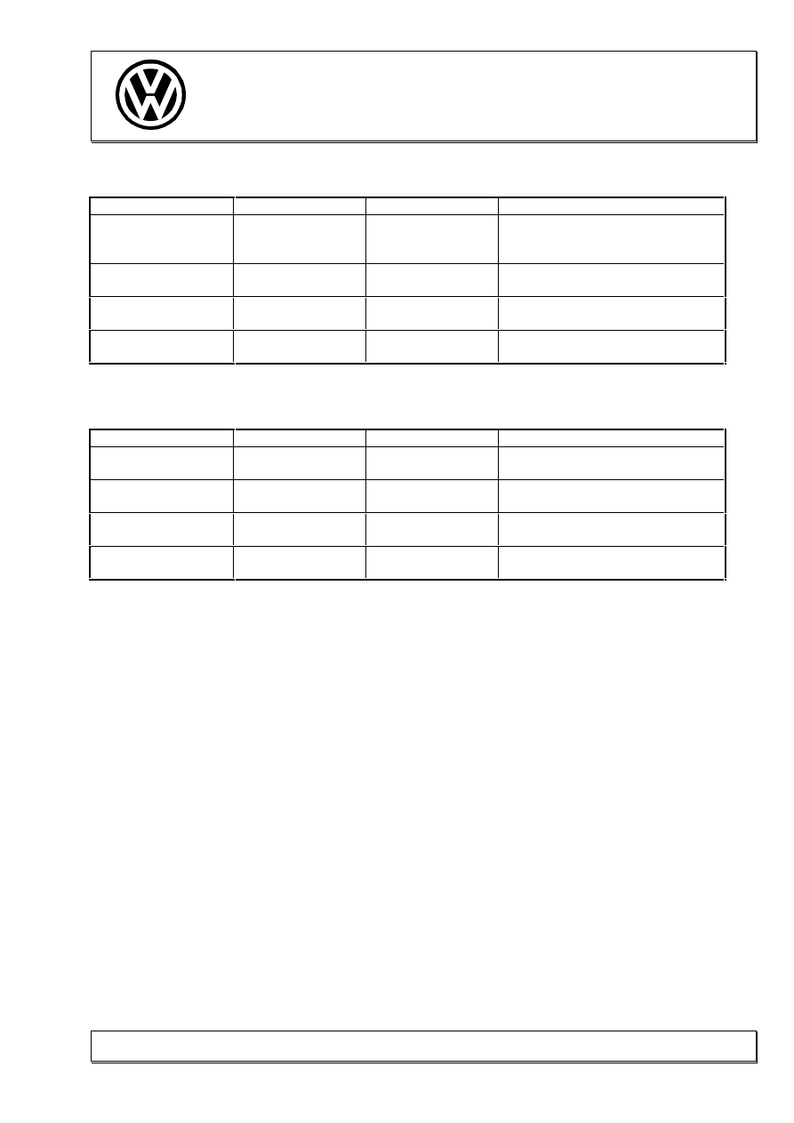
9. Examination of vehicle with the AFD engine under full load
This examination is to be carried out with the throttle potentiometer at 100% and the vehicle
under full load. If possible, the measuring values should read off or printed out when an
engine speed of 2500 [rpm] is reached.
Rapid data transfer
HELP
Select function XX
08
Rapid data transfer
Q
08 Read measuring value block
Q
Read measuring value block
Enter display group number XXX
Enter display group number
001
Q
Display group number 001: Quantity adjustment
Full load
Description
Specification
VAG 1551 reading
Remarks
Engine speed
[rpm]
2500
Injection quantity
[mg/stroke]
25 ... 35
Voltage
[V]
2.8 ... 3.5
Coolant temperature
[°C]
> 80
Volkswagen
21
industrial engine
Set-up Instructions
AFD
05.97
K-VSI
Industrial Sales
04.11.98
1961
Display group number 003: Exhaust gas recirculation
Full load
Description
Specification
VAG 1551 reading
Remarks
Engine speed
[rpm]
2500 ... 3000
EGR specified
[mg/stroke]
850
EGR actual
[mg/stroke]
720 ... 850
on-off ratio
[%]
4
Display group number 004: Commencement of injection (SB)
Full load
Description
Specification
VAG 1551 reading
Remarks
Engine speed
[rpm]
2500 ... 3000
SB specified
[° crankshaft]
5 ... 12 before TDC
SB actual
[° crankshaft]
5 ... 12 before TDC
on-off ratio
[%]
65 ... 85
Display group number 010: Air readings
Full load
Description
Specification
VAG 1551 reading
Remarks
Air mass
[mg/Hub]
700 ... 760
Atmospheric pressure
[mbar]
900 ... 1200
Charge pressure
[mbar]
1650 ... 2000
Throttle position
[%]
100
Display group number 011: Charge control
Full load
Description
Specification
VAG 1551 reading
Remarks
Engine speed
[rpm]
2500
Specified pressure
[mbar]
1650 ... 1950
Actual pressure
[mbar]
1650 ... 2000
on-off ratio
[%]
20 ... 70
Wyszukiwarka
Podobne podstrony:
błedy VAG Przegląd usterek diagnostycznych
VAg Przegląd usterek diagnostycznych
V A G Diagnoza VAG s1
ALGORITMO DIAGNÓSTICO TERAPÉUTICO Y PREVENTIVO EN VARONES IN
[Audi A4 TDI, Turbo] Diagnozowanie silnika TDI, Turbo
DIAGNOSTYKA OBD EOBD OBD2 Opis VAG id 135086
DIAGNOSTYKA ODDECHOWA 3id 1551 ppt
GE Diagnostyka silnika 1,9 TDI
Diagnostico Metabolico Nutricional Lipidico Proteico en?s
2 TDI Tuning mit VAG COM
ABC Diagnozowania i Adaptacji VAG
ilexa Onboard Diagnostics VAG COM VolksWagen service indicator resetting
ADVANCED DIAGNOSTICS OBD Connector Location for VAG
więcej podobnych podstron