
Table of Contents
Subject
Page
Objectives of the Module . . . . . . . . . . . . . . . . . . . . . . . . . . . . . . . . . . . . .1
Purpose of the System . . . . . . . . . . . . . . . . . . . . . . . . . . . . . . . . . . . . . . .2
Components
- Air Routing . . . . . . . . . . . . . . . . . . . . . . . . . . . . . . . . . . . . . . . . . . . . . .6
- Throttle Valve . . . . . . . . . . . . . . . . . . . . . . . . . . . . . . . . . . . . . . . . . . . .7
- Intake Manifold . . . . . . . . . . . . . . . . . . . . . . . . . . . . . . . . . . . . . . . . . . .8
- Crankcase Venting System . . . . . . . . . . . . . . . . . . . . . . . . . . . . . . . . . .12
- Exhaust Manifold with Catalytic Converter . . . . . . . . . . . . . . . . . . . . . . .13
- Silencers . . . . . . . . . . . . . . . . . . . . . . . . . . . . . . . . . . . . . . . . . . . . . . .14
- Secondary Air System . . . . . . . . . . . . . . . . . . . . . . . . . . . . . . . . . . . . . 14
- Belt Drive . . . . . . . . . . . . . . . . . . . . . . . . . . . . . . . . . . . . . . . . . . . . . .16
- Alternator . . . . . . . . . . . . . . . . . . . . . . . . . . . . . . . . . . . . . . . . . . . . . . 17
- Air Conditioning Compressor . . . . . . . . . . . . . . . . . . . . . . . . . . . . . . . . 19
- Starter Motor . . . . . . . . . . . . . . . . . . . . . . . . . . . . . . . . . . . . . . . . . . . .19
- Power Steering Pump . . . . . . . . . . . . . . . . . . . . . . . . . . . . . . . . . . . . . 19
- Engine Covers . . . . . . . . . . . . . . . . . . . . . . . . . . . . . . . . . . . . . . . . . . 21
- Valve Gear . . . . . . . . . . . . . . . . . . . . . . . . . . . . . . . . . . . . . . . . . . . . . 22
- Valvetronic . . . . . . . . . . . . . . . . . . . . . . . . . . . . . . . . . . . . . . . . . . . . . 23
- Bi-VANOS . . . . . . . . . . . . . . . . . . . . . . . . . . . . . . . . . . . . . . . . . . . . . 29
- Vacuum Pump . . . . . . . . . . . . . . . . . . . . . . . . . . . . . . . . . . . . . . . . . . 34
- Chain Drive . . . . . . . . . . . . . . . . . . . . . . . . . . . . . . . . . . . . . . . . . . . . 35

Subject
Page
Components
- Water Pump . . . . . . . . . . . . . . . . . . . . . . . . . . . . . . . . . . . . . . . . . . . . 40
- Map-Controlled Thermostat. . . . . . . . . . . . . . . . . . . . . . . . . . . . . . . . . . 42
- Cooling Module . . . . . . . . . . . . . . . . . . . . . . . . . . . . . . . . . . . . . . . . . . .42
- Radiator . . . . . . . . . . . . . . . . . . . . . . . . . . . . . . . . . . . . . . . . . . . . . . . . 43
- Expansion Tank . . . . . . . . . . . . . . . . . . . . . . . . . . . . . . . . . . . . . . . . . . 43
- Transmission Oil/Water Heat Exchanger . . . . . . . . . . . . . . . . . . . . . . . . .44
- Electrically-Operated Fan . . . . . . . . . . . . . . . . . . . . . . . . . . . . . . . . . . . 44
- Viscous Coupling Fan . . . . . . . . . . . . . . . . . . . . . . . . . . . . . . . . . . . . . . 44
- Oil Sump . . . . . . . . . . . . . . . . . . . . . . . . . . . . . . . . . . . . . . . . . . . . . . . 45
- Crankcase . . . . . . . . . . . . . . . . . . . . . . . . . . . . . . . . . . . . . . . . . . . . . .45
- Crankshaft . . . . . . . . . . . . . . . . . . . . . . . . . . . . . . . . . . . . . . . . . . . . . .46
- Connecting Rods and Pistons . . . . . . . . . . . . . . . . . . . . . . . . . . . . . . . . 46
- Flywheel . . . . . . . . . . . . . . . . . . . . . . . . . . . . . . . . . . . . . . . . . . . . . . . . 47
- Vibration Damper . . . . . . . . . . . . . . . . . . . . . . . . . . . . . . . . . . . . . . . . . 47
- Oil Jets . . . . . . . . . . . . . . . . . . . . . . . . . . . . . . . . . . . . . . . . . . . . . . . . . 48
- Oil Check Valve . . . . . . . . . . . . . . . . . . . . . . . . . . . . . . . . . . . . . . . . . . 48
- Oil Pump . . . . . . . . . . . . . . . . . . . . . . . . . . . . . . . . . . . . . . . . . . . . . . . 49
- Oil Filter . . . . . . . . . . . . . . . . . . . . . . . . . . . . . . . . . . . . . . . . . . . . . . . 51
- Pressure Control . . . . . . . . . . . . . . . . . . . . . . . . . . . . . . . . . . . . . . . . . 51
- Technical Data . . . . . . . . . . . . . . . . . . . . . . . . . . . . . . . . . . . . . . . . . . . 52

1
N62 Engine
N62 ENGINE
Model: E65 - 745i / E66 - 745Li
Engine: N62B44
Production Date: 11/2001 - E65, 01/2002 - E66
Objectives of The Module
After Completing this module, you will be able to:
• Describe the two stage oil supply.
• Distinguish the difference between the left and right drive chain tensioning assem-
blies.
• Explain the Bi-VANOS operation.
• Understand the function of the Variable intake manifold.
• Explain the cooling circuit flow.
• List what chamber A and chamber B is used for in the Bi-VANOS system.
• Identify the Secondary air components.
• Explain how the initial VANOS position is retained when oil pressure is not present.
• List the proper drive belt removal procedure.
• Describe the throttle valve functions.
• Identify the N62B44 designation.
2
N62 Engine
N62 Engine
Purpose of The System
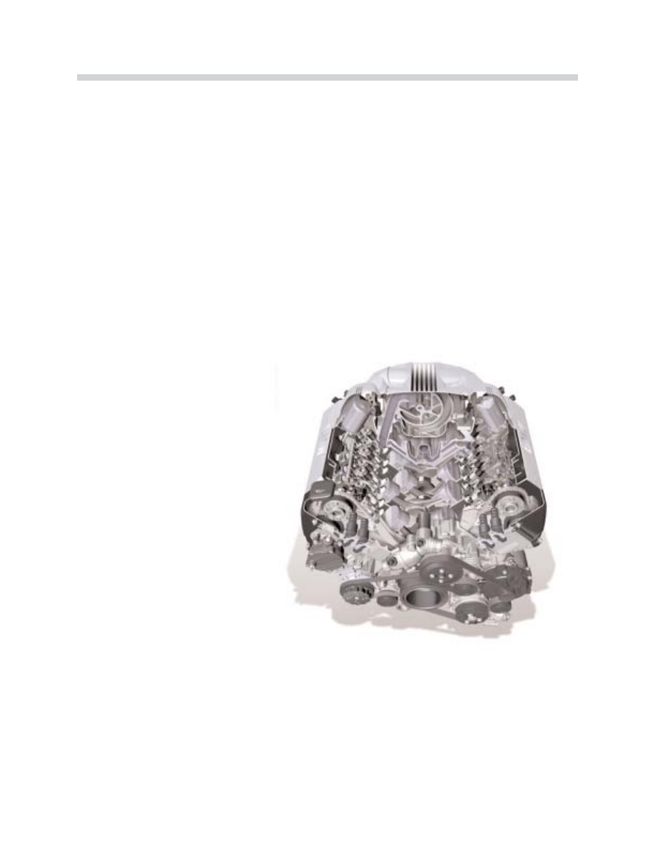
The N62B44 engine is a completely new development from the NG (New Generation) series
and is available as a B44 (4.4 liter).
The development objectives were:
• Reduction in fuel consumption
• Reduction in emissions
• Increased power
• Improved torque and torque curve
• Improved engine acoustics
The most important features of
the new N62 engine are:
• 8 cylinders in a 90º V configu-
ration
• 2 four-valve cylinder heads
• Light-alloy design
• Newly-developed variable
intake manifold
• Valvetronic system
In conjunction with the Variable Intake Manifold, the Valvetronic system adapts the intake
valve lift to ensure optimum cylinder filling. The throttle valve use is limited during engine
operation to maintain a constant intake manifold vacuum.
T
Th
he
e N
N6
62
2 iis
s tth
he
e b
be
es
stt e
en
ng
giin
ne
e iin
n iitts
s c
clla
as
ss
s.. A
Att tth
hiis
s ttiim
me
e tth
he
erre
e iis
s n
no
o o
otth
he
err e
en
ng
giin
ne
e o
on
n tth
he
e m
ma
arrk
ke
ett
w
wh
hiic
ch
h u
us
se
es
s c
co
om
mp
pa
arra
ab
blle
e tte
ec
ch
hn
no
ollo
og
gy
y..
To achieve these objectives, enhancements
were made in the following areas:
• Engine mechanicals
• Treatment of exhaust emissions
• Valve timing
• Engine management control
• Intake air flow
43-02-01

3
N62 Engine
Technical Data
E
En
ng
giin
ne
e
N
N6
62
2B
B4
44
4
Design
8 Cylinder V
V Angle
90°
Displacement (cm3)
4,398
Bore/Stroke (mm)
92/82.7
Cylinder Gap (mm)
98
Main Crankshaft Bearing Diameter (mm)
70
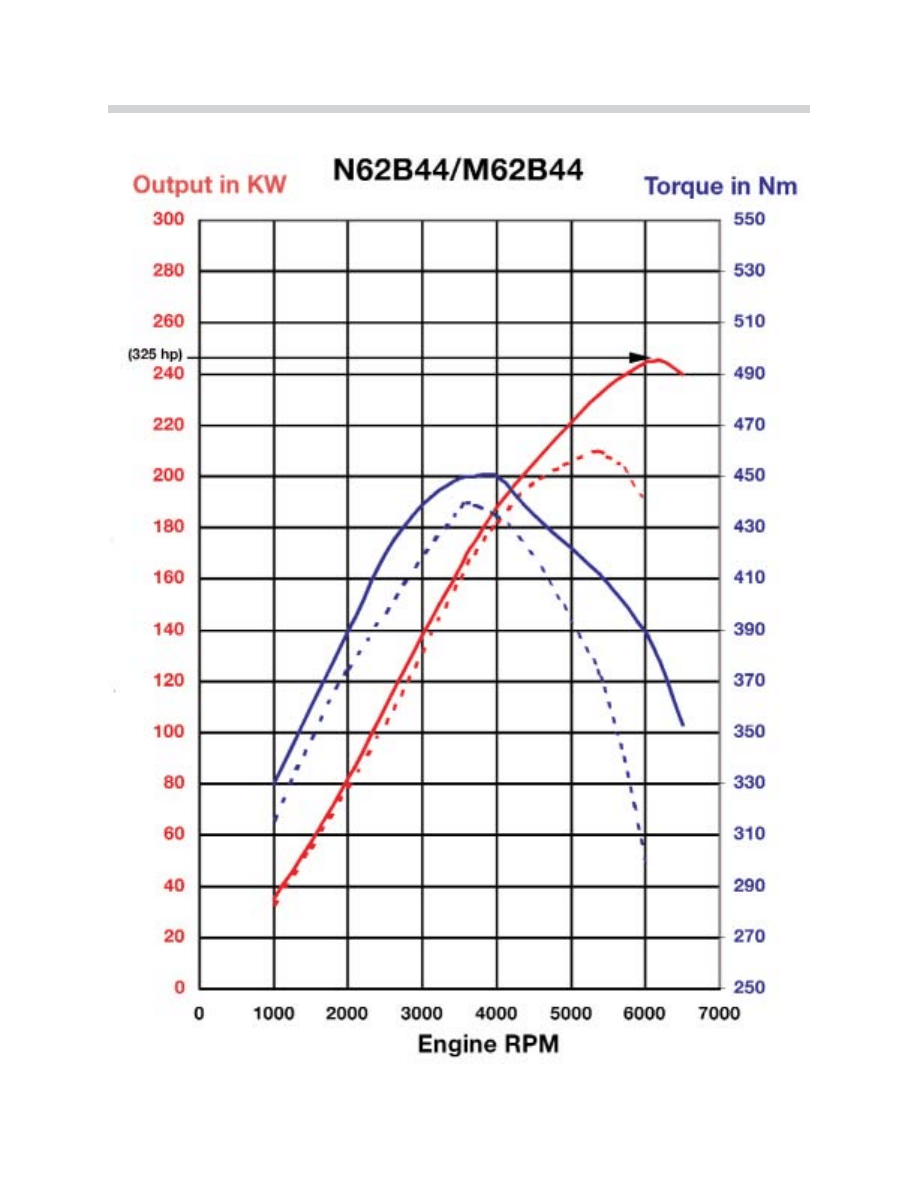
Output (kW)
at speed (rpm)
325
6,100
Torque (Nm)
at Speed (RPM)
330
3,600
Cut-off speed (RPM)
6.500
Compression Ratio
10.0
Valves / Cylinders
4
Intake Valve Diameter (mm)
35
Exhaust Valve Diameter (mm)
29
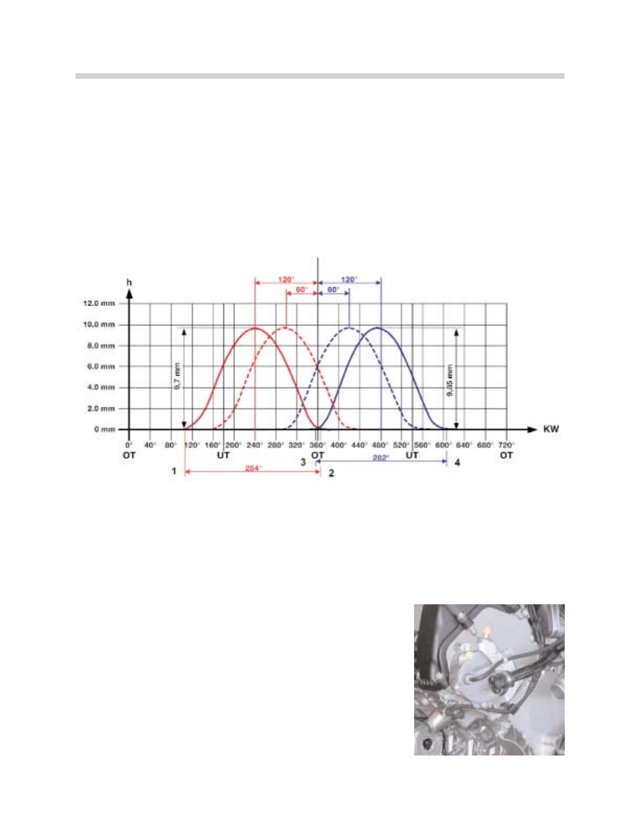
Intake Valve Lift (mm)
0.3 – 9.85
Exhaust Valve Lift (mm)
9.7
Cams Open Period (º crankshaft)
282/254
Engine Weight (kg)
213
Fuel
91 Octane
Firing Order
1-5-4-8-6-3-7-2
Knock Sensor
Yes
Variable Intake Manifold
Yes
Digital Motor Electronics
ME 9.2 with Valvetronic Control Unit
Complies with Exhaust Emission Regulations
EU-3
EU-4
LEV
Engine Length (mm)
704
Fuel Consumption Saving Compared with the M62
14%
4
N62 Engine
42-02-02
5
N62 Engine
Engine Views
1
2
3
4
5
6
7
42-02-03
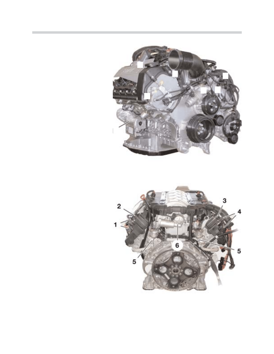
N62B44 Engine (Front View)
1. Starter Motor
2. Valvetronic Motor
3. Evaporative Emission Valve
4. VANOS Solenoid Valve
5. Thermostat Housing
6. Throttle Unit
7. Vacuum Pump
N62B44 Engine (Rear View)
1. Camshaft Position Sensor
Cylinder Bank 5-8
2. Valvetronic Eccentric Shaft
Position Sensor, Cylinder
Bank 5-8
3. Valvetronic Eccentric Shaft
Position Sensor, Cylinder
Bank 1-4
4. Camshaft Position Sensor
Cylinder Bank 1-4
5. Secondary Air Non-return Valves
6. Servomotor for Variable Intake
Manifold
42-02-04
Fresh Air System
Air Routing
The intake air passes through the air intake duct to the air cleaner, through the throttle sec-
tion into the variable intake manifold and on to the two cylinder head intake ducts.
Increases in engine output and engine torque, as well as optimization of the engine torque
curve, are largely dependent on an optimum engine volumetric efficiency over the entire
engine speed range.
Long and short intake paths contribute to good volumetric efficiency in the lower and upper
speed ranges. Long air intake paths ensure optimum volumetric efficiency in the lower to
middle speed ranges. This optimizes the torque curve and increases the torque.
In order to optimize the power increase in the upper speed range, the engine requires short
air intake paths for better cylinder filling. The air intake system has been completely rede-
velopd in order to eliminate this inconsistency in terms of air intake path length.
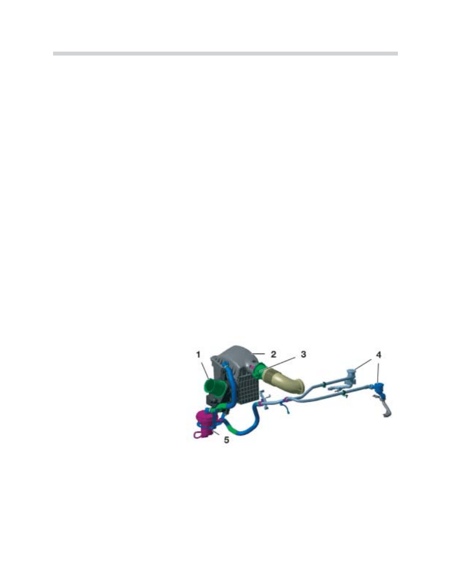
The air intake system consists of the following components:
6
N62 Engine
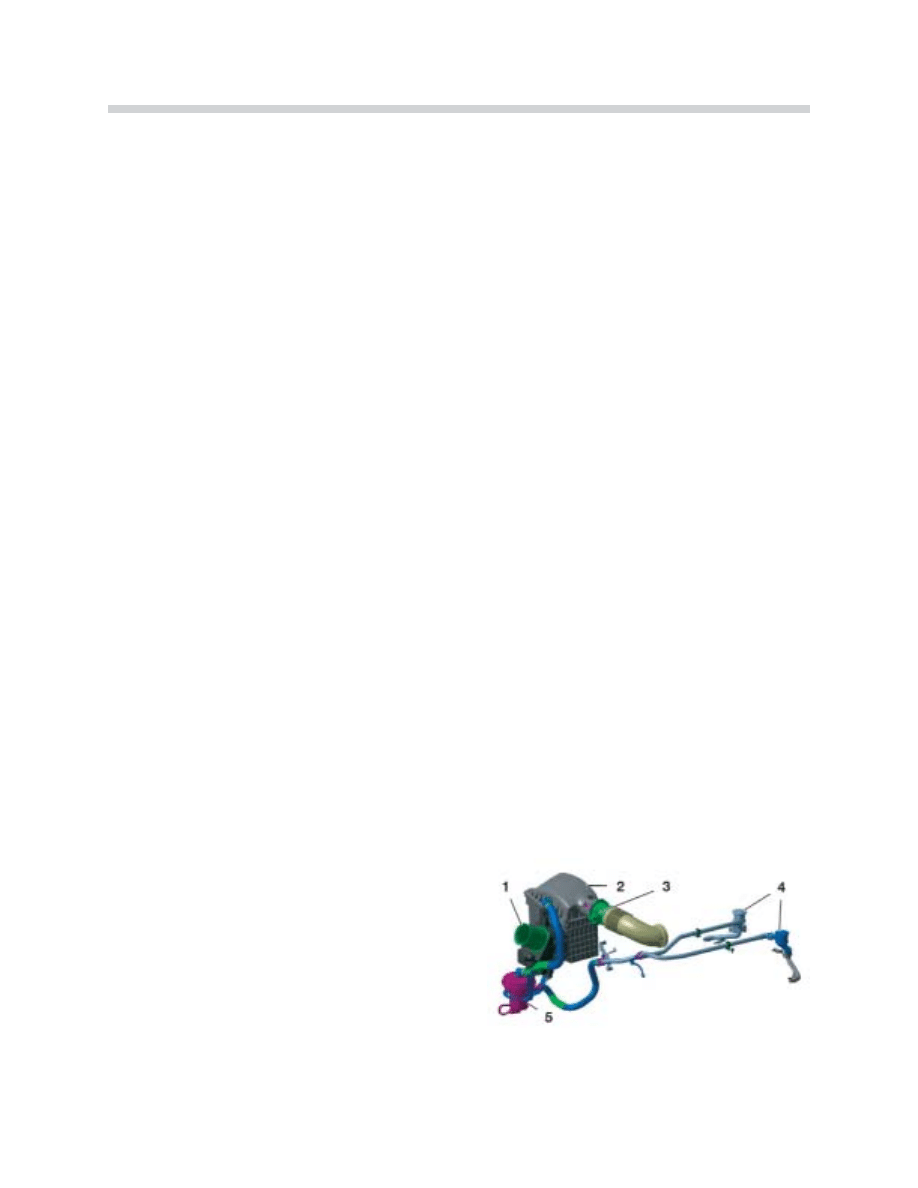
42-02-05
Air Intake System
1. Air Intake Duct
2. Air Cleaner Housing with Intake
Air Silencer
3. Intake Pipe with HFM (Hot-Film
Air-Mass Flow Sensor)
4. Secondary Air Valves
5. Secondary Air Pump
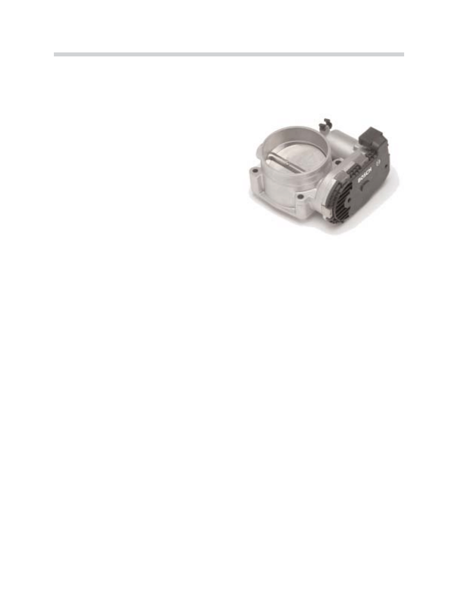
Throttle Valve
The throttle valve on the N62 is not necessary for engine load control. This is carried out
by the intake valves variable lift adjustment.
The tasks of the throttle valve are:
S
Stta
arrttiin
ng
g tth
he
e e
en
ng
giin
ne
e
Airflow is controlled by the throttle valve during the starting procedure when the air temp-
erature is between 20 ºC and 60 ºC, .
If the engine is at operating temperature, it will be switched to non-throttle mode approx-
imately 60 seconds after start up. In cold conditions however, the engine is started with
the throttle valve fully opened because this has a positive effect on the starting characteris-
tics.
E
En
ns
su
urriin
ng
g a
a c
co
on
ns
stta
an
ntt v
va
ac
cu
uu
um
m o
off 5
50
0 m
mb
ba
arr iin
n tth
he
e iin
ntta
ak
ke
e m
ma
an
niiffo
olld
d
This vacuum is needed to exhaust the blow-by gases from the crankcase and the fuel
vapors from the activated charcoal filter.
T
Th
he
e b
ba
ac
ck
ku
up
p ffu
un
nc
cttiio
on
n
If the Valvetronic system should fail, the throttle valve implements conventional load con-
trol).
7
N62 Engine
42-02-25
Throttle Valve
• Throttle Valve Housing with Throttle Valve.
• Throttle Valve Actuator
• Two Throttle Valve Potentiometers
Intake Manifold
The N62 engine is equipped with a Variable Intake Manifold making it possible to reach a
generous torque curve even at low engine speeds, without incurring losses in engine out-
put at higher speeds. It ensures that the engine exhibits optimum volumetric efficiency
through the entire range of speeds.
The new feature is the Variable Intake Manifold intake pipe length can be adjusted depend-
ing on the engine speed to provide efficient cylinder filling and scavenging. This is deter-
mined by the optimal matching of the intake pipe dimensions, the exhaust system and the
valve timing.
The intake manifold is located in the engine “V” and is mounted on the cylinder head intake
ports.
Function
In order to understand how engine speed relates to volumetric efficiency, the physical
processes within the intake pipe must be taken into consideration.
To ensure that there is good airflow to the engine cylinders, the intake pressure in front of
the intake valve should ideally be high. This means that good airflow (high gas molecule
density) in front of the intake valve is necessary.
8
N62 Engine
42-02-47
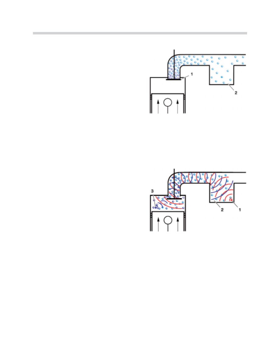
This is only possible if the intake valve is closed
and the mass inertia causes the intake air to
flow in front of the closed intake valve. The air is
compressed, the pressure and the air flow
increase.
IIn
ntta
ak
ke
e a
aiirr ffllo
ow
ws
s iin
n ffrro
on
ntt o
off tth
he
e c
cllo
os
se
ed
d iin
ntta
ak
ke
e
v
va
allv
ve
e..
1. Closed intake valve
2. Intake manifold
As soon as the intake valve is opened, the pres-
surized intake air flows into the cylinder,
expands and draws the air molecules which fol-
low into the cylinder. The suction waves form in
the intake pipe (moving at sonic speed) in the
opposite direction to the intake air.
These suction waves are reflected in the intake
manifold and create pressure waves which then
move once more at sonic speed in the direction
of the intake valve.
M
Mo
ov
ve
em
me
en
ntt o
off tth
he
e iin
ntta
ak
ke
e a
aiirr w
wiitth
h tth
he
e iin
ntta
ak
ke
e v
va
allv
ve
e
o
op
pe
en
n..
1. Pressure waves
2. Air manifold
3. Suction waves
The intake pipe is at the optimum length when the pressure waves are at the intake valve
shortly before it is closed. The increase in pressure in front of the intake valve results in
increased air flow to the cylinders once more. This process is described as recharge effect.
The opening angle of the intake valve remains unchanged as the engine speed increases.
The opening time, however, is reduced proportionately (with conventional, non-Valvetronic
engines).
Since the suction waves and pressure waves expand at sonic speed, the suction path
length must be adapted depending on the engine speed to ensure that the tip of the pres-
sure wave reaches the intake valve before it is closed.
9
N62 Engine
42-02-07
42-02-08
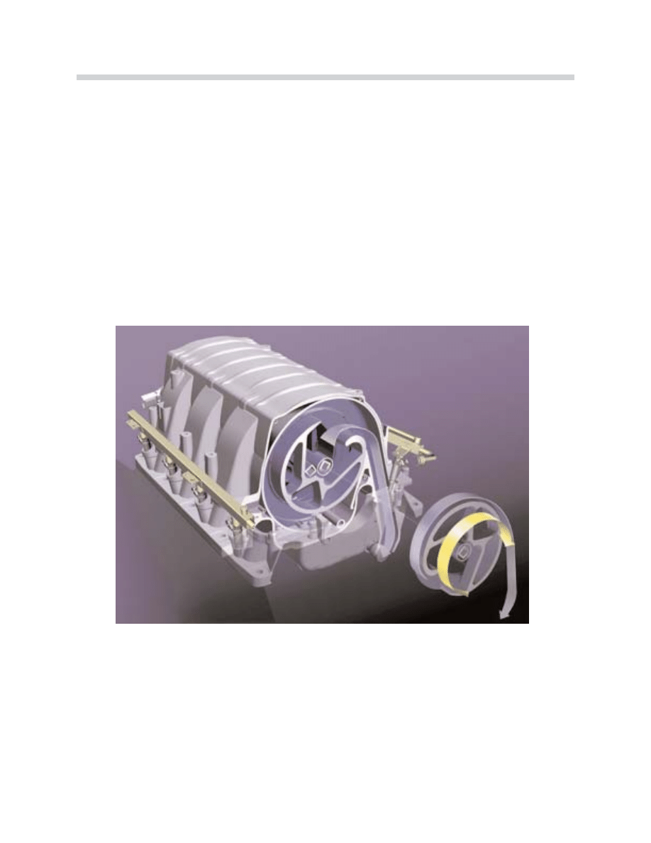
Each cylinder has its own intake pipe (1) which is connected to the manifold volume (6) via
a rotor (3). The rotors are supported by one shaft (4) per cylinder bank.
The second shaft, from which the rotor for the opposite cylinder bank is adjusted, is turned
by spur gears (5) in the opposite direction from the driven shaft.
The intake air flows via the manifold volume through the funnel (2) and on to the cylinders.
The intake path length is set as the rotor turns.
The intake path length can be adjusted according to the engine speed. Adjustment from
the long to short intake path begins at 3,500 rpm. If the engine speed increases, the intake
path length is progressively reduced, up to 6,200 rpm.
N
No
otte
es
s::
10
N62 Engine
42-02-09
The Variable Intake Manifold
1. Intake Port
2. Funnel
3. Rotor
4. Shaft
5. Spur Gears
6. Manifold Volume
The intake path length is determined by the fun-
nel position. If the engine speed is less than
3,500 rpm, the funnel is in the longer intake
path length position.
This means that the intake air must cover a
longer path to reach the cylinders.
•
• IIn
ntta
ak
ke
e m
ma
an
niiffo
olld
d s
se
ett tto
o llo
on
ng
ge
err iin
ntta
ak
ke
e p
pa
atth
h..
When an engine speed of 6,200 rpm is
reached, the rotor is adjusted to the shorter
intake path position. The intake path to the
cylinders is now short.
The funnel can be progressively adjusted to any
point between the long/short intake path posi-
tions.
•
• IIn
ntta
ak
ke
e m
ma
an
niiffo
olld
d s
se
ett tto
o s
sh
ho
orrtt iin
ntta
ak
ke
e p
pa
atth
h..
Funnel adjustment is carried out by the drive unit, which is located on the rear of the intake
manifold housing. The drive motor adjusts the drive shaft with funnels (cylinder bank 1-4).
The second shaft with funnels for cylinder bank 5-8 is synchronously adjusted by the spur
gears.
The drive motor is controlled by the ECM and
provides feedback about the funnel position via
an integral potentiometer.
11
N62 Engine
42-02-11
42-02-10
42-02-81
Crankcase Venting System
The crankcase vapors (a result of combustion blow-by gasses) are led out of the crank-
case and back into the combustion chamber via the intake manifold. The blow-by gasses
contain droplets of oil which must be separated. The oil is returned to the sump while the
blow-by gasses are led into the intake pipe for combustion.
The engine performance is affected by the introduction of crankcase vapors into the com-
bustion process, particularly in idle speed ranges. This influence is monitored by lambda
regulation.
The crankcase vapors are carried from the crankcase and into the cylinder head covers
through labyrinth separators (one per cylinder head). The oil which accumulates on the
walls of the labyrinth separators flows into the cylinder head via a siphon and from there
back to the sump.
The remaining vapors are passed to the engine for combustion via the pressure control
valve (5) in the intake manifold. One labyrinth separator with a pressure control valve is inte-
grated in each of the two cylinder head covers.
The throttle valve is controlled so that there is always a 50 mbar vacuum in the intake man-
ifold. The pressure control valve regulates the crankcase pressure to a low 0-30 mbar.
12
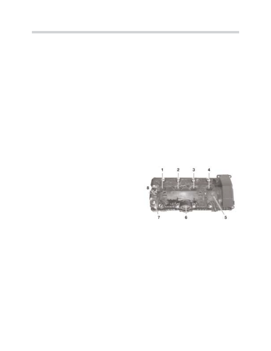
N62 Engine
43-02-12
Cylinder Head Cover
1-4. Opening for Spark Plugs
5. Pressure Control Valve
6. Opening Valvetronic Motor
7. Opening Valvetronic Sensor
Connector
8. Camshaft Sensor
Exhaust System
The exhaust system is completely redesigned for the N62B44 engine. It has been opti-
mized in terms of cylinder filling, scavenging, sound level and rapid catalytic converter light-
off.
Exhaust Manifold with Catalytic Converter
Each cylinder bank is equipped with a four into two into one exhaust manifold. The mani-
fold and the catalytic converter housing together form one component. A ceramic-bed pre-
catalytic converter and a ceramic-bed main catalytic converter are arranged one behind the
other in the catalytic converter housing.
The mounting for the broadband planar oxygen sensors (Bosch LSU) and the secondary
oxygen sensors is located in front of and behind the catalytic converter.
13
N62 Engine
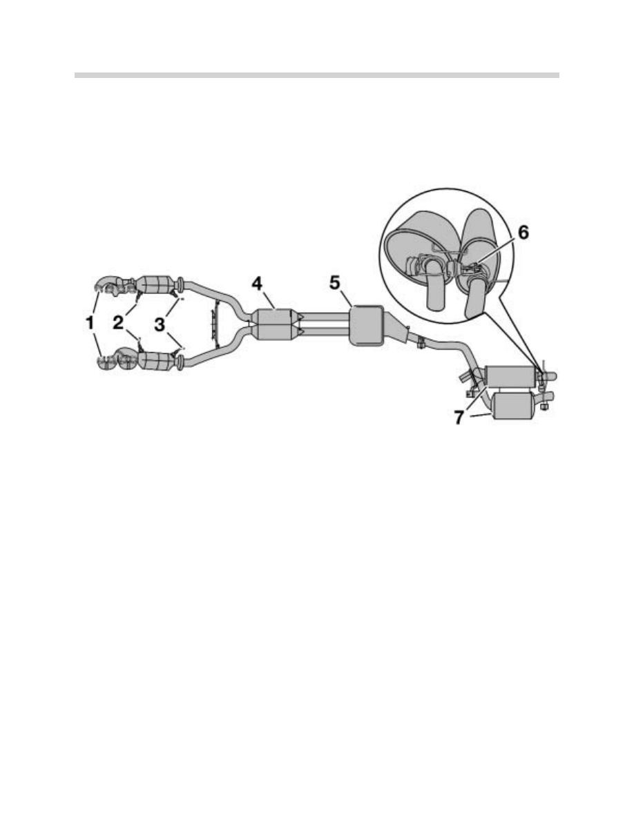
42-02-13
Exhaust System
1. Manifold with Integrated Catalytic Converter
2. Broadband Planar Oxygen Sensors
3. Secondary Oxygen Sensors
4. Exhaust Pipe with Front Silencer
5. Center Silencer
6. Exhaust Gas Flap
7. Rear Silencers
Silencers
• A 1.8 liter capacity front silencer has been fitted for each cylinder bank.
• A single 5.8 liter center silencer is fitted downstream of the two front silencers.
• The resonator type rear silencers have capacities of 12.6 and 16.6 liters.
Exhaust Gas Flap
The 12.6 liter rear silencer is fitted with an exhaust gas flap to keep noise to a minimum at
engine idle speed and low rpm. The exhaust gas flap is opened allowing additional flow
when:
• The a transmission gear is engaged a
an
nd
d
• The engine speed is above 1,500 rpm
A vacuum-controlled diaphragm (actuator mounted on the silencer) opens and closes the
exhaust gas flap. The exhaust gas flap is closed with vacuum, and is sprung open by the
actuator (when vacuum is not present). The procedure is carried out using a solenoid valve
which is electrically controlled by the ECM.
Secondary Air System
Blowing additional air (secondary air) into the cylinder head exhaust ducts during the warm-
up phase results in a thermal secondary combustion which results in a reduction of the
non-combusted hydrocarbons (HC) and carbon monoxide (CO) in the exhaust gas. The
energy generated during this process heats up the catalytic converter faster during the
warm-up phase, and increases it’s conversion rate.
14
N62 Engine
43-02-05
Secondary Air System
1. Air Intake Duct
2. Air Cleaner housing with Intake Air Silencer
3. Intake Pipe with HFM (Hot-Film Air-Mass
Sensor)
4. Non-return Valves
5. Secondary Air Pump
Secondary Air Pump (SLP)
The electrically-operated secondary air pump is mounted to the vehicle body. The pump
draws out filtered fresh air from the air cleaner housing during the warm-up phase and sup-
plies it to the two secondary air Non-return Valves.
Once the engine has been started, the secondary air pump is supplied with voltage by the
ECM via the secondary air pump relay. It remains switched on until the engine has taken in
a certain amount of air.
The O
ON
N period may be a maximum of 90 seconds and it depends on the following engine
operating conditions:
• Coolant temperature (from -10 ºC to approximately 60 ºC)
• Air temperature (NTC sensor in HFM)
• Engine speed
One non-return valve is mounted on each cylinder head (see also Engine Views).
The non-return valves are opened by the pressure generated from the secondary air pump.
The secondary air is led through a pipe to the secondary air ducts (integral in the cylinder
heads) for distribution into the exhaust ports.
The non-return valves are sprung closed when the secondary air pump is deactivated. This
prevents exhaust vapors, pressure and condensation from flowing back into the secondary
air pump.
15
N62 Engine
43-02-14
View From Rear of The Cylinder Head
1. Cylinder Head Lead
2. Non-return Valve (SLV)
3. Secondary Air Pump Connection
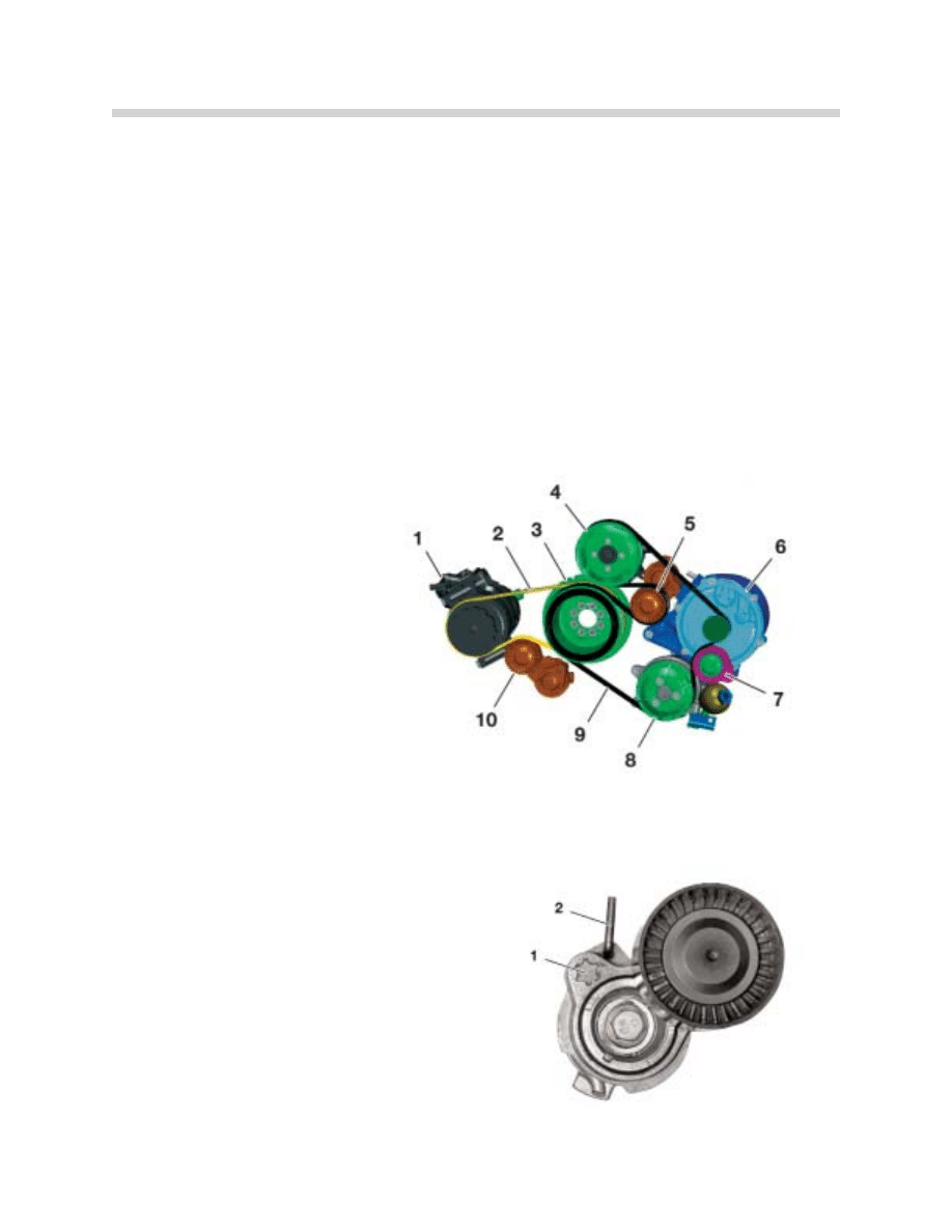
Ancillary Components and Drive Belts
Drive Belts
The belt drive has two components and is subdivided into the main and A/C drives. Both
belts are driven by the crankshaft pulley.
A 4 rib belt is used to drive the air conditioning compressor and a 6 rib belt is used for the
main drive. Each drive belt has a maintenance free tensioning unit with tensioning pulley
and torsioner.
T
To
o rre
em
mo
ov
ve
e tth
he
e d
drriiv
ve
e b
be
elltt::
The tensioning pulley is pushed back using a
Torx tool in the recess provided (1) and fixed in
this position by inserting a locking pin as shown
(2).
16
N62 Engine
42-02-15
Ancillary Components and
Drive Belts
1. Air Conditioning Compressor
2. 4 Rib A/C Drive Belt
3. Crankshaft Pulley
4. Water Pump
5. Tensioning Unit Main Drive Belt
6. Alternator
7. Deflection Pulley
8. Power Steering Pump
9. 6 Rib Drive Belt
10. Tensioner Unit A/C Drive Belt
42-02-16
Alternator
Due to the high power capacity of 180 A, the alternator is cooled by the engine's cooling
system to enhance heat dissipation. The brushless Bosch alternator is installed in an alu-
minum housing which is mounted to the engine block. The exterior alternator walls are sur-
rounded with circulated engine coolant. The function and design of the alternator is the
same as in the M62, with only minor modifications. The BSD interface (bit-serial data inter-
face) for the ECM is new.
* Further details found in the cooling circuit
section
Regulation
The alternator communicates with the Engine Control Module (ECM) via the BSD (bit-seri-
al data interface). The alternator conveys data such as model and manufacturer. This is
necessary to allow the engine management system to adapt it’s calculations and specific
control to the type of alternator fitted.
17
N62 Engine
42-02-17
Alternator
1. Watertight Housing
2. Rotor
3. Stator
4. Seal
Alternator Coolant Flow
1. Coolant Return Flow
2. Coolant Inlet Flow
42-02-18

The ECM takes on the following functions:
• Activation/deactivation of the alternator.
• Informing the alternator regulator of the nominal voltage value to be set.
• Controlling the alternator's response to load.
• Diagnosing the data line between the alternator and the ECM.
• Storing alternator fault codes.
• Activating the charge indicator lamp in the instrument cluster.
The connection with the ECM makes it possible to equalize the alternator load torque for
nearly all operating conditions. This supports the engine idling speed control and the bat-
tery load balance. In addition, the ECM receives information from the Power Module about
the battery's calculated temperature and charge status. This means that alternator output
can be adapted precisely to the temperature and load status of the battery which increas-
es the battery service life.
The charge indicator display strategy has not changed in comparison with the alternators
currently in use. Regulating the alternator output is particularly important when activating
Valvetronic operating motors.
A temperature protection function is implemented in the voltage regulator. If the alternator
overheats, the alternator voltage is reduced until an appropriate temperature has been
reached.
T
Th
he
e E
EC
CM
M c
ca
an
n rre
ec
co
og
gn
niizze
e tth
he
e ffo
ollllo
ow
wiin
ng
g ffa
au
ulltts
s::
• Mechanical faults such as blockages or belt drive failure.
• Electrical faults such as exciter diode defects or over/under voltage caused by regula-
tion defects.
• Connection defects between the ECM and the alternator.
C
Co
oiill b
brre
ea
ak
ks
s a
an
nd
d s
sh
ho
orrtt--c
ciirrc
cu
uiitts
s c
ca
an
nn
no
ott b
be
e rre
ec
co
og
gn
niizze
ed
d.. T
Th
he
e b
ba
as
siic
c a
alltte
errn
na
atto
orr ffu
un
nc
cttiio
on
n iis
s iin
n
o
op
pe
erra
attiio
on
n e
ev
ve
en
n iiff tth
he
e B
BS
SD
D iin
ntte
errffa
ac
ce
e ffa
aiills
s..
18
N62 Engine
N
No
otte
e:: The alternator regulator voltage is influenced by the ECM - BSD interface. The bat-
tery charge voltage can therefore be up to 15.5 V, depending on the battery temperature.
If a battery charge voltage of up to 15.5 V is measured, the regulator is not faulty. A high
charge voltage indicates a low battery temperature.
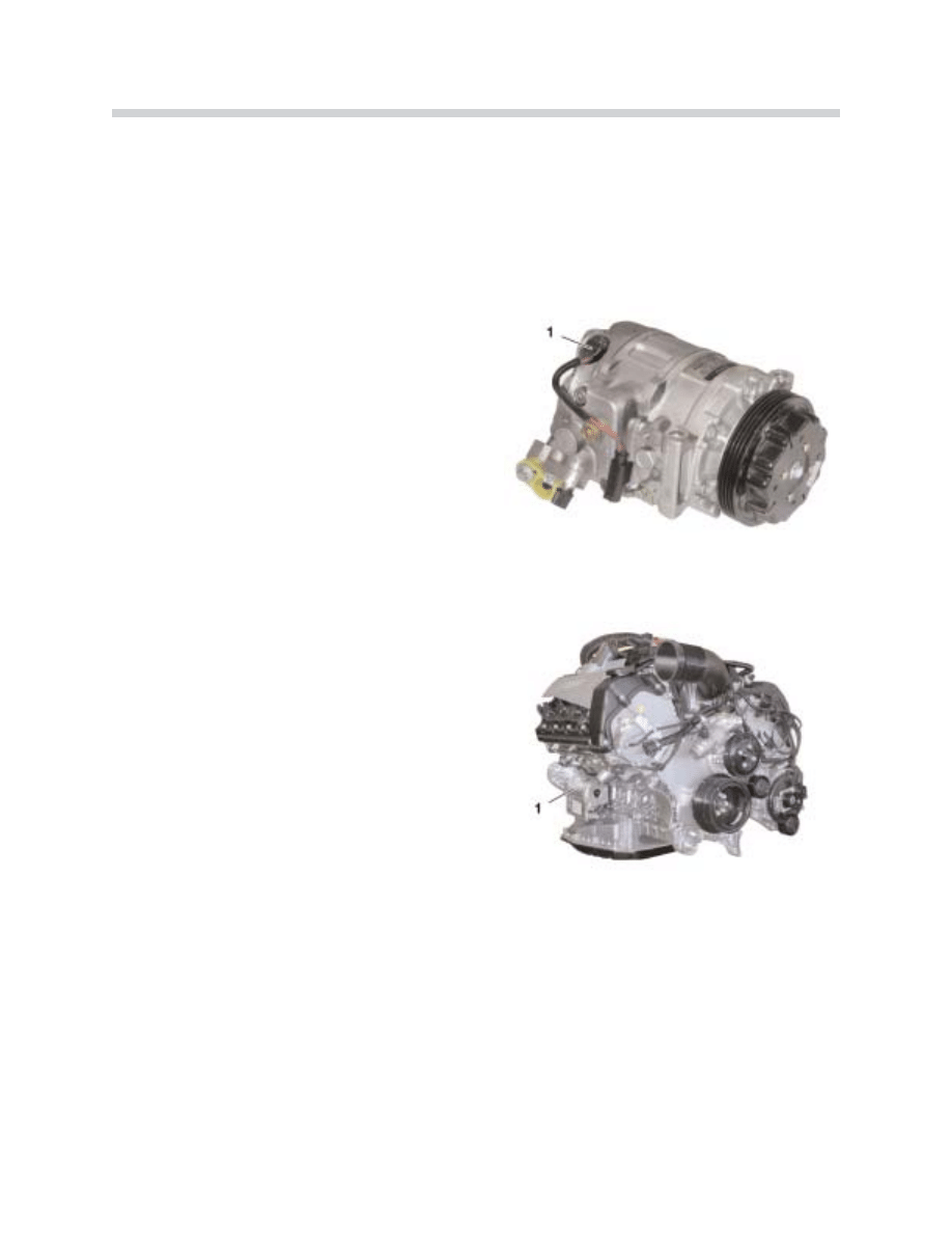
Air Conditioning Compressor
The “clutch free” A/C compressor is manufac-
tured by Denso. It functions continuously with
the engine running. The compressor is a 7-
cylinder swash plate type. The displacement
can be reduced to less than 3% when air con-
ditioning is not requested (no refrigerant is sup-
plied to the refrigerant circuit).
There is an internal compressor refrigerant cir-
cuit to maintain lubrication. The IHKA electron-
ics regulate the compressor output via an
external control valve (1).
Starter Motor
The starter motor is located on the right-hand
side of the engine below the exhaust manifold,
and is a compact planetary drive starter with a
1.8 kW output.
1. Starter motor with heat protective cover.
Power Steering Pump
The power steering pump is a tandem radial piston pump on vehicles equipped with
Dynamic Drive. A single vane pump is installed on vehicles without the Dynamic Drive.
Further information about the power steering pump can be found in the Chassis Dynamics
section.
19
N62 Engine
42-02-19
42-02-03
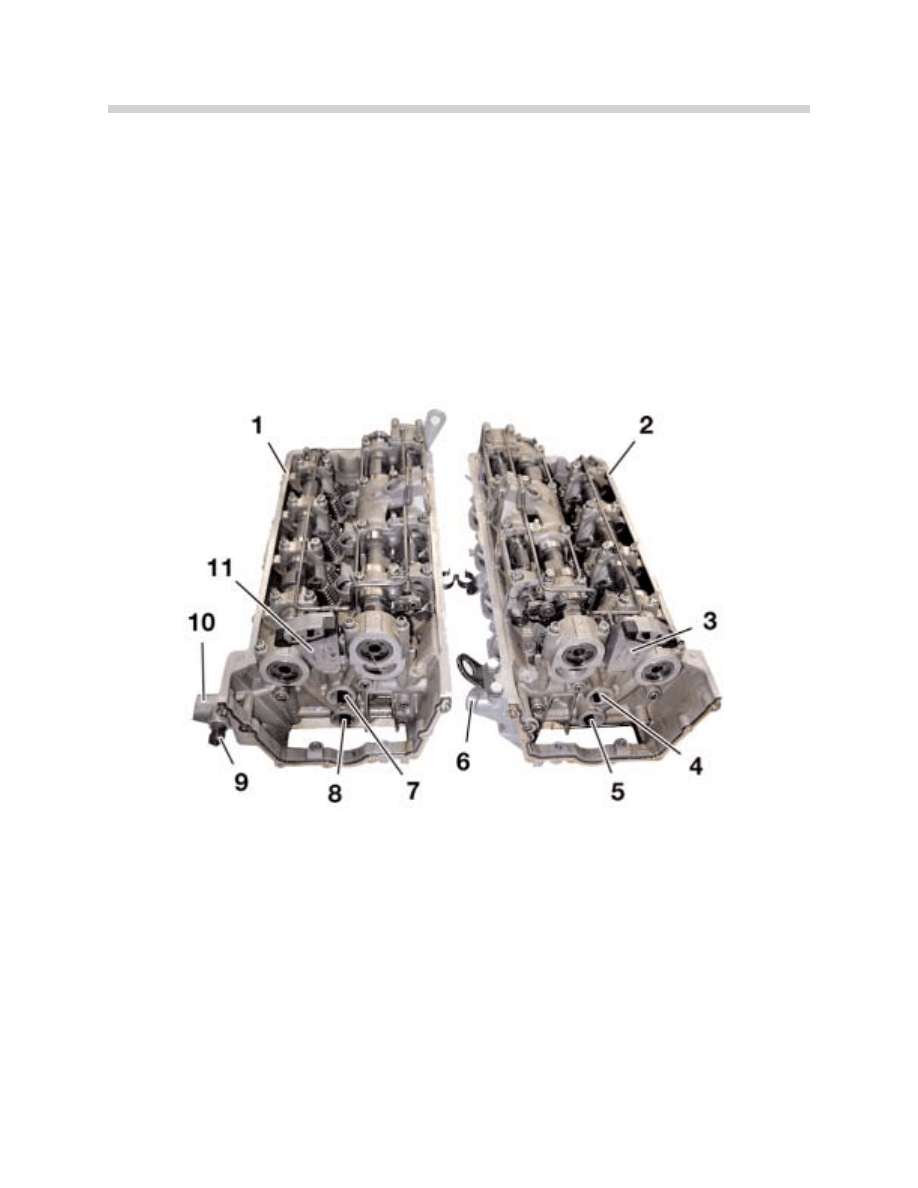
Cylinder Heads
The two N62 cylinder heads are a new development from BMW. They are fitted with the
Valvetronic system. The secondary air ducts for subsequent exhaust gas treatment are
integrated in the cylinder heads. The cylinder heads are cooled by the “cross-flow” princi-
ple.
The inlet camshaft and the Valvetronic eccentric shaft are jointly guided by a bridge sup-
port. The cylinder heads are made from aluminum and are manufactured using gravity die-
casting. The upper timing chain housing is now an integral part of the cylinder head.
20
N62 Engine
Cylinder Head
1. Cylinder Head for Cylinder Bank 1-4
7. Mounting VANOS Intake Solenoid
2. Cylinder Head for Cylinder Bank 5-8
8. Mounting VANOS Outlet Solenoid
3. Upper Timing Chain Guide with Oil Jet
9. Oil Pressure Switch
4. Mounting for VANOS Intake Solenoid
10. Chain Tensioner Mount
5. Mounting for VANOS Outlet Solenoid
11. Upper Timing Chain Guide with Oil Jet
6. Chain Tensioner Mount
43-02-20
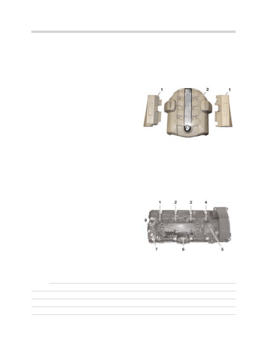
Engine Covers
Each cylinder head has a plastic cover for the ignition coil cabling and top of the cylinder
head. The covers “push fit” into rubber grommets on the cylinder head covers.
A sound absorption cover for the top of the
engine also covers the two Valvetronic motors.
This cover is fixed to the intake manifold hous-
ing using four bolts.
The cylinder head covers are made from plastic. The retaining sleeves for the ignition coils
have molded-on gaskets. The sleeves must be replaced if any hardening or damage is vis-
ible on the gaskets. The sleeves are inserted into the cylinder head through the cylinder
head cover (nos. 1through 4).
N
No
otte
es
s::
21
N62 Engine
42-02-21
Engine Covers
Cylinder Head Cover
1. Cylinder Head Top Cover
2. Sound Absorption Engine Cover
1-4. Opening for Spark Plugs
5. Pressure Control Valve
6. Opening for Valvetronic Motor
7. Opening for Valvetronic Sensor Connector
8. Camshaft Sensors (Intake and Exhaust)
43-02-12
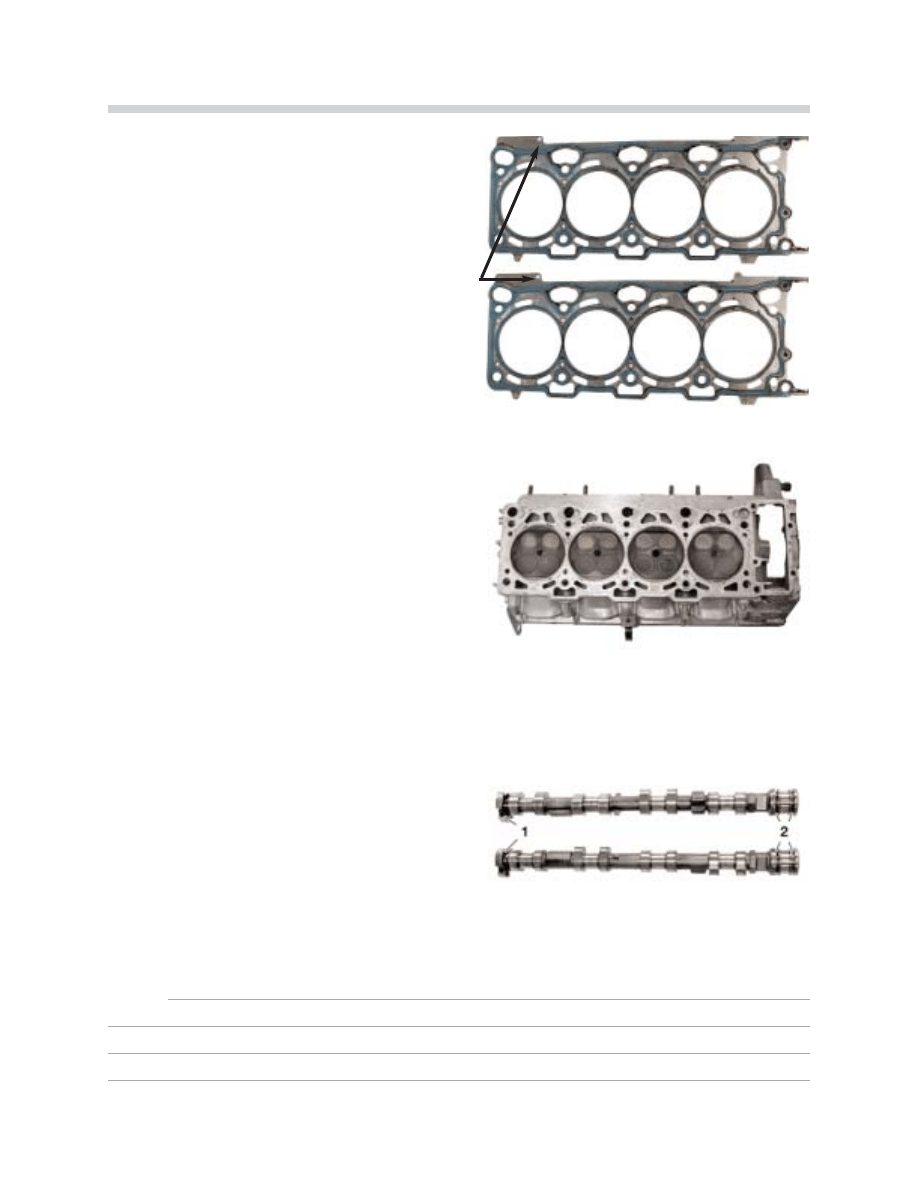
Cylinder Head Gaskets
The cylinder head gasket is a multi-layer steel
gasket with a rubber coating. This type of gas-
ket has previously been used on other engines.
The B44 head gasket has a 6 mm hole in a flap
on the outlet side of the cylinder head gasket.
The cylinder head bolts for the N62 engine are
M10x160 necked-down “stretch” bolts.
N
No
otte
e:: T
Th
he
es
se
e b
bo
olltts
s s
sh
ho
ou
ulld
d a
allw
wa
ay
ys
s b
be
e rre
ep
plla
ac
ce
ed
d
w
wh
he
en
n rre
ep
pa
aiirrs
s a
arre
e p
pe
errffo
orrm
me
ed
d..
The lower part of the timing chain housing is
bolted to the cylinder head using two M8x45
bolts.
Camshafts
The camshafts are made from chilled cast iron
and are hollowed to reduce weight. The cam-
shafts are weighted with counterbalances for
equalizing imbalances in the valve gear.
1. Camshaft sensor wheels (sintered metal)
2. Thrust bearing area with oil ducts for the
VANOS units
N
No
otte
es
s::
22
N62 Engine
42-02-23
42-02-22
42-02-24
Valvetronic
Over the entire speed and load range, the gasoline engine needs a combustible fuel-air
mixture within the ideal ratio (Lambda = 1). The mixture quantity must be altered to vary the
speed and output. This variation is effected by the throttle valve. The mixture, which falls
within the narrow range of Lambda = 1, is formed outside the combustion chamber using
the fuel injection system (external mixture formation).
The mixture control is influenced by the throttle valve and is not optimal in all the different
load ranges. This is particularly true in the idle to part-load ranges, since the throttle valve
is only opened slightly in these ranges. The consequences are less than optimal cylinder
filling, torque and increased fuel consumption.
Technical measures were previously introduced; such as the optimization of air/fuel mixing,
improved valve overlap, introduction of DISA and the steady improvement of mixture con-
trol all depend on the throttle valve. This is where the new completely unique Valvetronic
design comes in.
The Valvetronic system simultaneously varies the valve opening time and the valve opening
lift between 0.3 mm and 9.85 mm, according to engine speed and load. This means that
the air/fuel mixture volume is controlled according to engine requirements. This type of mix-
ture and volume control makes the typical throttle valve control unnecessary.
23
N62 Engine

Physical considerations:
On engines with throttle valve control, the throttle valve is slightly open in the idling and part-
load ranges. This results in the formation of up to 500 mbar vacuum in the intake manifold,
which prevents the engine from aspirating freely and in turn prevents optimum cylinder fill-
ing. The Valvetronic system with an open throttle valve largely counteracts this disadvan-
tage. The air-mass flow to the intake valves is unrestricted. The full ambient pressure is
available directly at the intake valves for cylinder filling and scavenging.
The Valvetronic system primarily controls the fill by adapting the valve opening time and the
valve lift (short opening time/small valve lift = lower fill, and vice versa). During the valve
opening phase the engine aspirates more freely via the intake valves even with small valve
lifts vs. a throttle valve which is continuously blocked.
The slower cylinder filling from the intake valves with partial lift results in more turbulence in
the combustion chamber, thus faster and better mixture control and more efficient com-
bustion. At lower engine speeds this effect is intensified by opening the intake valves later,
after top dead center (ATDC) using VANOS. This increases vacuum in the combustion
chamber which accelerates filling and turbulence when the intake valves are opened.
IIn
n s
su
um
mm
ma
arry
y,, the additional variability of the Valvetronic system results in optimization of
cylinder filling and scavenging throughout the engine's entire operating range. This has a
positive effect on output, torque and a decrease in fuel consumption and exhaust emis-
sions.
F
Fe
ea
attu
urre
es
s::
• Valve lift adjustment
• VANOS for intake and outlet
• Variable intake manifold
• Mixture control and ignition control
• Other individual engine design measures
T
Th
hiis
s rre
es
su
ulltts
s iin
n::
• Improved engine idling
• Improved engine torque
• Improved engine torque curve
• Fewer pollutant emissions
T
Th
he
es
se
e b
be
en
ne
effiitts
s rre
es
su
ulltt iin
n a
a c
clle
ea
arr iim
mp
prro
ov
ve
em
me
en
ntt iin
n p
pe
errffo
orrm
ma
an
nc
ce
e a
an
nd
d ffu
ue
ell c
co
on
ns
su
um
mp
pttiio
on
n rre
ed
du
uc
c--
ttiio
on
n ((1
14
4%
%)) ffo
orr tth
he
e d
drriiv
ve
err..
24
N62 Engine
T
Th
he
e m
ma
aiin
n b
be
en
ne
effiitts
s o
off tth
he
es
se
e ffe
ea
attu
urre
es
s a
arre
e::
• Improved cylinder filling with air/fuel mix-
ture
• Improved mixture control before the cylin-
der inlet
• Improved combustion procedure
Principle of Operation
T
Th
he
e V
Va
allv
ve
ettrro
on
niic
c s
sy
ys
stte
em
m iis
s a
a c
co
om
mb
biin
na
attiio
on
n o
off V
VA
AN
NO
OS
S a
an
nd
d v
va
allv
ve
e lliifftt a
ad
djju
us
sttm
me
en
ntt.. This combi-
nation of abilities allows the ECM to control when the intake valves are opened and closed,
and also the opening lift. The intake air flow is set by adjusting the valve lift while the throt-
tle valve is fully opened. This improves cylinder filling still further and reduces fuel con-
sumption.
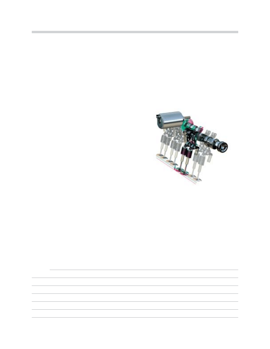
Each cylinder head in the N62 engine has a Valvetronic assembly. This Valvetronic assem-
bly consists of a bridge support with eccentric shaft, intermediate levers with retaining
springs, drag lever and the intake camshaft.
In addition, the following components belong to
the Valvetronic system:
• A Valvetronic motor for each cylinder head
• A Valvetronic control module
• A Valvetronic sensor for each cylinder head
The intake valve lift can be adjusted to anywhere between 0.3 mm and 9.85 mm.
The cylinder heads are precision manufactured together to ensure precise flow rate and
uniform distribution. The valve gear components on the intake side are precisely matched
together to the tightest limits.
The bridge support, lower eccentric shaft and inlet camshaft bearings are matched togeth-
er in the cylinder head once it is assembled. If the bridge support or the lower bearings are
damaged, the entire assembly must be replaced.
N
No
otte
es
s::
25
N62 Engines
42-02-30
Valvetronic Motors
One Valvetronic motor is located on top of each
cylinder head towards the inside of the engine
“V”. The motors are capable of traveling from
minimum to maximum lift in 300 milli-seconds.
N
No
otte
e:: The Valvetronic motor must first be removed in order to remove the cylinder head
cover. The eccentric shaft must be in the minimum lift position and the motor must be
wound out from the eccentric shaft. The worm gear could otherwise be damaged when
separating the worm shaft and the worm wheel as the eccentric shaft springs back (due to
the torque compensation spring).
IIff iitt iis
s n
no
ott p
po
os
ss
siib
blle
e tto
o rre
em
mo
ov
ve
e tth
he
e m
mo
otto
orr,, d
du
ue
e tto
o m
me
ec
ch
ha
an
niic
ca
all ffa
aiillu
urre
e o
orr s
sttiic
ck
kiin
ng
g,, tth
he
e w
wo
orrm
m
s
sh
ha
afftt c
ca
an
n b
be
e m
mo
ov
ve
ed
d u
us
siin
ng
g a
an
n A
Alllle
en
n k
ke
ey
y tto
o rre
elle
ea
as
se
e tth
he
e m
mo
otto
orr.. A
A h
ho
olle
e m
mu
us
stt b
be
e d
drriilllle
ed
d iin
n tth
he
e
rre
ea
arr p
plla
as
sttiic
c m
mo
otto
orr c
co
ov
ve
err iin
n o
orrd
de
err tto
o a
ac
cc
ce
es
ss
s tth
he
e m
mo
otto
orr s
sh
ha
afftt ((w
wo
orrm
m s
sh
ha
afftt)) u
us
siin
ng
g tth
he
e A
Alllle
en
n k
ke
ey
y..
T
Th
he
e m
mo
otto
orr c
ca
an
n tth
he
en
n n
no
o llo
on
ng
ge
err b
be
e u
us
se
ed
d..
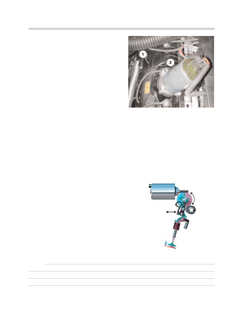
The Valvetronic motor worm gear rotates the
eccentric shaft clockwise or counterclockwise
at a very quick rate (1).
Due to the progressive “lobe” on the eccentric
shaft, this rotation positions the intermediate
lever (2) closer or further to the camshaft lobe.
N
No
otte
es
s::
26
N62 Engine
1
2
Valvetronic Motor
1. Cylinder Head Cover, Cylinder Bank 1-4
2. Valvetronic Motor for Eccentric Shaft Adjustment
42-02-29
43-22-28
27
N62 Engine
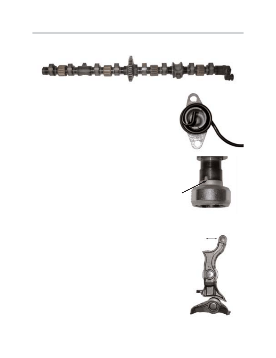
Eccentric Shafts
The eccentric shafts (one per cylinder head) are driven by the
Valvetronic motors and are supported by four caged needle
bearing assemblies for a smooth rotation.
To assist in maintaining the set positions and counter the
valve train torque, a torque compensation spring is mounted
on the end of the shaft for tension.
Magnets are fitted in the (removable) magnetic wheel at the
end of the eccentric shaft. Together with the position sensor,
the Valvetronic Control Module determines the exact shaft
position. The eccentric shaft sensor is mounted through the
cylinder head cover (one per cylinder head) at the back.
The magnetic wheel is secured to the shaft by a bolt and is
indexed by a tab (arrow) to prevent incorrect installation.
Intermediate Lever and Roller Finger
The intermediate lever is positioned further (minimum valve
opening) or closer (maximum valve opening) to the camshaft
by the the progressive “lobe” on the eccentric shaft as it is
rotated. This offers a variable ratio effect for valve actuation.
The roller finger is used to actuate the intake valve.
The intermediate levers and roller fingers are matched (by
classification) to ensure uniform valve lift.
N
No
otte
e:: W
Wh
he
en
n d
diis
sa
as
ss
se
em
mb
blliin
ng
g//a
as
ss
se
em
mb
blliin
ng
g tth
he
e v
va
allv
ve
ettrra
aiin
n,, tth
he
e
iin
ntte
errm
me
ed
diia
atte
e lle
ev
ve
errs
s a
an
nd
d rro
olllle
err ffiin
ng
ge
errs
s m
mu
us
stt b
be
e rre
ettu
urrn
ne
ed
d tto
o tth
he
e
o
orriig
giin
na
all p
po
os
siittiio
on
ns
s tto
o p
prre
ev
ve
en
ntt u
un
ne
ev
ve
en
n c
cy
ylliin
nd
de
err c
ch
ha
arrg
giin
ng
g w
wh
hiic
ch
h
c
ca
an
n rre
es
su
ulltt iin
n rro
ou
ug
gh
h iid
dlle
e a
an
nd
d e
en
ng
giin
ne
e p
pe
errffo
orrm
ma
an
nc
ce
e c
co
om
mp
plla
aiin
ntts
s..
R
Re
effe
err tto
o tth
he
e R
Re
ep
pa
aiirr IIn
ns
sttrru
uc
cttiio
on
ns
s ffo
orr tto
olle
erra
an
nc
ce
e n
nu
um
mb
be
errs
s!!
42-02-36
43-02-32
43-02-38
43-02-33

28
N62 Engine
Valve Lift
The Valvetronic motor worm gear rotates the eccen-
tric shaft clockwise or counterclockwise at a very
quick rate (1).
Due to the progressive “lobe” on the eccentric shaft,
this rotation positions the intermediate lever (2) closer
or further to the camshaft lobe.
As the camshaft is rotating (3), the cam lobe will pivot
the intermediate lever (4) and the “heel” of the inter-
mediate lever will depress the roller finger. A spring is
located on each intermediate lever to maintain con-
stant contact with the camshaft.
The roller finger is cushioned by the HVA and will open
the intake valve (5).
The Valvetronic system varies the valve opening lift
between 0.3 mm and 9.85 mm by rotating the eccen-
tric shaft during engine operation to increase or
decrease intake (flow) into the cylinder based on throt-
tle request.
* This is an assembly that affects all of the intake
valves (per cylinder head) to work in unison.
N
No
otte
es
s::
1
2
3
4
5
29
N62 Engine
Bi-VANOS (Variable Camshaft Adjustment)
The N62 features compact infinitely variable vane-type VANOS for the intake and exhaust
camshafts. The VANOS unit is easy to remove and install. The VANOS unit is designed as
an integral component of the chain drive and is secured to the respective camshaft with a
central bolt. The camshaft adjustment rate is 60º (as compared with the crankshaft).
The VANOS unit gear teeth are visibly different to match the new toothed chain. The
VANOS unit for the cylinders 1-4 exhaust shaft has mounting provisions for the vacuum
pump drive. A spring plate is fitted between the VANOS unit and the vacuum pump drive
to reduce wear (3). The V
VA
AN
NO
OS
S u
un
niitts
s a
arre
e lla
ab
be
elle
ed
d ““IIn
n//O
Ou
utt”” for intake and exhaust installa-
tion positions.
The VANOS units are supplied with oil via ports in the camshafts. The oil ports are located
on the left and right of the thrust bearing. Depending on the individual VANOS adjustment
direction, the VANOS is supplied with oil via either the rear oil ports (1 & 2) or the front oil
ports (3 & 4). The oil moves through the camshaft to the VANOS units.
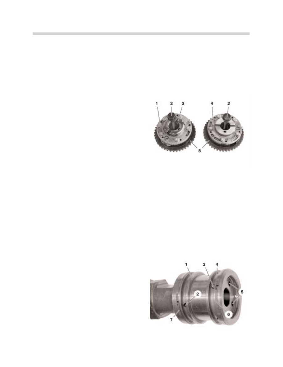
VANOS Units
1. VANOS Unit Exhaust Side
2. VANOS Central Bolt
3. Spring Plate
4. VANOS Unit Intake Side
5. Toothed Chain Gear Teeth
VANOS Oil Ports
1&2. Rear Oil Duct with Four Holes
3&4. Front Oil Duct with Four Holes
5. Front Oil Duct Outlets
6&7. Hook Sealing Washer.
43-02-39
30
N62 Engine
Camshaft Sensors
The cam shaft sensors (Hall effect) are mounted through the cylinder head cover. There are
two sensors per cylinder head to monitor the intake and exhaust camshaft positions.
The sensors monitor the impulse wheels
attached to the ends of the camshafts.
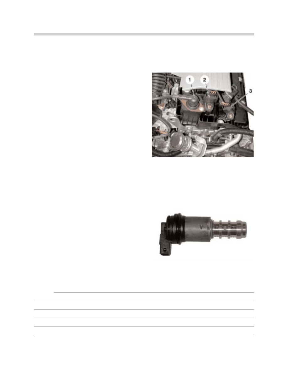
Solenoid Valves
The VANOS solenoid valves are mounted through the upper timing case front cover. There
are two solenoids per cylinder head to control the oil flow to the camshaft ports for the
intake and exhaust VANOS units.
The 4/3 way proportional solenoid valve is acti-
vated by the ECM to direct oil flow. The sole-
noid valve is sealed to the front cover by a radi-
al seal and secured by a retaining plate.
N
No
otte
es
s::
42-02-48
Camshaft Sensors
1. Valvetronic Position Sensor
2. Intake Camshaft Position Sensor
3. Exhaust Camshaft Position Sensor
42-02-42
31
N62 Engine
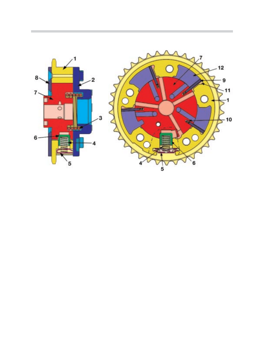
VANOS Sectional Views
M
Me
ec
ch
ha
an
niic
ca
all L
La
ay
yo
ou
utt::
The figures above show a sectional view of one VANOS unit. The VANOS unit is secured
by a central bolt through the hub (7) to the camshaft. The timing chain connects the crank-
shaft with the housing of the unit.
There is a recess in the hub in which the locking pin (6) engages without oil pressure
(sprung). When the solenoid valve is activated to supply oil pressure to the VANOS unit,
the locking pin is compressed and releases the VANOS for adjustment.
The internal blades (9) are spring loaded (10) to provide a seal between the oil pressure
chambers (11 and 12). The torsion spring (3) acts against the camshaft torque.
42-02-49
42-02-45
VANO’S Components
1. Housing with Sprocket
7. Hub
2. Front Plate
8. Black Plate
3. Torsion Plate
9. Blade
4. Lock Spring
10. Spring
5. Retaining Plate for Lock Spring
11. Pressure Chamber A
6. Spring Loaded Locking Pin
12. Pressure Chamber B
32
N62 Engine
H
Hy
yd
drra
au
ulliic
c A
Ac
cttu
ua
attiio
on
n::
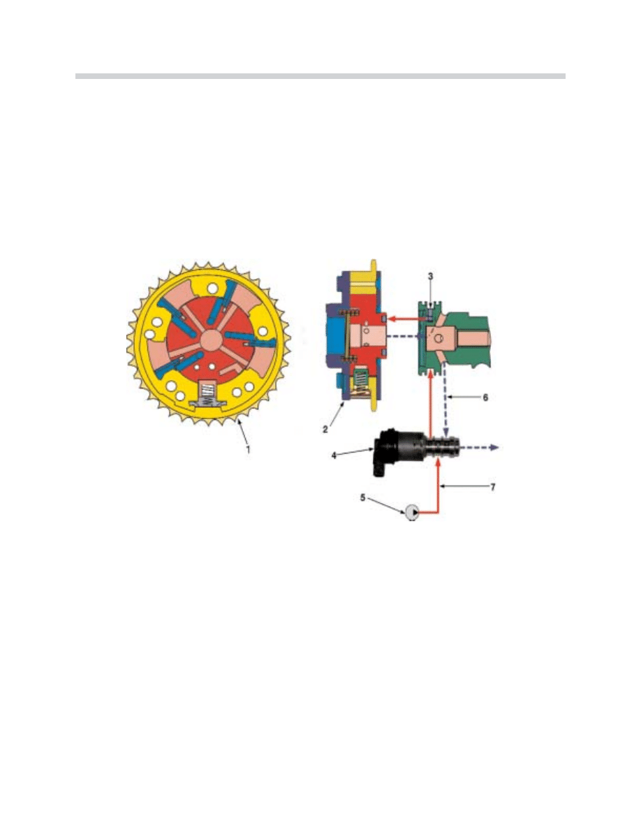
When oil pressure is applied to chamber A, the blades are forced away from the VANOS
housing (counterclockwise). The blades are keyed into the hub which results in the hub
position being rotated in relation to the housing (with sprocket). The hub is secured to the
camshaft which changes the camshaft to sprocket relationship (timing).
The example below shows the a
ad
djju
us
sttm
me
en
ntt procedure together with the pressure progres-
sion based on the VANOS unit for the exhaust camshafts.
During this adjustment chamber B is open (through the solenoid) to allow the oil to drain
back through the cylinder head (internal reservoir).
Hydraulic Actuation - Chamber A
1. Front View of Vanos Unit
5. Engine Oil Pump
2. Side View of Vanos Unit
6. Supplied Oil from Pump (Switched Through Solenoid)
3. Camshaft Oil Port (Chamber B)
7. Supplied Oil Pressure (From Engine Oil Pump)
4. Solenoid Valve
43-02-45
33
N62 Engine
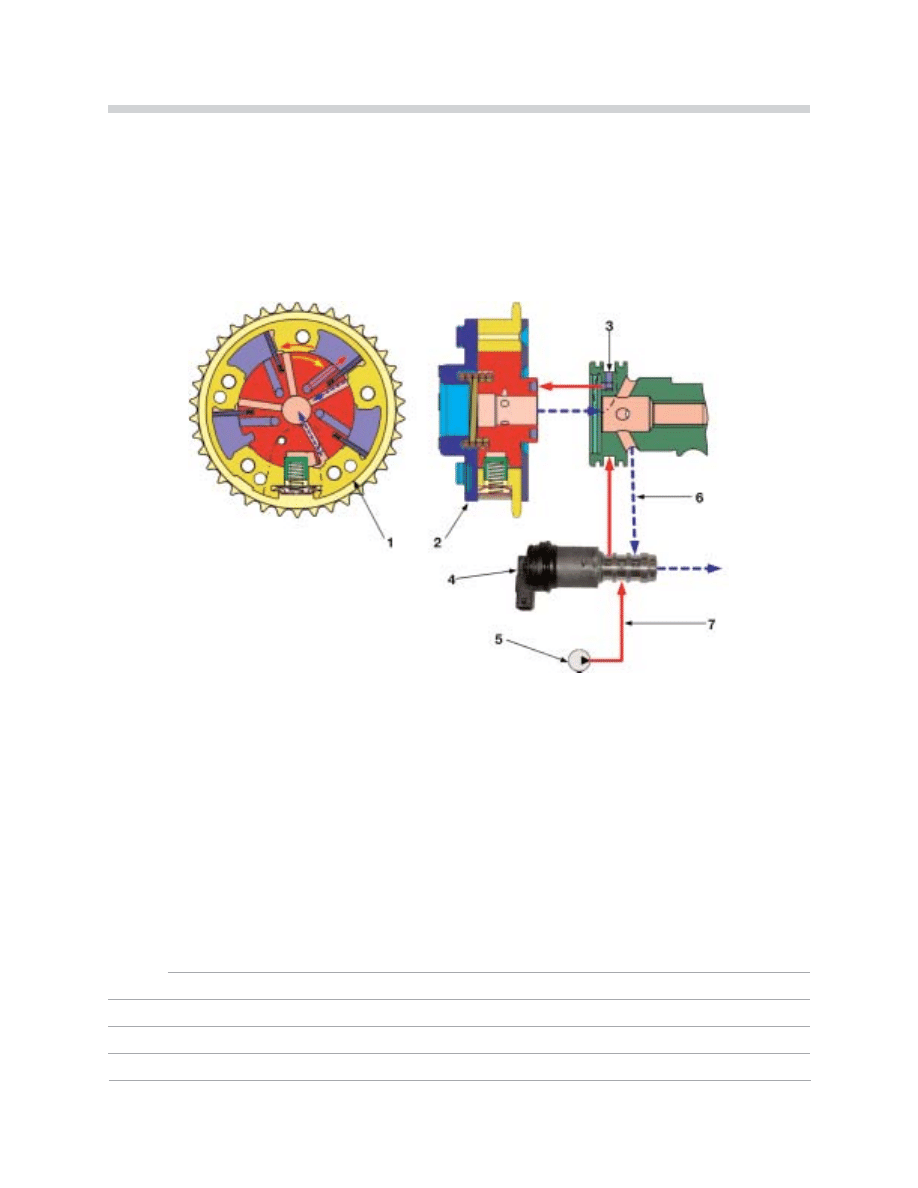
When the solenoid valve switches over, oil pressure is applied to chamber B. This forces
the blades (and hub) in a clockwise direction back to the initial position, again changing the
camshaft timing.
The example below shows the rre
es
se
ett procedure together with the pressure progression
based on the VANOS unit for the exhaust camshafts.
During this adjustment chamber A is open (through the solenoid) to allow the oil to drain
back through the cylinder head (internal reservoir).
N
No
otte
es
s::
42-02-44
Hydraulic Actuation - Chamber B
1. Front View of VANOS Unit
5. Engine Oil Pump
2. Side View of VANOS Unit
6. Oil Return (Switched through Solenoid)
3. Camshaft Oil Port (Chamber B)
7. Supplied Oil Pressure (From Engine Oil Pump)
4. Solenoid Valve
34
N62 Engine
The chart below shows the VANOS unit camshaft adjustment possibilities. The valve lift
adjustment has also been incorporated.
The special feature of Valvetronic is that the air mass drawn in the cylinders can be easily
determined by the valve lift and closing time. The air mass can then be limited, thus the
term “load control”.
With the help of VANOS, the valve closing point can be easily selected within a defined
range. With valve lift control, the opening duration and cross section of the valve opening
can also be easily selected within a defined range.
Vacuum pump
The N62 engine requires a vacuum pump for the vacuum
assisted brake booster. With the throttle valve open while the
car is being driven, additional vacuum is needed.
The N62 vacuum pump has a second vacuum connection
(small hose) for the exhaust flap adjustment. The vacuum
pump is driven by cylinders 1-4 exhaust camshaft via the
VANOS unit. The pump is lubricated through an oil gallery
from the cylinder head.
42-02-03
Chart Exhaust & Intake Valve
1. Exhaust Valve Open
2. Exhaust Valve Closed
3. Intake Valve Open
4. Intake Valve Closed

35
N62 Engine
Chain Drive
The camshafts are driven by a toothed chain, one for each cylinder bank. The oil pump is
driven by a separate roller chain.
1. Sensor wheels for the camshaft position sensor, cylinder bank 1-4
2. Tensioner Rail, Cylinder 5-8
3. Chain Tensioner, Cylinder Bank 5-8
4. Sensor Wheel for the camshaft position sensor, cylinder bank 5-8
5. Upper timing chain guide with integrated oil jet
6. Guide rail
7. Sprocket for Oil Pump Drive
8. Timing case lower section
9. Tensioning rail, cylinder bank 1-4
10. Solenoid Valve, VANOS exhaust camshaft
11. Solenoid Valve, VANOS intake camshaft
12. Upper Timing Chain Cover
13. Chain Tensioner, Cylinder Bank 1-4
14. VANOS exhaust camshaft Bank 1-4
15. Upper Timing Chain guide with integrated oil jet
16. VANOS intake camshaft 1-4
Chain Drive
43-02-50
36
N62 Engine
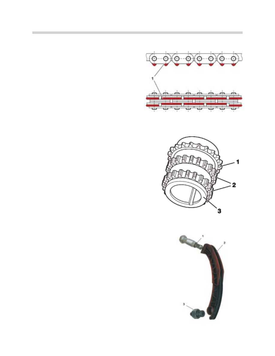
Toothed Chain
The camshafts are driven by the crankshaft
using newly developed maintenance free
toothed chains.
The toothed chain gear wheels are located on
the crankshaft and on the VANOS unit. Use of
the new toothed chains (1) optimizes the drive
chain rolling process and reduces noise.
Crankshaft Sprocket
The crankshaft sprocket (3) has three sets of gear
teeth:
1. One roller chain gear wheel for the oil pump drive.
2. Two toothed chain gear wheels for the camshaft drives.
N
No
otte
e:: The sprocket will also be fitted to a 12-cylinder
engine variant which will be available in the future.
Please observe the installation instructions and the rel-
evant labels (V8 Front/V12 Front) when installing the
sprocket.
Chain Tensioner (cylinder bank 1-4)
A chain tensioner is mounted in the side of the cylinder
head for each camshaft drive chain. There is a guide
ball in the chain tensioner tip that moves in an arched
groove in the tensioning rail.
The tensioner seal must be replaced each time the
tensioner is disassembled. The tensioners are the
same for both the left and the right cylinder heads.
42-02-51
42-02-52
Chain Tensioner
1. Chain Tensioner
2. Tensioning Rail
3. Bearing Pin
42-02-55
37
N62 Engine
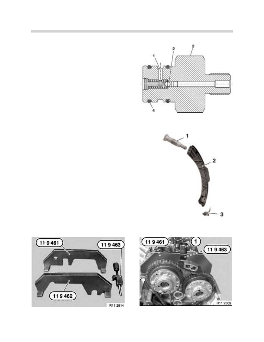
Tensioning Rail Bearing Pin
The bearing pin for the cylinder bank 1-4 drive
chain tensioning rail is hollowed. There is a ball
(check) valve in the bearing pin. The valve
opens at an oil pressure of 1 bar and allows
engine oil to flow to the tensioning rail via a port
(1).
Chain Tensioner (cylinder bank 5-8)
An oil jet has been fitted to lubricate the cylinder bank
5-8 drive chain. There is a valve in the oil jet which
opens at a pressure of 1 bar and supplies the drive
chain with engine oil.
N
No
otte
e:: Refer to the Repair Instructions when using the
Special Tools shown below to adjust the camshaft tim-
ing.
42-02-53
42-02-54
Tensioning Rail Bearing Pin
1. Engine Oil Port to Tensioning Rail
2. Ball (check) Valve
3. Bearing Pin
4. Sealing Rings for Sealing the Tensioning Rail
Chain Tensioner
1. Chain Tensioner
2. Tensioning Rail
3. Oil Jet
42-02-78
42-02-79
38
N62 Engine
Cooling System
Coolant Circuit - 14 Liter Coolant Capacity
42-02-56
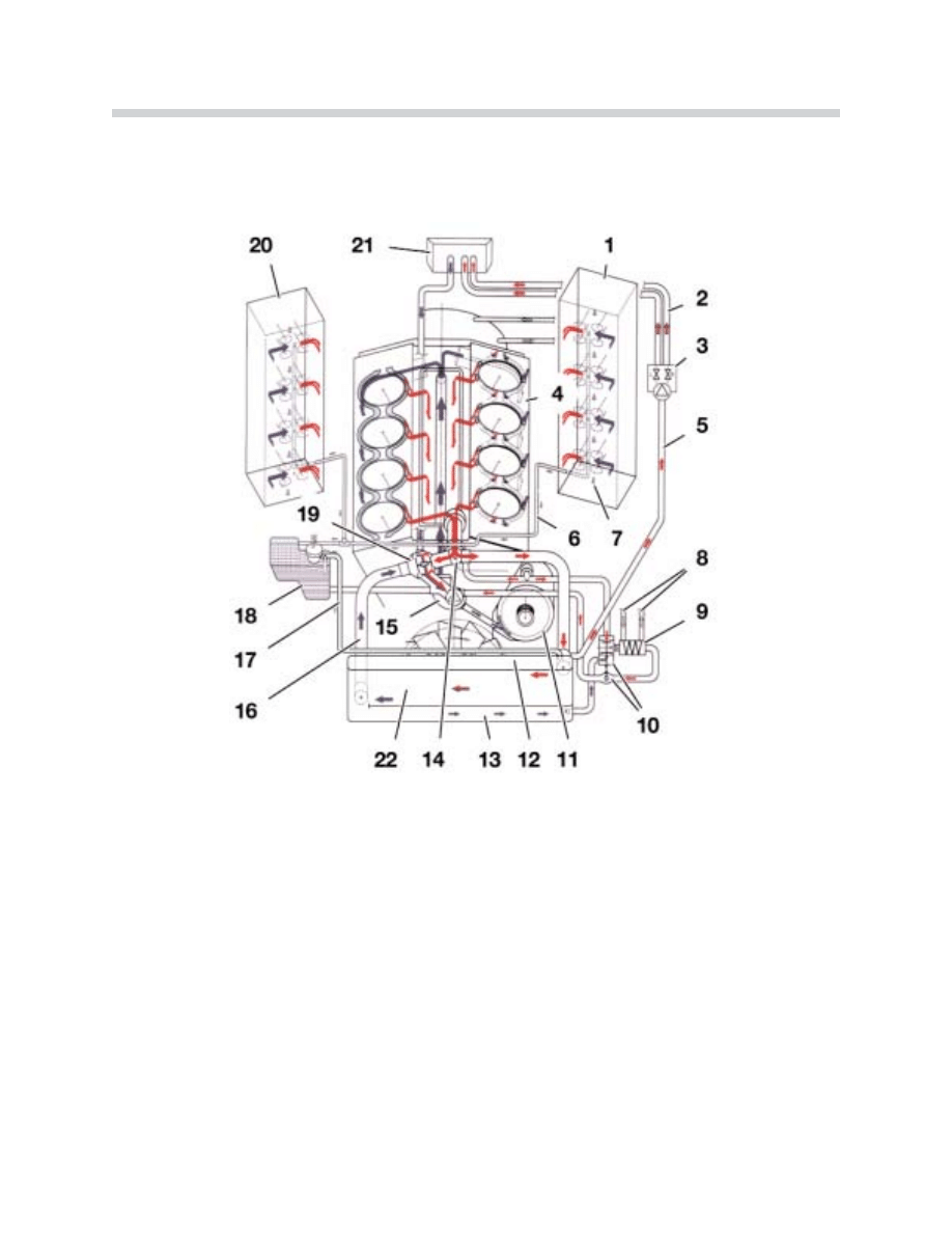
Cooling System (Circuit Flow)
1. Cylinder Head Bank 5-8
12. Radiator
2. Coolant Supply (heater core)
13. Radiator Partition (low temp section)
3. Water valve with electric water pump
14. Temperature Sensor
4. Cylinder Head Gasket
15. Water Pump
5. Coolant Supply Line
16. Radiator Return Flow
6. Cylinder Head Ventilation Lines
17. Radiator Ventilation Line
7. Hole (crankcase venting system)
18. Expansion Tank
8. Transmission oil lines
19. Thermostat
9. Oil/water heater exchanger for automatic transmission
20. Cylinder Head Bank 1-4
10. Thermostat for transmission oil heat exchanger
21. Vehicle Heater
11. Alternator Housing
22. Radiator (High Temperature Area)
39
N62 Engine
Coolant Circuit
The coolant flow has been optimized allowing the engine to warm up as quickly as possi-
ble after a cold start as well as even and sufficient engine cooling while the engine is run-
ning. The cylinder heads are supplied with coolant in a cross-flow pattern. This ensures
more even temperature distribution to all cylinders. The cooling system ventilation has been
improved and is enhanced by using ventilation ports in the cylinder heads and in the radi-
ator. The air in the cooling system accumulates in the expansion tank. When a pressure of
2 bar is reached in the expansion tank, the air is bled out by the pressure relief valve in the
reservoir cap.
N
No
otte
e:: The ventilation ports in the front of the cylinder heads provide quicker “self bleeding”
during a routine coolant exchange. The complex cooling system and the small ventilation
ports require that time should be allowed after the cooling system has been filled for the air
to escape.
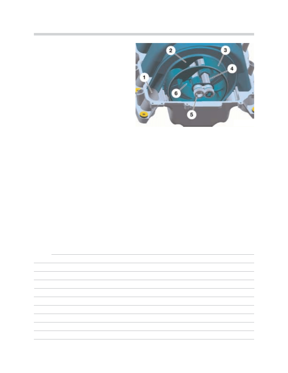
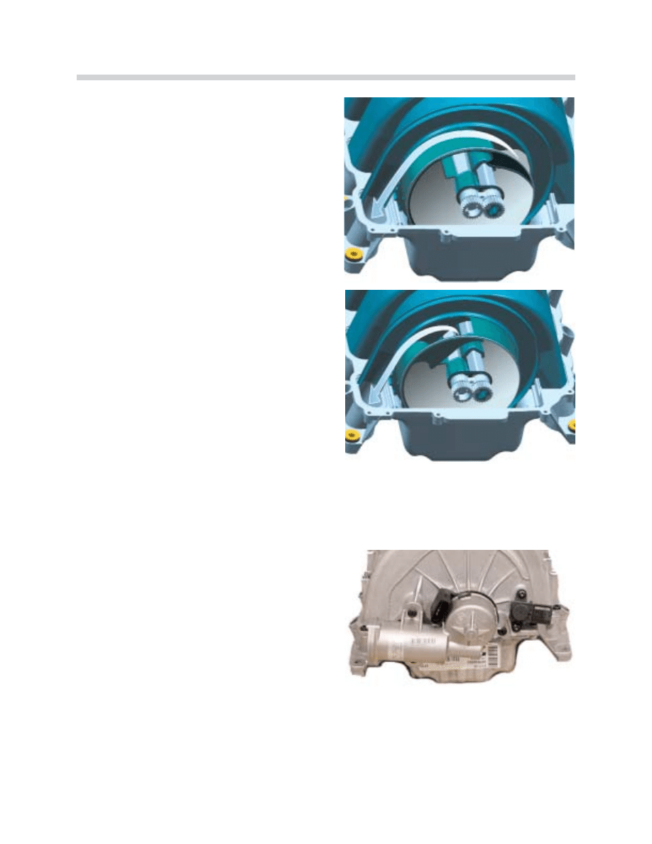
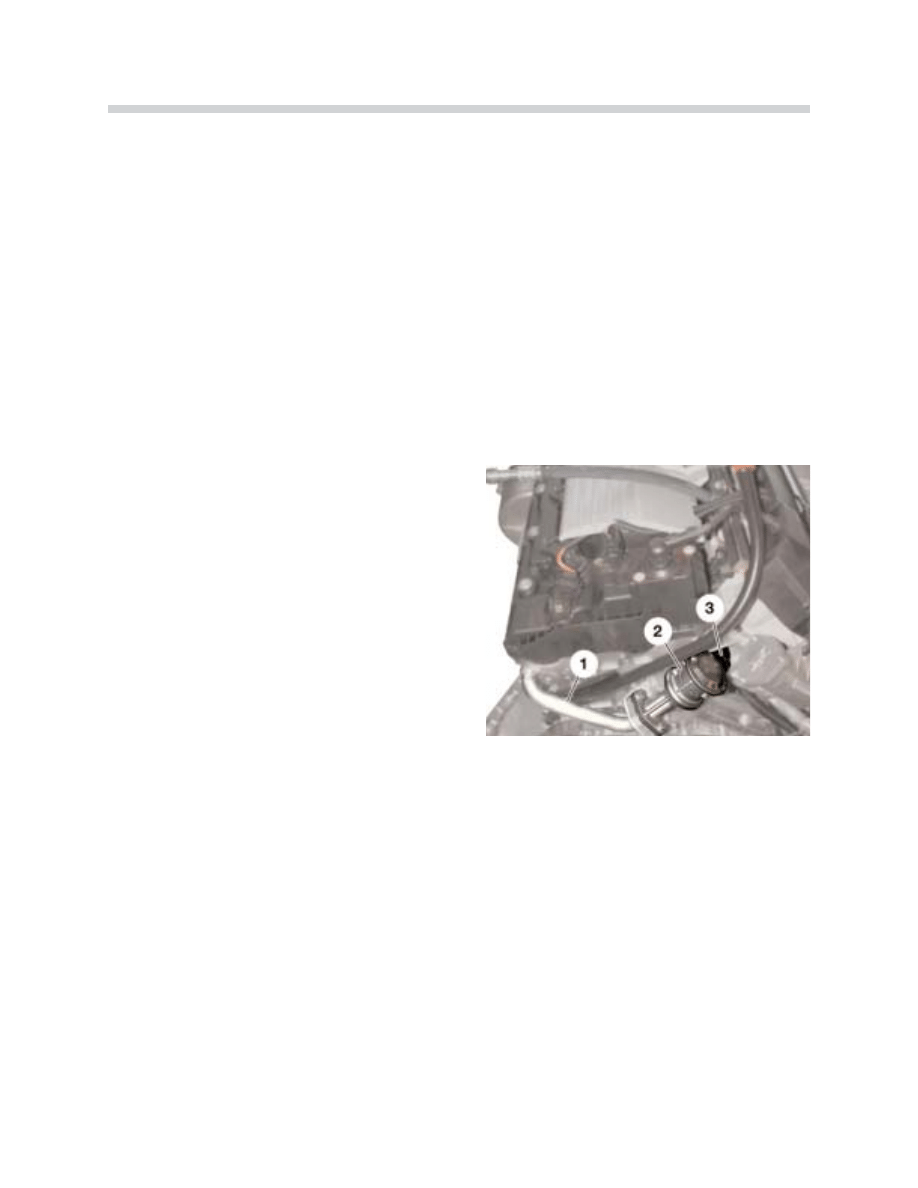
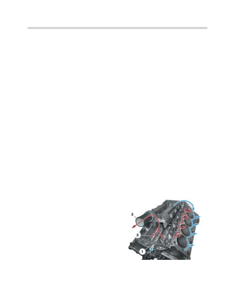
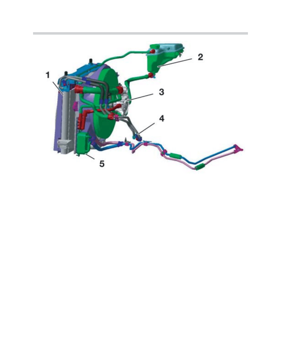
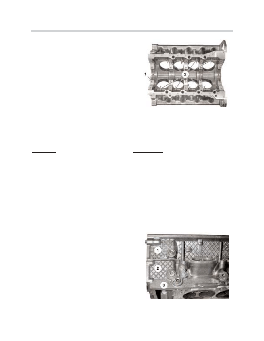
Coolant flow in the Engine Block
The coolant flows from the water pump through the feed pipe (1) in the engine's V and to
the rear of the engine block. This area has a cast aluminum cover (see following illustration).
From the rear of the engine, the coolant flows to the external cylinder walls and from there
into the cylinder heads.
The coolant then flows from the cylinder heads into the engine block V and through the
return connection (3) to the thermostat housing. When the coolant is cold it flows from the
thermostat (closed) directly into the water pump and back to the engine (recirculating for
faster warm up).
When the engine reaches operating tempera-
ture (85 ºC-110 ºC), the thermostat opens the
entire cooling circuit to include the radiator.
42-02-57
Engine Block Coolant Flow
1. Coolant from the water pump through the feed pipe
to the rear of the engine.
2. Coolant from the cylinder walls to the thermostat
housing.
3. Return connection to water pump/thermostat.
40
N62 Engine
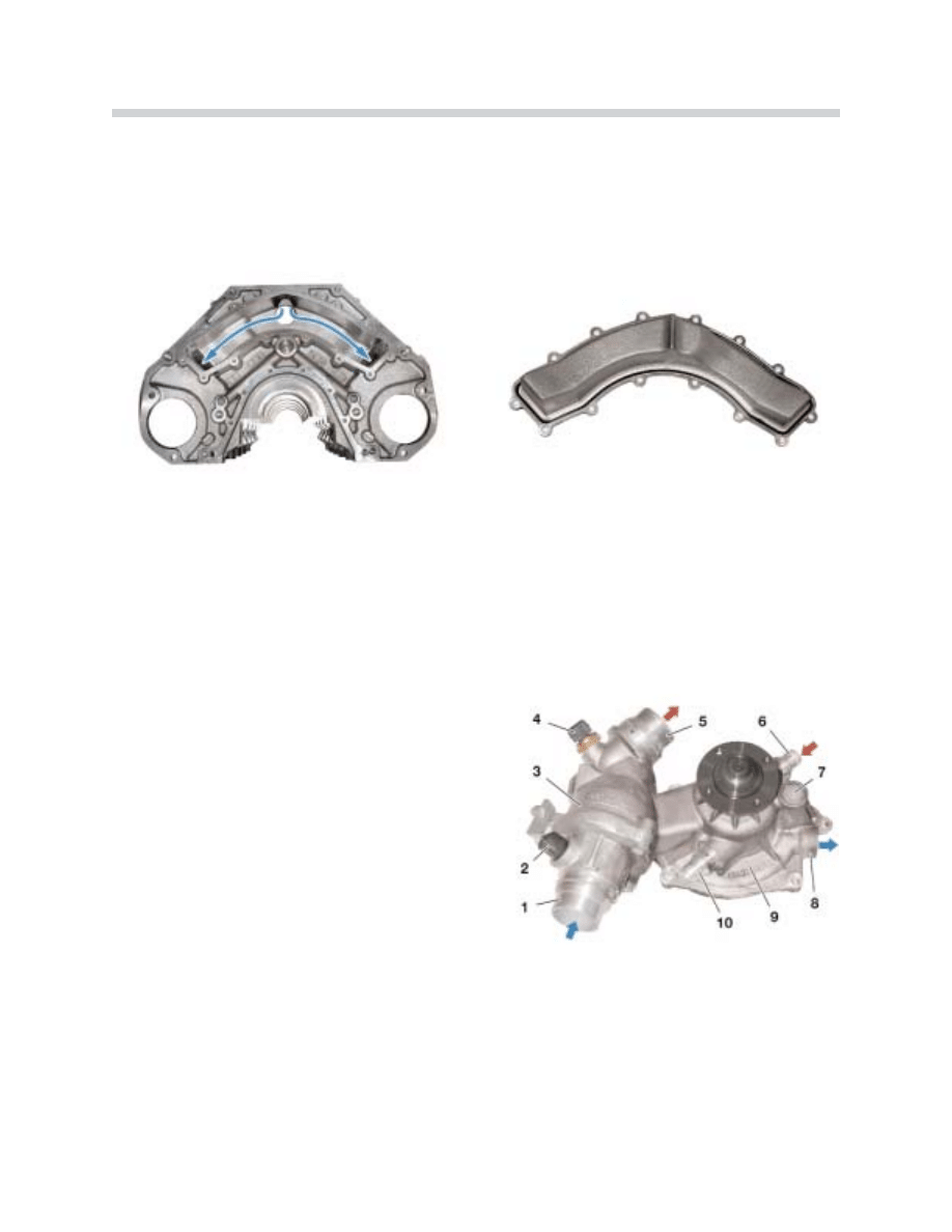
The coolant flows to the rear of the engine block, from there through the side channels to
the cylinder walls and then into the cylinder heads (lower left picture). The cast aluminum
cover at the rear of the engine block (with sealing bead) is shown on the lower right.
Water Pump/Thermostat Housing
The water pump is combined with the thermostat housing and is bolted to the timing case
lower section.
C
Ca
au
uttiio
on
n d
du
urriin
ng
g iin
ns
stta
alllla
attiio
on
n o
off tth
he
e w
wa
atte
err p
pu
um
mp
p:: The impeller is made from reinforced plastic.
42-02-59
Water Pump / Thermostat Housing
1. Map-controlled themostat (radiator cool return flow).
2. Electrical connection for Thermostat Heating element.
3. Thermostat Mixing Chamber
4. Temperature Sensor (hot coolant from engine)
5. Radiator in-flow (hot coolant from engine)
6. Heat exchanger (transmission oil return flow)
7. Leakage Chamber (evaporation space)
8. Alternator in-flow (cool supply)
9. Water Pump
10. Expansion Tank Connection
41
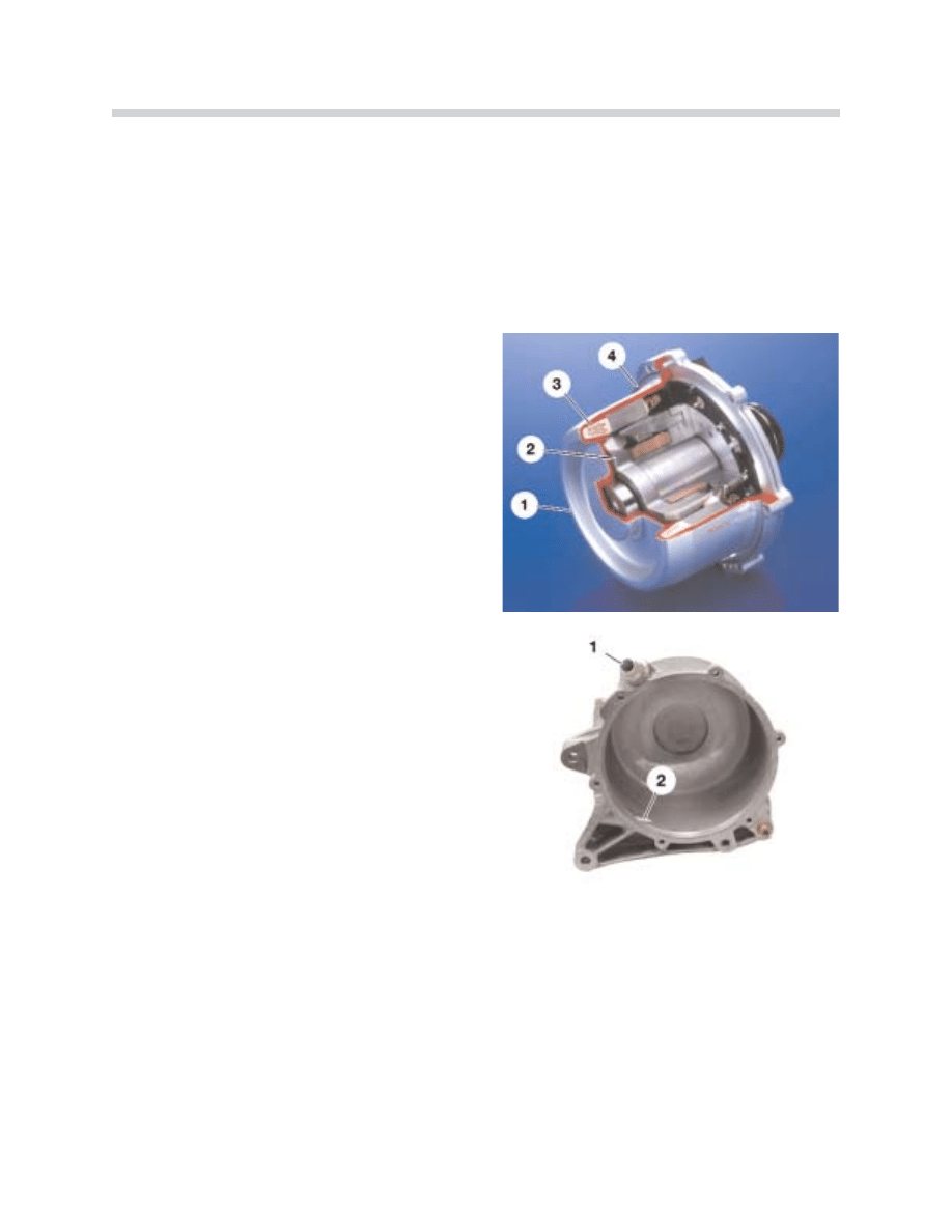
N62 Engine
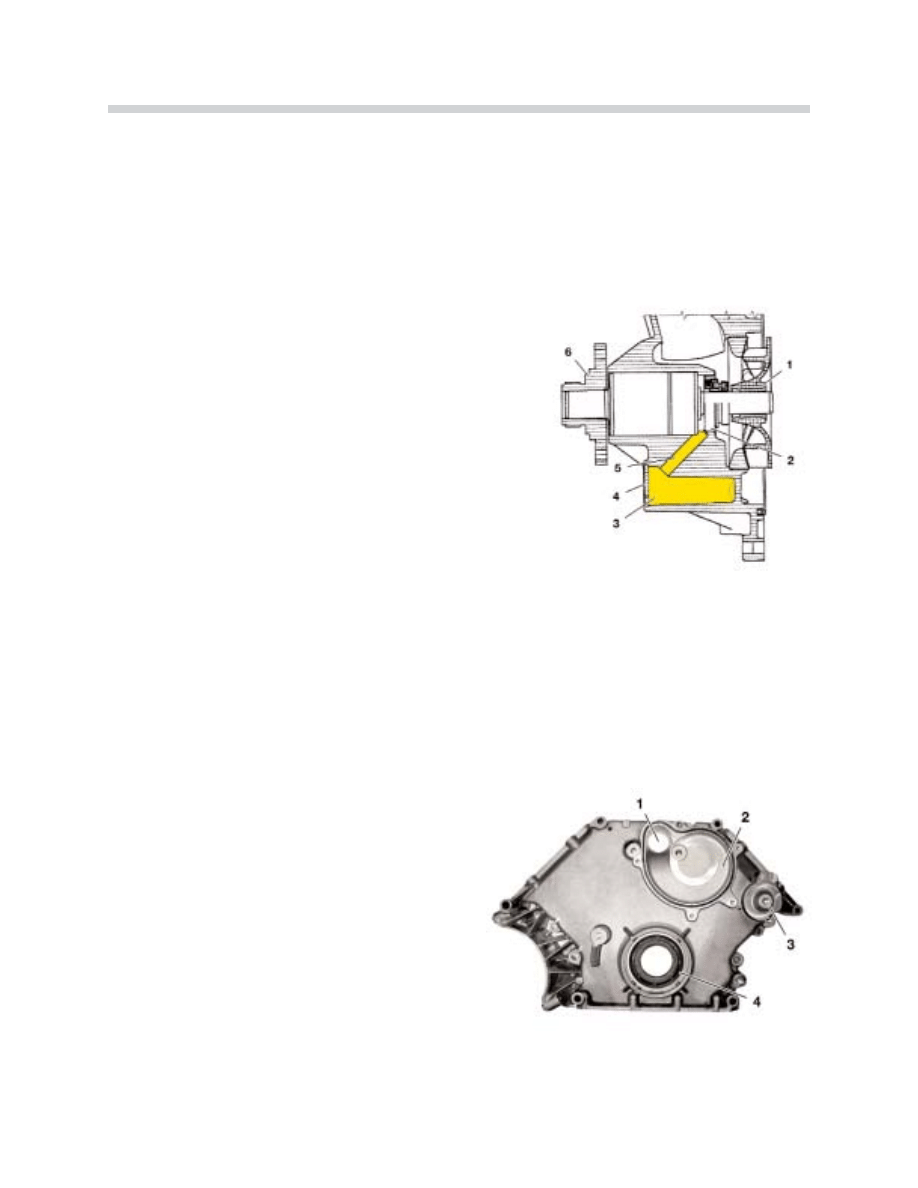
Leakage Restraint System in the Water Pump
The water pump has a leakage restraint system for the functional leakage from the pump
shaft piston ring type seal. The coolant which escapes through the pump shaft sliding ring
seal usually accumulates and evaporates through a hold in the leakage chamber (evapora-
tion area).
If the sliding ring seal is faulty, the leakage chamber fills
completely with coolant. Sliding ring seal leakages can
be detected by monitoring the fluid level in the leakage
chamber (inspection hole).
N
No
otte
e:: In the past, fully functional water pumps were often replaced because the functional
sliding ring seal leakage which is necessary for water pump operation resulted in evapora-
tion residues being left on the external walls of the water pump.
The leakage restraint system has the advantage in that the coolant escaping from the slid-
ing ring seal (normal, functional leakage) evaporates without a trace and cannot be mis-
takenly identified as a water pump defect during visual inspections.
Timing Chain Cover Lower Section
The waterpump mounts to the lower section to
channel coolant to the engine block.
42-02-61
Water Pump
1. Impeller
2. Sliding Ring Seal
3. Leakage Chamber / Evaporation Space
4. Leakage Chamber Cover
5. Delivery from the sliding ring seal to the leakage chamber
6. Hub of pulley and viscous clutch
Timing Chain Cover Lower Section
1. Coolant to Engine
2. Rear Water Pump Housing in Lower Section
3. Mount for Drive Belt Tensioner Pulley
4. Crankshaft Radial Seal
42-02-62
42
N62 Engine
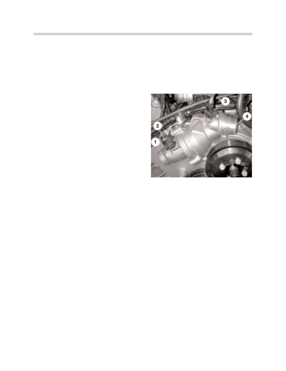
Map-controlled Thermostat
The map-controlled thermostat allows the engine to be cooled relevant to operating con-
ditions. This reduces fuel consumption by approximately 1-6%. The electrical connections,
the design and the map-controlled thermostat response have been enhanced. The map-
controlled thermostat function is the same as previous engines (M62).
Cooling Module
The cooling module contains the following main cooling system components:
• Cooling radiator
• Air conditioning condenser
• Transmission oil/water heat exchanger
• Hydraulic fluid radiator
• Engine oil radiator
• Main electric fan
• Fan shroud for viscous coupling fan
All the components (with the exception of the transmission oil radiator) can be removed for
repairs without disassembling any other coolant circuit. All connections have been fitted
with the quick-release coupling which are used in current models.
Maped-Controlled Thermostat
1. Radiator Return Flow To Thermostat
2. Connection for Thermostat Heating Element
3. Temperature Sensor
4. Radiator in-flow (hot coolant from engine)
43
N62 Engine
Cooling Radiator
The radiator is made from aluminum and is divided into a high-temperature section and a
low-temperature section by a partition wall (see coolant circuit diagram). The coolant first
flows into the high-temperature section and then back to the engine, cooled.
Some of the coolant flows through an opening in the radiator partition wall to the low-tem-
perature section where it is cooled further. The coolant then flows from the low-tempera-
ture section (when the ÖWT thermostat is open) into the oil/coolant heat exchanger.
Coolant Expansion Tank
The expansion tank is mounted on the right hand wheel housing (engine compartment).
N
No
otte
e:: The expansion tank should never be filled above the Max marking. Excess coolant is
expelled by the pressure relief valve in the cap as it heats up. Avoid overfilling the expan-
sion tank because the cooling circuit design ensures very good “self bleeding”.
Cooling Components
1. Cooling Radiator
4. Engine oil/air heat exchanger connection
2. Expansion Tank
(hot countries only)
3. Water Pump
5. Transmission oil/coolant heat exchanger

44
N62 Engine
Transmission Oil/Coolant Heat Exchanger
The transmission oil/coolant heat exchanger ensures that the transmission oil is heated up
quickly and also that it is appropriately cooled. When the engine is cold, the transmission
oil/coolant heat exchanger thermostat switches into the engine's recirculated coolant cir-
cuit. This allows the transmission oil to heat up as quickly as possible (with the engine
coolant).
When the return flow water temperature reaches 82 ºC, the thermostat switches the trans-
mission oil/coolant heat exchanger to the low-temperature coolant radiator circuit (refer to
the cooling circuit diagram) to cool the transmission oil.
Electrically Operated Fan
The electric fan is integrated in the cooling module and is mounted directly in front of the
radiator. The speed is regulated by the ECM.
Viscous Coupling Fan
The viscous coupling fan is driven by the water pump. The noise output and the perfor-
mance of the fan coupling and the fan wheel have been optimized as compared with the
E38M62. The viscous coupling fan is used as the final level of cooling and switches on at
an air temperature of 92 ºC.
N
No
otte
es
s::
45
N62 Engine
Engine Block
Oil Sump
The oil sump consists of two parts. The upper section of the oil sump is made from cast
aluminum and is sealed to the crankcase with a rubber-coated sheet steel gasket. This
section of the oil sump has a cross shaped cut out oil filter element recess. The upper sec-
tion of the oil sump is inter connected to the oil pump and is sealed with a sealing ring. The
double panel (noise insulation) lower section of the oil sump is flanged to the upper section
of the oil sump.
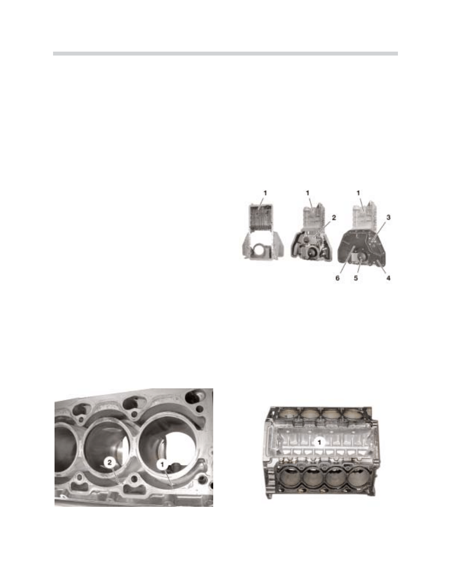
Crankcase
The crankcase has a one-piece “open deck” design and is made entirely from AluSil. The
cylinder walls are hardened using a specific procedure (exposure honing). Exposure hon-
ing involves treating the cylinders with a special “soft stripping”. This removes the aluminum
from the cylinder surface and the hard silicone particles remain.
O
Op
pe
en
n D
De
ec
ck
k =
= E
Ex
xp
po
os
se
ed
d c
cy
ylliin
nd
de
err c
co
oo
olla
an
ntt c
ch
ha
am
mb
be
err
1. Flow to engine “V” (return coolant collection area)
2. External cylinder bank wall
Oil Sump Components
1. Upper Section of The Oil Sump
2. Oil Pump
3. Oil Level / Condition Sensor
4. Lower Section of The Oil Sump
5. Oil Filter Housing
6. Oil Drain Plug
42-03-65
42-03-66
42-02-67
46
N62 Engine
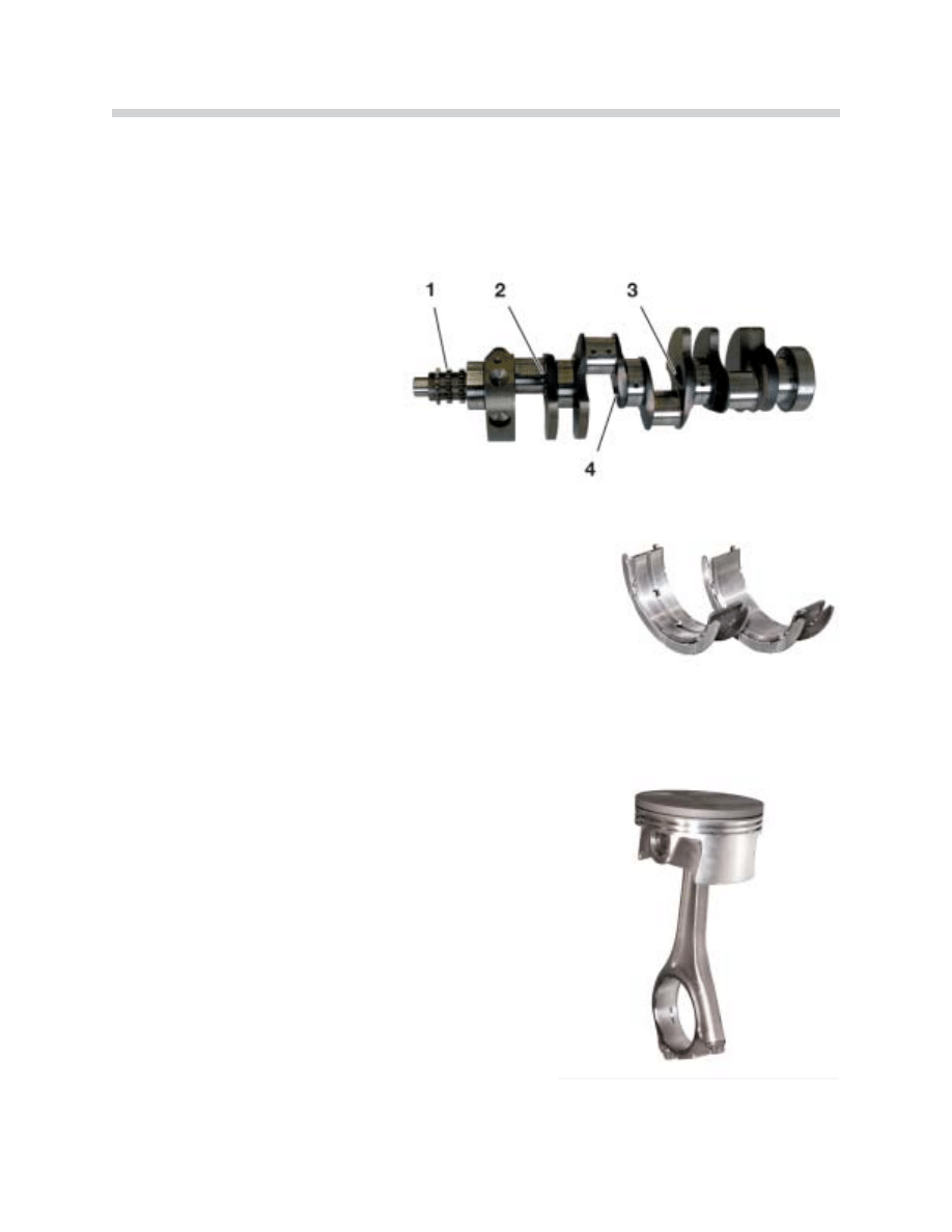
Crankshaft
The N62 uses an inductively hardened cast-iron crankshaft. The crankshaft has five main
bearings (familiar 4 bolt cast iron caps) and is hollowed around bearing journals 2, 3, and
4 for weight reduction. The fifth bearing is also the “thrust” bearing.
The crankshaft stroke for the B44
is 82.7 mm.
Crankshaft Thrust Bearing
The thrust bearing halves are multiple pieces that are assem-
bled as one part for the the number five main bearing at the
rear of the engine. The bearing thickness conforms to the
familiar triple classification system (yellow - green - white).
Piston and Connecting Rod
The reduced weight cast piston contains integrated
valve reliefs in the piston crown. The pistons are made
from high-temperature aluminum alloy equipped with
three piston rings.
• First piston ring groove = square ring
• Second piston ring groove = taperface ring
• Third piston ring groove = three-part oil control ring
The forged steel connecting rod and cap is separated
by the familiar “cracked” process. The connecting rod
(large end) is angled at 30º allowing sufficient articula-
tion in a very compact space. The pistons are cooled
by oil jets spraying under the exhaust side of the pis-
ton crown.
Crankshaft
1. Crankshaft Sprocket
2-4. Hollowed Area (Weight Reduction)
42-02-68
42-02-70
42-03-70
47
N62 Engine
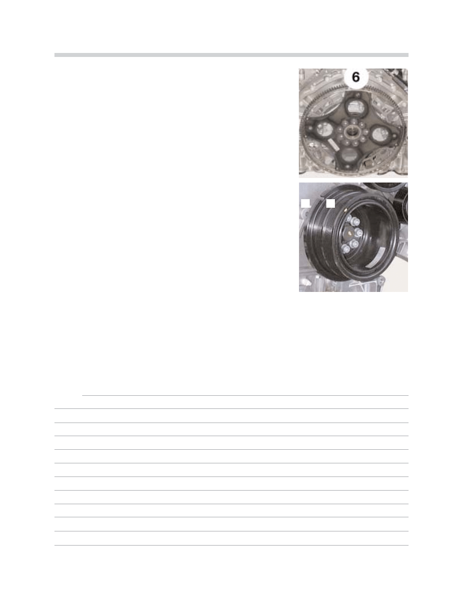
Flywheel
The lightweight flywheel is made from a laminated plate. The
starter ring gear is also the increment wheel for engine speed
and crankshaft positioning/misfire detection.
The ring gear is riveted directly to the flexplate (6). The fly-
wheel diameter is 320 mm.
Vibration Damper
The vibration damper is a torsional vibration absorber (axial
design). The outer edge of the damper has a notch (1) to
accept the locating tool when positioning the crankshaft for
initial setting.
The locating tool inserts into the raised mount in the front
cover (2). R
Re
effe
err tto
o tth
he
e R
Re
ep
pa
aiirr IIn
ns
sttrru
uc
cttiio
on
ns
s ffo
orr tth
he
e p
prro
op
pe
err
e
en
ng
giin
ne
e ttiim
miin
ng
g p
prro
oc
ce
ed
du
urre
e..
Engine Mounting
The engine is secured by two hydraulic damping mounts that are located on the front axle
carrier (structure and function are the same as the E38/M62).
N
No
otte
es
s::
1
2
48
N62 Engine
Lubrication System
Crankcase with oil jets
The engine oil is supplied by the oil pump to the lubrication points in the engine block and
is pumped into the cylinder heads. The following components in the crankcase and cylin-
der head are supplied with engine oil:
C
Crra
an
nk
kc
ca
as
se
e
• Crankshaft bearings
• Oil jets for piston cooling
• Oil jet for the drive chain (bank 5-8)
• Tensioning rail for drive chain (bank 1-4)
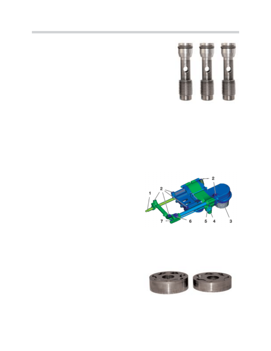
Oil Check Valves
Three oil check valves are inserted into each cylinder head from the outside. This prevents
the engine oil from draining out of the cylinder head and the VANOS units.
T
Th
he
e c
ch
he
ec
ck
k v
va
allv
ve
es
s a
arre
e a
ac
cc
ce
es
ss
siib
blle
e ffrro
om
m tth
he
e o
ou
utt--
s
siid
de
e,, tth
he
erre
effo
orre
e;; c
cy
ylliin
nd
de
err h
he
ea
ad
d rre
em
mo
ov
va
all iis
s n
no
ott
n
ne
ec
ce
es
ss
sa
arry
y w
wh
he
en
n c
ch
ha
an
ng
giin
ng
g tth
he
e c
ch
he
ec
ck
k v
va
allv
ve
es
s..
C
Cy
ylliin
nd
de
err h
he
ea
ad
d
• Chain tensioner
• Guide rail on cylinder head
• Hydraulic valve adjustment elements (HVA)
• VANOS supply
• Camshaft bearings
• Overhead oil tubes for the valve gear
42-02-71
Crankcase with Oil Jets
1. Oil Jet for Drive Chain Cylinder Bank 5-8
2. Oil Jets for Piston Cooling
42-02-72
Oil Check Valves
1. Oil Check Valve for VANOS Intake
2. Oil Check Valve for VANOS Exhaust
3. Oil Check Valve for Cylinder Head Oil Supply
49
N62 Engine
N
No
otte
e:: T
Th
he
e o
oiill c
ch
he
ec
ck
k v
va
allv
ve
es
s a
arre
e d
diiffffe
erre
en
ntt iin
n d
de
es
siig
gn
n a
an
nd
d s
sh
ho
ou
ulld
d
n
no
ott b
be
e m
miix
xe
ed
d u
up
p o
on
n iin
ns
stta
alllla
attiio
on
n..
Oil Pressure Switch
The oil pressure switch is located on the side in the bank 1-4 cylinder head.
Oil Pump
The oil pump is mounted at an angle to the crankshaft bearing cap and is driven by the
crankshaft using a roller chain. The oil pump is a two-stage gear oil pump with two paral-
lel switched gear clusters.
The two pair of gear clusters are stacked one
behind the other and work in two stages.
Stage two (both pump supply circuits) is only
active in the lower engine speed range up to
approx. 2,000 rpm to provide sufficient oil pres-
sure for the VANOS at high oil temperatures.
Stage two is deactivated hydraulically at a pres-
sure of 2 bar.
42-02-73
42-02-75
42-02-76
Oil Pump
1. Drive Shaft
2. Mounting Points
3. Oil Filter
4. Pressure Relief Valve (over 15 Bar)
5. Control Valve (Pump Stage/Pressure Control)
6. Oil supply from the oil pump to the engine
7. Oil pressure control tube from the engine to
the control valve.
50
N62 Engine
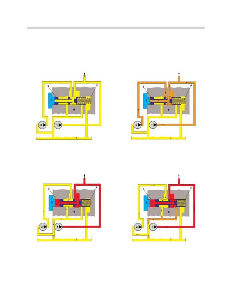
Oil Pressure Control
O
Oiill p
prre
es
ss
su
urre
e c
co
on
nttrro
oll v
va
allv
ve
e iin
n iin
niittiia
all
p
po
os
siittiio
on
n,, w
wiitth
ho
ou
utt p
prre
es
ss
su
urre
e..
S
Stta
ag
ge
e ttw
wo
o d
de
ea
ac
cttiiv
va
atte
ed
d =
= O
Oiill p
prre
es
ss
su
urre
e
a
ab
bo
ov
ve
e 2
2 b
ba
arr,, p
prre
es
ss
su
urre
e c
co
on
nttrro
oll v
va
allv
ve
e
o
op
pe
en
ns
s c
ch
ha
an
nn
ne
ell ffo
orr s
stta
ag
ge
e ttw
wo
o tto
o o
oiill
s
su
um
mp
p..
S
Stta
ag
ge
e ttw
wo
o =
= B
Bo
otth
h p
pu
um
mp
p s
su
up
pp
plly
y c
ciirrc
cu
uiitts
s
a
ac
cttiiv
va
atte
ed
d w
wiitth
h o
oiill p
prre
es
ss
su
urre
e lle
es
ss
s tth
ha
an
n 2
2 b
ba
arr..
M
Ma
aiin
n p
prre
es
ss
su
urre
e c
co
on
nttrro
oll =
= O
Oiill p
prre
es
ss
su
urre
e
a
ab
bo
ov
ve
e 6
6 b
ba
arr,, p
prre
es
ss
su
urre
e c
co
on
nttrro
oll v
va
allv
ve
e o
op
pe
en
ns
s
c
ch
ha
an
nn
ne
ell ffo
orr s
stta
ag
ge
e o
on
ne
e ((s
slliig
gh
httlly
y)) tto
o o
oiill s
su
um
mp
p
rre
elliie
ev
viin
ng
g e
ex
xc
ce
es
ss
siiv
ve
e p
prre
es
ss
su
urre
e..
Oil Pressure Control
1. Oil Pump Stage 1
5. Sealing Plug
2. Oil Pump Stage 2
6. Oil Pump Housing
3. Pressure Control Valve Piston
7. Oil Sump
4. Pressure Control Valve Spring
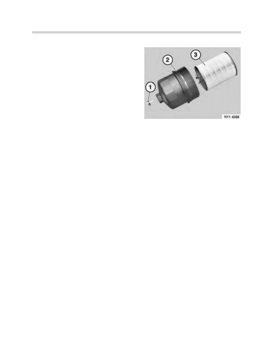
51
N62 Engine
Oil Filter
The canister type oil filter (3) is located under the
engine by the oil sump. The support for the oil
filter is integrated in the rear oil pump cover.
The oil filter housing (2 with o-ring) is threaded
into the rear of the oil pump cover through an
opening in the oil sump.
A
A d
drra
aiin
n p
pllu
ug
g iis
s iin
ntte
eg
grra
atte
ed
d iin
n tth
he
e o
oiill ffiilltte
err h
ho
ou
us
siin
ng
g
ffo
orr d
drra
aiin
niin
ng
g tth
he
e ffiilltte
err a
as
ss
se
em
mb
blly
y b
be
effo
orre
e tth
he
e h
ho
ou
us
s--
iin
ng
g iis
s rre
em
mo
ov
ve
ed
d ((1
1 w
wiitth
h o
o--rriin
ng
g))..
The filter element support dome contains an over pressure relief valve. If the filter element
is blocked, this valve bypasses unfiltered engine oil around the element to the supply lubri-
cation to the engine.
Pressure Control
The oil pressure control valve in the oil pump has two functions:
1. Deactivates stage two oil pump circuit above 2 bar. Stage two is only active in the
lower speed range. This is to ensure that there is always sufficient oil pressure for
the VANOS units even at high oil temperatures and low speeds. The oil pump power
consumption is reduced by deactivating stage two.
2. Monitoring the required oil pressure for the engine. The piston in the control valve is
moved by a spring against the engine control pressure which is returning from the
engine. This means that precise monitoring of the actual engine oil pressure is pos-
sible.
A
A s
se
ep
pa
arra
atte
e p
prre
es
ss
su
urre
e rre
elliie
eff v
va
allv
ve
e iin
n tth
he
e o
oiill p
pu
um
mp
p a
au
utto
om
ma
attiic
ca
alllly
y o
op
pe
en
ns
s a
att tth
he
e m
ma
ax
xiim
mu
um
m p
prre
es
s--
s
su
urre
e o
off a
ap
pp
prro
ox
xiim
ma
atte
elly
y 1
15
5 b
ba
arr.. T
Th
hiis
s p
prre
ev
ve
en
ntts
s d
da
am
ma
ag
ge
e iin
n tth
he
e o
oiill p
pu
um
mp
p e
es
sp
pe
ec
ciia
alllly
y a
att llo
ow
w o
oiill
tte
em
mp
pe
erra
attu
urre
es
s..
42-02-77

52
N62 Engine
Oil Cooling (if equipped)
An oil cooler is used in hot countries. The oil cooler is located in front of the radiator above
the A/C condenser. The engine oil flows from the oil pump through a channel in the
crankcase to a connection on the generator support. The generator support has an oil ther-
mostat. A wax element in the oil thermostat continuously opens the inflow to the oil cooler
when the oil temperature is between 100 ºC to 130 ºC.
Some of the engine oil always flows past the oil thermostat and through the engine with-
out being cooled, even when the oil thermostat is fully open. This ensures a minimum
amount of oil is supplied when the cooler is faulty. A modified generator support, without
connections for the oil thermostat, is fitted to vehicles which do not have an oil cooler.
Technical Data - Lubrication System
The recommended oil is BMW High Performance 5W-30 Synthetic Oil
* P/N 07 51 0 017 866
O
Oiill C
Ca
ap
pa
ac
ciittyy iin
n L
Liitte
errs
s E
Ex
xp
plla
an
na
attiio
on
n
8.0
Filling Capacity for Service with Oil Filter Change
O
Oiill P
Prre
es
ss
su
urre
e E
Ex
xp
plla
an
na
attiio
on
n
1.0
Minimum Oil Pressure at 20ºC
4.0 - 8.0 Bar Maximum Oil Pressure at 20ºC
O
Oiill D
De
elliivve
erryy C
Ca
ap
pa
ac
cii ttyy E
Ex
xp
plla
an
na
attiio
on
n
9-12 I/Min At Idle Speed (700 rpm) at 20ºC
50-55 I/Min At Maximum Engine Speed (6500 rpm) and 20ºC

53
N62 Engine
Review Questions
1. What is the function of the throttle valve?
2. What are the conditions that will result in stage two oil supply?
3. What does the term “cracked” connecting rod mean?
4. What does the low temperature area refer to in the cooling system?
5. What is the difference between the left and right drive chain tensioning assemblies?
6. How is the funnel adjustment made on the 5-8 Variable intake manifold if only one
actuating motor is used?
7. What is minimum and maximum valve lift provided by the Valvetronic system?
8. What is chamber A and chamber B used for in the Bi-VANOS system?
9. What retains the initial VANOS sprocket to hub position when oil pressure is not pre-
sent?
10. How should the drive belt be removed?
Document Outline
- Main Menu
- N62 Engine
- Part 1 ME 9.2 DME
- Part 2 ME 9.2 DME
- N73 Engine
- MED 9.2.1
- GA6HP26Z Auto Trans
- Suspension & Steering
- Brakes
- Driving Dynamics
- E65/66 Air Suspension
- Service
Wyszukiwarka
Podobne podstrony:
E65 Complete Vehicle (Part 1)
01 E83 Complete Vehicle
01 E85 Complete Vehicle
1 M3 Complete Vehicle
01 E60 M5 Complete Vehicle
M5 Complete Vehicle
01 E63 64 Complete Vehicle
(not complete) [Concord][Armor at War Mini 7515] Stryker Interim Armored Vehicle
lecture3 complexity introduction
GbpUsd analysis for July 06 Part 1
~$Production Of Speech Part 2
L 3 Complex functions and Polynomials
20 H16 POST TRANSFUSION COMPLICATIONS KD 1st part PL
Discussions A Z Intermediate handout part 1
part 20
Eurocode 3 Part 1 11 Pren 1993 1 11 (Eng)
Part 2
C102723 D W0064 CIR PART
hejka, IV rok, IV rok CM UMK, Kardiologia, giełdy, part I
więcej podobnych podstron