
Initial Print Date:09/02
Revision Date:
Subject
Page
History . . . . . . . . . . . . . . . . . . . . . . . . . . . . . . . . . . . . . . . . . . . . . . . . .4
Design . . . . . . . . . . . . . . . . . . . . . . . . . . . . . . . . . . . . . . . . . . . . . . . . .5
Hood . . . . . . . . . . . . . . . . . . . . . . . . . . . . . . . . . . . . . . . . . . . . . . . . .10
Headlights . . . . . . . . . . . . . . . . . . . . . . . . . . . . . . . . . . . . . . . . . . . . .10
Front bumper . . . . . . . . . . . . . . . . . . . . . . . . . . . . . . . . . . . . . . . . . . .11
Plastic panel . . . . . . . . . . . . . . . . . . . . . . . . . . . . . . . . . . . . . . . . . . . .12
Front side panels . . . . . . . . . . . . . . . . . . . . . . . . . . . . . . . . . . . . . . . .12
Windscreen . . . . . . . . . . . . . . . . . . . . . . . . . . . . . . . . . . . . . . . . . . . .13
Door mirrors . . . . . . . . . . . . . . . . . . . . . . . . . . . . . . . . . . . . . . . . . . . .13
Door trim panel . . . . . . . . . . . . . . . . . . . . . . . . . . . . . . . . . . . . . . . . . .13
Window regulator/door window glass . . . . . . . . . . . . . . . . . . . . . . . . .13
Handle/lock . . . . . . . . . . . . . . . . . . . . . . . . . . . . . . . . . . . . . . . . . . . .14
Seats . . . . . . . . . . . . . . . . . . . . . . . . . . . . . . . . . . . . . . . . . . . . . . . . .15
Basic seat (electric) . . . . . . . . . . . . . . . . . . . . . . . . . . . . . . . . . . . . . . .15
Sport Seat . . . . . . . . . . . . . . . . . . . . . . . . . . . . . . . . . . . . . . . . . . . . .16
Control unit locations in passenger compartment . . . . . . . . . . . . . . . .16
Engine compartment Control Units . . . . . . . . . . . . . . . . . . . . . . . . . . .18
Locations of control units in engine compartment . . . . . . . . . . . . . . . .18
Manual soft-top . . . . . . . . . . . . . . . . . . . . . . . . . . . . . . . . . . . . . . . . .19
Components . . . . . . . . . . . . . . . . . . . . . . . . . . . . . . . . . . . . . . . . . . . .21
Rear window . . . . . . . . . . . . . . . . . . . . . . . . . . . . . . . . . . . . . . . . . . .21
Lowering the soft top . . . . . . . . . . . . . . . . . . . . . . . . . . . . . . . . . . . . .21
Raising the soft-top . . . . . . . . . . . . . . . . . . . . . . . . . . . . . . . . . . . . . .21
Table of Contents
Complete Vehicle

Subject
Page
Stowage compartment catch . . . . . . . . . . . . . . . . . . . . . . . . . . . . . . .21
Releasing the stowage compartment catch: . . . . . . . . . . . . . . . . . . . .21
Service notes: . . . . . . . . . . . . . . . . . . . . . . . . . . . . . . . . . . . . . . . . . . .22
Ordering spare parts: . . . . . . . . . . . . . . . . . . . . . . . . . . . . . . . . . . . . .22
Adjusting the soft-top: . . . . . . . . . . . . . . . . . . . . . . . . . . . . . . . . . . . .22
Fully automatic soft-top . . . . . . . . . . . . . . . . . . . . . . . . . . . . . . . . . . .23
Hydraulic pump unit . . . . . . . . . . . . . . . . . . . . . . . . . . . . . . . . . . . . . .23
Method of operation: . . . . . . . . . . . . . . . . . . . . . . . . . . . . . . . . . . . . .24
Hydraulic servo units . . . . . . . . . . . . . . . . . . . . . . . . . . . . . . . . . . . . .24
Preconditions for raising and lowering the soft-top . . . . . . . . . . . . . . .24
Lowering the soft top . . . . . . . . . . . . . . . . . . . . . . . . . . . . . . . . . . . . .25
Raising the soft top . . . . . . . . . . . . . . . . . . . . . . . . . . . . . . . . . . . . . . .25
Easy Open function . . . . . . . . . . . . . . . . . . . . . . . . . . . . . . . . . . . . . .25
Easy Close function . . . . . . . . . . . . . . . . . . . . . . . . . . . . . . . . . . . . . .26
Emergency actuator . . . . . . . . . . . . . . . . . . . . . . . . . . . . . . . . . . . . . .26
Adjustment after soft-top removal/replacement: . . . . . . . . . . . . . . . . .27
Variable-position soft-top stowage compartment base . . . . . . . . . . . .27
Hardtop . . . . . . . . . . . . . . . . . . . . . . . . . . . . . . . . . . . . . . . . . . . . . . .28
Wind-break . . . . . . . . . . . . . . . . . . . . . . . . . . . . . . . . . . . . . . . . . . . . .29
Roll-over bar trim panels . . . . . . . . . . . . . . . . . . . . . . . . . . . . . . . . . . .29
Rear bumper . . . . . . . . . . . . . . . . . . . . . . . . . . . . . . . . . . . . . . . . . . .30
Impact dampers (US version) . . . . . . . . . . . . . . . . . . . . . . . . . . . . . . .30
Plastic panel . . . . . . . . . . . . . . . . . . . . . . . . . . . . . . . . . . . . . . . . . . . .31
Park Distance Control (PDC) . . . . . . . . . . . . . . . . . . . . . . . . . . . . . . . .31
Sidemarkers (US) . . . . . . . . . . . . . . . . . . . . . . . . . . . . . . . . . . . . . . . .31
Rear light clusters . . . . . . . . . . . . . . . . . . . . . . . . . . . . . . . . . . . . . . . .31
Rear light cluster surround . . . . . . . . . . . . . . . . . . . . . . . . . . . . . . . . .32
Third brake light . . . . . . . . . . . . . . . . . . . . . . . . . . . . . . . . . . . . . . . . .32
Review Questions . . . . . . . . . . . . . . . . . . . . . . . . . . . . . . . . . . . . . . . . .33
Table of Contents

3
Complete Vehicle
Complete Vehicle
Model: E85
Production: Start of Production MY 2003
Objectives:
After completion of this module you should be able to:
•
Locate the major control units in the car.
•
Recognize the differences between the Z3 and the Z4.
•
Explain basic vehicle operation.

4
Complete Vehicle
Complete Vehicle
History
The E85 (Z4) is due to enter production around 09/2002 at the Spartanburg plant and will
replace the E36/7 (Z3). In so doing it will be writing the next chapter in the history of the
BMW roadster.
That tradition started with the historic 328 and 507 models and has been continued by the
Z1, Z3 and Z8.
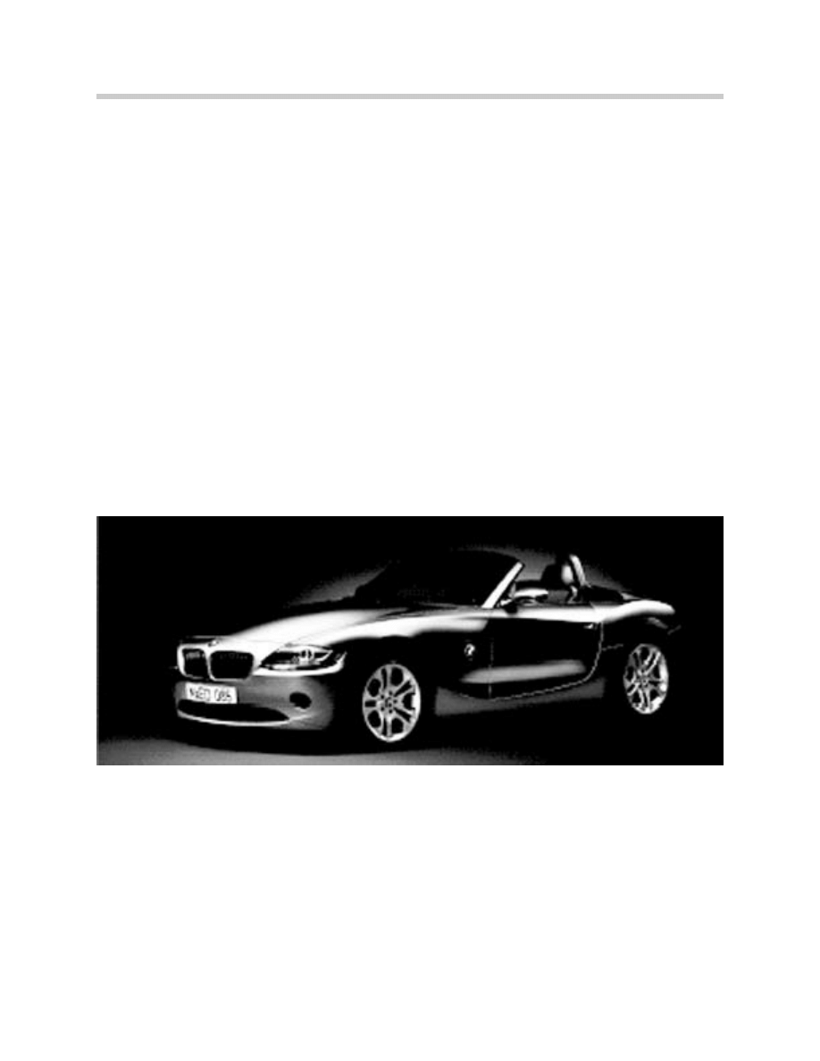
The latest model, the Z4 (development code E85), is being built only as a roadster. There
will be no coupé as there was with the Z3. The 3.0i and the 2.5i versions of the Z4 will both
be fitted with the M54 engine.
With a breathtaking, completely new design and even more sporting driving characteristics,
it is intended to advance to a leading position with regard to dynamism among the com-
petition. A range of equipment that is modern and suited to the market is the basis for suc-
cessful higher placement in comparison to the Z3.
This higher placement is reinforced by the exclusive use of 6-cylinder engines as well as the
new name (the Z3 becomes the Z4). In order to secure market leadership, the E85 features
numerous technical gems, whereby the soft-top and audio systems were assigned partic-
ular attention during development; the Z4 is to be the "best in each class."
Different lines of equipment and the offer of virtually all special equipment that has so far
been reserved for higher series (including High navigation with folding monitor) complete the
image of the E85 as a premium model.
Alongside its breathtaking design in a completely new language of shape, the E85 also fea-
tures a variety of technical innovations:
- Engine bonnet made of aluminum
- Completely new soft-top design with Z folding
- Soft-top rear window made of glass
- Top HiFi audio system with Carver woofers
- Engine Sound System MSS (only 3.0i)
- Emission-free fuel tank
- Electromechanical power-assisted steering (Electric Power Steering EPS)
- Standard tires with runflat tires, no spare wheel
- 6-speed manual gearbox (as of 12/2002)
- 6-speed H-SMG gearbox (as of 04/2003)
5
Complete Vehicle
Design
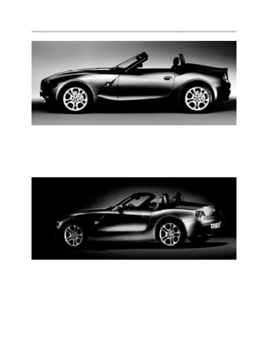
The E85 features all of the proportions that are typical of a roadster: long engine hood, short
rear and short overhangs. Both seats stretch far to the back - almost to the rear axle.
These basic characteristics lend the E85 an extravagant and futuristic appearance The
design does not adopt the same direction as the E65, but rather interprets the values of
sporting character and dynamism by deliberately omitting classical luxury.
The use of "flame surfacing" for the first time makes the new BMW roadster into a breath-
taking pioneer in a new era of design. The mix of curves and straight lines, crossing lines,
concave and convex elements underlines this language of shape. Depending on the angle
of view, the E85 reveals a wide variety of details to the beholder.
In comparison to the Z3, the front is smoother and rounder, but preserves the typical BMW
characteristics of kidney grille and double headlights. The kidney grille has been lowered
into the deforming elements made of yielding foam material. The turn indicator lamps
extend across the entire lower edge of the front headlights (bi-Xenon as special equipment)
up to the side top edge.
The side line continues the roundings of the front with a striking sweep. The front limit line
of the engine bonnet runs across the headlight top edges into the vehicle flanks. There, it
continues over the front mudguard in a curve all the way to the lower edge of the doors,
which it closes off to the rear.
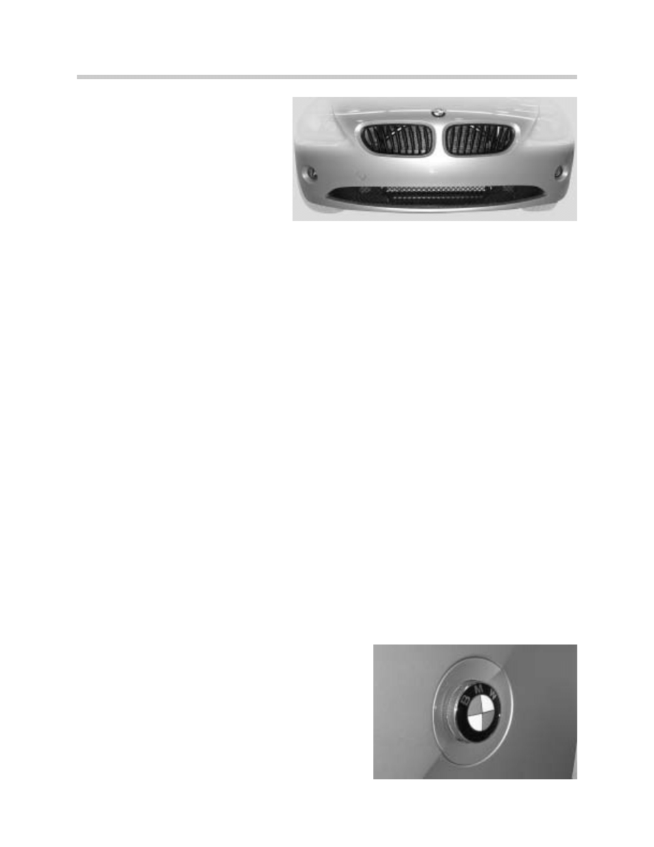
A slanted straight bead in front of the doors adopts the line of the A-pillars. It clearly delin-
eates the front mudguards and is interrupted by a large BMW emblem, surrounded by the
side turn indicator lamps. Although the soft-top lies open in the soft-top compartment, it is
permanently covered and dirt-protected by means of the new Z folding by its own front
third.
6
Complete Vehicle
The highly expressive rear end is kept visually flat by means of the almost horizontal side
lines. Together with the rear lights cut straight at the top and curved at the bottom, the E85
radiates just as much dynamism and activity from the rear as it does from the front.
The centre brake light is inserted beneath the striking cut edge of the luggage compartment
lid. The wheels deployed are exclusively light-alloy wheels, initially with 6 different rim
designs with 16, 17 or 18 inches diameter.
7
Complete Vehicle
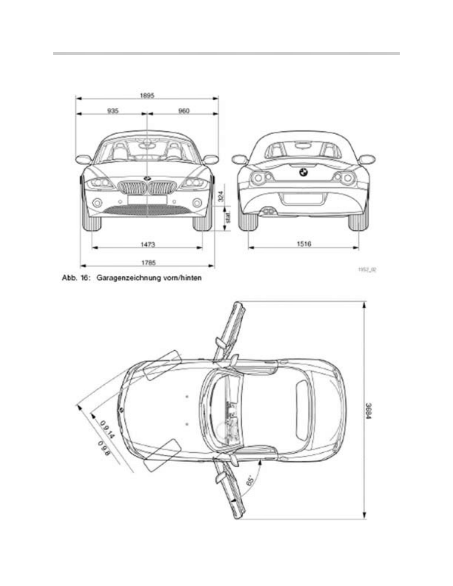
Vehicle Data
8
Complete Vehicle

9
Complete Vehicle
Technical Data
BMW Z4 3.0i (2.5i)
BMW Z3 3.0i
Length (mm)
4086
4050
Width (mm)
1785
1740
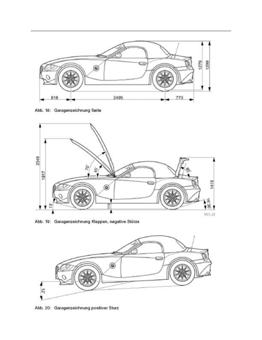
Height (mm)
1299
1293
Wheelbase (mm)
2495
2446
Cylinders/Valves
R6/4
R6/4
Output (HP)
231
(191)
231
At Engine Speed (RPM)
5900 (6000)
5900
Torque (Nm)
300 (245)
300
At Engine Speed (RPM)
3500
3500
0-100 km/h (s)
5.9 (N/A)
6.0
Fuel Consumption (l/100km)
9.2 (N/A)
9.5
Fuel Tank Capacity (l)
55
52
Trunk volume
Top Lowered
Top Raised
240
260
165
165
Rigidity (hz)
19.5
17.0
Rigidity (Degrees/Nm)
14000
7000
Empty Weight (kg)
1331
1360
Emission Compliance
ULEV (LEV)
ULEV
10
Complete Vehicle
Body
A conventional, roadster-specific steel body with bolted side walls (reduced repair effort in
the case of small parking accidents) stands on a completely new sub-frame. Only the
engine bonnet is made of aluminum.
The steel structure of the bodyshell is welded from weight-optimized components and car-
ries an integrated rollover bar. The exterior plate of the A-pillar is additionally reinforced,
which benefits rigidity in the event of a rollover.
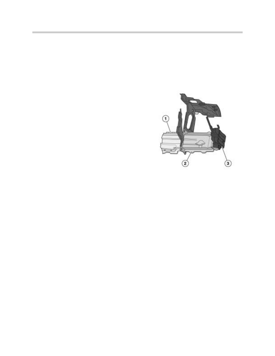
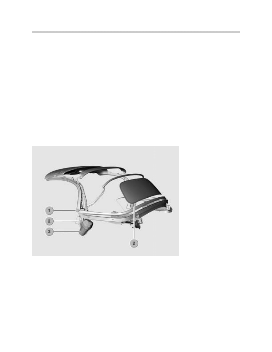
Comparatively long deforming elements (2) are
bolted onto the front side members (1), to which
in turn the bumper system (3) made of reversible
system foam is secured. The deforming ele-
ments are matched to the side members as
regards shape and diameter, and they achieve a
higher level of force than other energy-absorbing
systems. This means that, in the event of a high-
speed crash, they are more effectively involved
in the energy household.
Hood
The bonnet is made of aluminum. It has a service position setting which allows it to be
opened to an angle of approx. 90º. The hinges are made of coated steel. The hood can be
adjusted by means of buffers.
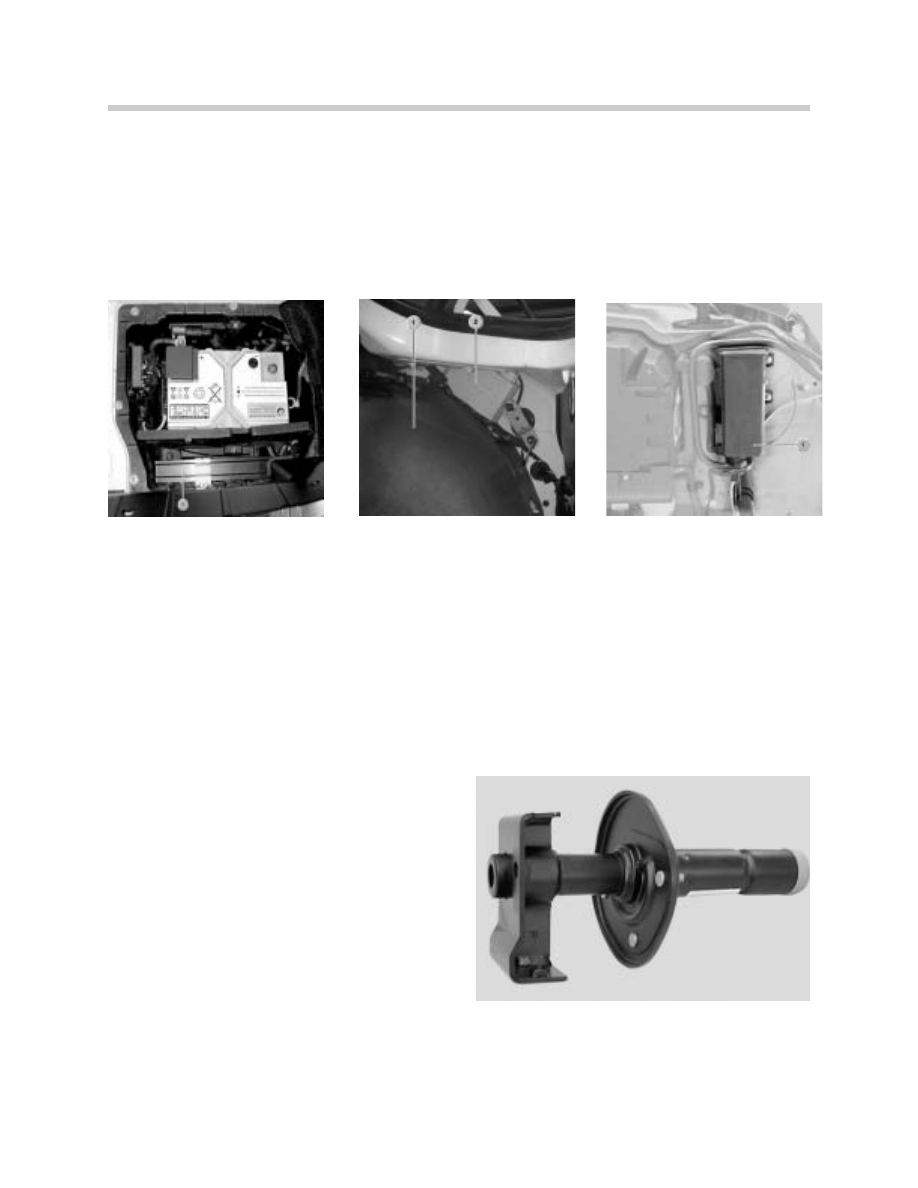
Headlights
The E85 headlights are fitted with halogen bulbs as standard for both the dipped and main
beams. Bi-xenon bulbs are available as an option. The bi-xenon headlights come with
automatic beam height adjustment, while the halogen headlights have manual beam
height adjustment.
There is a completely new procedure for replacing the bulbs. On the E85, the bulbs are only
accessible through a hole in the wheel arch liner.
The headlights are adjusted from inside the engine compartment through the cross-mem-
ber using an Allen key.
The headlight lenses can not be replaced individually. They are permanently glued to the
headlamp unit outer casing.
The headlight beam height positioner can be removed through the open cover when the
headlight unit has been removed. Removal of the headlight beam height positioner involves
threading it through the joint socket. On the dynamic positioner, the connector can be
unplugged; on the manual positioner, the cable has to be cut.
11
Complete Vehicle
Front bumper
The front bumper system consists of:
•
deformation elements
•
aluminum cross-member
•
impact absorbers
•
plastic panel
The individual bumper components can be fitted and removed one at a time in sequence
(sandwich construction).
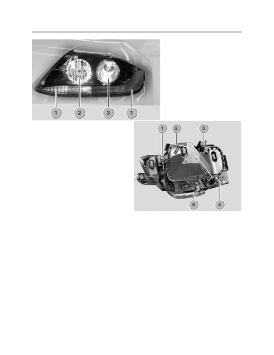
1. Turn Signals
2. High Beam Headlights
3. Low Beam Headlights
1. Vertical Adjustment Actuator
2. Wire Retaining Clip
3. Horizontal Adjuster
4. adjusting Screw
5. Flexible Shaft
12
Complete Vehicle
Plastic panel
The bumper plastic panel is a one-
piece panel that is painted in the body
colour. It clips to the side panels as on
the E65 and is bolted to the front bulk-
head and the underbody. The kidney
grille clips in from the outside.
Service notes
The fog lamps are adjusted by means of the screw that is accessed through the hole above
the fog lamps. The towing lug screws into a tapped hole. As on earlier models, the thread
is protected by a captive cap painted in body colour.
Impact absorber
The impact absorber is bolted onto the cross-member.
Bumper cross-member
The cross-member is bolted onto the deformation elements.
Deformation elements
The steel shell-design deformation elements are bolted onto the left and right engine sub-
frame side-members. By using a cross-section profile that mirrors and is adapted to the
engine subframe members, the deformation elements can absorb a large amount of ener-
gy. In the event of a high-speed impact, the shape and length of the deformation elements
allows them to absorb the energy and protect the welded bodyshell. This substantially
reduces the cost of repairs.
Note:
The bumpers on the US versions prevent damage to the headlamps at collision speeds of
up to 4 km/h. On the US version, the aluminum cross-member has a thicker wall.
Front side panels
The front side panels are made of steel and are
attached to the body by means of bolts. There is
also a side repeater flasher integrated in each side
panel. This lamp is not attached by screws. To be
removed, the side repeater flasher has to be turned
through 90º and can then be taken out.
13
Complete Vehicle
Windscreen
There are three choices of windscreen available:
•
The standard windscreen with green-tinted heat-blocking laminated safety glass
•
The optional windscreen with green sun visor strip
•
The optional windscreen with green sun visor strip and rain/light sensor
Door mirrors
The door mirrors are screw mounted at three points.
The following types of mirror glass are available as optional extras:
•
Electrochromatic mirror glass
•
Convex mirror glass
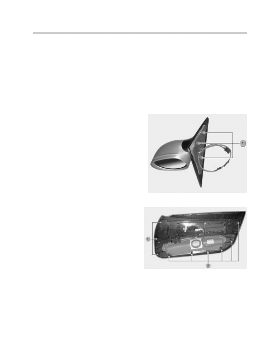
The mirror glass is attached to the mirror posi-
tioning motor by a bayonet fixing (1). In order to
access that fixing, a small cover has to be
unscrewed. The mirror glass can then be
removed. The painted mirror body can also be
removed separately. This involves first remov-
ing the mirror glass and then unscrewing the
positioning motor as well. The push-fit mirror
body can then be pulled off.
Door trim panel
The door trim panel is attached to the door by
screws, clips and catches.
There are four fixing screws:
•
One behind the airbag symbol
•
One behind the door release grommet
•
Two behind the door pull clasp
In addition there are 9 clips. There is sound
insulation material glued behind the door trim
panel.
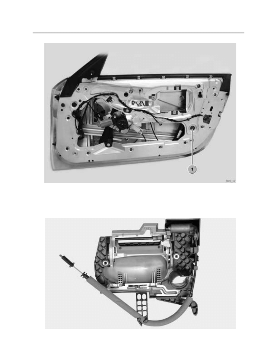
Window regulator/door window glass
The E85 uses a cable-operated window regulator. There are slots, tapers, adjusting and
locking screws provided for adjusting the window glass on the X, Y and Z axes.
The door window glass is made of non-laminated safety glass.
1. Grey Clips
2. White Clips
14
Complete Vehicle
Handle/lock
The exterior handle can be removed by means of a special tool (same design as E39).
The lock and the servo motor form a single unit.
15
Complete Vehicle
Interior
The E85 is available with the following interior trim options:
•
"Free Spirit" recognizable by fabric seats
•
"Active Sports" recognizable by fabric/leather combination seats
•
"Oregon Leather" full leather seats
•
"New England Full Leather" full leather seats with decorative seam in the center
•
"Black Artificial Leather" (US only)
Seats
The basic seat in the E85 is essentially the same from a technical point of view as the basic
seat in the E46. The design has been has been modified, however.
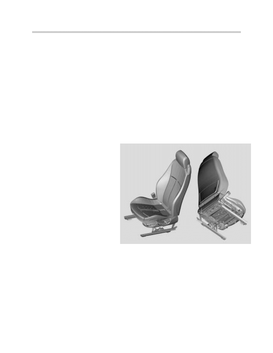
Basic seat (electric)
The following features are new:
•
The backrests of the basic seats
do not fold down.
•
The backrest frame is a
completely new design. It is
slimmer, higher and lighter. The
backrest upholstery and the
cover are also new.
•
The new head restraints have a
smaller range of adjustment.
•
The seat base has been lowered
by 10 mm compared with the
E46 in order to achieve a typical
roadster sitting position.
The following fabric options are offered:
•
Artificial leather: basic seat for US version
•
Fabric/artificial leather combination: basic seat for ECE version (Free Spirit)
•
Fabric/leather combination: optional extra (Active Sports)
•
Oregon Leather: standard on 3.0i model, optional extra on other models
•
Gloss leather: "Extended Leather Trim" option (New England leather)
On the US version, the ISOFIX is fitted as standard.
Other optional extras are the electric seat adjustment and the seat heating for driver's seat
and passenger seat.
16
Complete Vehicle
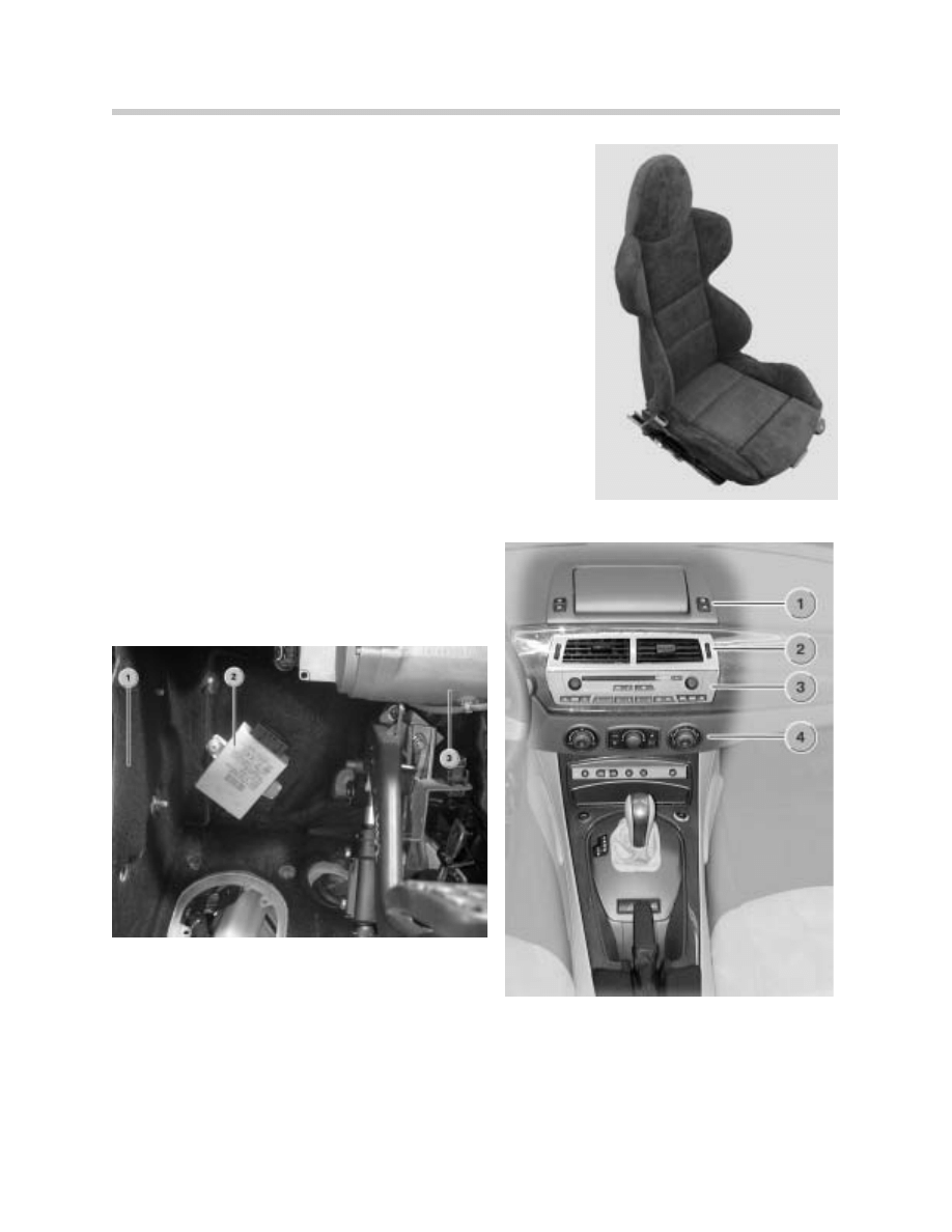
Sport Seat
The M Sports Seat is available as an option.
Control unit locations in passenger compartment
The following Control Units are located in the passenger
compartment:
•
Instrument Cluster
•
Light Switch Center
•
CID
•
IHKA
•
EWS
•
EPS
•
Steering Angle Sensor
•
Center Console Switch Center
•
Seat Module
•
CVM
•
DSC Sensor
•
GM V
•
Mirror Folding Module
1. CID
2. Air Vent
3. CID Control Panel
4. IHKA
1. A-Pillar Trim Panel
2. EWS Control Unit
3. Electric Servo Motor unit for EPS
17
Complete Vehicle
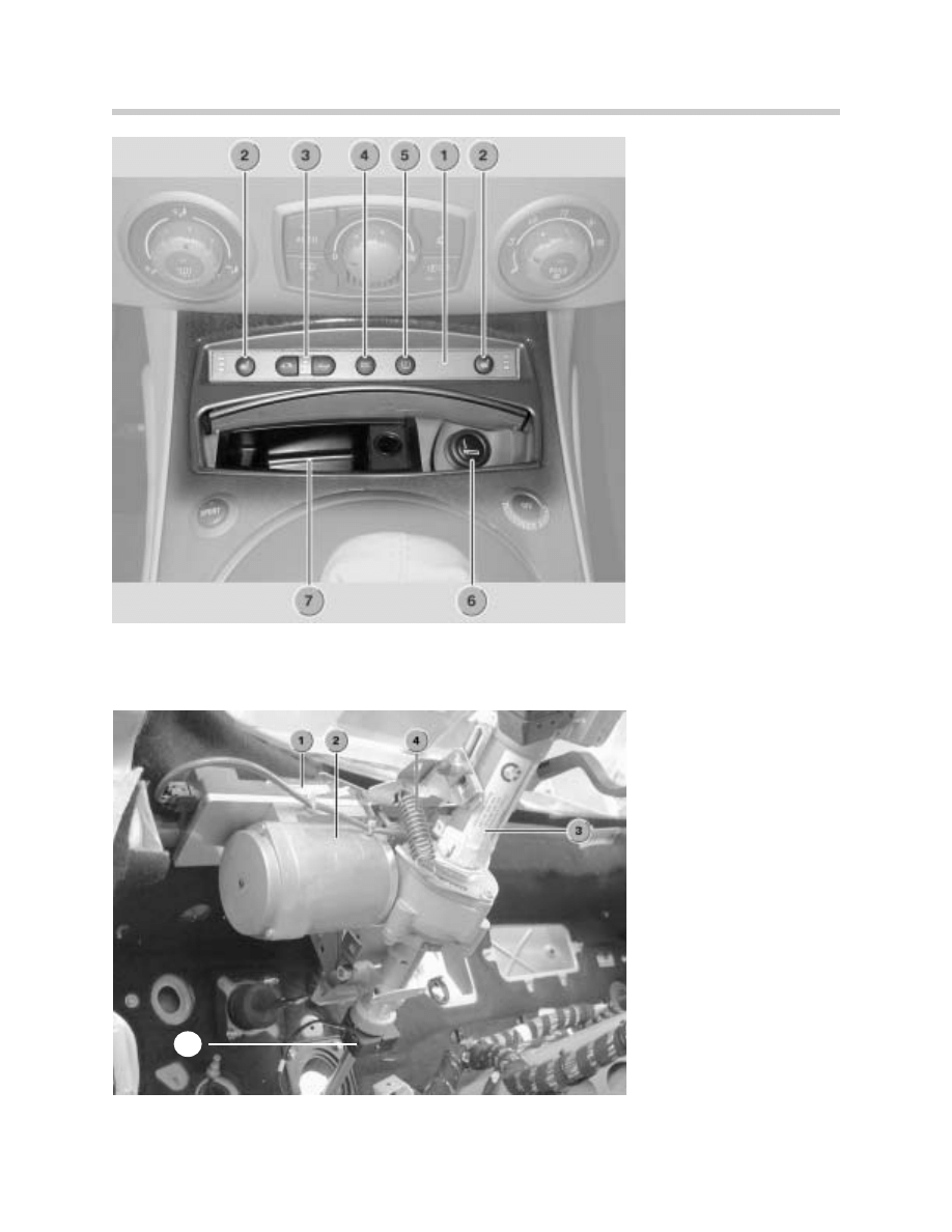
1. Center Console Switch Center
2. Left/Right Seat Heater Buttons
3. Soft-Top Controls w/ LEDs
4. DSC Button
5. RPA Button
6. Cigarette Lighter
7. Ashtray
1. EPS Control Unit
2. Electric Servo Motor Unit
3. Steering Column
4. Mass Balance Spring
5. Steering Angle Sensor
5
18
Complete Vehicle
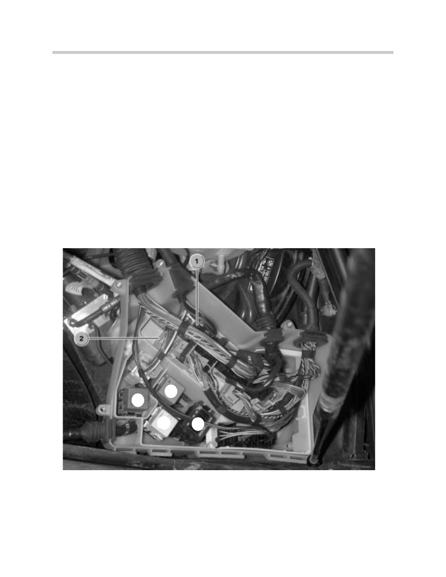
Engine compartment Control Units
As usual, there are a number of important control units in the engine compartment. The
electronics box on the left at the front contains the DME control unit. Depending on the
equipment option chosen, it may also house the EGS (electronic gearbox control) or the
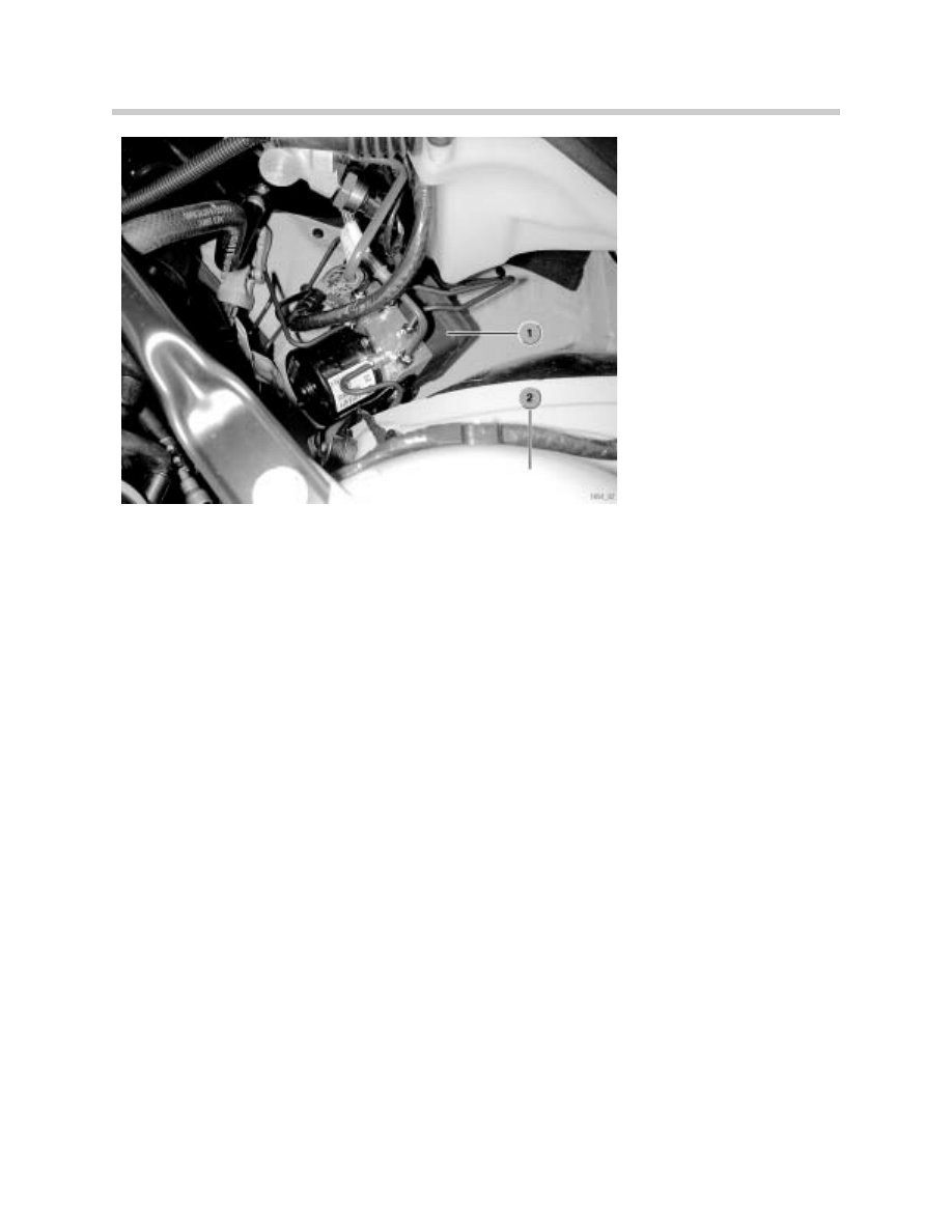
SMG (sequential/manual gearbox control) unit. The DSC (Dynamic Stability Control) unit is
attached near to the left wheel arch.
A new feature as compared with the Z3 are the suspension-strut mounting cross-braces
bolted between the wheel arches and the engine bulkhead.
Locations of control units in engine compartment
The control units of the following important systems are fitted in the engine compartment
of the Z4:
•
DME (digital engine electronics)
•
EGS (electronic gearbox control)
•
SMG (sequential/mechanical gearbox control)
•
DSC (Dynamic Stability Control)
1. DME
2. EGS/SMG Control Unit
3. Back-up Light Relay
4. DME Relay
5. Fuel Injector Relay
6. Underhood fuses 1-5
3.
6.
4.
5.
19
Complete Vehicle
E85 Soft-top
The E85 is available with two soft-top options - manual and fully automatic.
A large number of magnesium and aluminum components have been used in the soft-top
frame which combine lightness with safety in the event of an accident. The low soft-top pro-
file offers sufficient headroom.
The natural glass rear window provides optimum transparency. The high-quality impression
is retained regardless of the age of the rear window as it no longer gets scratched. The elec-
tric rear window heater ensures the window does not mist over.
The "Z" folding action means that the front roof bow simultaneously acts as the stowage
compartment cover when the top is lowered. This further simplifies operation of the soft-
top as there is no separate stowage compartment cover to be moved. Consequently, there
is no need for a soft-top cover (as on E46 Convertible) or a tonneau (Z3).
Manual soft-top
The central soft-top latch for locking it to the windscreen top rail is operated by one hand.
This enables the soft-top to be locked easily and ergonomically with one hand.
1. DSC Control Unit
2. Wheel Arch
20
Complete Vehicle
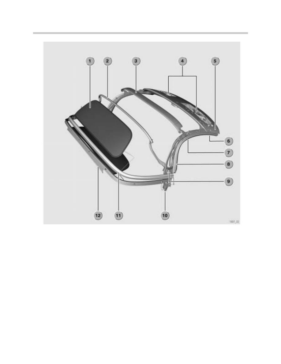
Components
1. Rear Window (Glass)
7. Center Pillar Section
2. Corner Rood Bow (Steel)
8. Main Pillar Section
3. Center Roof Bow (Aluminum)
9. Main Bearing with Hardtop locating socket
4. Soft Top Latch for Locking to windshield rail
10. Hydraulic Positioners (Automatic top only)
5. Front roof Bow (Magnesium)
11. Seal Soft top Stowage Compartment
6. Front Pillar Section
12. Soft top Bottom Rail (Aluminum)

21
Complete Vehicle
Soft Top Fabric
The soft-top fabric consists of Twillfast RPC (as on E46/C) and is replaceable.
The rear window can only be replaced as part of the soft-top fabric.
Rear window
The rear window is made of natural glass. The rear window is attached to the soft-top fab-
ric by PU foam (as on E46/C) and cannot be replaced separately.
Lowering the soft top
The soft-top is released from the windscreen top rail by hand from the inside using the lock-
ing/release handle. The soft-top is then stowed in the stowage compartment and locked
in place by the stowage compartment catch. The front roof bow acts as the stowage com-
partment cover when the soft-top is lowered.
Raising the soft-top
Pressing the button in the rear centre trim panel releases the stowage compartment catch
and the soft-top moves upwards slightly by the action of the gas dampers. The soft-top is
raised up to the windscreen top rail by hand. The soft-top is locked to the windscreen top
rail by hand from the inside using the locking/release handle.
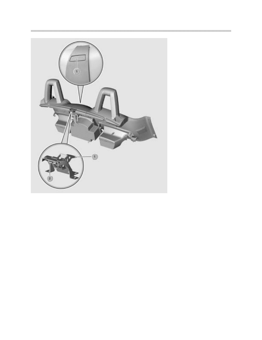
Stowage compartment catch
When stowed in the stowage compartment, the soft-top is held in place by a locking mech-
anism. The stowage compartment catch is located in the centre of the stowage compart-
ment.
To lock it in place, the manual soft-top has to be pushed down lightly into the stowage com-
partment by hand. The soft-top centre latch (on the front roof bow) then engages in the
stowage compartment catch (2).
Releasing the stowage compartment catch:
Pressing the stowage compartment catch release button (1) releases the catch and the
soft-top moves upwards slightly (by the action of the gas dampers on the main bearings).
The release button (1) is located on the rear centre trim panel between the two seats and
is accessible from inside the vehicle.
22
Complete Vehicle
Service notes:
The manual soft-top is available in black only and without inner lining. The soft-top is
designed in such a way that it does not have to be removed in the winter.
Ordering spare parts:
The following spare parts can be ordered (same as E46/C):
•
Complete soft-top (fabric, inner lining and frame)
•
Fabric only
•
Frame only
Adjusting the soft-top:
Correct adjustment is provided by adjusting shims. There are factory-fitted adjusting shims
under the fixing bolts (M8) on the B-pillar. They ensure the correct lateral gap between the
soft-top and the body. When a new soft-top is fitted, the adjusting shims have to be
refitted.
Fully automatic soft-top
1. Mechanism and Release Button
2. Stowage Compartment Catch
23
Complete Vehicle
The fully automatic soft-top, like the standard soft-top, consists of magnesium and alu-
minum components.
The soft-top lowers and raises fully automatically by means of electrohydraulic servo units
that control the primary soft-top movements. The soft-top/windscreen top rail locks are
operated by an electric motor.
The soft-top is raised and lowered by pressing the soft-top switch located between the
gear lever and the ash tray - no additional manual operations are required.
The inner lining provides a neat, coupé-style interior effect, and significantly improves the
soft-top acoustics and heat insulating properties.
The fully automatic soft-top is available as an optional extra.
System overview
The hydraulic pump unit is mounted on the left soft-top main bearing.
Hydraulic pump unit
The hydraulic pump unit consists of an oil reservoir with an integral pump. The pump is dri-
ven by a DC reversing motor. All hydraulic valves are integrated in the hydraulic pump unit.
Method of operation:
1. Main Bearing
2. Hydraulic Servo Unit
3. Hydraulic Pump Unit

24
Complete Vehicle
To change the direction of movement of the folding soft-top, the direction of rotation of the
hydraulic pump motor is reversed. The hydraulic pump only operates while the soft-top is
being moved.
The operation of the pump and locking mechanism are controlled by the CVM IV control
unit as required on the basis of the soft-top switch setting.
A temperature sensor protects the hydraulic pump unit against overload. There is a tem-
perature sensor fitted to the hydraulic pump unit (similar to E46/C). At a temperature of 105º
Celsius the pump is prevented from operating in order to protect the hydraulic system from
damage. The soft-top can then only be operated manually.
There is no facility for topping up the hydraulic fluid on this sealed hydraulic system, nor is
it necessary. The hydraulic system has a self-bleeding function which is activated by repeat-
ed operation. In order to replace the hydraulic pump unit, the soft-top frame has to be
removed.
Hydraulic servo units
The folding soft-top is moved in two directions for lowering and raising by two double-
action hydraulic servo units. The hydraulic servo units can only be replaced in conjunction
with the soft-top frame as a whole.
There is one hydraulic servo unit on each side of the soft-top frame (in the main pillar) on
the main bearings. The hydraulic pump unit is attached to the left hydraulic servo
unit.
Preconditions for raising and lowering the soft-top
Before the soft-top can be moved, the following preconditions must be met:
1. Neither window detected as closed by the basic module
2. Vehicle stationary (road speed < 5 km/h)
3. No hardtop fitted
4. Ignition key position at terminal R at least (except for Easy Open/Close function)
5. System test reports no faults
6. No short circuit and no circuit break present
7. Outside temperature is above minimum limit
Preconditions 1 to 7 must be satisfied simultaneously.
Lowering the soft top

25
Complete Vehicle
Sequence:
1. Windows are lowered (window regulators are operated for 1.5 seconds if a closed win
dow is detected)
2. Soft-top is released from the windscreen top rail
3. Soft-top is folded backwards
4. Soft-top is stowed in stowage compartment and locked in place
5. Locking latches are retracted while pump is still running
6. Red LED goes out
7.Windows are raised (2 seconds after soft-top locks in position)
Raising the soft top
Sequence:
1. Windows are lowered (window regulators are operated for 1.5 seconds if a closed win
dow is detected)
2. Locking latches are extended and the stowage compartment catch is released
3. Soft-top is lifted out of stowage compartment
4. Soft-top is raised forwards
5. Locking latches engage in windscreen top rail
6. Locking mechanism is activated, moves to "LOCKED" position and stops on reaching
the limit switch
7. Red LED goes out
8.Windows are raised (2 seconds after soft-top locks in position)
Note:
If the soft-top button is released while the raising or lowering sequence is still in progress,
the movement of the soft-top comes to an immediate halt. Because the drive system does
not lock, the soft-top is then held only by the inherent resistance within the mechanism and
the hydraulic servo units.
Pressing the button again restarts the interrupted movement.
Easy Open function
An automatic sequence of operations for lowering the soft-top can be activated using the
ignition key in the driver’s door.
Sequence:
1. Insert ignition key in driver's door lock
2. Turn key anti-clockwise and hold. The basic module immediately sends the "Easy Open"
signal to the soft-top module.
3. The window regulators are then operated by the CVM control unit within 1.5 seconds.
Windows are lowered
4. Remaining sequence as for "Lowering the soft-top", steps 2 to 7

26
Complete Vehicle
5. Remove ignition key from door
The Easy Open function is not possible after terminal R.
Easy Close function
An automatic sequence of operations for raising the soft-top can be activated by locking
the driver's door.
Easy Close sequence:
1. Insert ignition key in driver's door lock
2. Turn key clockwise and hold. The basic module immediately sends the "Easy Close"
signal to the soft-top module
3. Remaining sequence as for "Raising the soft-top", steps 2 to 7
4. The window regulators are then operated by the CVM control unit within 1.5 seconds.
Windows are closed.
5. Remove ignition key from door
Note:
If the signal from the soft-top module IV is not received, the basic module activates the
automatic "Close All" function. The Easy Close function is not possible after terminal R.
Emergency actuator
If the electrics or hydraulics fail, the soft-top can be raised/lowered by means of the emer-
gency actuator.
To raise the soft-top using the emergency actuator, the following procedure must be fol-
lowed:
- Open bypass circuit on hydraulic pump unit by pulling cable.
- Release soft-top stowage compartment catch by pulling cable.
- Raise soft-top to windscreen top rail by hand.
- Engage windscreen top rail lock using Allen key.
For lowering the soft-top with the emergency actuator, the procedure is reversed.
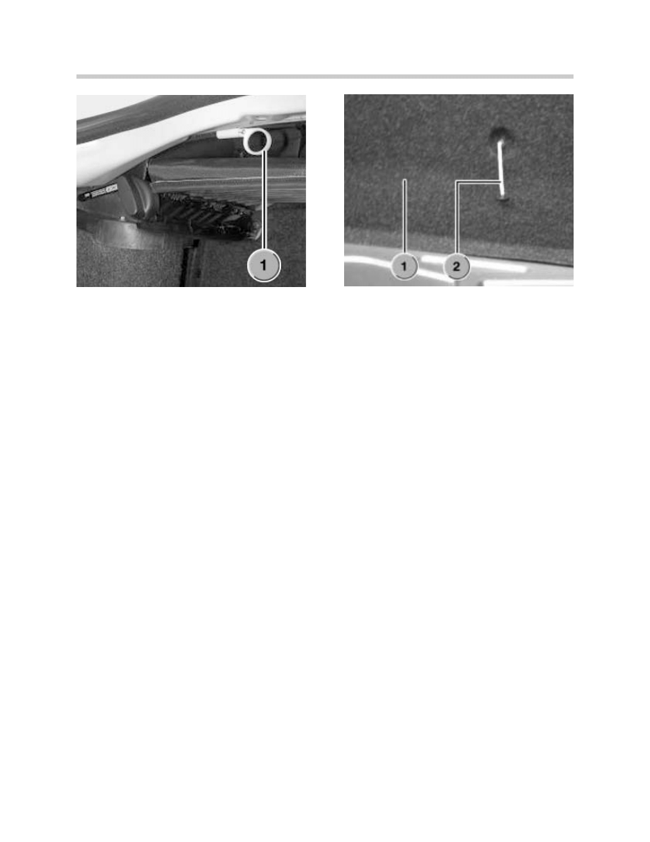
Opening bypass circuit on hydraulic pump unit:
In the boot on the left-hand side below the soft-top stowage compartment base there is a
release cable with a plastic pull handle. The plastic pull handle is pulled out as far as it will
go and then locked in that position by turning it through 90º. This opens a bypass circuit
in the hydraulic pump unit. The soft-top can then be moved by hand.
27
Complete Vehicle
Emergency stowage compartment catch release
The soft-top stowage compartment catch must then be released. This involves pulling the
release cable on the rear boot trim panel. The soft-top stowage compartment catch then
disengages. The release cable is on the boot bulkhead. Pulling the release cable handle
from inside the boot releases the soft-top stowage compartment catch. The soft-top can
then be raised up to the windscreen top rail by hand.
Operating the windscreen top rail lock manually:
To lock the soft-top to the windscreen top rail, the plastic trim on the front roof bow must
be removed. Below the plastic trim panel is a socket-head bolt. Using the Allen key sup-
plied in the vehicle toolkit, the windscreen top rail lock can then be locked or unlocked man-
ually.
Adjustment after soft-top removal/replacement:
There are factory-fitted adjusting shims under the fixing bolts (M8) on the B-pillar. Those
adjusting shims ensure the correct lateral gap between the soft-top and the body.
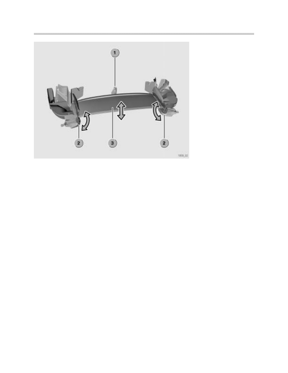
Variable-position soft-top stowage compartment base
The mechanism of the soft-top stowage compartment base consists of twin hinges with
adjuster handles and gas dampers.
1. Emergency Actuator Release for Hydraulic Unit
1. Trunk Trim Panel
2. Cable Release for Stowage Compartment
28
Complete Vehicle
The stowage compartment base is at its lowest position when the soft-top is stowed. When
the soft-top is raised, the variable-position soft-top stowage compartment base (3) can be
manually raised to the upper position from inside the boot. This provides additional boot
space so that bulky items such as drinks crates, golf bags, etc. can then be carried. The
soft-top can only be lowered when the stowage compartment base is at its lowest position.
So that the position of the stowage compartment base can be automatically detected,
there is a microswitch (1) fitted to it.
The stowage compartment base can be moved to the upper or lower position by turning
the adjuster handles (2). Gas dampers incorporated in the two stowage compartment base
mechanisms hold the stowage compartment base at the respective limits of movement.
Index Explanation
Hardtop
The hardtop on the E85 is similar in design to the E36/7 version.
The hardtop consists of the following components:
•
Hard shell with bolt-on spoiler
•
Interior trim (inner lining)
•
Centering bolts/centering and securing bolts
•
Attachment locks with mechanism
•
Covers for centering and securing bolts
•
Special fitting tool
Wind-break
1. Microswitch
2. Adjuster Handles
3. Stowage Compartment Base
29
Complete Vehicle
The wind-break substantially reduces the draught in the passenger compartment when the
soft-top is down. The wind-break (2) fits into locating recesses between the two roll-over
bars. The locating recesses are integrated in the rollover bar trim panels. The wind-break
can be removed when not in use and stored in the boot lid.
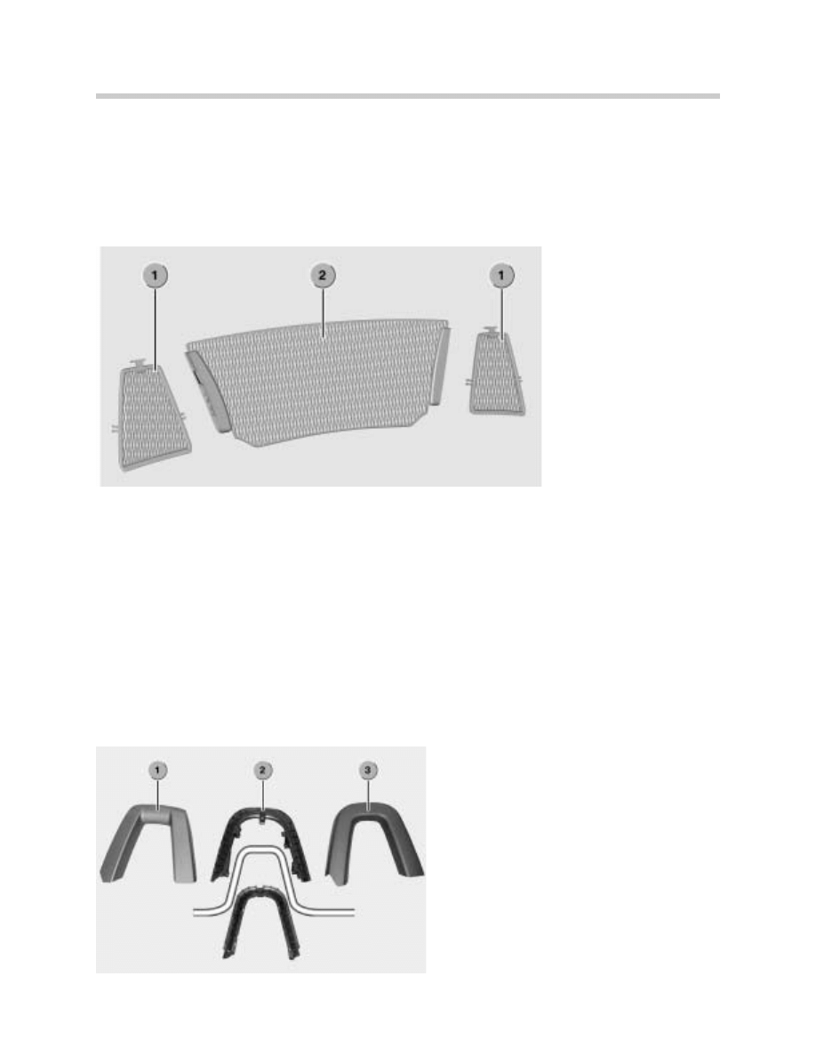
Roll-over bar trim panels
There are locating recesses for the wind-break integrated in the roll-over bar trim panels.
The roll-over bar trim panels contain mesh inserts (1).
Each roll-over bar trim panel consists of two parts which are snap-fitted onto the roll-over
bars.
Note:
The wind-break can be ordered as an optional extra with the vehicle.
As the fixings for the wind-break are integrated in the roll-over bar trim panels, if the wind-
break is fitted at a later date, the standard roll-over bar trim panels must be replaced with
ones that incorporate the wind-break fixings.
Trunk
1. Mesh inserts for Roll bars
2. Mesh insert In-Between
Roll Bars
1. Front Trim Panel
2. Impact Absorber
3. Rear Trim Panel
30
Complete Vehicle
The following control units are located in the boot on the E85:
•
HiFi amplifier/Top HiFi amplifier (DSP amplifier)
•
AMPS compensator (USA only)
•
PDC control unit
•
Fuel tank leakage diagnostic module (USA only/boot under vehicle)
Rear bumper
The rear bumper system consists of:
•
2 impact dampers (US version)
•
One cross-member
•
2 impact absorbers
•
A plastic panel
Impact dampers (US version)
The impact dampers to which the bumper
cross-member is attached collapse by about
30 mm into the chassis side members in the
event of an impact.
1. HiFi Amplifier
1. DM-TL
1. Wheel Arch Trim
2. PDC Control Unit
31
Complete Vehicle
Plastic panel
The thermoplastic bumper panel is painted in the body colour.
The license plate holder is attached to the plastic bumper panel by two dome-head screws
designed for use with thermoplastic components. The cut-out for the towing eye is cov-
ered by a captive cap painted in body colour.
Park Distance Control (PDC)
PDC is available as an optional extra on the EU models. The 4 PDC sensors are push-fit-
ted in the rear plastic bumper panel. There are 8 cable clips provided for routing the wiring.
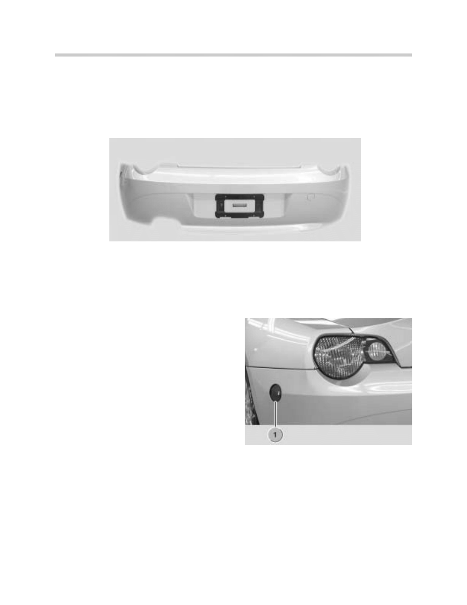
Sidemarkers (US)
In addition to the differences already referred to
regarding the aluminum cross-member with
impact dampers and impact absorbers, the
plastic bumper panel of the US version has
two integral sidemarker lamps (1). They are illu-
minated by LEDs.
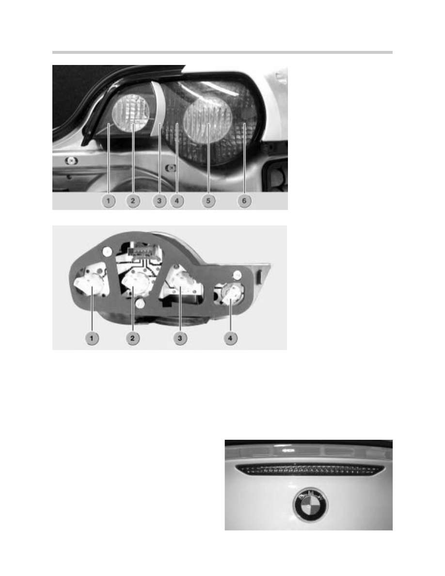
Rear light clusters
The rear light clusters are attached to the rear end panel from the outside by three bolts (6
mm). Between the light cluster and the body there is a seal. The rear light clusters combine
the tail light, brake light, reversing light, rear fog lamp (EU), reflector and direction
indicator functions.
In the centre of the rear light cluster there is a body-colour decorative strip. It is attached to
the light cluster lens by a double-sided adhesive strip.
The bulbs are replaced from inside the boot.
32
Complete Vehicle
Rear light cluster surround
Around the rear light clusters is a surround painted in body colour. It is attached to the rear
light cluster by means of retaining lugs and screws to the body together with the light
cluster.
Third brake light
The third brake light is integrated in the boot
lid on the E85. It consists of an LED array
that can only be replaced as a complete
unit.
1. Reflector
2. Back-up Light
3. Decorative Strip
4. Tail Light/Brake Light
5. Turn Signal Light
6. Tail Light/Brake Light
1. Tail Light/Brake Light
2. Turn Signal Light
3. Tail Light/Brake Light
4. Back-up Light
Document Outline
- Main Menu
- E85 Complete Vehicle
- E85 BodyShell
- M54 Engine
- MS45 DME Part 1
- MS45 DME Part 2
- MS45 DME Part 3
- MS45 DME Part 4
- E85 Driveline
- E85 Chassis Dynamics
- E85 Heating and Air Conditioning
- E85 Power Supply
- E85 Adv.Safety Electronics
- E85 Driver Information
- E85 Central Body Electronics
- E85 Communications
- E85 Updates
Wyszukiwarka
Podobne podstrony:
01 E83 Complete Vehicle
01 E60 M5 Complete Vehicle
01 E63 64 Complete Vehicle
E65 Complete Vehicle (Part 2)
bmw SIB 23 01 04 complete
E65 Complete Vehicle (Part 1)
1 M3 Complete Vehicle
M5 Complete Vehicle
(not complete) [Concord][Armor at War Mini 7515] Stryker Interim Armored Vehicle
TD 01
Ubytki,niepr,poch poł(16 01 2008)
01 E CELE PODSTAWYid 3061 ppt
01 Podstawy i technika
lecture3 complexity introduction
01 Pomoc i wsparcie rodziny patologicznej polski system pomocy ofiarom przemocy w rodzinieid 2637 p
zapotrzebowanie ustroju na skladniki odzywcze 12 01 2009 kurs dla pielegniarek (2)
01 Badania neurologicz 1id 2599 ppt
01 AiPP Wstep
więcej podobnych podstron