
Initial Print Date:1/03
Revision Date:
Subject
Page
Purpose of the System ........................................................................3
Acceleration Sensors ........................................................................... 6
Steering Angle Sensors ....................................................................... 6
Control Module .....................................................................................7
Program Switch ....................................................................................7
Road Speed Input .................................................................................8
Solenoid Controlled Dampers ...............................................................8
Basic Damper Operation ......................................................................9
E38 Damper Operation .........................................................................10
E31/E32 Damper Operation .................................................................11
Electronic Damper Control Functions ................................................14
Table of Contents
Electronic Dampening Control (EDC)

2
Electronic Dampening Control
Model:
E31 850i, 850Ci, 850CSi, 840i 1991-1997
E32 750iL, 735i/iL, 740i/iL 1988-1994
E38 750iL, 740i/iL from 1995-2001
Production: All with EDC
Objectives:
After completion of this module you should be able to:
•
Identify EDC System Components
•
Locate EDC System Components
•
Understand EDC System Operation

3
Electronic Dampening Control
Purpose of the System
The EDC III is a fully automatic adjusting damper control system available on the E31, E32
and E38 vehicles. It also allows the driver to choice of two damping programs (comfort and
sport)
Conventional non-adjustable systems have damper (shock absorber) settings which pro-
vide an acceptable damping action over as wide of range of speeds and loads as possible.
This means a compromise
between a high standard of ride comfort on one hand, and a margin of safety on the other.
Modern technology enables this trade off to be resolved with variable damping, and this
principle has been adopted on the EDC III system.
The system uses various input parameters directly relating to road condition, load on the
car and driving style to select one of three damping characteristics, (soft, medium or hard).
The result is optimum damping over a wide range of speeds and loads, and definite gains
in both ride comfort and safety.
EDC III is a further development of the variable damping systems already used on BMWs
in other markets.
The purpose of any damping force adjustment is to reduce oscillations as perceived by the
car’s occupants, without affecting either handling or driving safety.
This is achieved by continuously matching the damping force to road conditions, vehicle
load and driving style.
4
Electronic Dampening Control
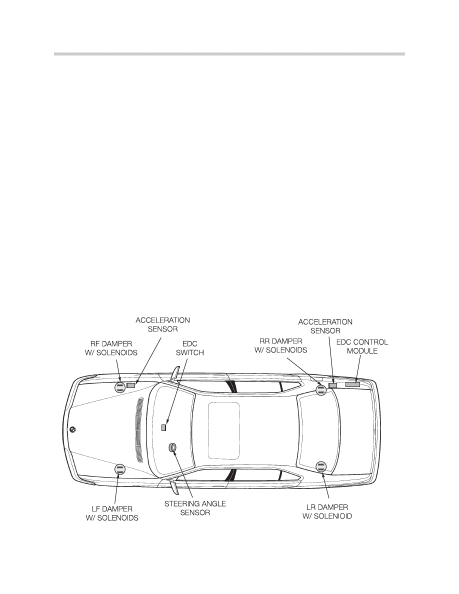
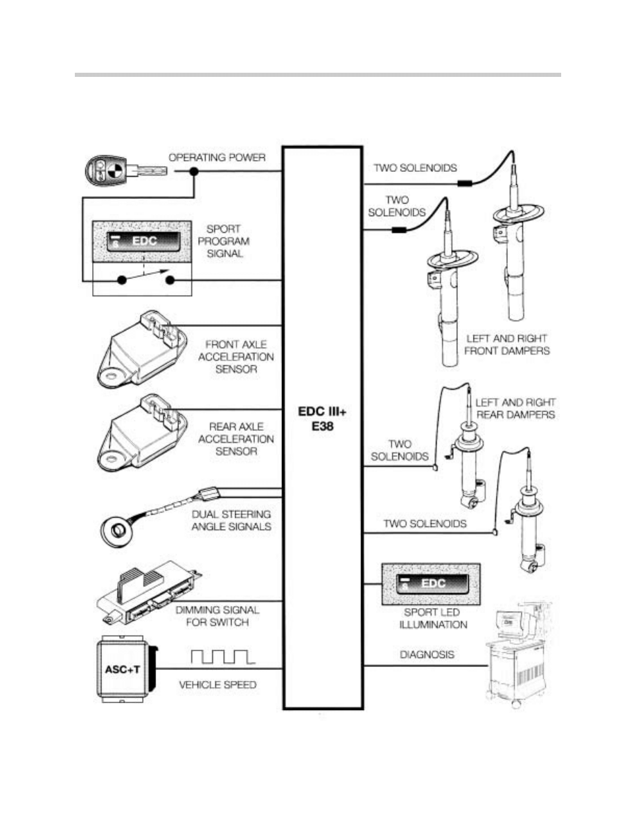
System Components E38
The EDC system on the E38 consists of the following components:
• F
Frro
on
ntt--a
ax
xlle
e a
ac
cc
ce
elle
erra
attiio
on
n s
se
en
ns
so
orr -- This is installed on the right side of the wheel
housing, close to the right-hand upper spring strut mount.
• R
Re
ea
arr--a
ax
xlle
e a
ac
cc
ce
elle
erra
attiio
on
n s
se
en
ns
so
orr - This is installed on the right rear wheel arch, on
top of the spring strut mount
• E
ED
DC
C IIIIII c
co
on
nttrro
oll m
mo
od
du
ulle
e .. Mounted on right side of trunk. (Behind Glovebox from
99 Model Year)
• S
Stte
ee
erriin
ng
g a
an
ng
glle
e s
se
en
ns
so
orr -- On lower section of steering column
• S
So
olle
en
no
oiid
d v
va
allv
ve
es
s -- Integrated in the strut housing.
• P
Prro
og
grra
am
m s
sw
wiittc
ch
h -- Located on dash in center below IHKA panel
5
Electronic Dampening Control
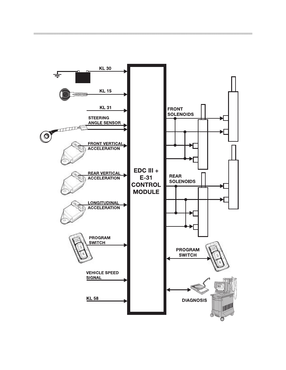
System Components E31/E32
The EDC system on the E32/E31consists of the following components:
• F
Frro
on
ntt--a
ax
xlle
e a
ac
cc
ce
elle
erra
attiio
on
n s
se
en
ns
so
orr -- This is installed on the right side of the wheel
housing, close to the right-hand upper spring strut mount.
• R
Re
ea
arr--a
ax
xlle
e a
ac
cc
ce
elle
erra
attiio
on
n s
se
en
ns
so
orr -- This is installed on the right rear wheel arch, on
top of the spring strut mount.
• E
ED
DC
C IIIIII c
co
on
nttrro
oll m
mo
od
du
ulle
e a
an
nd
d p
po
ow
we
err rre
ella
ay
y - Both units are mounted in trunk on
right side.
• L
Lo
on
ng
giittu
ud
diin
na
all a
ac
cc
ce
elle
erra
attiio
on
n s
se
en
ns
so
orr -- On the left rear wheel arch.
•
S
Stte
ee
erriin
ng
g a
an
ng
glle
e s
se
en
ns
so
orr -- On the steering column (similar component on the E31,
E32 but not interchangeable)
• S
So
olle
en
no
oiid
d v
va
allv
ve
e -- Two valves are mounted at the base of each strut assembly.
• P
Prro
og
grra
am
m s
sw
wiittc
ch
h -- Located on center console.
6
Electronic Dampening Control
Components
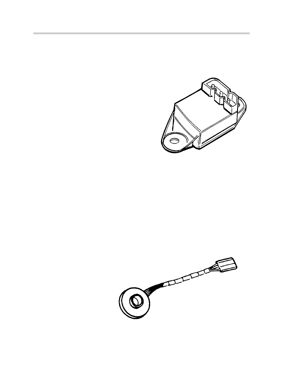
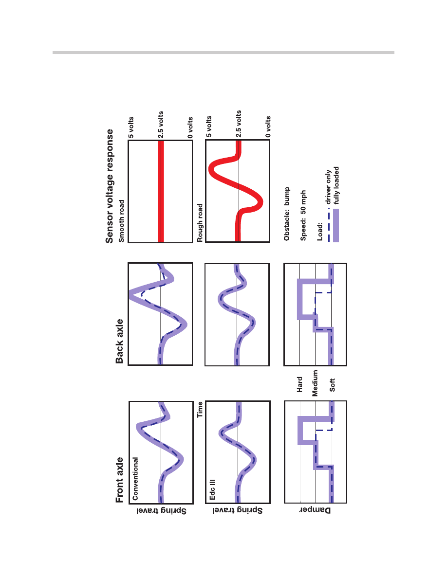
Acceleration (Motion) Sensors
There are three acceleration sensors: one each for
the front and rear axles (vertical motion), and one
for forward/aft motion. All sensors are solid state,
piezo ceramic elements. Vehicle movement on the
sensors is converted into an electric signal. The
control module uses these inputs to detect road
surface condition, vehicle loading and degree of
motion. The loading of the vehicle influences ver-
tical motion and is therefore detected by the sen-
sors.
The E38 acceleration sensors are identical to the
E31/E32 sensors, the longitudinal sensor has
been deleted on the E38. The dynamic longitudi-
nal forces on the vehicle are calculated from the
inputs of the front wheel speed sensors.
The following inputs are used to detect dynamic forces acting on the vehicle;
• V
Ve
errttiic
ca
all a
ac
cc
ce
elle
erra
attiio
on
n
• F
Fo
orre
e a
an
nd
d a
afftt a
ac
cc
ce
elle
erra
attiio
on
n
• S
Stte
ee
erriin
ng
g w
wh
he
ee
ell a
an
ng
glle
e
• V
Ve
eh
hiic
clle
e rro
oa
ad
d s
sp
pe
ee
ed
d
Steering Angle Sensor
The steering angle sensor is
identical for all vehicles The
rotating double potentiometer
provides two variable resis-
tance signals for turn recogni-
tion. The EDC control module
used this input to increase the
damping rate when corning.
7
Electronic Dampening Control
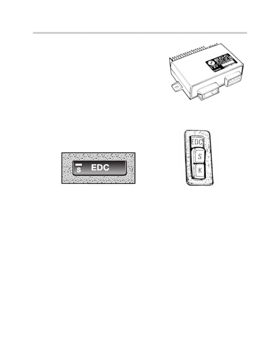
Control Module
One basic control module is used for the E38.
Selecting the proper damping curves is carried out via
the DISplus or GT-1. The E31/E32 also use a basic
control module which must be coded for proper vehi-
cle application. Refer to the EPC for the proper control
module.
Program Switch
The E38 uses a momentary switch to select comfort or sport. Low for comfort and high
for sport. The E31 and E32 use a two position rocker switch to select comfort or sport.
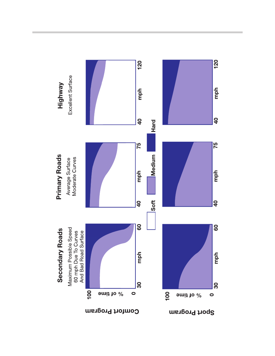
Comfort Program
When the comfort program is selected, the priority setting is for soft damping. Any changes
to dynamic movements detected by the sensor will allow the system to switch to either
medium or hard depending on how severe the dynamic changes are. The system will auto-
matically switch back to the soft setting when conditions warrant. This results in an ideal
combination of maximum comfort and optimum driving safety.
Sport Program
When the sport program is selected only the medium and hard damping settings are used.
The control unit selects the medium setting until dynamic changes require a higher damp-
ing force to maintain stability. The program characteristics allow the hard setting to be
selected sooner and held longer than the comfort program.
E
E3
38
8
E
E3
31
1//E
E3
32
2
8
Electronic Dampening Control
Vehicle Road Speed
The road speed comes
from the ABS/ASC or
DSC control module on
the E38.
The E31 signal comes
from the EKM and the
instrument cluster sup-
plies the signal for the E32.
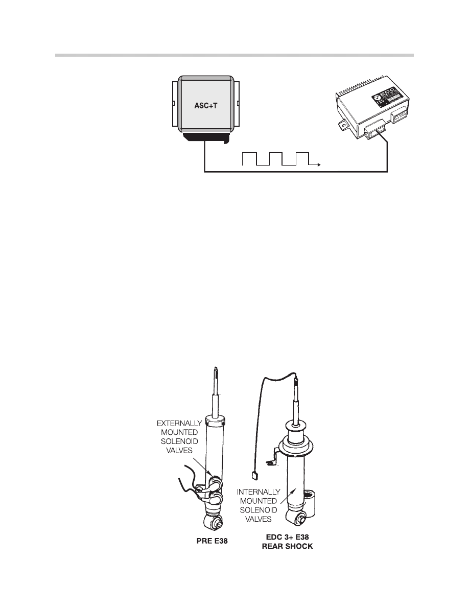
Solenoid Controlled Dampers E31/E32 and E38
The EDC system utilizes solenoid valves to change the valving in the damper to relieve the
oil flow through additional valves and create a softer damper value. The E38 solenoids are
mounted internally The E31/E32 use dampers with the solenoid valves mounted external-
ly of the dampers.
Front axle twin-tube, gas pressurized dampers and rear single tube dampers are used on
all EDC vehicles. Two solenoid valves are used for each strut assembly These valves pro-
vide an additional passage for the flow of oil in the soft and medium settings.
Both valves are never energized simultaneously. Damping can be varied front to rear, but
not side to side.
E38 wiring for control runs up through piston.
9
Electronic Dampening Control
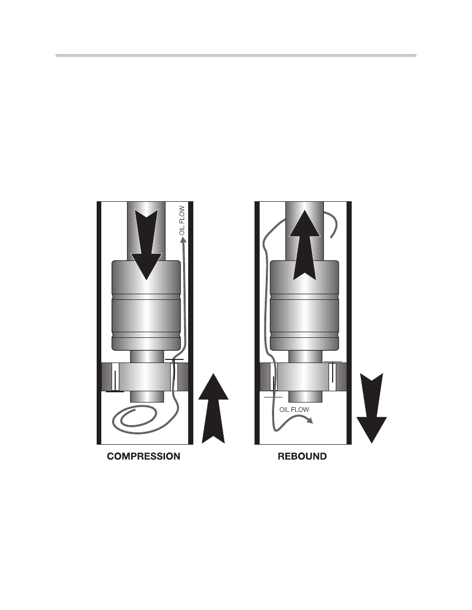
Basic Damper Operation
When the vehicle bounces the damper travels thru the compression and rebound stages.
The damper as illustrated corresponds to the EDC sport damper setting because the oil
basic dampers transfer uses only a mechanical one-way valve. The EDC III system can pro-
vide softer damping rates (soft, medium) by energizing solenoid valves which allow addi-
tional oil volume to transfer.
10
Electronic Dampening Control
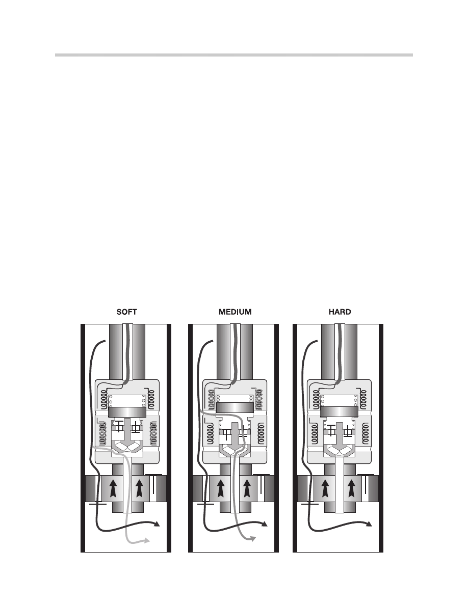
E38 Solenoid Controlled Damper Operation
There are three passages for oil transfer in the strut assembly. The first is the main oil trans-
fer valve. This valve is always open. The second and third valves are controlled by the EDC
solenoids. Through the two different orifices, the solenoids can vary the throughput of
hydraulic oil transfer thereby regulating the damping force.
S
So
offtt S
Se
ettttiin
ng
g -- In this setting the “soft solenoid in each shock is energized allowing oil trans-
fer through the mechanical orifice and larger diameter “soft” orifice. The soft setting pro-
vides oil transfer with the least restriction and the struts are set to the softest damping force.
M
Me
ed
diiu
um
m S
Se
ettttiin
ng
g - When the EDC control module’s processing calls for the medium setting,
the soft solenoid is de-energized and the “Medium” solenoid is energized so that the oil now
flows through the smaller valved orifice. This restricted oil flow increased the damping force
of the strut.
H
Ha
arrd
d S
Se
ettttiin
ng
g - When the EDC control module’s processing requires the hard setting, the
medium solenoid is switched “OFF”. This closes the solenoid controlled orifices and only
allows oil transfer through the main valve. The struts are now set to the maximum firmness.
This is also the failsafe setting of the EDC III system. With no power applied to the struts,
the system will be in the hard setting.
11
Electronic Dampening Control
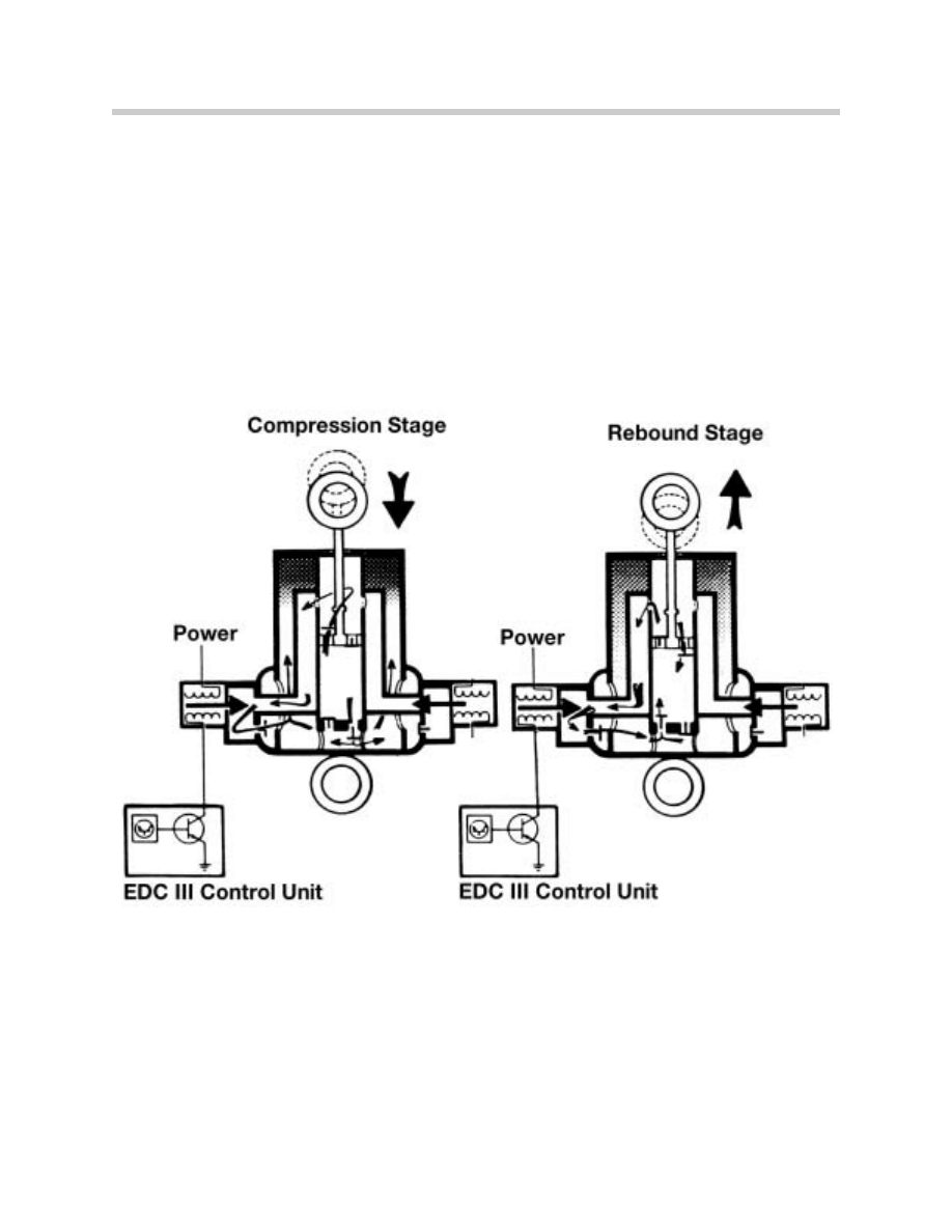
E31/E32 External Solenoid Damper Operation
The EDC III solenoid operation is identical for both soft and medium settings. The soft sole-
noid has a larger orifice so more oil can pass through the energized solenoid.
S
So
offtt S
Se
ettttiin
ng
g = Soft solenoid energized = Maximum oil transfer
M
Me
ed
diiu
um
m S
Se
ettttiin
ng
g = Medium solenoid energized = Moderate oil transfer
H
Ha
arrd
d S
Se
ettttiin
ng
g = No solenoids energized = No oil transfer through solenoids
12
Electronic Dampening Control
E38 I-P-O
13
Electronic Dampening Control
E31-E32 I-P-O
14
Electronic Dampening Control
Electronic Damper Control Functions
Automatic Load compensation
15
Electronic Dampening Control
EDC III R
Riid
de
e P
Prro
og
grra
am
m C
Co
om
mp
pa
arriis
so
on
n

16
Electronic Dampening Control
Safety Monitoring
All operating cycles and sensor inputs are checked by the control unit for plausibility and
function. Any faults that might occur are stored in the defect memory according to there
priority,
In the event of certain faults, the control module selects the "medium" damping setting.
• Steering angle sensor
e.g. bent wiper in sensor (signals do not match; max. deviation 30deg.) or tempo-
rary signal disturbed.
• Steering angle sensor
e.g. contact difficulties, wiper on conductor of potentiometer, loose contact in con-
ductor.
• Steering angle sensor
e.g. broken locating pin (sensor always supplies same signal), steering angle sen-
sor not fitted.
• Defective road speed signal
e.g. break in wire to EDC module.
• Defective acceleration sensor
e.g. signals not within working range.
If the soft solenoid fails, the medium setting is selected.
If the medium solenoid valve circuit or control module fails, the solenoids are de-ener-
gized which results in the hard or fail-safe setting.
17
Electronic Dampening Control
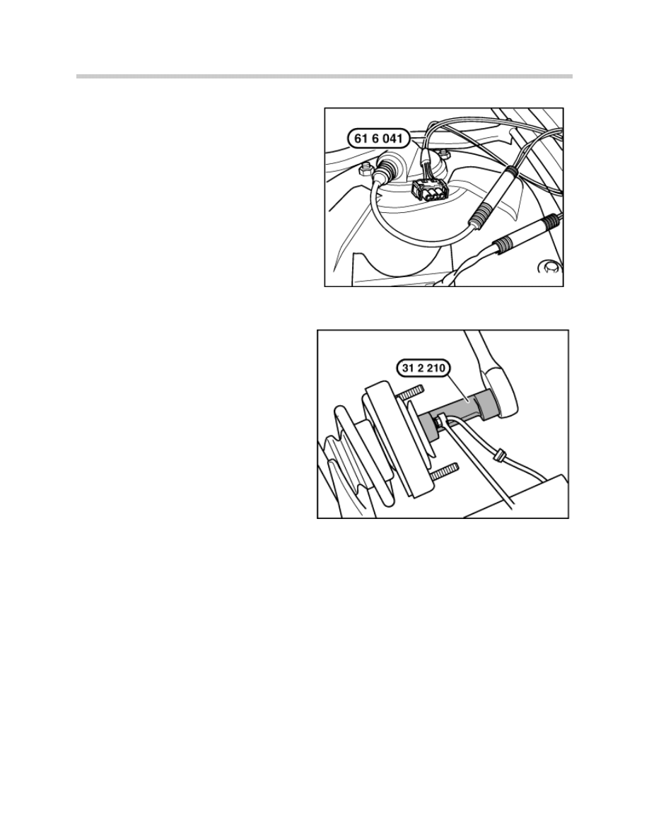
EDC Special Tools E38
A
Ad
da
ap
ptte
err H
Ha
arrn
ne
es
ss
s E
ED
DC
C S
Sh
ho
oc
ck
k S
So
olle
en
no
oiid
ds
s
P/N 90 88 6 616 041
Special adapter harness plugs into shock
harness for testing purposes.
S
Sh
ho
oc
ck
k A
As
ss
se
em
mb
blly
y R
Re
em
mo
ov
va
all S
So
oc
ck
ke
ett
P/N 90 88 6 312 210
Special socket for disassembly of shock
absorber with new solenoid harness.
Document Outline
- Main Menu
- Suspension Systems
- Braking Systems
- Fundamentals of ABS
- Introduction to DSC
- E46 DSC
- X5 DSC
- Level Control Systems
- EDC
- E65 EDC-K
- RDC / RDW
- Updates
Wyszukiwarka
Podobne podstrony:
W przebieg 20 03 07
org miedz wyklad 3 20 03 07
Pierwsi turyści od upadku Husajna (20 03 2009)
20 03 2012 Współczesne systemy polityczyne wykłady
19.20.02.2011r.i 20.03 i 16.04- prawo finansowe, Administracja WSEI Lublin, Makarzec
Prawo spółdzielcze, ART 18 PrSpółdz, V CSK 125/07 - wyrok z dnia 20 czerwca 2007 r
Historia kultury, Kultura historii- wyklad 20.03.2011, Kultura historii
Prawo cywilne - wykład 20.03.2012
makroekonomia 20.03, magisterskie, semestr 2, Makroekonomia
Szczęśliwa Siódemka Disco Polo (20 03 2010)
20 03 10 A
Prawo cywilne - prezentacja z dnia 20.03, Materiały - studia, I stopień, Prawo cywilne
Ćwiczenia z 20.03.2011 (niedziela) A. Szczepanek, UJK.Fizjoterapia, - Notatki - Rok I -, Biofizyka
MPLP 368;369 08.03.;20.03.2013
PODSTAWY ZARZĄDZANIA ćw 20.03.10 20, Materiały studia, Podstawy zarządzania ćwiczenia
20 03 2012 Współczesne doktryny militarne
Cennik TelefonĂłw w Ofercie Biznes od 20 03 2012
Fizyka wykład dajzeta 20 03 2011
20 03 2013 Kontrola i ocena
więcej podobnych podstron