TS-870: Installing the Inrad Roofing Filter Mod
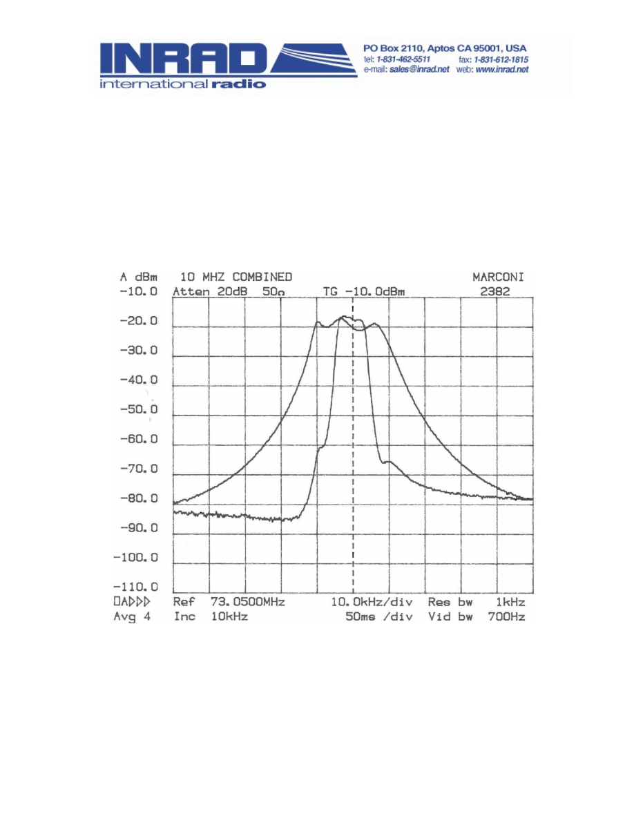
The TS-870 roofing filter mod consists of a 6 pole, 4 to 5 kHz wide filter
followed by a high dynamic range feedback amplifier. The amplifier provides
enough gain to overcome the filter insertion loss.
The plot below shows the sweep frequency response of the front end with the
Inrad roofing filter mod in place. For comparison, the OEM filter is about 15
kHz wide at the -6 dB points.
The result of the bandwidth improvement is the reduction of close in
intermodulation from multiple signals. The IMD dynamic range will be
improved up to 15 or more dB for signal spacings from 2 to 20 kHz. Also, the
blocking dynamic range will be improved for close in signals.
© 2009 International Radio Corporation. Modifications are done at your own risk; seek assistance if you
are not qualified to make these modifications. International Radio assumes no responsibility for any
damages or injuries resulting from improper installation of this modification kit.
Revised 2011-12-01
Frequently Asked Questions
1. What can you expect from this mod?
Less IMD in crowded band conditions, particularly from stations at offset
frequencies of 2 to 20 kHz on either side of the operating frequency.
2. Will it defeat the noise blanker?
There will be some change in the NB performance due to the narrower
bandwidth of the mod. In practice, it may not be noticeable.
3. Will this mod allow for wide band SSB, AM and FM reception?
The overall widest bandwidth will be determined by the roofing filter, which is
about 5 kHz. AM and FM will be degraded, but not excessively. Normal 2400
Hz SSB will not be affected.
Description of Operation
The roofing filter mod inserts a narrow band crystal filter after the first mixer
and before the OEM roofing filter. An amplifier is included to compensate for
the filter loss. Reducing the bandwidth at this point in the radio helps to keep
strong off-frequency signals out of the second mixer, where they can cause
intermodulation. Transmission is not changed, as it does not pass through
the roofing filter.
Installation Instructions
© 2011 International Radio Corporation
- 2 -
Warning: Modern radios contain components which may be damaged by
static discharge. Precautions must be taken to eliminate any static
electricity buildup between the operator and the radio before any of the
internal circuits are touched. If you are not familiar with the proper
techniques for this, consult the Radio Amateurs Handbook.
Warning: This modification requires a high level of soldering skill, possibly
beyond that normally possessed by the average radio amateur.
Professional assistance is advised if you are not confident that you have
this ability.
Note: If you have a known test signal available before you start, note the S
meter reading for the main and sub receivers. After the installation, the S
meter should read about the same as before.

Preparing the Inrad Mod for Installation
1.
Prepare one side of each coax cable by stripping 1/4 inch of outer
covering and shield from the end. Strip approximately 1/8 inch of
insulation from the center conductor.
2.
Next, prepare the opposite side of each coax cable to accept a TMP
connector by stripping ½ inch of outer covering and shield. Strip
approximately 1/4 inch of insulation from the center conductor. Insert the
center conductor into the TMP connector center pin and solder it in. Then
take the dressed braid and solder it to the connector outer shield. The
cables should now be ready for the installation. See Figure 1 for more
information on the cable preparation.
3.
Set prepared cables aside.
Preparing the Radio for Installation
If you haven't already read the instructions completely, please do so now
before continuing.
1.
Remove the DC power cord from the transceiver.
2.
Place the radio upside down on a soft surface such as a towel, with the
front panel facing you.
3.
Remove the screws holding the bottom cover in place. Remove the
bottom cover.
4.
Remove the metal shield from the rear of the RF board on the left side.
5.
Locate L65 and L67 on the left side of the RF board. This is the area for
the mod once we turn the board over.
6.
Starting at the rear of the RF board, remove the coax cable coded yellow
from CN2.
7.
Remove the plain coax cable from CN4.
8. Remove the small ribbon cable on the right side of the board from CN13.
9. Remove the 7 board mounting screws fro the RF board.
10.
Lift the RF board up and bend it over the front panel. Use a soft cloth or
towel to cushion the board as it lies on the front panel.
© 2011 International Radio Corporation
- 3 -

11.
Locate the work area between L65 and L67 on the trace side of the board.
Compare it to Figure 2. Carefully remove C179. See Figure 2.
12.
Examine Figure 3. The hot wire of the coax cable going to J1 on the mod
is connected to the terminal of L65 which went to C179. The pin on L65 is
a good place to solder it. The shield is connected to the nearby ground
pad.
13.
Examine Figure 3 again. The hot wire of the coax cable going to J2 on the
mod is connected to the terminal of L67 which went to C179. The pin on
L67 is a good place to solder it. The shield is connected to the nearby
ground pad.
14.
Check that the soldering is secure before turning the board over.
Dress
the wires to exit in the space between the RF and IF boards.
15.
Solder the white wire to the center pin in a group of 3 on L65 as shown in
Figure 3.
16.
Reverse the removal procedure to reinstall the PC board.
17.
Solder the other end of the white wire to the +12V pad on the mod board.
Ground will return through the coax shields.
18.
Replace the shield.
19.
Figure 4 shows the installation of the mod assembly. The two stick down
board mounts should be inserted as indicated in the figure. It will be
easier to position the mod board if the ribbon cable and other wires are
temporarily held out of the way.
20.
Insert the standoffs into the two holes in the mod board.
21.
Position the mod board with J1 on the left side. Plug in the two coax
cables. The one from L65 goes in J1 and the one from L67 goes in J2.
22.
Replace the ribbon cable and the other wires
23.
Check your work. Replace the bottom cover of the radio.
© 2011 International Radio Corporation
- 4 -
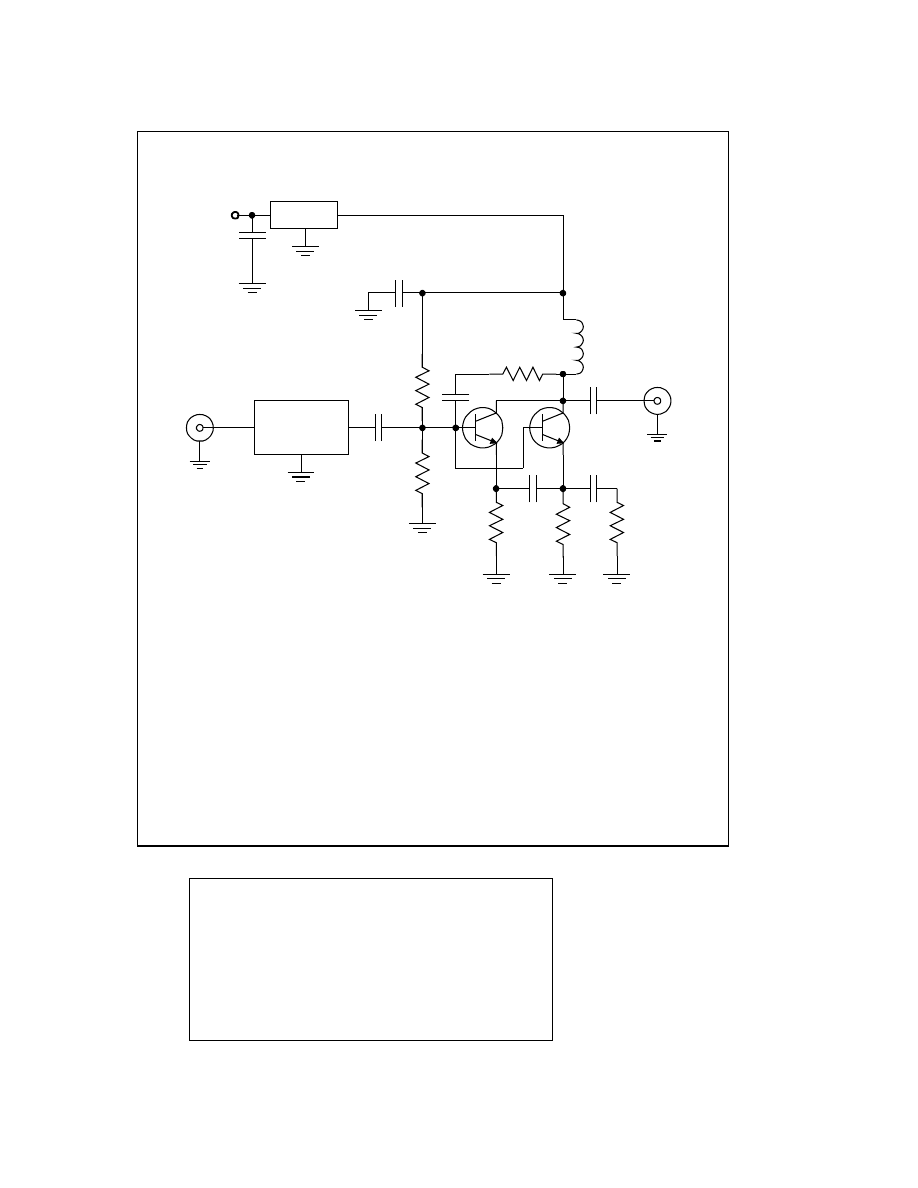
C1,2,3,4,5,6
0.1uF
C7
0.47uF
L1
2.2uH
R1
3.9K
R2
2.2K
R3,4
68
R5
12
R6
220
Q1,2
MPS5179
73.05 MHz
Xtal Filter
J1
C1
C2
C3
C4
C5
C6
J2
FL1
L1
R1
R2
R3
R4
R5
R6
Q1
Q2
78L05
C7
+12V
TS 870 Roofing Filter Mod W2VJN 9/14/2009
© 2011 International Radio Corporation
- 5 -
Parts List
•
Assembled Inrad 117 board
•
2 RG-178 coax cables, 9” each
•
2 male TMP connectors
•
White wire 9”, #24
•
2 board mounts, Mouser 561-LAD187
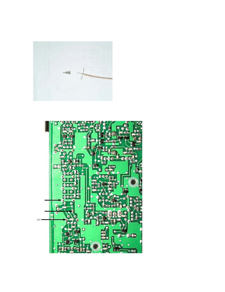
Figure 1. Preparation of coax cable.
Figure 2. Area for modification. Bottom of pc board.
© 2011 International Radio Corporation
- 6 -
L67
C179
L65

Figure 3. View of the board modification.
Figure 4. Completed mod.
© 2011 International Radio Corporation
- 7 -
Document Outline
Wyszukiwarka
Podobne podstrony:
roofing filter w hf1000
Icom 756pro3 filter roofing mod
Mała chirurgia II Sem IV MOD
W11 mod
sem mod imp(1)
W12 mod
mod części 15 07
P20 HH Mod
interna mod 1
Mod ryz lacz
Efficient VLSI architectures for the biorthogonal wavelet transform by filter bank and lifting sc
10 2009 Twierdzenia mod n
Spr mod 2
lecture 15 Multivariate and mod Nieznany
Applications of polyphase filters for bandpass sigma delta analog to digital conversion
mod 2007 8 FM
bb1 ep mod 9
Fine Filters CJC
interna mod 2
więcej podobnych podstron