Service Source
K
Macintosh Classic/
Classic II/Performa 200
Service Source
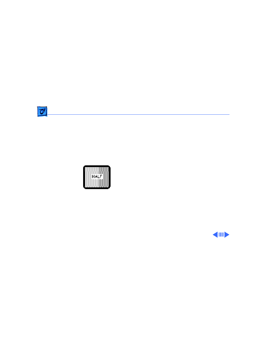
K
Basics
Macintosh Classic/Classic II/
Performa 200
Basics
Overview - 1
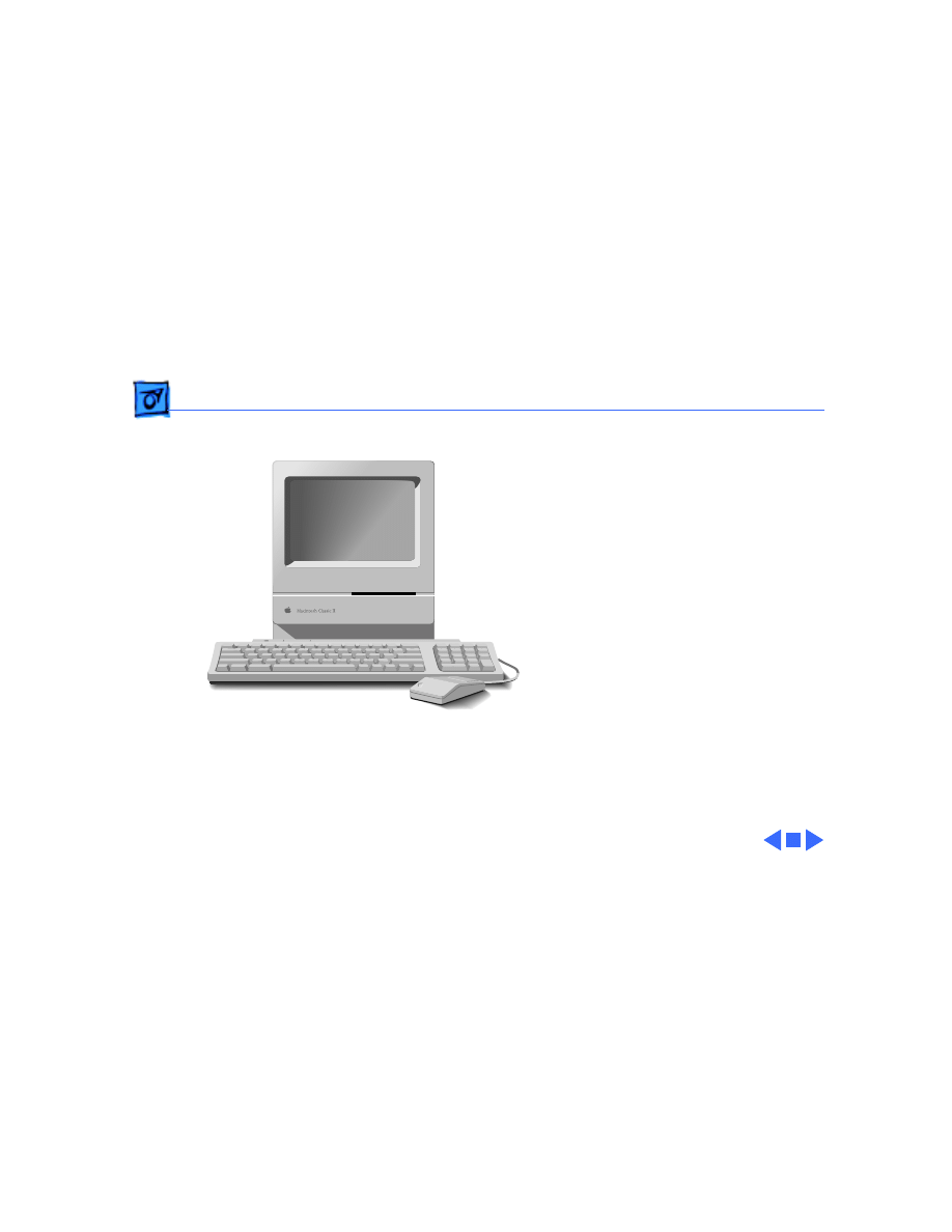
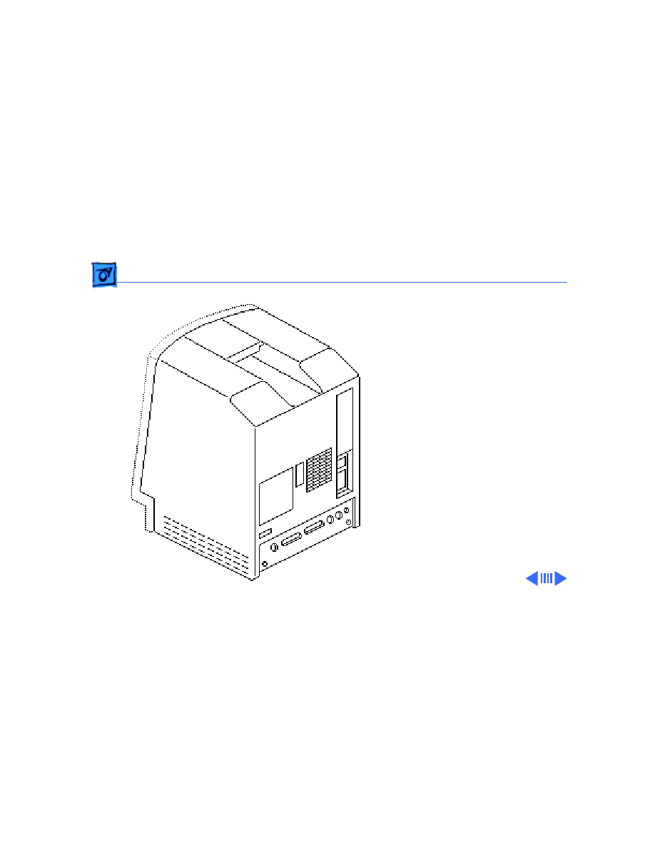
Overview
This manual includes
complete repair procedures
for the Macintosh Classic,
Classic II, and Performa
200.
Figure: Macintosh Classic/Classic II and Performa 200
Service Source
K
Specifications
Macintosh Classic/Classic II/
Performa 200

Specifications
Processor - 1
Processor
Classic CPU
Motorola 68000 microprocessor
7.8336 MHz
32-bit internal data bus
256-byte instruction and data caches
Classic II/Per 200
CPU
Motorola 68030 microprocessor
16 MHz
32-bit internal data bus
256-byte instruction and data caches

Specifications
Memory - 2
Memory
RAM
Classic:
1 MB, expandable to 4 MB (120 ns or faster SIMMs)
Classic II/Per 200:
2 MB, expandable to 10 MB (120 ns or faster SIMMs)
ROM
512K
PRAM
256 bytes of parameter memory
Cache Connector
44-pin connector for optional memory expansion
256K by 4-bit DRAMs
Includes two SIMM connectors for additional RAM expansion

Specifications
Disk Storage - 3
Disk Storage
Floppy Drive
Internal 1.4 MB floppy drive
Optional external 800K or 1.4 MB floppy drive
Hard Drive
Classic:
Optional internal 40 MB hard drive; optional external SCSI drive
Classic II/Per 200:
Internal 40 MB or 80 MB hard drive; optional external SCSI
drive

Specifications
I/O Interfaces - 4
I/O Interfaces
Floppy Drive
External drive port; DB-19 connector
SCSI
One SCSI parallel port; DB-25 connector
Apple Desktop Bus
One Apple Desktop Bus (ADB) port; mini DIN-4 connector
Serial
Two RS-422 serial ports; mini DIN-8 connectors
Sound
Dual-channel headphone connector
Connected to the monophonic sound output
Macintosh Classic does not provide true two-channel output
(although stereo jack may be used)

Specifications
I/O Devices - 5
I/O Devices
Keyboard
80 keys, with numeric keypad; ADB connector
Mouse
Mechanical tracking; ADB connector
Classic II/Per 200
Microphone
Electret, omnidirectional; output voltage is 4 mV, peak to peak, at
normal volume

Specifications
Sound and Video - 6
Sound and Video
Sound Generator
Classic:
Four-voice sound with 8-bit digital/analog conversion, using
22-kHz sampling rate
Video Display
Classic II/Per 200:
Monophonic, 8-bit digital/analog conversion using 22-kHz
sampling rate; capable of driving stereo headphones or other
stereo equipment through the sound jack
9-in. (diagonal) screen; high-resolution, 512 by 342 pixel,
bit-mapped, monochrome display

Specifications
Electrical - 7
Electrical
Line Voltage
100–120 V AC
Frequency
47–63 Hz, single phase
Maximum Power
100 W

Specifications
Physical - 8
Physical
Dimensions
Height: 13.2 in. (33.6 cm)
Width: 9.7 in. (24.6 cm)
Depth: 11.2 in. (28.5 cm)
Weight
16–17.1 lb. (7.3-7.8 kg) not including internal hard drive

Service Source
K
Troubleshooting
Macintosh Classic/Classic II/
Performa 200

Troubleshooting
General/ - 1
General
The Symptom Charts included in this chapter will help you
diagnose specific symptoms related to your product. Because cures
are listed on the charts in the order of most likely solution, try
the first cure first. Verify whether or not the product continues to
exhibit the symptom. If the symptom persists, try the next cure.
(Note: If you have replaced a module, reinstall the original module
before you proceed to the next cure.)
If you are not sure what the problem is, or if the Symptom Charts
do not resolve the problem, refer to the Flowchart for the product
family.
For additional assistance, contact Apple Technical Support.

Troubleshooting
Symptom Charts/Video - 2
Symptom Charts
Video
Screen is dark; audio
and drive operate
1 Readjust brightness (see Adjustments).
2 Readjust contrast (see Adjustments).
3 Check yoke cable connection.
4 Replace power/sweep board.
5 Replace logic board. Retain customer’s SIMMs.
6 Replace CRT.
Screen is bright and
audio is present, but
no video information
is visible
1 Replace power/sweep board.
2 Replace logic board. Retain customer’s SIMMs.

Troubleshooting
Symptom Charts/Video
(Continued)
- 3
Video
(Continued)
Screen is dark; fan is
not running
Replace power/sweep board.
Single vertical line is
displayed
1 Replace power/sweep board.
2 Replace logic board. Retain customer’s SIMMs.
3 Replace CRT.
Single horizontal line
is displayed
1 Replace power/sweep board.
2 Replace logic board. Retain customer’s SIMMs.
3 Replace CRT.
Vertical bars or
stripes are displayed
1 Replace power/sweep board.
2 Replace logic board. Retain customer’s SIMMs.

Troubleshooting
Symptom Charts/Video
(Continued)
- 4
Video
(Continued)
Horizontal bars or
stripes are displayed
1 Replace power/sweep board.
2 Replace logic board. Retain customer’s SIMMs.
White dot is displayed
in center of screen
1 Verify that yoke cable is connected.
2 Replace power/sweep board.
3 Replace CRT.
Screen jitters
1 Move computer away from adjacent monitors or other
electrical equipment that may cause interference.
2 Replace power/sweep board.

Troubleshooting
Symptom Charts/Video
(Continued)
- 5
Video
(Continued)
After replacement of
failed hard drive,
video distortion
appears in upper and
lower corners of
screen
Check whether hard drive replacement was like-for-like. If not,
install a like drive.

Troubleshooting
Symptom Charts/Floppy Drives - 6
Floppy Drives
Audio and video are
present, but internal
floppy drive does not
operate
1 Replace bad disk with known-good disk.
2 Replace floppy drive cable.
3 Replace floppy drive.
4 Replace logic board. Retain customer’s SIMMs.
External floppy drive
does not operate
1 Replace bad disk with known-good disk.
2 Be sure external floppy drive is placed on right side of
computer.
3 Replace external floppy drive.
4 Replace logic board. Retain customer’s SIMMs.
Disk ejects; display
shows icon with
blinking “X”
1 Replace bad disk with known-good system disk.
2 Replace floppy drive.
3 Replace logic board. Retain customer’s SIMMs.

Troubleshooting
Symptom Charts/Floppy Drives
(Continued)
- 7
Floppy Drives
(Continued)
Unable to insert disk
all the way
1 Insert opened paper clip into hole beside floppy drive.
2 Switch off system and hold mouse button down while
switching system on (to complete eject cycle).
3 Replace floppy drive.
Does not eject disk
1 Insert opened paper clip into hole beside floppy drive.
2 Switch off system and hold mouse button down while
switching system on (to complete eject cycle).
3 Replace floppy drive.
Internal floppy drive
runs continuously
1 Replace bad disk with known-good disk.
2 Replace floppy drive.
3 Replace logic board. Retain customer’s SIMMs.
4 Replace floppy drive cable.

Troubleshooting
Symptom Charts/Hard Drives - 8
Hard Drives
Internal or external
hard drive does not
operate
1 Verify that SCSI loopback card is not attached.
2 Check that internal SCSI terminator is positioned in
connector properly.
3 Verify that internal hard drive has all three terminating
resistor packs on circuit board.
4 Replace hard drive data cable.
5 Replace hard drive.
6 Replace logic board. Retain customer’s SIMMs.
Works with internal
or external SCSI
device but does not
work with both.
1 Verify that SCSI device ID switch setting on external device
is higher than 0. Also verify that ID switch setting on
external SCSI device does not duplicate ID switch settings on
any other attached external SCSI devices.
2 Replace terminator on external SCSI device.
3 Verify that terminator is installed on internal SCSI drive.
4 Replace SCSI select cable.

Troubleshooting
Symptom Charts/Peripheral - 9
Peripheral
Cursor does not move
1 Check mouse connection.
2 If mouse was connected to keyboard, connect it to rear ADB
port instead. If mouse works, replace keyboard.
3 If mouse does not work in any ADB port, replace mouse.
4 Replace logic board. Retain customer’s SIMMs.
Cursor moves, but
clicking the mouse
button has no effect
1 Replace mouse.
2 Replace logic board. Retain customer’s SIMMs.

Troubleshooting
Symptom Charts/Peripheral
(Continued)
- 10
Peripheral
(Continued)
Cannot double-click
to open application,
disk, or server
1 Remove extra system files on hard drive.
2 Clear parameter RAM. Hold down <Shift> <Option>
<Command> keys and select Control Panel from Apple pull-
down menu. Reset mouse controls.
3 If mouse was connected to keyboard, connect it to rear ADB
port instead. If mouse works, replace keyboard.
4 If mouse does not work in any ADB port, replace mouse.
5 Replace logic board. Retain customer’s SIMMs.
No response to any
key on keyboard
1 Check keyboard connection to ADB port.
2 Replace keyboard cable.
3 Replace keyboard.
4 Replace logic board. Retain customer’s SIMMs.

Troubleshooting
Symptom Charts/Peripheral
(Continued)
- 11
Peripheral
(Continued)
Known-good
ImageWriter or
ImageWriter II does
not print
1 Make sure that Chooser and Control Panel are set correctly.
2 Replace printer driver and system software with known-
good.
3 Replace printer interface cable.
4 Replace logic board. Retain customer’s SIMMs.
Known-good
LaserWriter does not
print.
1 Make sure that Chooser and Control Panel are set correctly.
2 Replace printer driver and system software with known-
good.
3 Refer to Networks manual.

Troubleshooting
Symptom Charts/Miscellaneous - 12
Miscellaneous
Clicking, chirping,
or thumping sound
1 Verify that logic board power cable is connected at J12 on
logic board.
2 Replace power/sweep board.
3 Replace logic board. Retain customer’s SIMMs.
Smoke/odor
Replace power/sweep board.
No video, no audio, and
no drive operation
1 Connect power cord.
2 Switch power on.
3 Replace power cord.
4 Replace fuse.
5 Replace power/sweep board.
6 Replace logic board. Retain customer’s SIMMs.

Troubleshooting
Symptom Charts/Miscellaneous
(Continued)
- 13
Miscellaneous
(Continued)
“Sad Macintosh” icon
1 Replace bad disk with known-good disk.
2 Verify that jumper on memory expansion board is configured
correctly for “SIMMs” or “No SIMMs.” (See “Memory
Upgrade” in Additional Procedures.)
3 On 4 MB Macintosh Classic, confirm SIMMs used are eight-
chip SIMMs. (See Memory manual.) Any 1 MB SIMMs with
fewer than eight chips won’t work in the Macintosh Classic.
4 On Macintosh Classic, replace optional memory expansion
board; on Macintosh Classic II/Performa 200, replace
optional SIMMs in two SIMMs slots on logic board.
5 Replace logic board. Retain customer’s SIMMs.

Troubleshooting
Symptom Charts/Miscellaneous
(Continued)
- 14
Miscellaneous
(Continued)
Screen shows “Sad
Macintosh” icon and
black vertical lines;
screeching sound
1 Verify that jumper on memory expansion board is configured
correctly for “SIMMs” or “No SIMMs.” (See “Memory
Upgrade” in Upgrades.)
2 On 4 MB Macintosh Classic, confirm SIMMs used are eight-
chip SIMMs. (See Memory manual.) Any 1 MB SIMMs with
fewer than eight chips won’t work in the Macintosh Classic.
3 On Macintosh Classic, replace optional memory expansion
board; on Macintosh Classic II/Performa 200, replace
optional SIMMs in two SIMMs slots on logic board.
4 Replace logic board. Retain customer’s SIMMs.

Troubleshooting
Symptom Charts/Miscellaneous
(Continued)
- 15
Miscellaneous
(Continued)
No power
1 Connect power cord.
2 Switch power on.
3 Replace power cord.
4 Replace fuse.
5 Replace power/sweep board.
6 Replace logic board. Retain customer’s SIMMs.

Service Source
K
Take Apart
Macintosh Classic/Classic II/
Performa 200
Take Apart
Cover - 1
Cover
No preliminary steps are
required before you begin
this procedure.
±
Warning:
This product
contains high voltage and a
high-vacuum picture tube.
To prevent serious personal
injury or equipment
damage, review CRT safety
and discharge instructions
in Bulletins/Safety.
Take Apart
Cover - 2
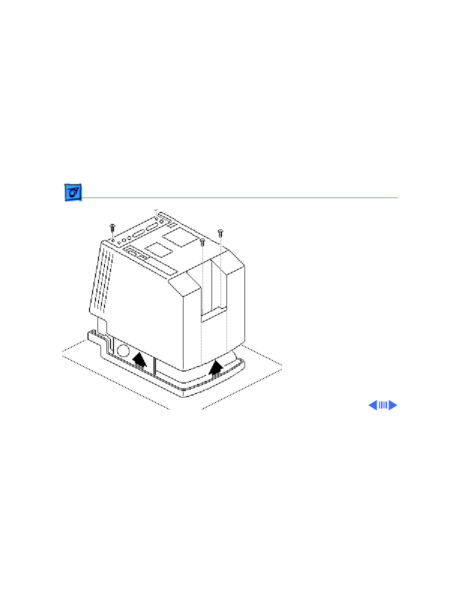
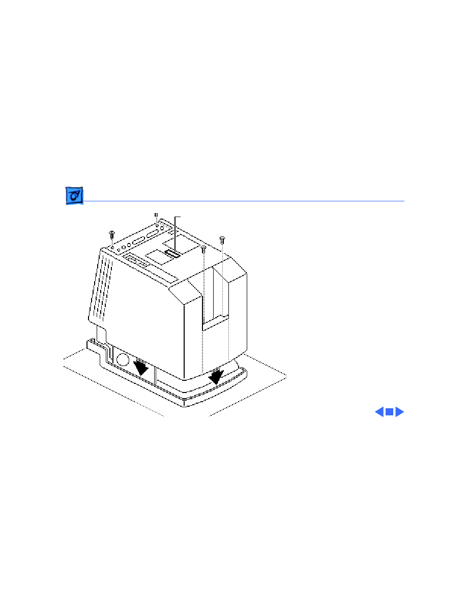
1 Using a Torx
screwdriver, remove
the four case screws.
Using a case spreader or
pull-apart tool,
separate the cover from
the chassis.
2 Carefully lift the cover
and set it aside.
±
Warning:
The edges of
the metal chassis may be
sharp. When moving the
computer with the cover off,
be sure to handle the chassis
carefully.

Take Apart
Cover - 3
Note:
When replacing the
cover, be sure to install the
two black case screws in the
bottom of the cover and the
two silver-colored case
screws in the top of the
cover.
Take Apart
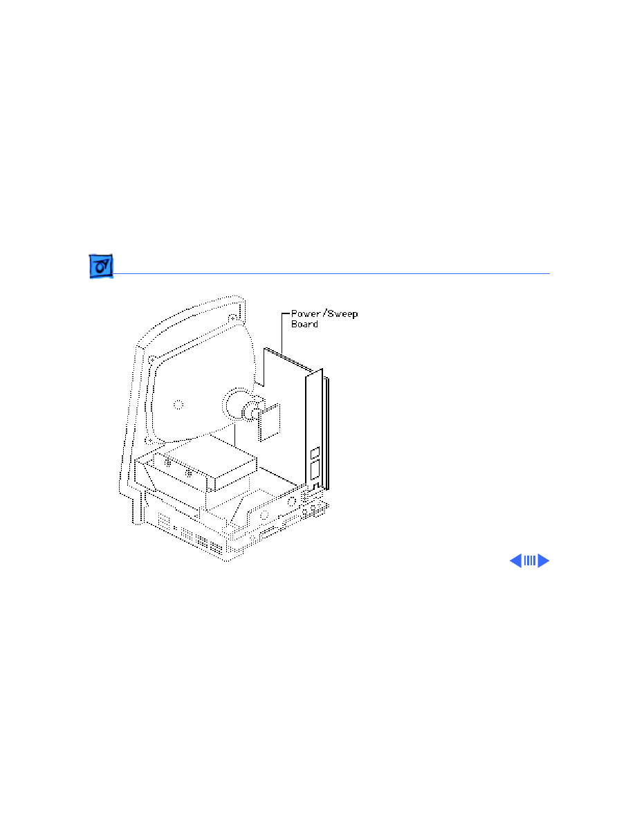
Power/Sweep Board - 4
Power/Sweep
Board
Before you begin:
• Remove the cover
• Discharge the CRT
• Remove the anode cap
±
Warning:
This product
contains high voltage and a
high-vacuum picture tube.
To prevent serious personal
injury or equipment
damage, review CRT safety
and discharge instructions
in Bulletins/Safety.
Caution:
To prevent ESD

Take Apart
Power/Sweep Board - 5
damage to components, wear
a grounding wriststrap.
Never use a grounding
wriststrap until after
discharging the CRT.

Take Apart
Power/Sweep Board - 6
1 Using a Torx
screwdriver, remove
the screw that secures
the ground wire to the
upper corner of the CRT.
2 Carefully pull off the
video board from the
neck of the CRT.
Note:
If sealant holds
the board in place, cut
the sealant with an art
knife.
Take Apart
Power/Sweep Board - 7
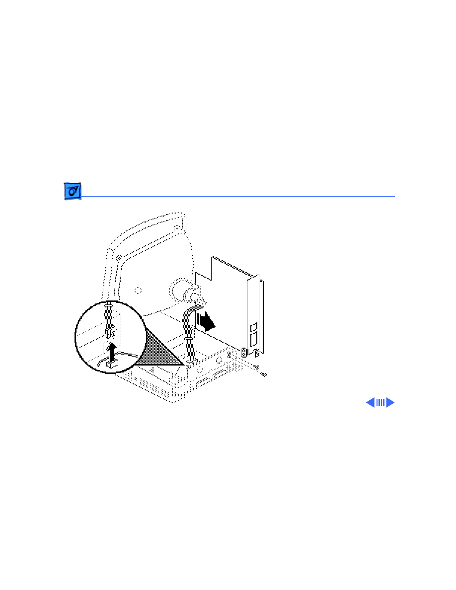
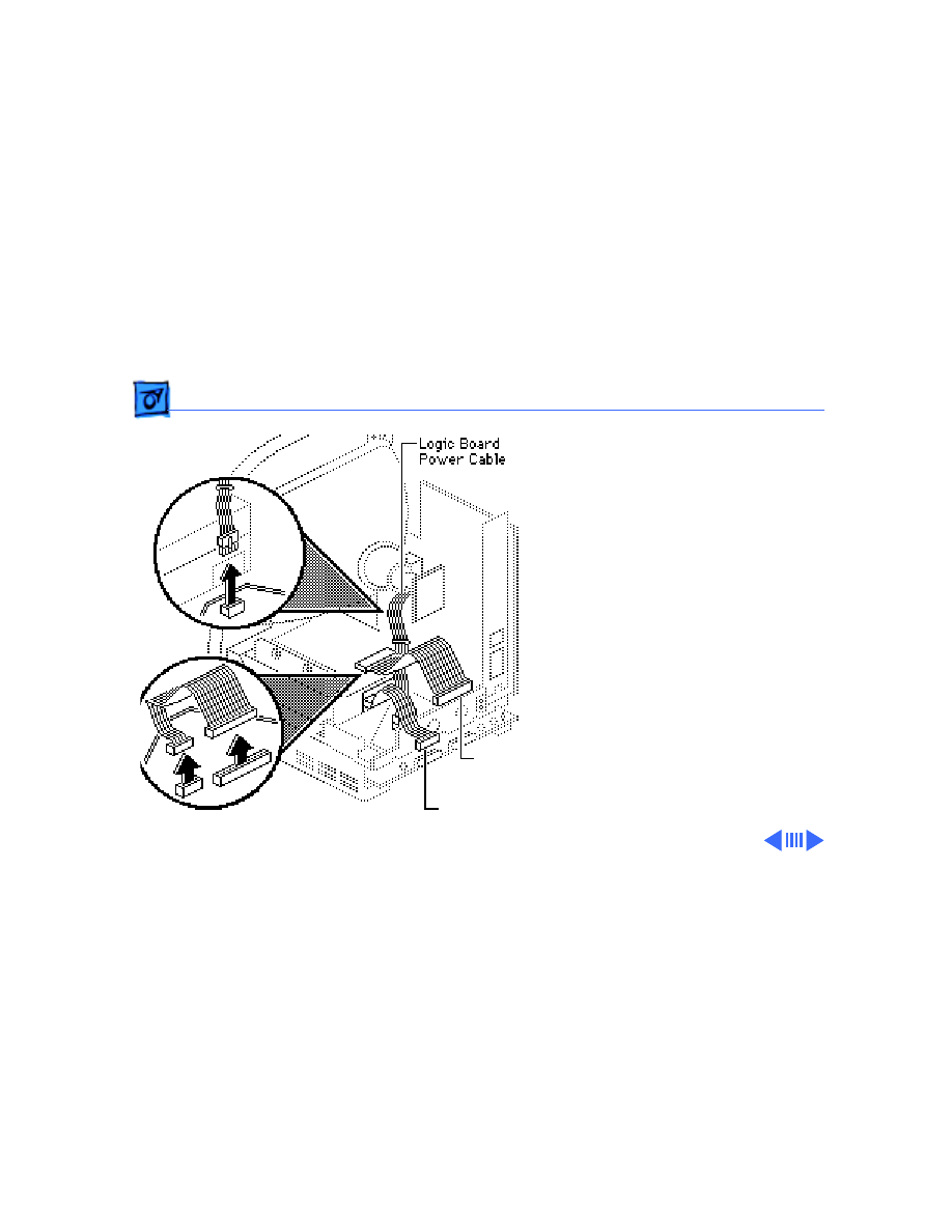
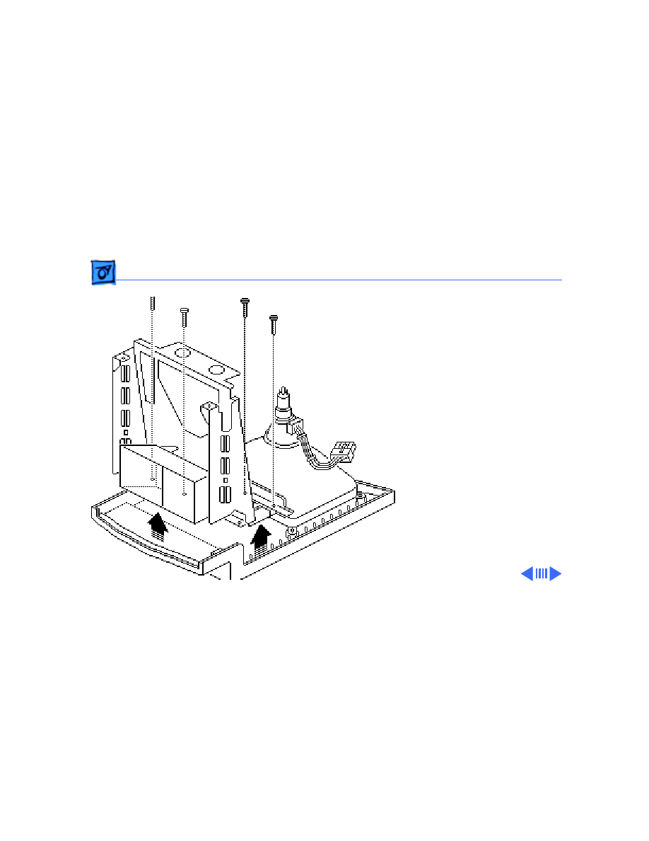
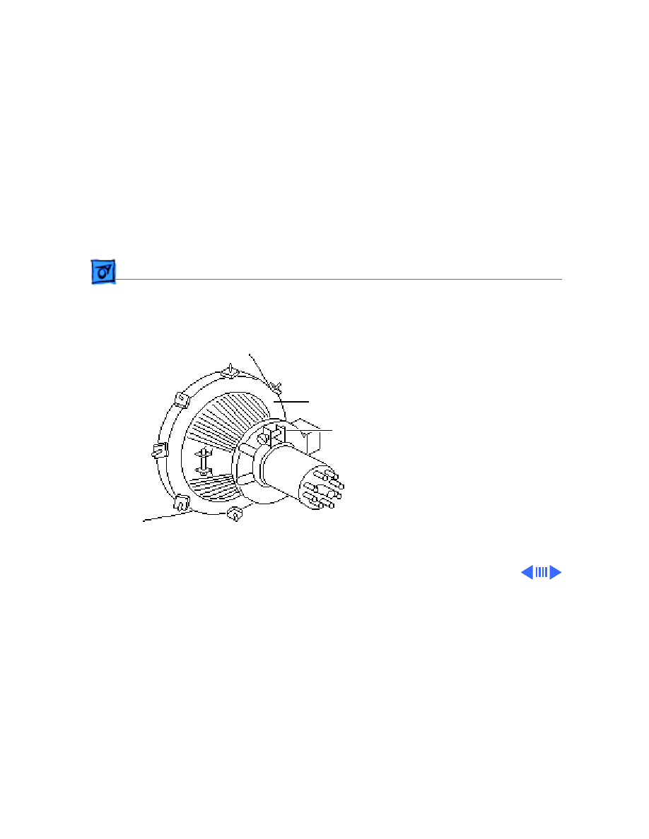
3 Remove the logic board
power cable from the
logic board. Remove the
Phillips screws that
secure the power/sweep
bracket to the chassis
and pull the board
slightly away from the
chassis.
Note:
Most power/sweep
brackets are secured by
two screws; however,
some are secured by
three.
Take Apart
Power/Sweep Board - 8
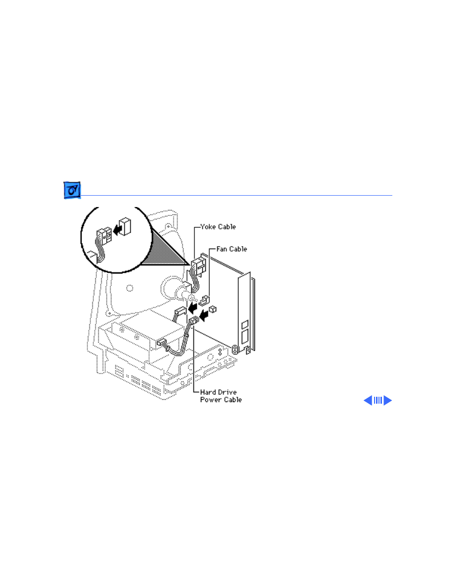
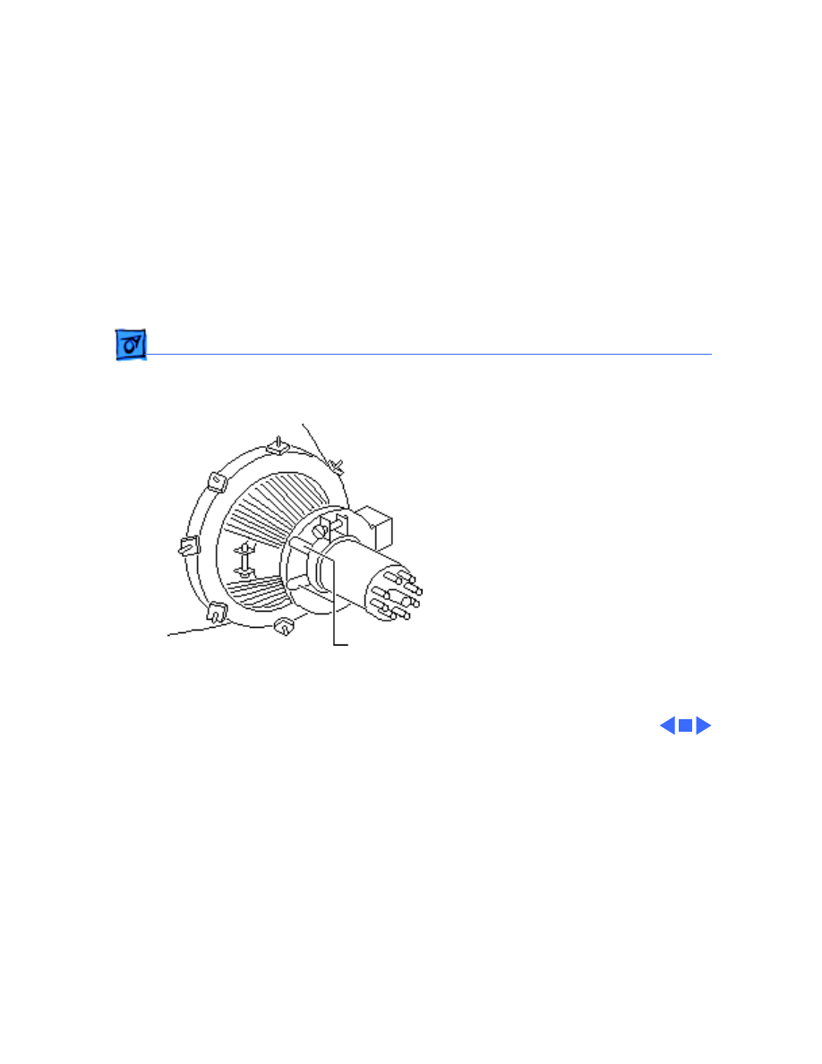
5 Remove the following
cable connectors from
the power/sweep board:
• Yoke cable
• Fan cable
• Hard drive power
cable (if present)
Take Apart
Power/Sweep Board - 9
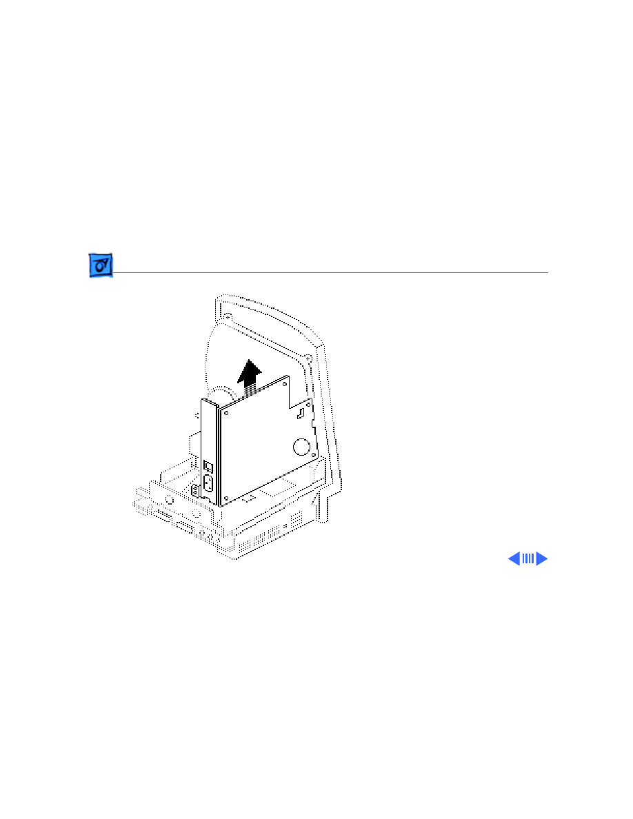
6 Lift the board free.
Take Apart
Power/Sweep Board - 10
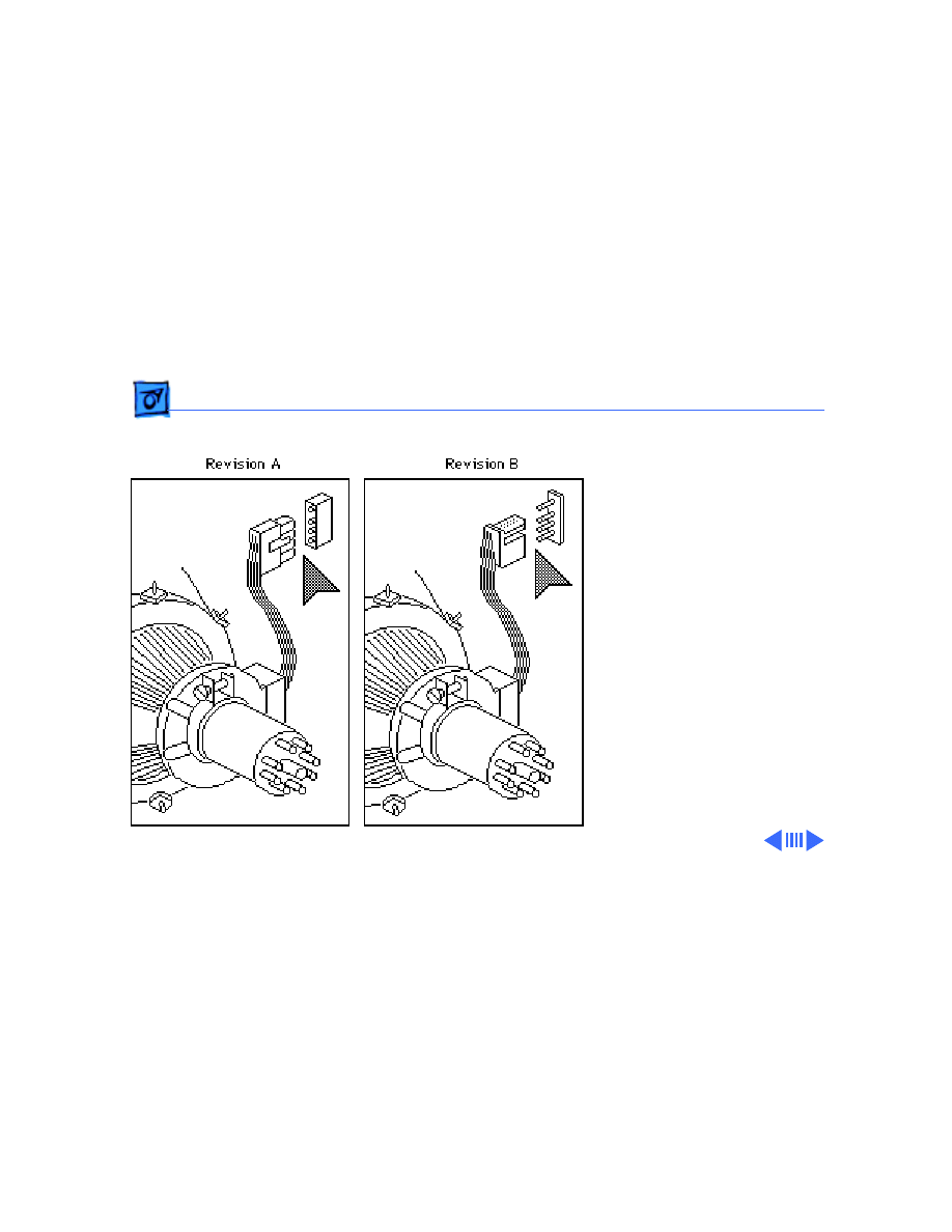
Note:
The two versions of
the power/sweep board,
Rev A and Rev B, are
functionally equivalent, but
they are not
interchangeable.
In addition, a Rev A power/
sweep board must be used
with a Rev A CRT yoke
assembly and a Rev A or Rev
B cover. A Rev B power/
sweep board must be used
with a Rev B CRT yoke
assembly and a Rev B cover.

Take Apart
Power/Sweep Board - 11
To identify compatible
versions of the power/sweep
board, CRT assembly, and
cover, examine the CRT yoke
connector. Power/sweep
board Rev A has plastic
sleeves surrounding the
prongs; the prongs are
exposed on power/sweep
board Rev B.
Take Apart
Logic Board - 12
Logic Board
Before you begin:
• Remove the cover
• Discharge the CRT
• Remove the memory
expansion board
±
Warning:
This product
contains high voltage and a
high-vacuum picture tube.
To prevent serious personal
injury or equipment
damage, review CRT safety
and discharge instructions
in Bulletins/Safety.

Take Apart
Logic Board - 13
Caution:
To prevent ESD
damage to components, wear
a grounding wriststrap.
Never use a grounding
wriststrap until after
discharging the CRT.
Take Apart
Logic Board - 14
1 Remove the following
cable connectors from
the logic board:
• Logic board power
cable
• Floppy drive cable
• Hard drive data
cable (if present)
Hard Drive
Floppy Drive Cable
Data Cable
Take Apart
Logic Board - 15
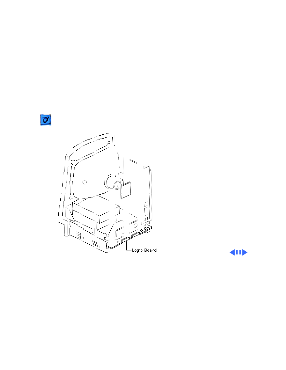
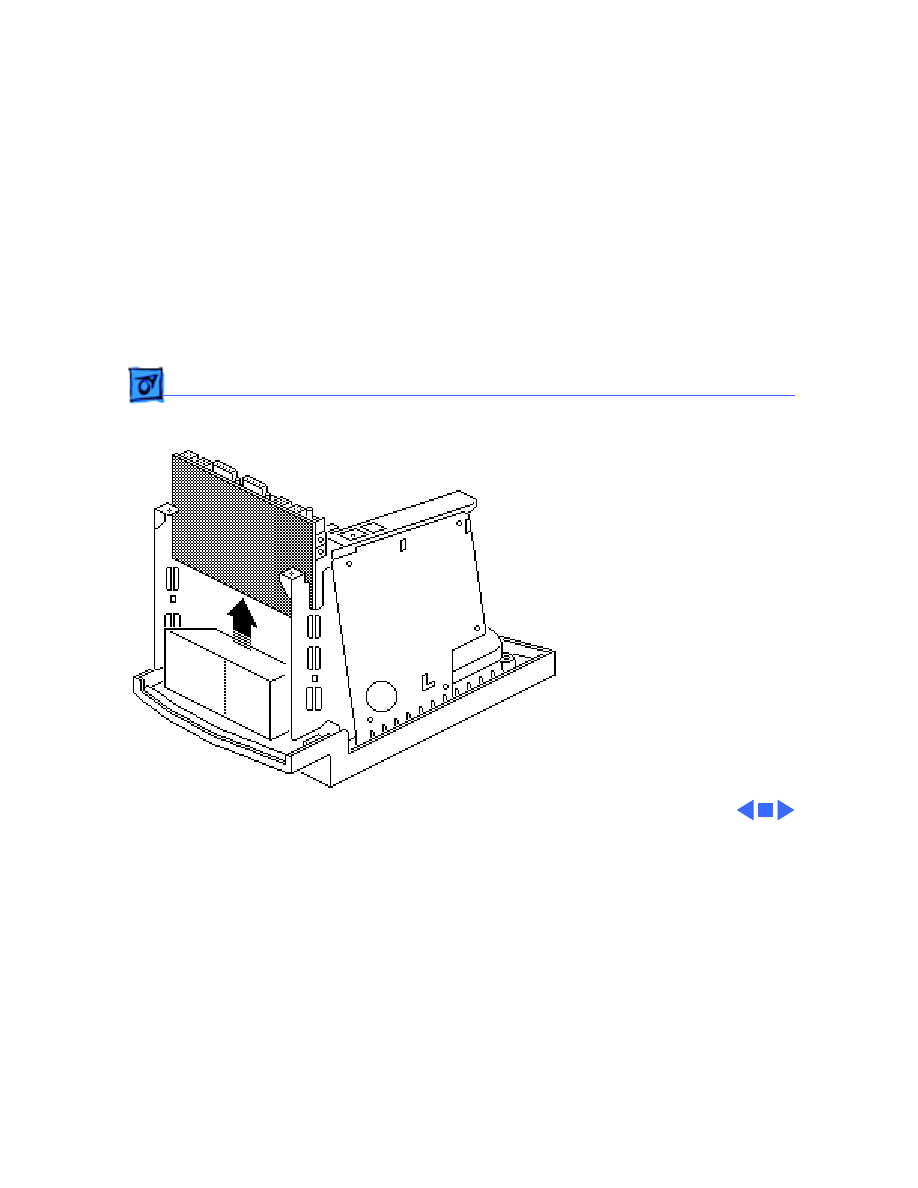
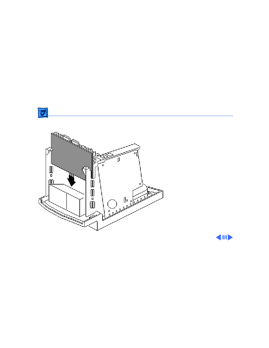
2 Grasp the logic board by
the corners and slide it
straight up and out of the
chassis.
Replacement Note:
Remove
the SIMMs from the
defective logic board and
install them in the
replacement logic board.
(See Memory manual.)
Take Apart
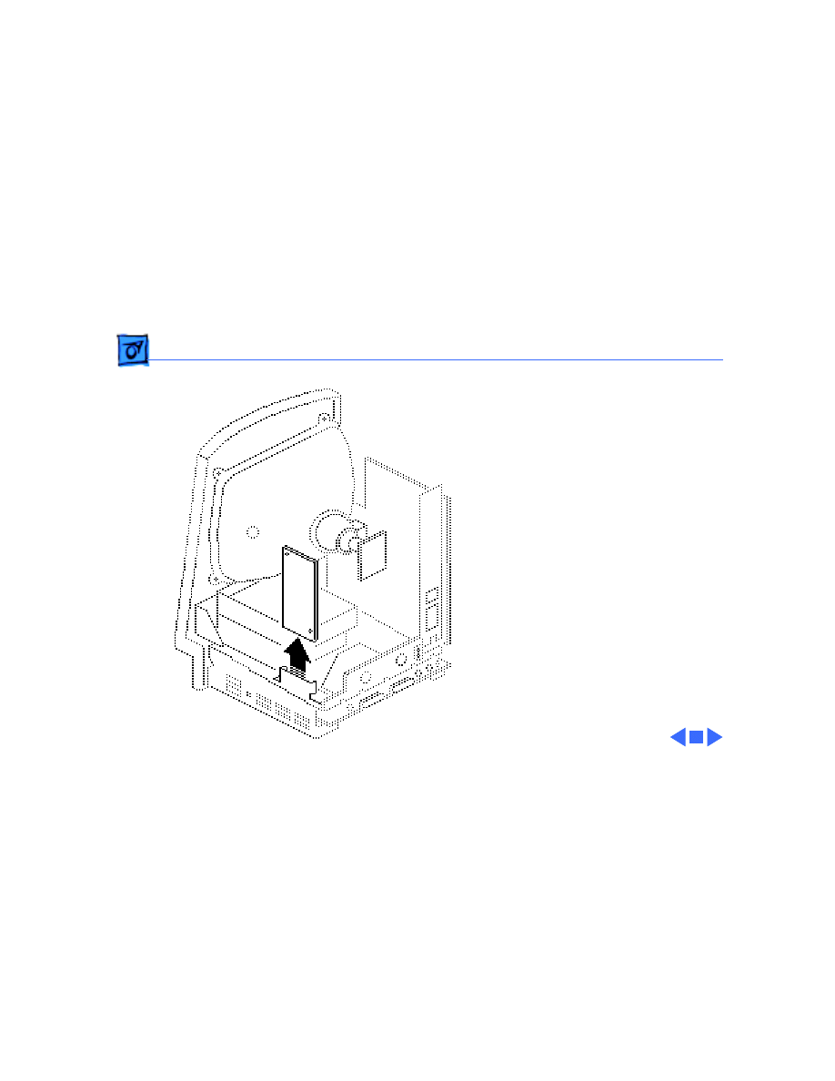
Hard Drive - 16
Hard Drive
Before you begin:
• Remove the cover
• Discharge the CRT
±
Warning:
This product
contains high voltage and a
high-vacuum picture tube.
To prevent serious personal
injury or equipment
damage, review CRT safety
and discharge instructions
in Bulletins/Safety.

Take Apart
Hard Drive - 17
Caution:
To prevent ESD
damage to components, wear
a grounding wriststrap.
Never use a grounding
wriststrap until after
discharging the CRT.
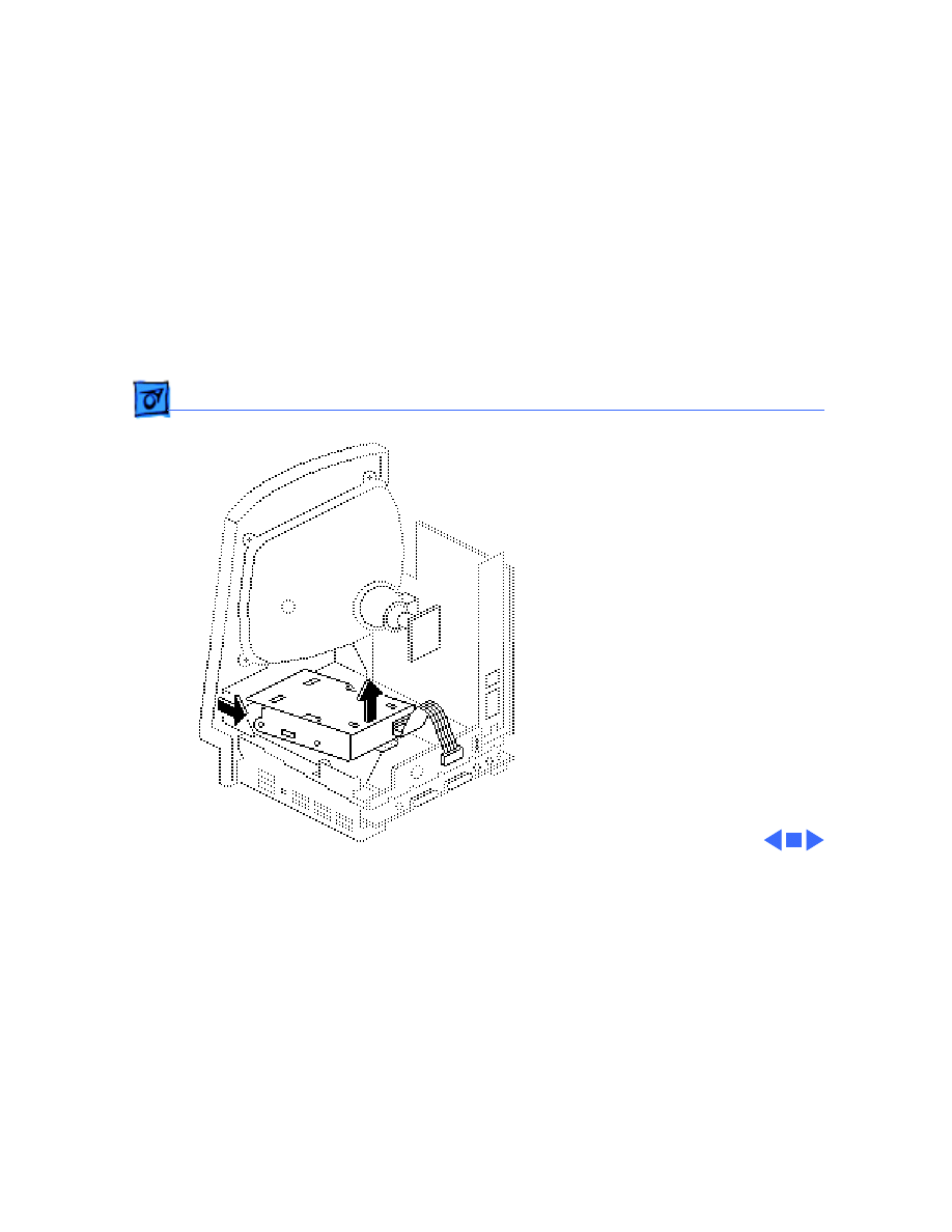
Take Apart
Hard Drive - 18
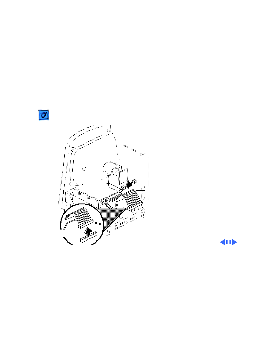
1 Disconnect the hard
drive data cable from the
logic board.
2 Disconnect the hard
drive power cable from
the power/sweep board.
Hard Drive
Data Cable
Hard Drive
Logic Board
Power Cable
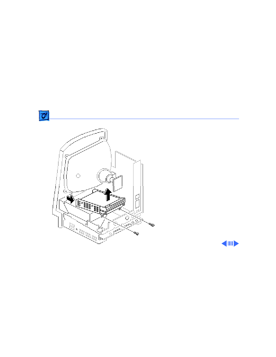
Take Apart
Hard Drive - 19
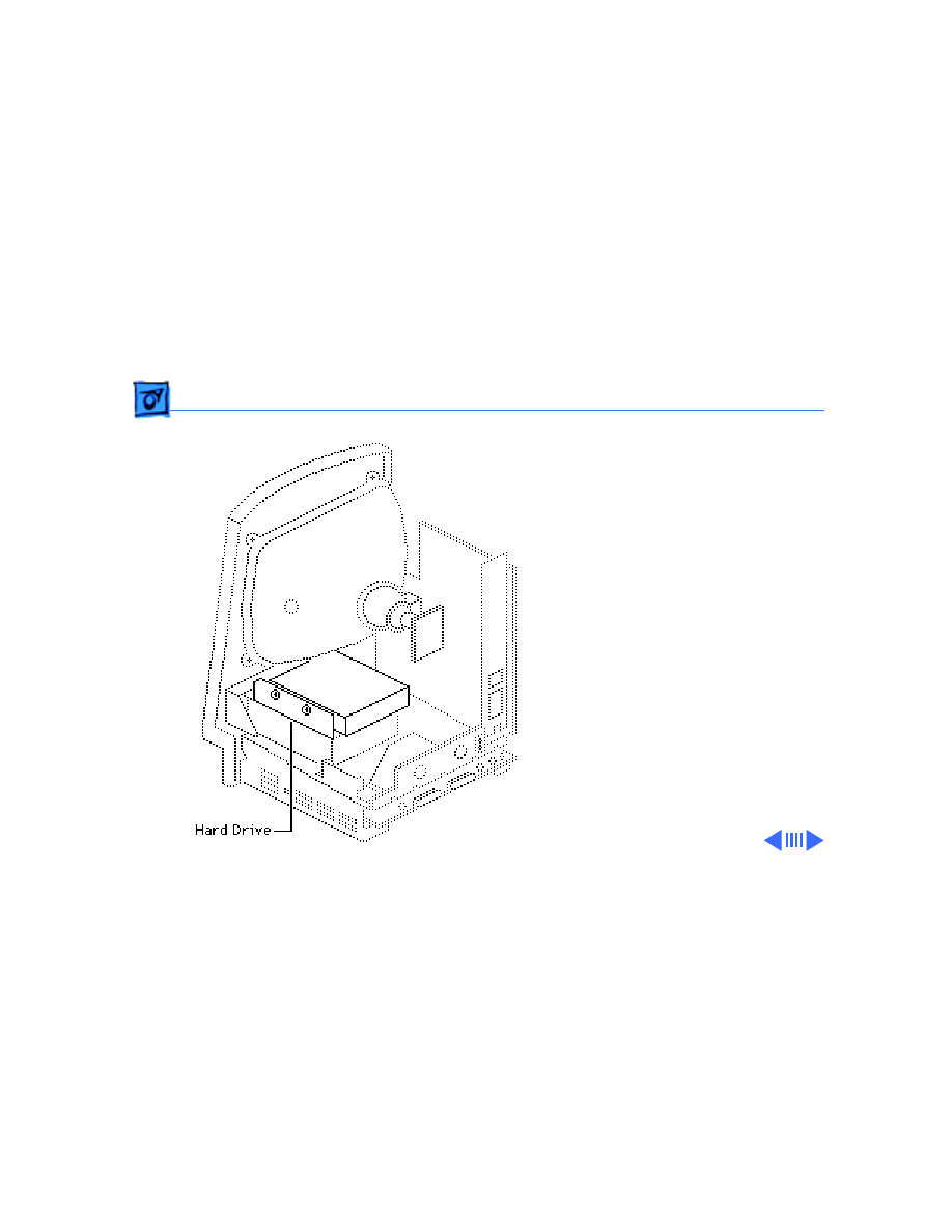
3 Remove the two Phillips
screws that secure the
hard drive housing to the
floppy drive housing and
lift out the hard drive
assembly.
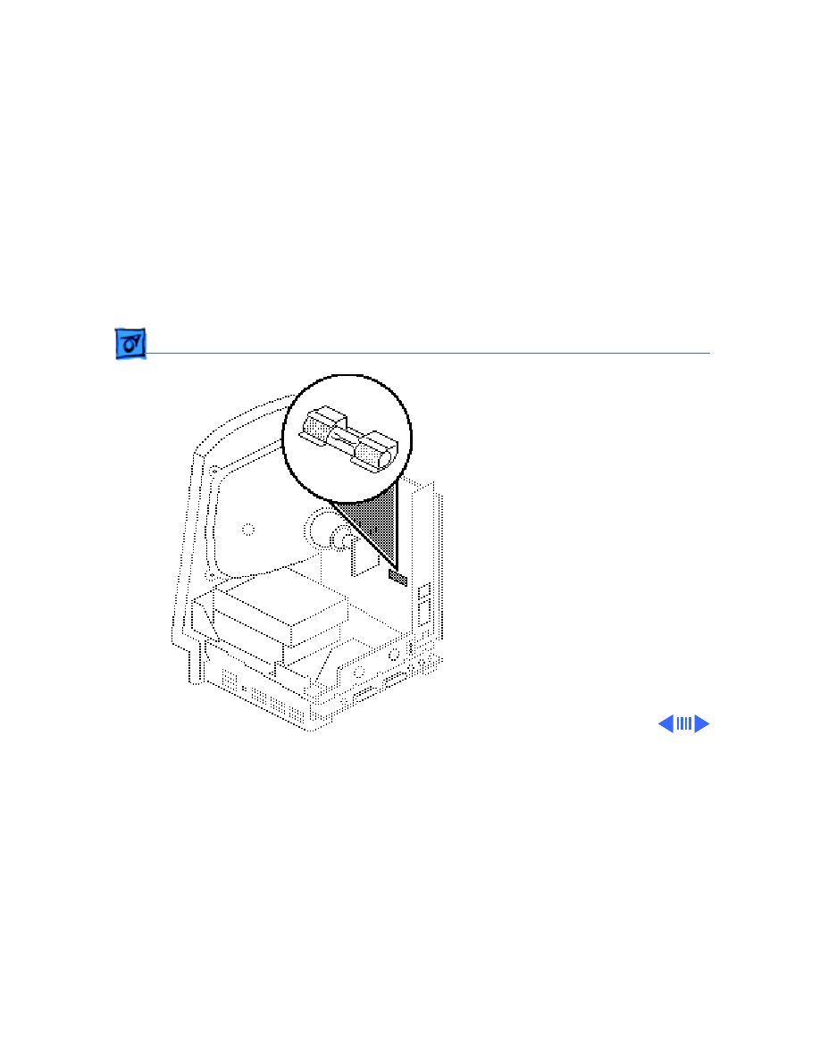
Replacement Note:
If you
are removing a hard drive
from the system but not
installing a new one, install
a SCSI terminator on the
logic board SCSI connector.
To insert the terminator,
line up the white key icon
with the notch in the cable
connector.

Take Apart
Hard Drive - 20
Replacement Note:
For
information on removing the
hard drive from the carrier
and returning drives,
cables, and carriers to
Apple, refer to Hardware/
Service Manuals/ SCSI Hard
Drives Manual.

Take Apart
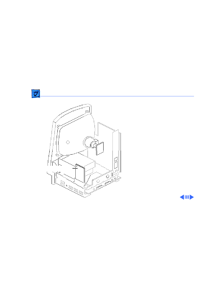
Floppy Drive - 21
Floppy Drive
Before you begin:
• Remove the cover
• Discharge the CRT
• Remove the hard drive
• Remove the logic board
±
Warning:
This product
contains high voltage and a
high-vacuum picture tube.
To prevent serious personal
injury or equipment
damage, review CRT safety
and discharge instructions
in Bulletins/Safety.
Caution:
To prevent ESD

Take Apart
Floppy Drive - 22
damage to components, wear
a grounding wriststrap.
Never use a grounding
wriststrap until after
discharging the CRT.
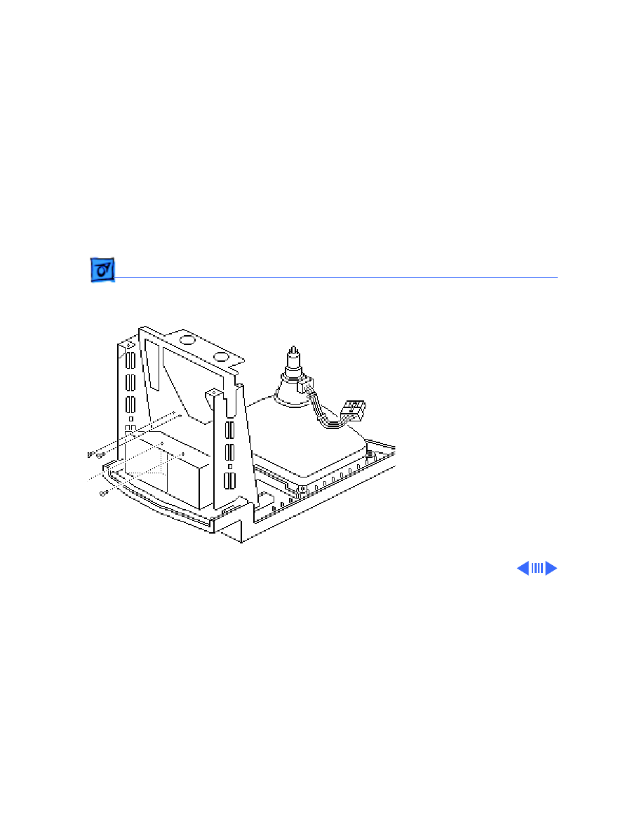
Take Apart
Floppy Drive - 23
1 Remove the four Phillips
screws that secure the
floppy drive housing to
the bottom of the chassis.
Take Apart
Floppy Drive - 24
2 Lift out the floppy drive
mechanism.
Replacement Note:
Before
you install a replacement
1.4 MB SuperDrive, you
must remove the dust shield.
Take Apart
Fan - 25
Fan
Before you begin:
• Remove the cover
• Discharge the CRT
• Remove the anode cap
• Remove the power/sweep
board
±
Warning:
This product
contains high voltage and a
high-vacuum picture tube.
To prevent serious personal
injury or equipment
damage, review CRT safety
and discharge instructions
in Bulletins/Safety.
Fan

Take Apart
Fan - 26
Caution:
To prevent ESD
damage to components, wear
a grounding wriststrap.
Never use a grounding
wriststrap until after
discharging the CRT.
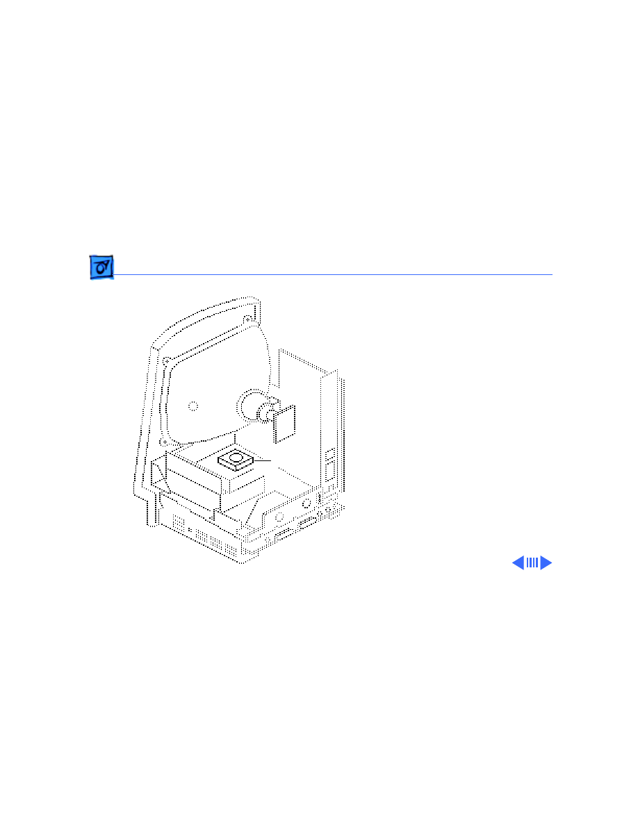
Take Apart
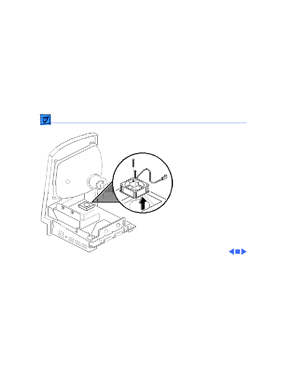
Fan - 27
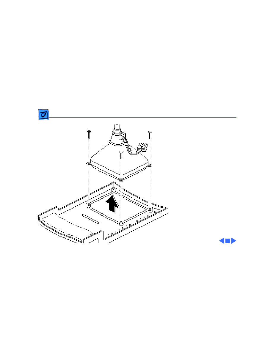
1 Using a small, stump-
handled Phillips
screwdriver, remove
the two screws that
mount the fan to the
chassis.
2 Lift out the fan.
Take Apart
CRT - 28
CRT
Before you begin:
• Remove the cover
• Discharge the CRT
• Remove the anode cap
• Remove the power/sweep
board
±
Warning:
This product
contains high voltage and a
high-vacuum picture tube.
To prevent serious personal
injury or equipment
damage, review CRT safety
and discharge instructions
in Bulletins/Safety.

Take Apart
CRT - 29
Caution:
To prevent ESD
damage to components, wear
a grounding wriststrap.
Never use a grounding
wriststrap until after
discharging the CRT.
Take Apart
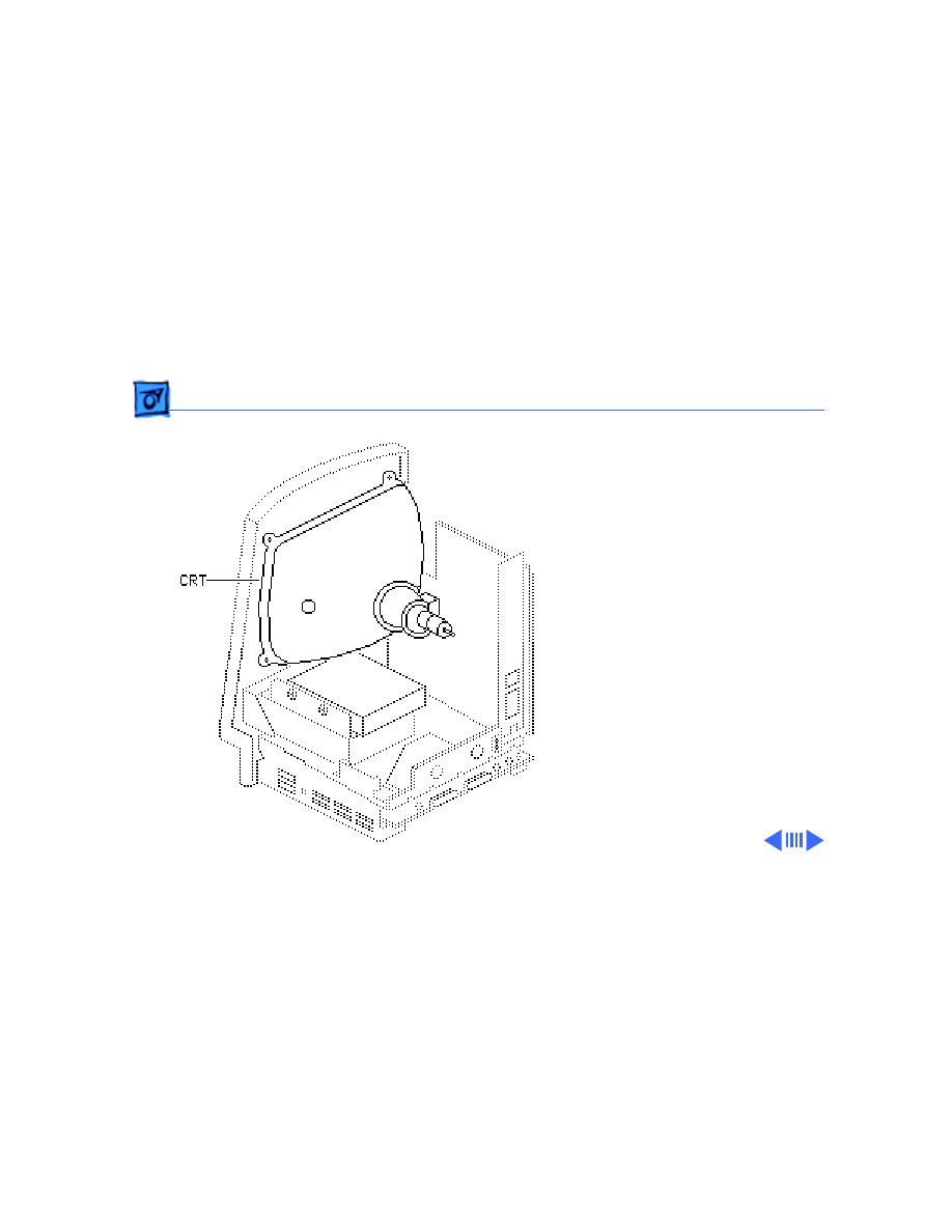
CRT - 30
1 Remove the three Torx
screws from the
corners of the CRT.
2 Carefully lift the CRT
free from the bezel.
Note:
The CRT yoke
assembly must be
compatible with the power/
sweep assembly, which is
available in two versions,
Rev A and Rev B. CRT yoke
assembly Rev A requires
power/sweep board Rev A.
CRT yoke assembly Rev B
requires power/sweep
board Rev B.

Take Apart
CRT - 31
Refer to “Power/Sweep
Board” in Take Apart to
identify CRT and power/
sweep revisions and to
verify compatibility.
Take Apart
Chassis & Front Bezel - 32
Chassis & Front
Bezel
Before you begin:
• Remove the cover
• Discharge the CRT
• Remove the anode cap
• Remove the power/sweep
board
• Remove the memory
expansion board
• Remove the logic board
• Remove the hard drive
• Remove the floppy drive
• Remove the fan

Take Apart
Chassis & Front Bezel - 33
±
Warning:
This product
contains high voltage and a
high-vacuum picture tube.
To prevent serious personal
injury or equipment
damage, review CRT safety
and discharge instructions
in Bulletins/Safety.
Take Apart
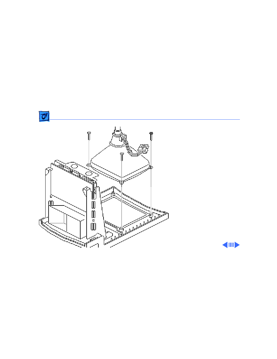
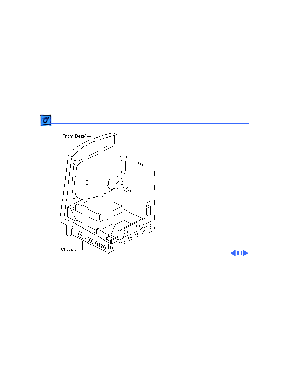
Chassis & Front Bezel - 34
1 Remove the four Torx
screws from the front
bezel.
2 Lift out the metal
chassis.
Take Apart
Chassis & Front Bezel - 35
3 Remove the three Torx
screws from the corner
of the CRT, and remove
the CRT.
Take Apart
Fuse - 36
Fuse
Before you begin:
• Remove the cover
• Discharge the CRT
±
Warning:
This product
contains high voltage and a
high-vacuum picture tube.
To prevent serious personal
injury or equipment
damage, review CRT safety
and discharge instructions
in Bulletins/Safety.

Take Apart
Fuse - 37
Caution:
To prevent ESD
damage to components, wear
a grounding wriststrap.
Never use a grounding
wriststrap until after
discharging the CRT.
Using a fuse puller or small
flat-blade screwdriver,
carefully remove the fuse
from its holder.
Service Source
K
Upgrades
Macintosh Classic/Classic II/
Performa 200

Upgrades
Memory Exp. Bd. - 1
Memory Exp. Bd.
Before you begin:
• Remove the cover
• Discharge the CRT
±
Warning:
This product
contains high voltage and a
high-vacuum picture tube.
To prevent serious personal
injury or equipment
damage, review CRT safety
and discharge instructions
in Bulletins/Safety.
Memory Expansion
Board

Upgrades
Memory Exp. Bd. - 2
Caution:
To prevent ESD
damage to components, wear
a grounding wriststrap.
Never use a grounding
wriststrap until after
discharging the CRT.
Upgrades
Memory Exp. Bd. - 3
Note:
The memory
expansion board is an option
for the Macintosh Classic
only. It contains 1 MB of
soldered RAM plus one pair
of SIMM connectors.
Carefully slide the memory
expansion board up to free it
from the logic board and the
chassis.
Upgrades
Memory Upgrade - 4
Memory Upgrade
Before you begin:
• Remove the cover
• Discharge the CRT
• Remove the memory
expansion board
±
Warning:
This product
contains high voltage and a
high-vacuum picture tube.
To prevent serious personal
injury or equipment
damage, review CRT safety
and discharge instructions
in Bulletins/Safety.
Memory Expansion
Board

Upgrades
Memory Upgrade - 5
Caution:
To prevent ESD
damage to components, wear
a grounding wriststrap.
Never use a grounding
wriststrap until after
discharging the CRT.

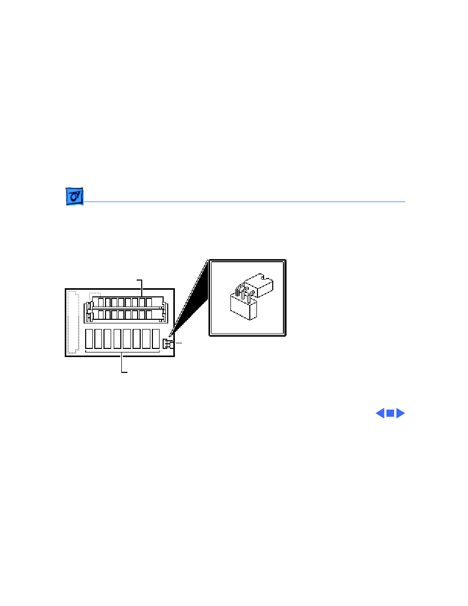
Upgrades
Memory Upgrade - 6
Note:
The memory
expansion board is an option
for the Macintosh Classic
only. It contains 1 MB of
soldered RAM plus one pair
of SIMM connectors. You can
upgrade the system further
by adding two 256K or two 1
MB SIMMs to the memory
expansion board and moving
the jumper. You must use
120-ns (or faster) SIMMs.
1 MB soldered RAM
Jumper
SIMM Connectors
Upgrades
Memory Upgrade - 7
Note:
Install the memory
board without additional
SIMMs for a 1 MB RAM
upgrade. Install two 256K
SIMMs onto the memory
expansion board for a 2.5
MB RAM upgrade or two 1
MB SIMMs for a 4 MB RAM
upgrade.
1 Install the SIMMs in the
SIMM slots on the
memory expansion
board.
2 Position the jumper as
shown.
1 MB soldered RAM
Jumper
SIMM Connectors
Upgrades
Classic II Upgrade - 8
Classic II Upgrade
Before you begin:
• Remove the cover
• Discharge the CRT
• Remove the logic board
±
Warning:
This product
contains high voltage and a
high-vacuum picture tube.
To prevent serious personal
injury or equipment
damage, review CRT safety
and discharge instructions
in Bulletins/Safety.
Caution:
To prevent ESD
damage to components, wear

Upgrades
Classic II Upgrade - 9
a grounding wriststrap.
Never use a grounding
wriststrap until after
discharging the CRT.

Upgrades
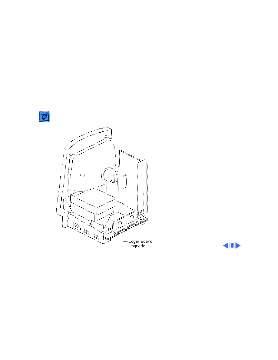
Classic II Upgrade - 10
Note:
A Macintosh Classic II
upgrade kit upgrades a
Macintosh Classic to a
Macintosh Classic II. The
upgrade kit includes a
Classic II logic board, a
Classic II cover, a
microphone, and an
accessory kit.
Upgrades
Classic II Upgrade - 11
Caution:
Take care that the
connections to the sound
output and sound input
ports are correct. Inserting
the wrong equipment into
the wrong port could damage
the Macintosh Classic II or
external equipment.
1 Install the Macintosh
Classic II logic board.
Upgrades
Classic II Upgrade - 12
2 Install the Classic II
cover.
3 Read the customer’s
original serial number
from the label on the
back of the old rear
housing and record the
number with indelible
ink or engrave it onto
the new rear housing.
Serial Number

Service Source
K
Additional Procedures
Macintosh Classic/Classic II/
Performa 200
Additional Procedures
Battery Verification - 1
Battery
Verification
Before you begin:
• Remove the cover
• Discharge the CRT
• Remove the logic board
±
Warning:
This product
contains high voltage and a
high-vacuum picture tube.
To prevent serious personal
injury or equipment
damage, review CRT safety
and discharge instructions
in Bulletins/Safety.
Caution:
To prevent ESD

Additional Procedures
Battery Verification - 2
damage to components, wear
a grounding wriststrap.
Never use a grounding
wriststrap until after
discharging the CRT.
Additional Procedures
Battery Verification - 3
±
Warning:
If handled or
discarded improperly, the
lithium battery in the
computer could explode.
Review battery handling and
disposal instructions in
Bulletins/Safety.
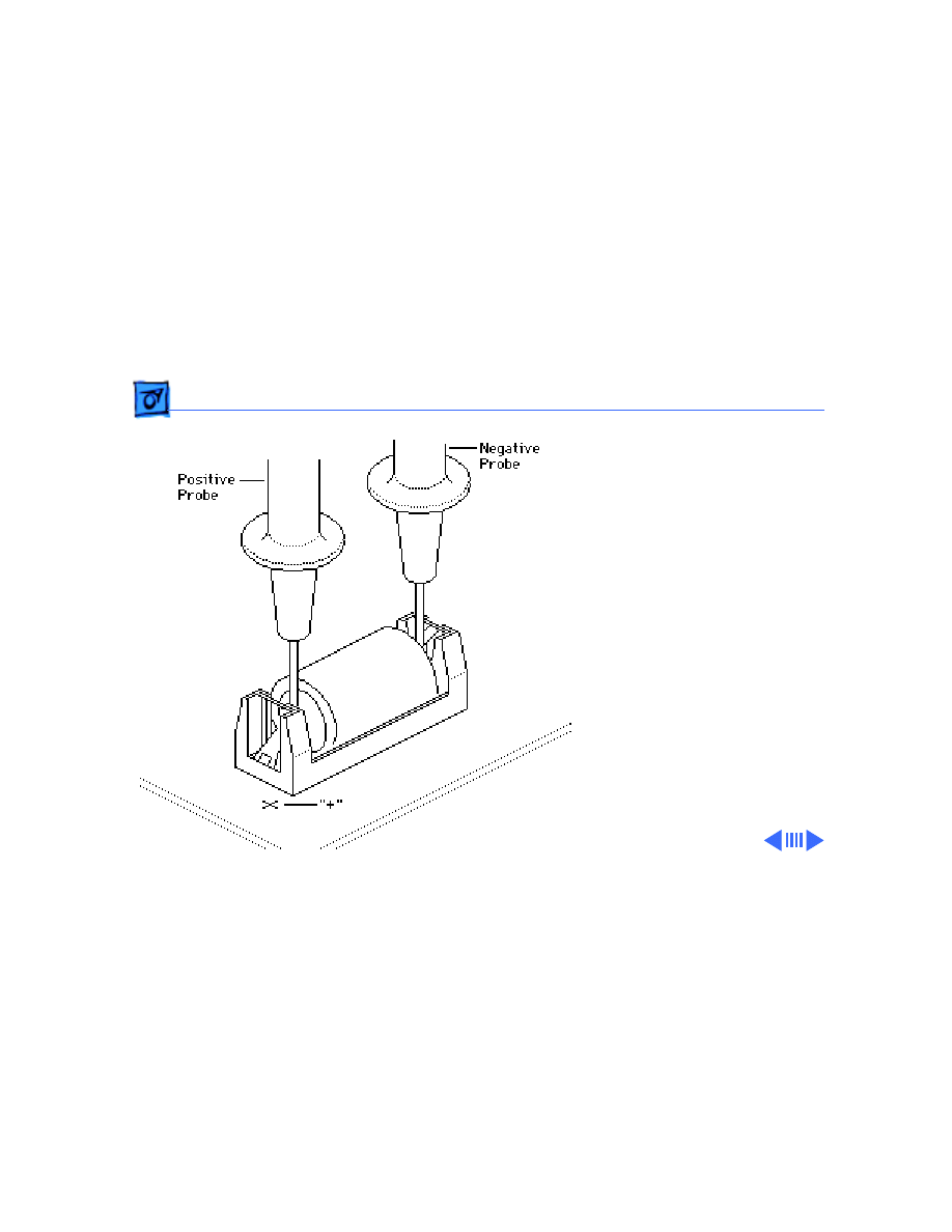
1 Set the voltmeter range
to the10 volts DC scale.
2 Hold the positive probe
of the voltmeter to the
positive “+” side of the
battery. Hold the ground
probe of the voltmeter to
the negative (-) side of
the battery.

Additional Procedures
Battery Verification - 4
3 If the battery voltage is
below 3.0 volts, replace
the battery. See
“Battery Replacement”
in this chapter.

Additional Procedures
Battery Replacement - 5
Battery
Replacement
Before you begin:
• Remove the cover
• Discharge the CRT
• Remove the logic board
±
Warning:
This product
contains high voltage and a
high-vacuum picture tube.
To prevent serious personal
injury or equipment
damage, review CRT safety
and discharge instructions
in Bulletins/Safety.

Additional Procedures
Battery Replacement - 6
Caution:
To prevent ESD
damage to components, wear
a grounding wriststrap.
Never use a grounding
wriststrap until after
discharging the CRT.
Additional Procedures
Battery Replacement - 7
±
Warning:
If handled or
discarded improperly, the
lithium battery in the
computer could explode.
Review battery handling and
disposal instructions in
Bulletins/Safety.
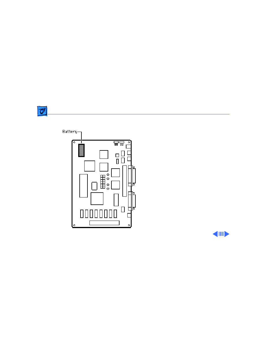
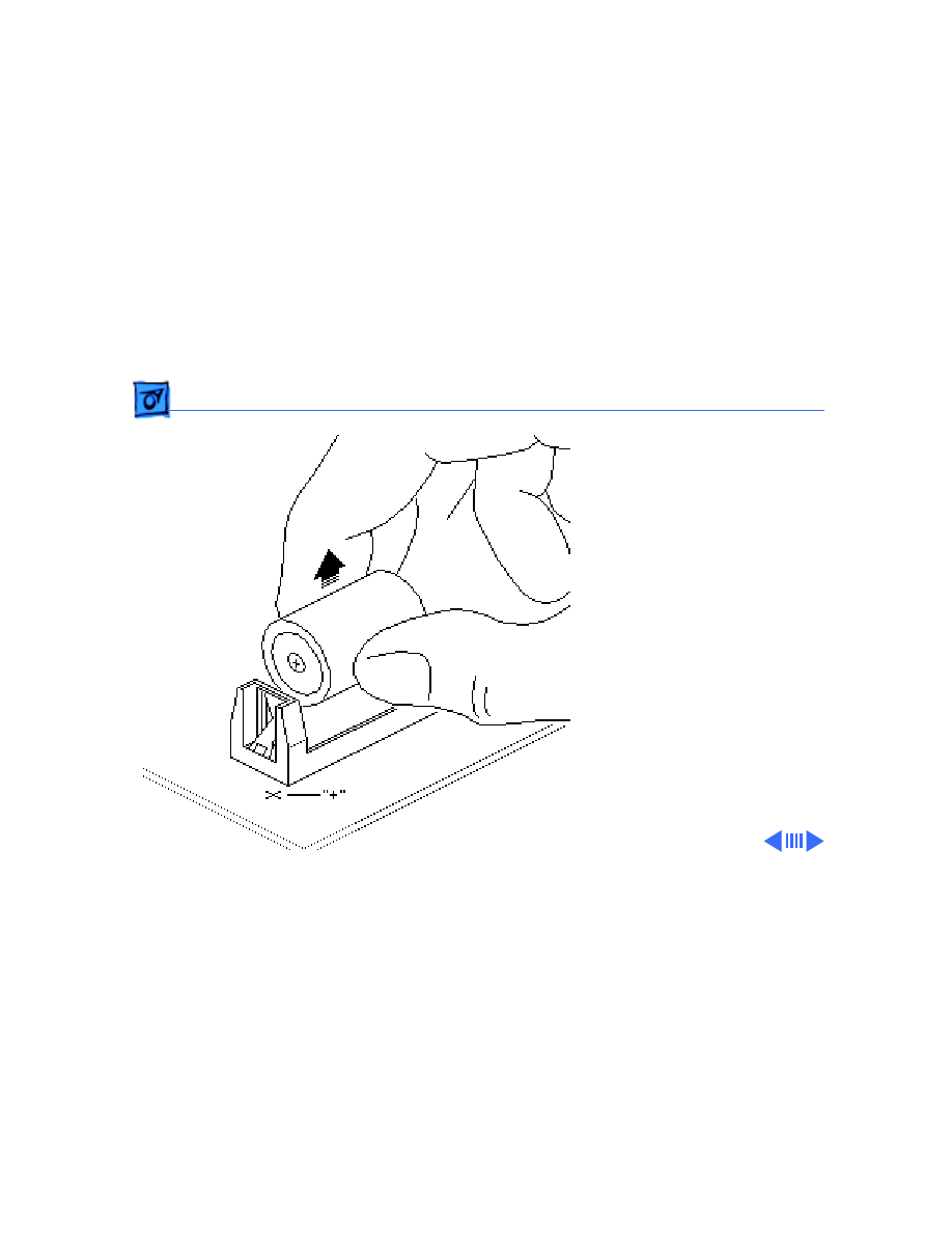
1 Pull the old battery out
of the battery holder.
2 Replacement Note:
Orient the new battery
so that the end marked
“+” matches the “+” on
the logic board, and
insert the battery into
the battery holder.

Additional Procedures
Battery Replacement - 8
Note:
For information about
properly disposing of the old
battery, refer to battery
disposal instructions in
Bulletins/Safety.
Service Source
K
Adjustments
Macintosh Classic/Classic II/
Performa 200
Adjustments
Light Meter Setup - 1
Light Meter Setup
This topic covers setup for
three light meter models:
R77, L-248, and 246.
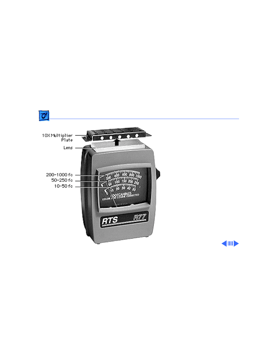
Model R77 (Apple part
number 076-0310) is the
newest model available.
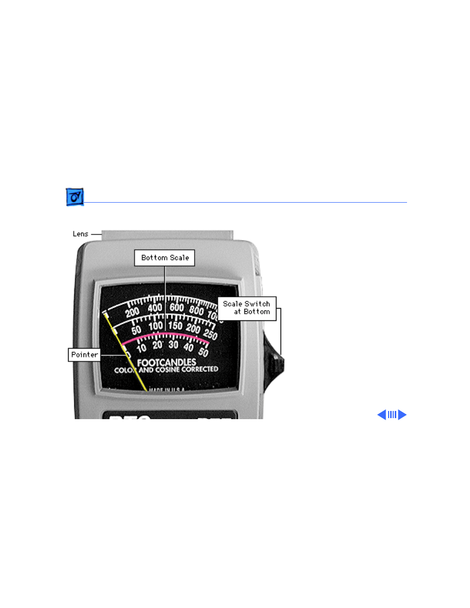
Model R77
The R77 light meter is
capable of reading luminance
from 10 to 1,000
footcandles (fc).
Before you begin, remove
the 10X multiplier plate
Adjustments
Light Meter Setup - 2
from the lens.
Three scales are shown on
the light meter:
• 200-1000 fc
• 50-250 fc
• 10-50 fc
Because display screen
luminance typically ranges
from 10 to 50 fc, take
readings from the bottom
scale only.
Adjustments
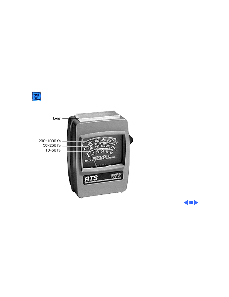
Light Meter Setup - 3
To measure a display
screen’s luminance,
1 Set the scale switch to
the bottom position (to
set up the 10-50 fc
scale).
2 Place the lens against the
middle of the screen and
read the bottom scale.
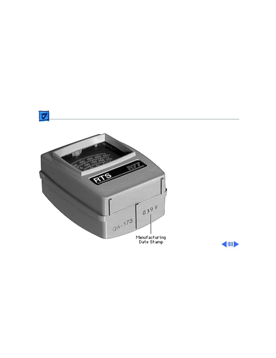
Note:
When the light meter
is not in use, slide the scale
switch to its top position,
and store the meter in its
protective case.
Important:
If you suspect the
light meter is giving false
Adjustments
Light Meter Setup - 4
readings, verify the
readings with a known-good
light meter or photometer.
Also check the age of the R77
light meter by its four-digit
manufacturing date stamp
(such as 0398 for March
1998).
Caution:
Dropping the
meter can permanently
damage its accuracy. A
shock-damaged meter might
read incorrectly or its
pointer may not drop to
zero.
Adjustments
Light Meter Setup - 5
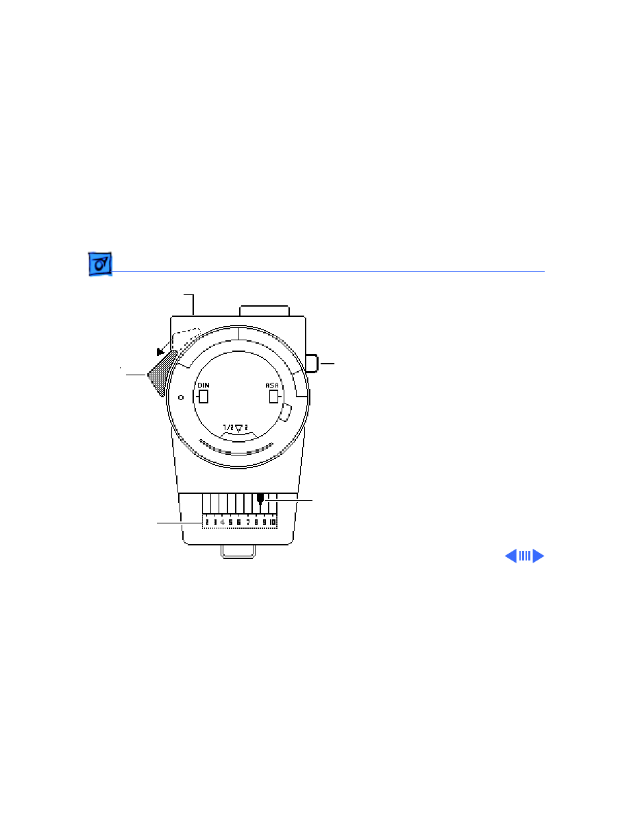
Model L-248
1 Press the red button on
the back of the light
meter. If the reading is
out of the red area,
replace the battery.
2 Move the side switch to
its lower position so that
the scale reads 2 through
10.
3 Uncover the lens of the
meter.
4 Place the lens against the
middle of the screen and
press the read button to
read the scale.
Read
Red Area
Scale
Side
Lens
Button
Switch
Adjustments
Light Meter Setup - 6
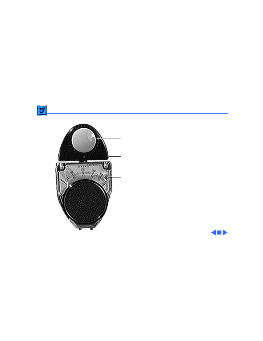
Model 246
1 Remove the metal slide,
if installed, from the
top of the light meter.
2 Install the white lens
with the red dot.
3 Rotate the swivel head
so the lens of the meter
faces the monitor.
4 Place the lens against the
middle of the screen and
read the scale.
Lens
Swivel Head
Scale
Adjustments
Video - 7
Video
Note:
After you replace the
CRT or power/sweep board,
you may need to perform
video adjustments.
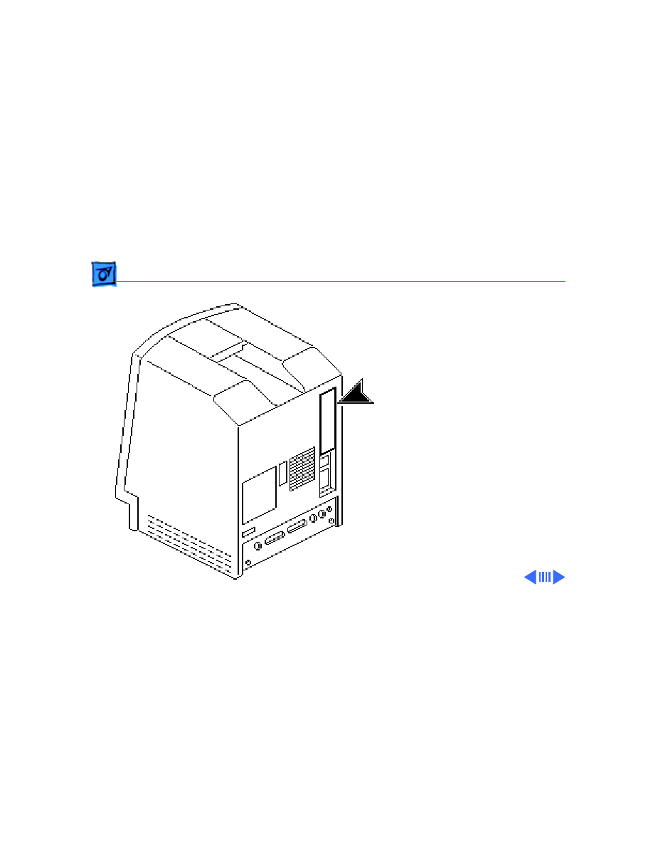
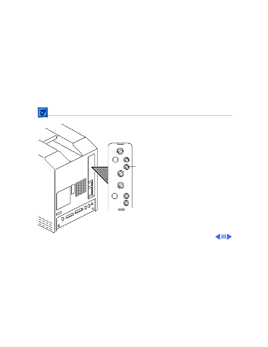
1
Caution:
Because you
must make adjustments
from the rear of the
computer, position a
mirror to view the
computer screen.
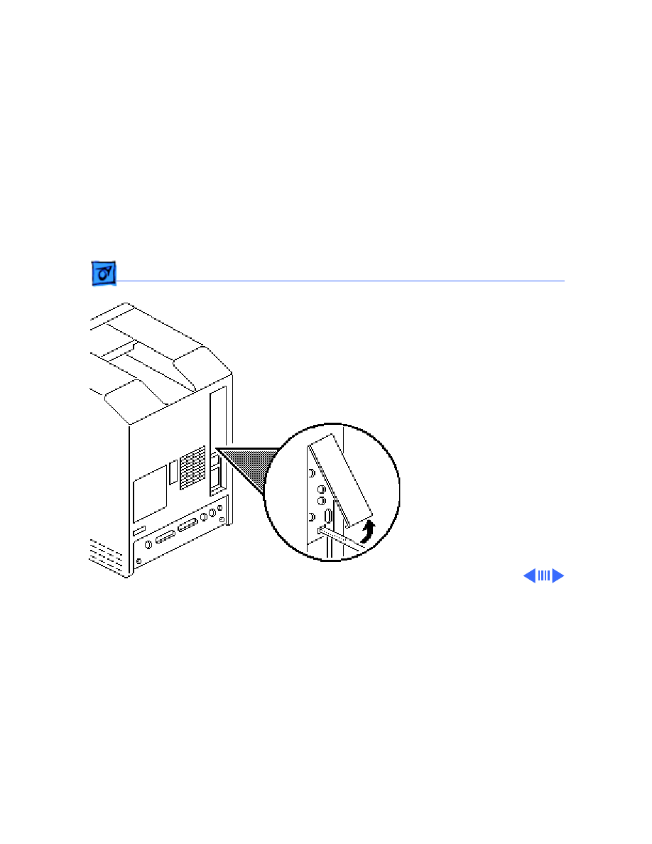
Adjustments
Video - 8
2 Using a small flat-blade
screwdriver, depress
the center tab and lift
out the service door.
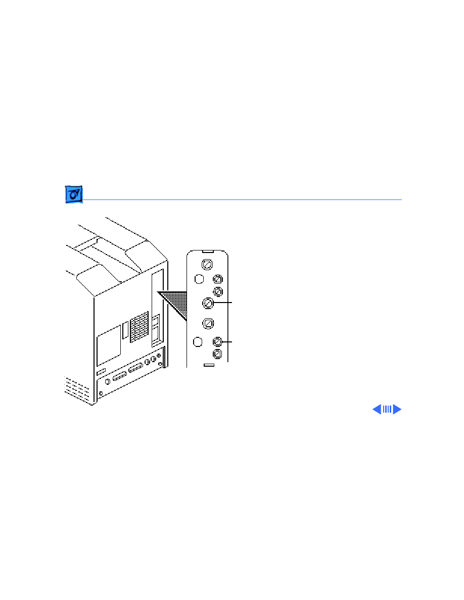
Adjustments
Video - 9
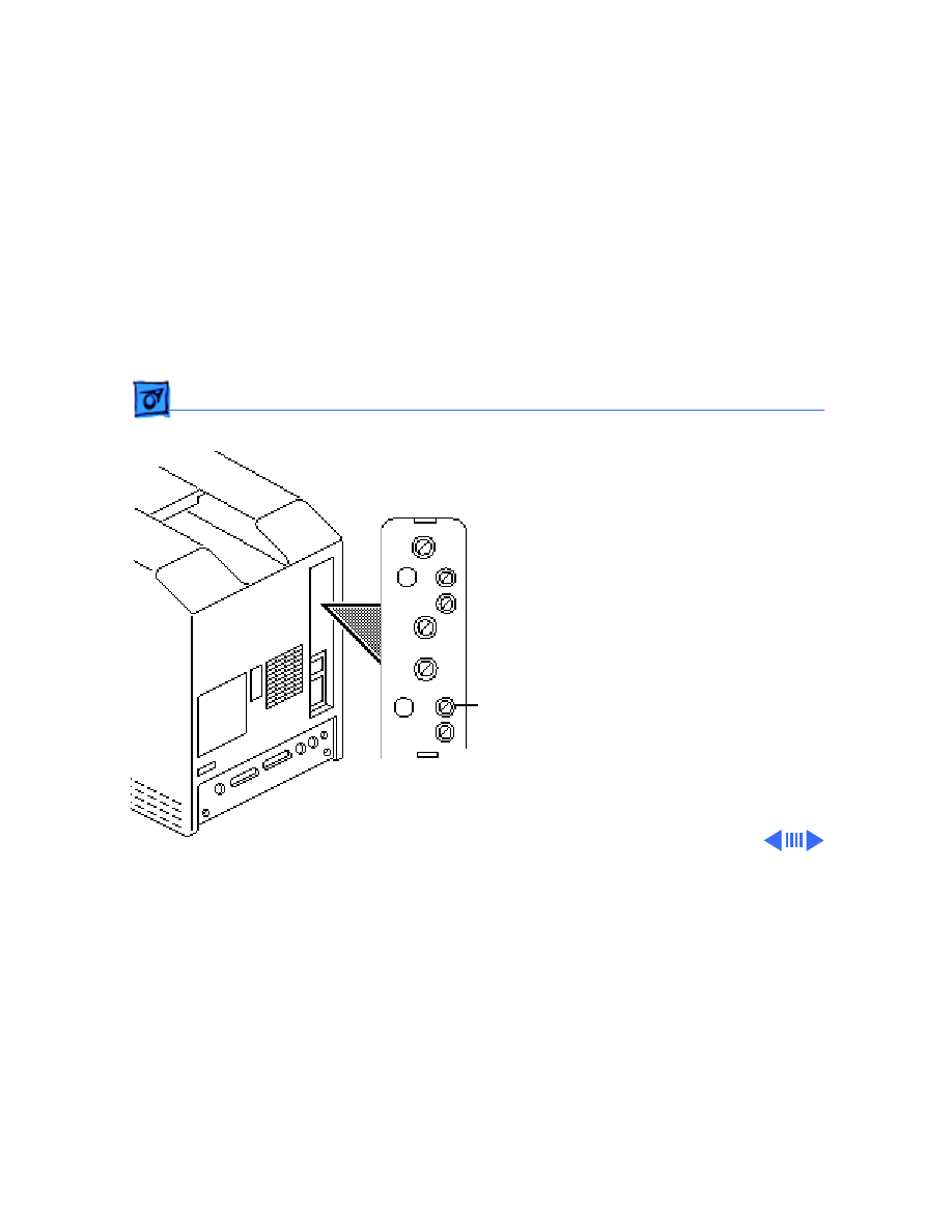
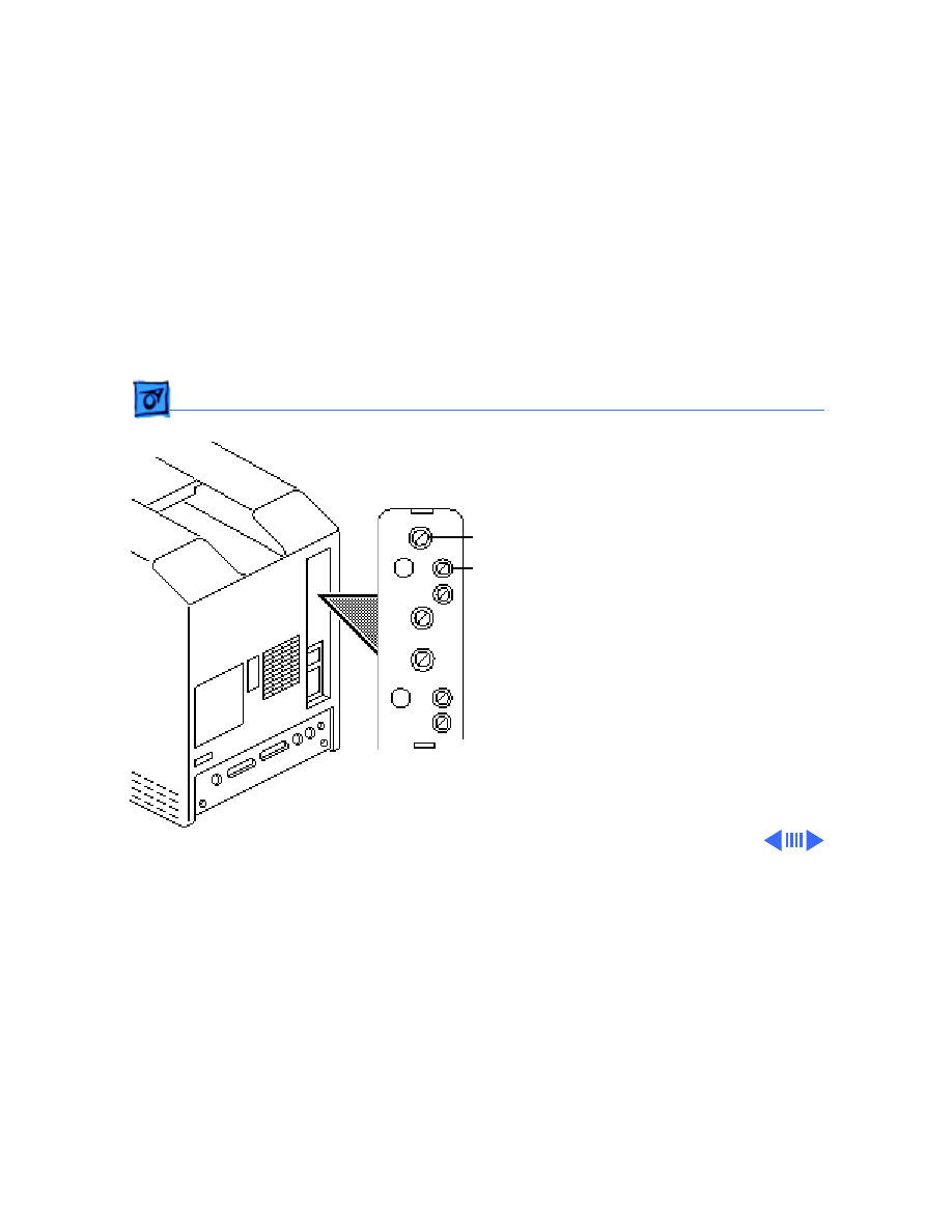
Brightness & Contrast
Important:
Readings from
light meters may differ
between models. Please note
the type of meter you are
using (Model R77, L-248,
or 246) before making an
adjustment. (See “Light
Meter Setup.”)
Note:
Be sure the computer
has been on for at least 30
minutes.
1 Run the Display Service
Utility from the Utilities
folder on the MacTest
Pro CD.
Contrast
Brightness
(PL2)
(PL4)
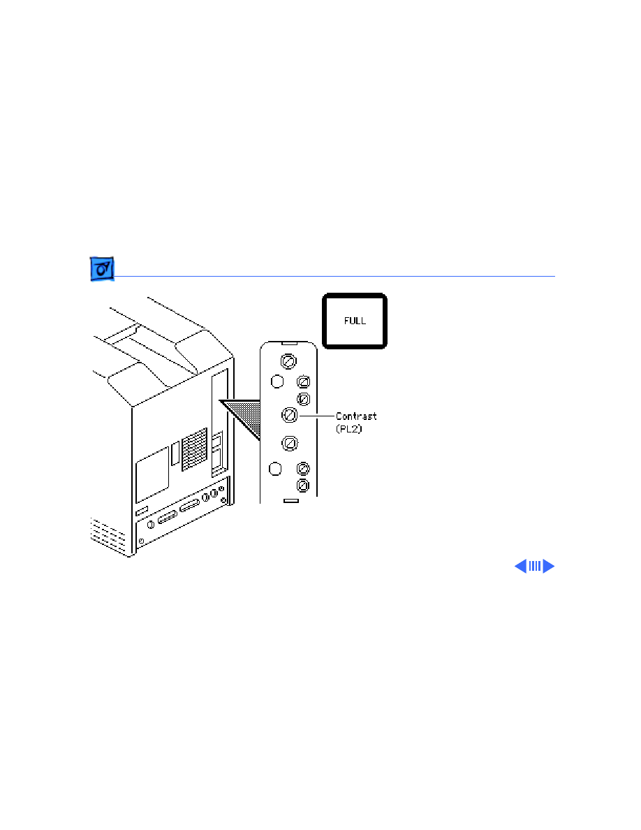
Adjustments
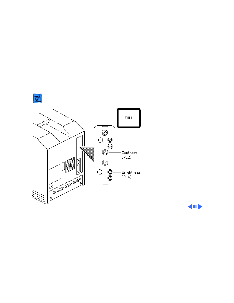
Video - 10
2 From the pattern
selections screen, select
the Full brightness
screen.
3 Hold the light meter
lens against the center of
the screen.
4 Using an insulated flat-
blade screwdriver,
adjust the contrast
control until you
measure luminance at
40 foot lamberts (± 3
foot lamberts), which on
the light meter is
• Model R77: 29 on the
bottom scale
Adjustments
Video - 11
• Model L-248: 10 to
11 on the 10-18 scale
• Model 246: 29 on the
red scale
Important:
Over time,
light meter tolerance can
vary. If you doubt your
meter’s accuracy,
verify the readings with
a known-good light
meter or photometer.
5 Press a key to return to
the pattern selections
screen. Select the Half
brightness screen.
Adjustments
Video - 12
6 Using a plastic hex
alignment tool, adjust
the brightness control
until the luminance at
the center of the screen
measures 5 foot
lamberts (± 1 foot
lambert), which on the
light meter is
• Model R77: halfway
between zero and 10
on the bottom scale
• Model L-248: high
end of 7 on the 2-10
scale
• Model 246: 5 on the
red scale
Brightness
(PL4)
Adjustments
Video - 13
7 Press a key to return to
the pattern selections
screen. Select the Full
brightness screen.
8 Recheck the luminance at
the center of the screen:
• Model R77: 29 on the
bottom scale
• Model L-248: 10 to
11 on the 10-18 scale
• Model: 246: 29 on the
red scale
If the light meter reading
does not match the
measurement shown, repeat
the brightness & contrast
procedure.
Adjustments
Video - 14
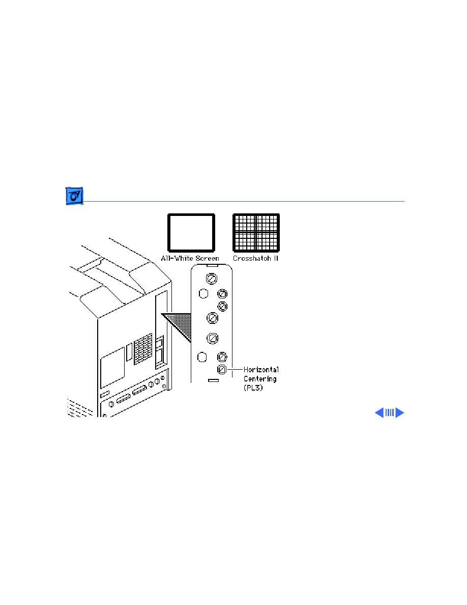
Centering
1 Run the Display Service
Utility.
2 Select the Crosshatch
pattern or the All-White
pattern.
3 Using the plastic hex
alignment tool, adjust
the horizontal centering
control to center the
display image
horizontally within the
bezel.
Adjustments
Video - 15
4 Using the plastic hex
alignment tool, adjust
the vertical centering
control to center the
image vertically within
the bezel.
Vertical
Centering
(PF2)
Adjustments
Video - 16
Size Adjustments
1 Using the plastic hex
alignment tool and a
ruler, adjust the
horizontal size control
until the display image
is 7 inches (177.8
mm) wide.
2 Using the plastic hex
alignment tool, adjust
the vertical size control
until the display image
is 4.7 inches (119.38
mm) high.
Horizontal
Size (LL2)
Vertical
Size (PF1)
Adjustments
Video - 17
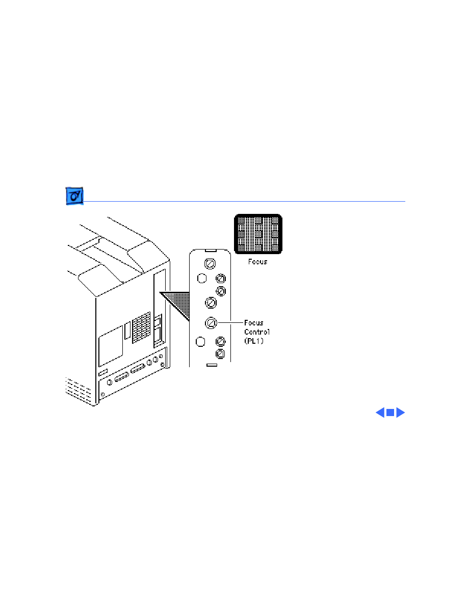
Focus Adjustments
1 Display the Focus test
pattern using Display
Service Utility.
2 Using an insulated flat-
blade screwdriver,
adjust the focus control
for the best overall
focus.
Adjustments
Yoke - 18
Yoke
Before you begin:
• Remove the cover
• Discharge the CRT
±
Warning:
This product
contains high voltage and a
high-vacuum picture tube.
To prevent serious personal
injury or equipment
damage, review CRT safety
and discharge instructions
in Bulletins/Safety.
Yoke

Adjustments
Yoke - 19
Caution:
Because you must
make adjustment from the
rear of the computer,
position a mirror to view
the computer screen. Do not
reach around the computer
to adjust collars and rings.
Note:
After you replace the
CRT, you may need to adjust
the yoke.

Adjustments
Yoke - 20
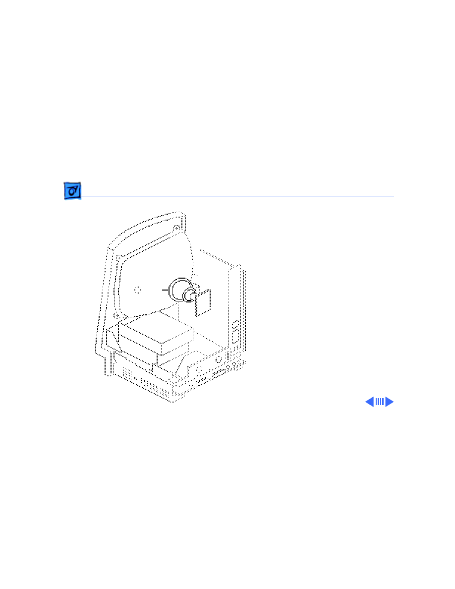
1
Note:
If glue holds the
yoke collar in place, use
an art knife to cut
through the glue.
Loosen the yoke clamp
screw two or three
turns.
2 Switch on the computer.
Yoke Collar
Yoke Clamp
Screw

Adjustments
Yoke - 21
3 With one hand, grasp
the plastic spokes of the
yoke collar and rotate
the yoke collar until the
top and bottom edges of
the picture are parallel
with the top and bottom
of the bezel.
Plastic Spokes
Yoke Collar
Adjustments
Yoke - 22
4 Switch off and unplug the
computer.
5 Discharge the CRT.
6
Caution:
Do not
overtighten the yoke
clamp screw.
Hold the plastic collar
in position and carefully
tighten the yoke clamp
screw so that the collar
cannot slip.
Yoke Collar
Yoke Clamp
Screw

Adjustments
Yoke - 23
7 Replace the cover and
switch on the computer.
Make sure the top and
bottom edges of the
picture are parallel with
the top and bottom of the
bezel.
Adjustments
Yoke - 24
Centering Ring
Adjustment
1
Note:
If glue holds the
yoke collar in place, use
an art knife to cut
through the glue.
Switch on the computer.
2 To center the picture
within the bezel: Hold
the front centering ring
steady and move the
rear ring; then hold the
rear centering ring
steady and move the
front ring.
Centering Rings
Service Source
K
Exploded View
Macintosh Classic/Classic II/
Performa 200
Exploded View
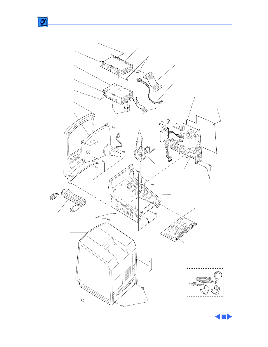
1
Exploded View
Hard Drive
661-0216 (40 MB)
444-6104
Hard Drive
Carrier
805-0950
Floppy Drive
Carrier
805-5050
Floppy Drive
661-0474
460-3400
Front Beze
i630-5825
CRT and Yoke
Assembly
076-0546
462-4100
462-4100
416-1330
Hard Drive
Data Cable
(590-0211)
Hard Drive
Power Cable
590-0521
Insulator
815-1216
Floppy Drive
Cable
590-0167
830-0270
490-0001
Fan
Power/Sweep Board
661-0597 (110V, Rev. A)
661-0599 (220V, Rev. A)
661-0651 (110V, Rev. B)
661-0652 (220V, Rev. B)
426-1001
426-1007
Microphone
699-5103
426-1001
Chassis
with Plenum
630-5818
Lithium Battery
742-0011
Logic Board
661-0596 (1 MB, Classic)
661-0672 (2MB, Classic II, P200)
Rear
Housing
Access
Door
815-1195
Rear
Housing
630-6045
435-5002
865-0051
Power
Cable
590-0380
Document Outline
- Macintosh Classic/Performa 200
- Basics
- Specifications
- Troubleshooting
- Take Apart
- Upgrades
- Additional Procedures
- Adjustments
- Exploded View
Wyszukiwarka
Podobne podstrony:
astra classic ii tech
Amiot P , Marleau L Mecanique classique II (Laval Uni lectures, 1997)(fr)(137s)(1)
astra classic ii tech
Phase Linear 200 II
TWK - KOLOS II sem, X. Performanse glob. i mędzy. TO NIE JET WSZYSTKO!
200, Elektrotechnika AGH, Semestr II letni 2012-2013, Fizyka II - Laboratorium, laborki, Fizyka II -
Happening i performance w kontek cie, Notatki I i II rok hs, Sztuka współczesna
200-04, ZiIP Politechnika Poznańska, Fizyka II, Ćwiczenia
200 07, ZiIP Politechnika Poznańska, Fizyka II, Ćwiczenia
Phase Linear 200 II
Phase Linear 200 II
więcej podobnych podstron