
7
th
European Meeting on Chemical Industry and Environment
EMChIE 2015
Tarragona, 10-12 June 2015
ATEX (Explosive Atmosphere) Human-Machine-Interaction Integrated Safety
Assessment Methodology
Jie Geng
1,2
, Salvina Murè
1
, Gianfranco Camuncoli
1
, Micaela Demichela
2
1
ARIA s.r.l. – Corso Mediterraneo 140 -10129 Torino, Italia
2
SAfeR, Dipartimento di Scienza Applicata e Tecnologia, Politecnico di Torino, Corso Duca degli
Abruzzi, 24 – 10129 Torino, Italia
e-mail: jie.geng@aria.to.it
Abstract
ATEX (explosive atmosphere) risk assessment is required when any equipment or protective systems
are intended for use in potentially explosive atmospheres. However, when reviewing the whole ATEX
risk assessment procedures and their results, despite many operations on plant and equipment
containing dangerous substances are performed by operators, the human and organizational influences
are neglected. With the growing complexity, increased automation and functional sophistication high-
technology systems, apart from some events caused by an unusual or unforeseeable manifestation,
such as an earthquake, in the majority of cases, human became the main or sometimes even the only
cause. The practical need for Human Reliability Analysis (HRA) has grown as part of the requirement to
calculate more precisely the probability of an accident and to improve the understanding of human
action as a part of system design. This study aims to propose an ATEX Human-Machine-Interaction
(HMI) Integrated Safety Assessment (ISA) methodology with integration of the Human Reliability
Analysis into the Probabilistic Safety Assessment (PSA), in order to be able to analyse the HOFs
influences on ATEX hazards.
Keywords: ATEX Risk Assessment, Human-Machine Interaction (HMI), Integrated Safety Assessment
(ISA)
INTRODUCTION
ATEX (explosive atmosphere) risk assessment is required when any equipment or protective
systems are intended for use in potentially explosive atmospheres. The standard ATEX risk evaluation
result relies on a semi-quantitative approach which is based on the following indexes: probability of an
explosive atmosphere formation, probability of the presence of an effective ignition source,
consequences. However, when reviewing the whole ATEX risk assessment procedures and their
results, although many operations are performed by operators, influences from human and
organizational factors (HOFs) are mostly neglected. (e.g. maintenance activity, as in Demichela et al.,
2014, that could even bring to major accidents, as in Piccinini & Demichela, 2012). The ATEX-HMI
(Human-Machine Interaction)-ISA (Integrated Safety Assessment) methodology is proposed in this
paper, in order to be able to analyse the HOFs influences on ATEX hazards.
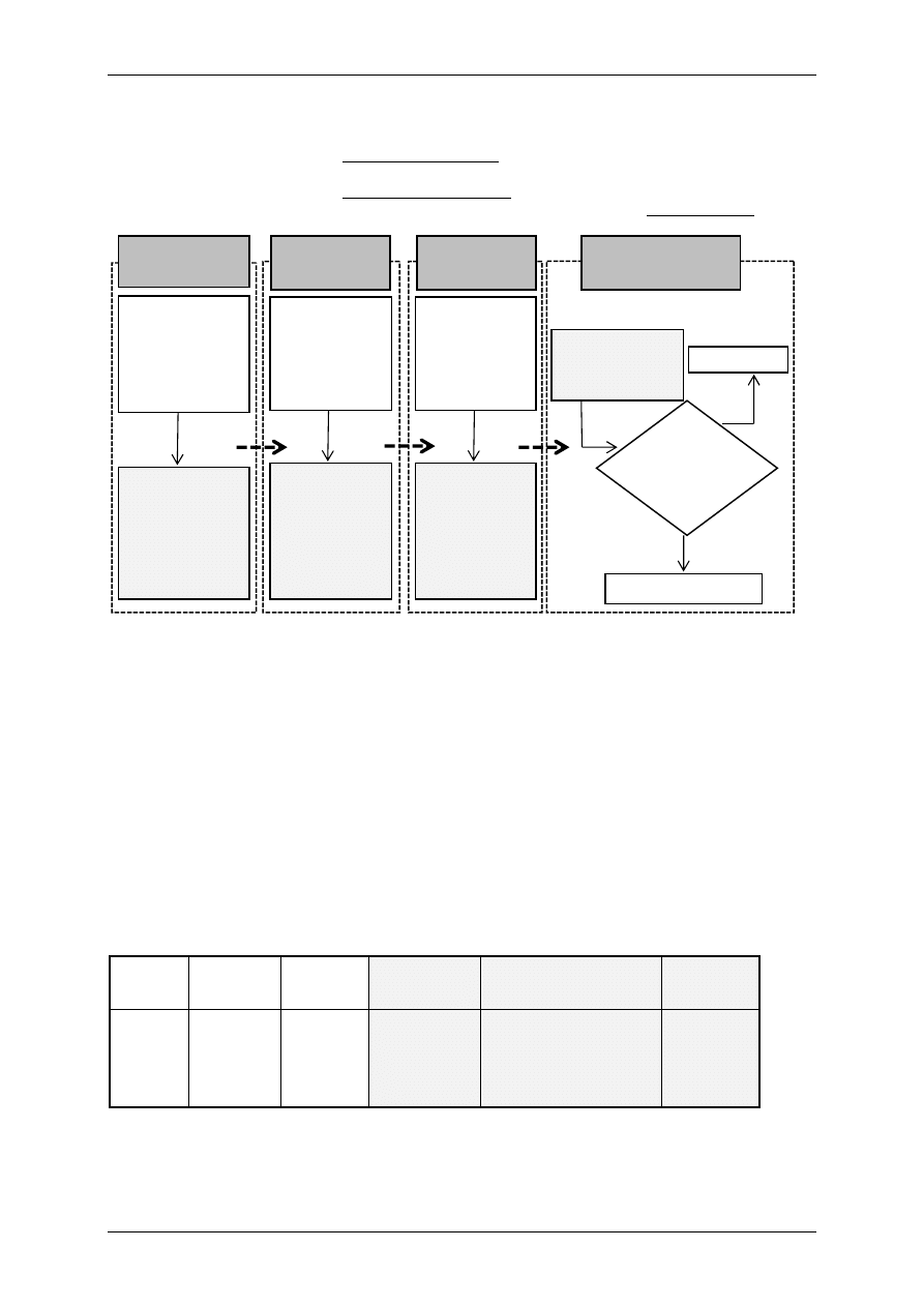
The ATEX-HMI-ISA methodology needs to face to two challenges: 1) identification of the HOFs
influence on the ATEX risk assessment under the Human-Machine Interaction (HMI) system; 2)
quantification of the HOFs influence with the Integrated Safety Assessment (ISA). To deal with
challenge 1 & 2, the ATEX-HMI-ISA methodology is developed from the standard ATEX risk
assessment methodology (see Figure 1), which consists of four steps: 1) Area Classification, 2)
Ignition Source Identification, 3) Consequence Analysis, and 4) ATEX Risk Evaluation.
Human-Machine Interaction (HMI): Apart from the step 3 (Consequence Analysis) - that is highly
relied on the results from the area classification (step 1), and the step 4 (ATEX Risk Evaluation) - that
needs to integrate step 1-3, the step 1 (Area Classification) and the step 2 (Ignition Source
Identification) are the main considerations of the HOFs integration in the ATEX-HMI-ISA methodology.
Integrated Safety Assessment (ISA): Once HOFs influence in each step is identified, ISA aims to
provide the method for “how to quantify the HOFs influence”. Probabilistic Safety Assessment (PSA) is
introduced to be able to quantify the risk with two parts: 1) transferred probability from initial results of
each step in the standard ATEX risk assessment; and 2) Human Error Probability (HEP) from the
Human reliability analysis (HRA). HRA, as one of the important categories of the human factor
techniques, aims to identify and quantify human error. However, in this paper, we are not aiming to
explain how HRA works, but focusing on how to integrate HRA into the developed methodology. Since
the previous works of the HRA integration were based on the Area Classification (Geng et al., 2014;
Geng et al., 2015), in this paper, the step 2 (Ignition Source Identification) are explained in more
details than the step 1 (Area Classification) as an example.
Further, the final ATEX risk evaluation remains in the ATEX-HMI-ISA methodology, which is still
using semi-quantitative values to calculate (R
HOF
=P
HOF
*C
HOF
*D’
HOF
). However, those semi-quantitative
values (P
HOF
, C
HOF
, and D’
HOF
) derived from each step are determined by the PSA. In the end, the final
7
th
European Meeting on Chemical Industry and Environment
EMChIE 2015
Tarragona, 10-12 June 2015
ATEX risk evaluation result (R
HOF
) is influenced by the modified values of P
HOF
, C
HOF
and D’
HOF
. As
mentioned above, two situations coming from the HOFs influence may occur:
1) In case of the plant with the sufficient management,
Result (ATEX-HMI-ISA) = Result (Standard ATEX Risk Assessment)
2) In case of the plant with the insufficient management,
Result (ATEX-HMI-ISA) = Result (Standard ATEX Risk Assessment + HOFs Influence)
Figure 1. The framework of ATEX-HMI-ISA methodology (Geng, et al., 2014)
STEP 1 OF THE ATEX-HMI-ISA METHODOLOGY: AREA CLASSIFICATION
The standard ATEX Area Classification analysis is referred to IEC 60079-10 (for gas) and IEC
61241-10 (for dust). For the specific application in countries, some guidelines provide the detailed
procedures, such as CEI 31-35 and CEI 31-56. It generally includes: 1) the identification of release
sources - each item of the process equipment which contains a flammable material is considered as a
potential release source; 2) assessment of the internal and external zones of the identified emission
sources, on the basis of the degree of release, the release rate, concentration, velocity, ventilation
and other factors (such as prevention measures). In the previous study (Geng et al., 2014; Geng et al.,
2015), the HOFs was identified as a type of prevention measures or barriers in the external zone
prediction part. The barriers can be technical barriers or HOFs barriers. In Area Classification of the
ATEX-HMI-ISA methodology, these barriers were concerned with potential probability of failure (for
example, the probability of the technical barrier failure P
tbf
,
and/or the HEP). In the end, the Probability
of Barrier Failure (PBF) was integrated into the final PSA, in order to see the difference of the zone
prediction with and without barriers‘ consideration (see Table 1).
Table 1. ATEX-HMI-ISA area classification zone identification
Emission
Source
Emission
Degree
Generated
Zone
Barriers
PSA
Modified
Zone
E.S. 1
Continuous/
Primary/
Secondary
Internal &
External:
Zone 0/20,
Zone 1/21,
Zone 2/22,
Zone NE
Technical
Barriers/
HOFs Barriers
Integration of :
1) transferred probability
from the standard ATEX
area classification; and
2) Prob. of Barrier Failure
(e.g. HEP, P
tbf
)
Internal &
External:
Zone 0/20,
Zone 1/21,
Zone 2/22,
Zone NE
Area
Classification
1. ATEX Area
Classification
Analysis
Considering
Functional Failure
Only (P)
1a. ATEX Area
Classification
Analysis
Considering the
Failure of HOFs
(P
HOF
)
Ignition
Sources
Identification
2. ATEX Ignition
Sources Analysis
Considering
Functional
Failure Only (C)
2a. ATEX Ignition
Sources Analysis
Considering the
Failure of HOFs
(C
HOF
)
4. ATEX Risk Level
Analysis R
HOF
=
P
HOF
*C
HOF
*D’
HOF
Mitigation of Risks
Monitoring
5. Is this risk
tolerable?
Risk Evaluation
Consequence
Analysis
3. ATEX
Consequence
Analysis
Considering
Functional
Failure Only (D’)
3a. ATEX
Consequence
Analysis
Considering the
Failure of HOFs
(D’
HOF
)
7
th
European Meeting on Chemical Industry and Environment
EMChIE 2015
Tarragona, 10-12 June 2015
STEP 2 OF THE ATEX-HMI-ISA METHODOLOGY: IGNITION SOURCE IDENTIFICATION
Ignition source identification is the second step to go through if the zone classification is not
determined as zone NE. Different from the step 1 (Area Classification) that only concerns the
equipment end-users, the step 2 (Ignition Source Identification) concerns both of the equipment end-
users and builders. Since the equipment builders were not required to conduct ATEX risk assessment
of the year before 2003, the equipment end-users were the major users to do the ATEX risk
assessment in their whole plants. After the year 2003, because the equipment builders were required
to do the ATEX risk assessment for their products, the standard ATEX ignition source identification
conducted in two ways: 1) for the equipment end-users after the year 2003, the ATEX marking on the
equipment can help analysts to identify the risk combined with the classification zones. 2) for the end-
users of the year before 2003 and the equipment builders, they should follow the procedures
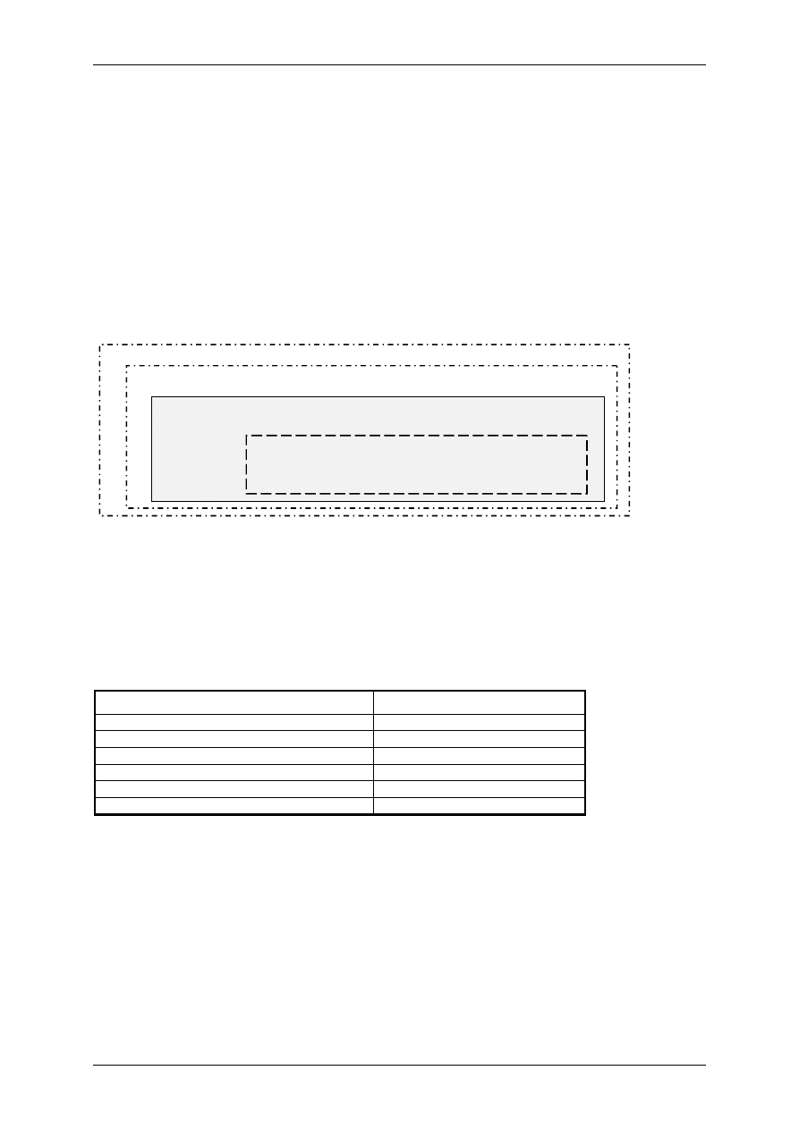
according to EN 1127-1 (2011) and EN 13463-1 (2009). Basically, four definitions of ignition sources
clarified by EN 13463-1 (2009) can be concerned as the guidance of procedures (see Figure 2).
Figure 2. Relationship of possible ignition sources, equipment related ignition sources,
potential ignition sources, and effective ignition sources (EN 13463-1, 2009)
Equipment Related Ignition Sources Identification
EN 1127-1 lists 13 possible ignition sources (see in Table 2). According to the listed possible
ignition sources, the equipment (the targeted emission source) related ignition sources are identified.
During the 13 ignition sources, electrical apparatus, mechanical sparks, and static electricity are the
most frequently identified ignition sources. For some major ignition sources, other standards give more
detailed information. For example, IEC 50404 is especially for the electrostatic source analysis.
Table 2. 13 Possible ignition source list (EN 1127-1, 2011)
- Hot surfaces
- Electromagnetic waves
- Flames, hot gases
- Ionizing radiations
- Mechanical sparks
- High-frequency radiation
- Sparks from electrical equipment
- Ultrasounds
- Static electricity
- Adiabatic compression
- Catholic protection and corrosion protection
- Chemical reactions
- Lightning
Potential Ignition Sources Identification
In terms of EN 13463-1 (2009), Table 3 is used to record the identified potential ignition sources
from the procedure of the equipment related ignition source identification. The column 1 records the
identified potential ignition sources (1a) and basic concerning causes (1b). The column 2 is the
frequency of the occurrence without applying any additional prevention measure or barrier (2a-2d).
Effective Ignition Sources Identification
The final effectiveness of identified potential ignition source should consider with applied barriers.
In Table 4, applied barriers are mentioned in column (3a) with the support of relevant standards (3b)
and received technical documentations (3c). As the result, the frequency of occurrence including
applied barriers (4a-4d) are assessed. In the ATEX-HMI-ISA methodology, the PSA (column e) and
modified results of the effectiveness (column f) are introduced, in order to record the final
effectiveness of the identified potential ignition source with the barrier failure consideration.
Possible Ignition Sources (Identified ignition source listed in EN1127-1)
Equipment Related Ignition Sources
(Ignition source caused by the considered equipment)
Potential Ignition Sources
(Any potential equipment related ignition source that is capable to ignite an explosive
atmosphere)
Effective Ignition Sources
(Any potential ignition source that can ignite an explosive
atmosphere in normal operation, expected malfunction or rare
malfunction)
7
th
European Meeting on Chemical Industry and Environment
EMChIE 2015
Tarragona, 10-12 June 2015
Table 3. Potential Ignition Source Identification (EN 13463-1, 2009)
No.
1
2
Ignition Hazard
Assessment of the frequency of occurrence
without application of an additional measure
a
b
a
b
c
d
e
Potential
Ignition
Sources
Description/
Basic Cause
Duri
ng
n
ormal
op
era
tio
n
Duri
ng
fore
seeable
m
al
fun
c
tio
n
Duri
ng
r
are
m
al
fun
c
tio
n
Not re
levant
Reasons for
Assessment
Table 4. Effective Ignition Source Identification (developed from EN 13463-1, 2009)
3
4
Measures applied to prevent the ignition source becoming
effective
Frequency of occurrence incl. measures applied
a
b
c
a
b
c
d
e
f
Description
of the
measure
applied
Basis (citation of
standards, technical
rules, experimental
results
Technical
documentation
Duri
ng
n
ormal
op
era
tio
n
Duri
ng
fore
s
ee
able
m
al
fun
c
tio
n
Duri
ng
r
are
m
al
fun
c
tio
n
Not re
levant
PSA
Effec
tivenes
s
PSA event tree for the Integrated Safety Assessment (ISA)
To quantify the effectiveness of the identified potential ignition source, the PSA event tree is
introduced, which aims to show the relationship between: 1) the initial probability transferred from the
potential ignition sources identification without applying any barrier (P
IG
), and 2) the potential
probability of barrier failures (PBF). The PBF can be result from the technical barrier failure (Pr
tbf
)
and/or the HOFs barrier failure (HEP).
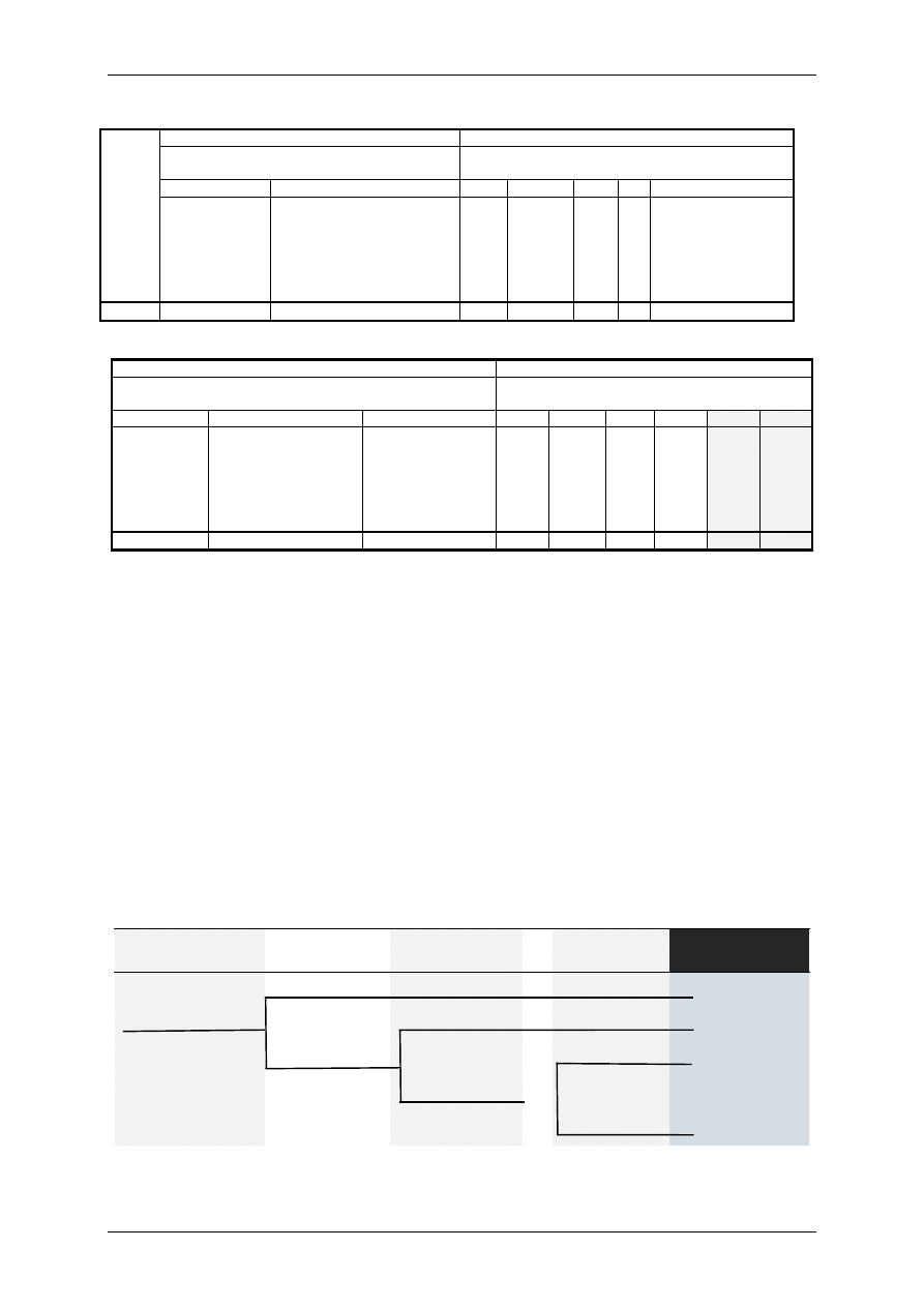
In Figure 3, the PSA event tree is a simplified representation of the accident sequence by using
Boolean logic (Ioannis, 1998). In the Ignition Source Identification of the ATEX-HMI-ISA methodology,
the initial event of the PSA event tree is the initial result from the potential ignition source identification
without applying any barriers (see Table 3). A series of possible paths are constructed by each applied
barriers (see Table 4). Each path is assigned with a probability of occurrence. As the final
effectiveness of the identified potential ignition source is calculated in case of only when all the
prevention measures are failed, the equation is expressed as:
PSA = Pr
IG
× Pr
BF1
× Pr
BF2
× … × Pr
BFN
= Pr
IG
× ∏ (Pr
BFi
), i = 1, 2, … , N Eq. (1)
where, PSA is the probability of the effectiveness of the identified potential ignition source. Pr
IG
is the
initial probability transferred from the potential ignition sources identification without applying any
barrier. Pr
BSi
is the probability of the i
th
barrier succeeding to be active as a prevention measure. Pr
BFi
is the probability of the i
th
barrier failure.
Initial Result without
Prevention Measures
Barrier 1: e.g.
Technical
Prevention
Barrier 2: e.g.
Technical
Prevention
…
…
Barrier N: e.g.
HOFs Prevention
Consequence
Figure 3. PSA Event Tree
The initial probability
from the potential
ignition sources
identification without
applying any prevention
measure (P
IG
)
Pr (Barrier 1, Succeed)
Pr (Barrier 1, Failure)
Pr (Barrier 2, Succeed)
Pr (Barrier 2,
Failure)
Pr (Barrier N, Succeed)
Pr (Barrier N, Failure)
…
…
Pr
IG
× Pr
BS1
Pr
IG
× Pr
BF1
× Pr
BS2
Pr
IG
× Pr
BF1
× Pr
BF2
× … × Pr
BSN
Pr
IG
× Pr
BF1
× Pr
BF2
× … × Pr
BFN

7
th
European Meeting on Chemical Industry and Environment
EMChIE 2015
Tarragona, 10-12 June 2015
Transferring qualitative results into quantitative numbers
Since the initial result from the potential ignition sources identification (see in Table 3) is a
quantitative value, it cannot be calculated directly in the PSA event tree. Different from Area
Classification (Geng, et al., 2014) that can take advantage of probability indexes from the Italian
Guidelines CEI 31-35 (2012) and CEI 31-56 (2007), the Ignition Source Identification of the ATEX-
HMI-ISA methodology is trying to link the uniform probability ranges from the Area Classification by
taking into account the same frequency of occurrence descriptors (see in Table 5).
Table 5. Linking probability ranges with the frequency of occurrence
Effectiveness
Frequency of Occurrence
Assessment for Ignition
Sources (EN 13463-1, 2009)
Probability of Explosive Atmosphere
Formation in 365 days
(CEI 31-56, 2007; CEI 31-35, 2012)
Area
Classification
Frequently
During normal operation
P>10
-1
Zone 0/20
Occasionally
During foreseeable malfunction
10
-1
≥P>10
-3
Zone 1/21
Rarely
During rare malfunction
10
-3
≥P>10
-5
Zone 2/22
Neglectable
Not relevant
10
-5
>P
Zone NE
STEP 3 AND STEP 4: CONSEQUENCE ANALYSIS AND ATEX RISK EVALUATION
Consequence Analysis in the standard ATEX risk assessment is relied on the area classification.
Given to the guide of application for the ATEX risk assessment from Cavaliere and Scardamaglia
(2005) and Cavaliere (2011), the following formulas and indexes (see in Table 6) support the
calculation of the semi-quantitative D value that is used for the ATEX Risk Evaluation (step 4). If the
zone prediction changes in the step 1 (Area Classification), the D value is also changed as D
HOF
.
D’
HOF
= D
HOF
+ PL + KST + VZ + SS + CN (for dust)
D’
HOF
= D
HOF
+ PL + KG + VZ + CN (for gas)
Table 6. Indexes for the D value estimation (Cavaliere, 2011)
Factors
Unit of
Factors
Indexes
0
0.2
0.4
0.6
Zone NE
Zone 2 or Zone 22
Zone 1 or Zone 21
Zone 0 or Zone
20
Personnel
presence (PL)
--
Absent of Work
Occasional Work
Intermittent
Work
Continuous
Work
Dust explosion
index (Kst)
(bar x m/s)
< 10
10 to 50
51 to 100
> 100
Gas explosion
index (KG)
(bar x m/s)
< 10
10 to 50
51 to 100
> 100
Cloud volume (VZ)
(dm3)
0
≤ 1
1 ≤ 10
> 10
Layer thickness
(SS)
(mm)
Absent
≤ 5
5 ≤ 50
> 50
Confined Dust
Cloud (CN)
Not Expected
Not Confined
Partly Confined
Completed
Confined
According to the obtained PSA from the step 1 (Area Classification) and step 2 (Ignition Source
Identification), the semi-quantitative values of P
HOF
and C
HOF
are determined (see Table 7). With the D
value calculated from the formula mentioned in the step 3 (Consequence Analysis), the ATEX-HMI
risk (R
HOF
) is the multiplication of P
HOF
, C
HOF
, and D’
HOF
(R
HOF
= P
HOF
*C
HOF
*D’
HOF
). The final risk level
refers to Table 8.
Table 7. The semi-quantitative ranking system for the ATEX risk evaluation
Area
Classification
Zone
Probability of Explosive
Atmosphere Formation in 365
days (CEI 31-56, 2007)
Semi-Quantitative Ranking System
Degree
P or P
HOF
C or C
HOF
D or D
HOF
Zone 0/20
P>10
-1
Frequently
3
3
0.6
Zone 1/21
10
-1
≥P>10
-3
Occasionaly
2
2
0.4
Zone 2/22
10
-3
≥P>10
-5
Rarely
1
1
0.2
Zone NE
10
-5
>P
Neglectable
0
0
0
Note:
- The D value showed in the table is based on the area classification zones and is only the part of the D’ value calculation;
- The D’ value is the sum of D value and other factors showed in Table 5; the maximum value of D’ for gas is 3, and the
maximum value of D’ for dust is 3.6.

7
th
European Meeting on Chemical Industry and Environment
EMChIE 2015
Tarragona, 10-12 June 2015
Table 8: ATEX-HMI risk evaluation criteria
Risk Level
Risk Value
High
R ≥ 18
Medium
9 ≤ R < 18
Low
1 < R <9
Negligible
R ≤ 1
CONCLUSION
This study aims to provide the advanced methodology that is able to analyse the HOFs influences on
ATEX hazards.
Two challenges are addressed in the developed ATEX-HMI-ISA methodology: 1) in
order to identify the HOFs influence under the Human-Machine Interaction (HMI) system, each step of
the standard ATEX risk assessment was analyzed. Finally, the HOFs is identified as a barrier for the
further quantification. 2) PSA event tree was proposed for the Integrated Safety Assessment (ISA)
which enable to integrate the transferred initial quantitative results of each step from the standard
ATEX risk assessment and the potential barrier failures.
Acknowledgements
This research is supported in part by the INNHF project ---- “Innovation through Human Factors in risk analysis
and management”. The project is financed under EU FP7 Marie Curie Actions Initial Training Networks-FP7-
PEOPLE-2011-ITN: Project ID 289837.
References
Cavaliere A., and Scardamaglia P., 2005, Guida all’applicazione delle direttive ATEX, EPC S.R.L., Italy (in Italian).
Cavaliere A., 2011, Manual for the ATEX application---- Area Classification, Risk Assessment and Management of Explosive
Atmospheres, EPC S.R.L., Italy: Rome, pp.331-333 (in Italian).
CEI EN 60079-10-1, 2010, Explosive atmospheres - Classification of areas - Explosive gas atmospheres, Italian
Electrotechnical Committee.
CEI 31-35, 2012, Equipment for use in the presence of combustible gas – Guide for classification of hazardous area, Italian
Electrotechnical Committee (in Italian).
CEI 31-56, 2007, Equipment for use in the presence of combustible dust – Guide for classification of hazardous area, Italian
Electrotechnical Committee (in Italian).
CEI CLC/TR 50404, 2003, Electrostatics - Code of practice for the avoidance of hazards due to static electricity.
Demichela, M., Pirani, R., Leva, M.C., 2014, Human factor analysis embedded in risk assessment of industrial machines:
Effects on the safety integrity level. International Journal of Performability Engineering, 10 (5), 487-496.
EN 13463, 2009, Non-electrical equipment for use in potentially explosive atmospheres.
EN 61241-14, 2004, Electrical apparatus for use in the presence of combustible dust – Part 14: Selection and installation.
Geng J., Mure S., Camuncoli G., & Demichela M., 2014, Integration of HOFs into ATEX risk assessment methodology,
Chemical Engineering Transactions, 36, 583-588. DOI: 10.3303/CET1436098
Geng J., Mure S., Baldissone G., Camuncoli G., & Demichela M., 2015, Human Error Probability Estimation in ATEX-HMI
Area Classification: from THERP to FUZZY CREAM, Chemical Engineering Transactions, 43.
Hollnagel E., 1998, Cognitive Reliability and Error Analysis Method: CREAM, Oxford: Elsevier Ltd.
Ioannis A. P., 1998, Mathematical foundations of event trees. Reliability Engineering and System Safety, 61(3), 169-183.
Piccinini N., Demichela, M., 2012, Five dead and five injured in a dimethyl terephthalate plant accident: Serious errors in the
plant design coupled with incorrect maintenance management. Industrial and Engineering Chemistry Research, 51 (22),
7619-7627.
Swain A.D., Guttmann H.E., 1983, Handbook of Human Reliability Analysis with emphasis on Nuclear Power Plant Applications,
NUREG/CE-1278. Washington, DC: US Nuclear Regulatory Commission.
UNI EN 1127-1, 2011, Explosive atmospheres - explosion prevention and protection - Part 1: Basic concepts and
methodology.
Wyszukiwarka
Podobne podstrony:
PEAR, Gender Differences In Human Machine Anomalies
Dangerous substances and explosive atmospheres
Human Machine Interfaces 2010
Human Development Index
ATEX ocenaryz
Human Terrain System
ce 9070 atex XN5DU4L7GXIYMA4EXWVLQS7ZLRYFGAHSHPZ2SEY
Building A Wind Machine
Rodzaje pracy silników elektrycznych, 04. 01. ELECTRICAL, 07. Elektryka publikacje, 07. Electrical M
konspekt ?humanizacja sztuki
atex pt1 001 00 OVPNARE2QMCO7WCRAAQCSRMYHRGJUW7QY6HYYJQ
Maslow (1943) Theory of Human Motivation
nauki human w med id 315728 Nieznany
Homework Event Based State Machine Alarm Clock
Hollow Earth Expedition Inside the Drilling Machine
Improvised Explosive Devices Booklet of Related Readings
human development14 technical notes
więcej podobnych podstron